

Page 1

User’s manual
product code: 991247
Page 2

1
SC-12/R
CODE 991247
SCANNER
SC-12/R
INTRODUCTION................................................................................................page 2
SAFETY PRECAUTIONS...................................................................................page 3
TECHNICAL FEATURES...................................................................................page 4
ASSEMBLING...................................................................................................page 5
CONNECTION TO THE POWER SUPPLY.........................................................page 6
MOUNTING AND REPLACING THE LAMP......................................................page 7
FOCUS AND MIRROR ADJUSTMENT.............................................................page 8
GOBOS REPLACEMENT...................................................................................page 8
DMX SIGNAL CONNECTION............................................................................page 9
CONFIGURATION AND CONTROLS................................................................page 10
SWITCH “OPTIONS”.........................................................................................page 11
DMX CHANNELS FUNCTIONS........................................................................page 12
TROUBLESHOOTING.......................................................................................page 13
•TABLE 1 - GENERAL PROBLEMS........................................................page 13
•TABLE 2 - PROBLEMS TO THE CONNECTION DATA LINK...............page 14
•MOTORS PC BOARD...........................................................................page 15
MAINTENANCE................................................................................................page 18
APPENDIX “A” - 8 CHANNELS CONFIGURATION..........................................page 18
INDEXINDEX
INDEXINDEX
INDEX
Page 3

2
We thank you for choosing the SC-12/R.
Characterized by an attracting design and an
incredible optic system, the SC-12/R is suitable
for any kind of ambient.
A modern and reliable electric circuit gives
stability and functioning safety for long time.
To make the most of this unit and to make it
work correctly in the years, before connecting
it to its source and using it, we suggest you to
carefully read this manual.
In this way you could be more familiar with
its commands and connections so to easily
use it.
INTRODUCTIONINTRODUCTION
INTRODUCTIONINTRODUCTION
INTRODUCTION
All the sections of this manual have been studied to make as easy and complete as possible the use of the SC-12/R.
To make the manual more clear and easy to consult, we have used the following symbols and conventions:
very important warnings, to be read with the maximum attention;
important parts of the text that give details and/or explanations on the use of
the SC-12/R.
practical advices for an efficient use of the SC-12/R.
!
IMPORTANT
!
The safety of the unit is guaranteed only strictly following the instructions, so it is recommended
to accurately preserve them.
SC-12/R
CODE 991247
Page 4
3
•PROTECTION AGAINST FIRE
1) This unit has been made to work only with the Lamp: HMI 1200W GS (OSRAM).
! ABSOLUTELY NEVER USE OTHER KIND OF LAMPS.
2) Keep a minimum distance of 0,3 mt. from walls or any inflammable surface.
3) Keep a minimum distance of 1 mt. from lighted objects.
4) Replace the fuses with others of the same kind and value (5x20 250V 10A).
5) Do not install the projector close to heat sources. Do not lay the connection cables on the projector when it is hot.
•PROTECTION AGAINST ELECTRIC SHOCKS
1) This projector must be earthed.
2) Class I equipment. The protection conductor must be part of the power supply cable.
3) For the connection to the main power supply proceed as in fig. 2/a, page 6.
4) Disconnect the power supply before the Lamp replacement or before opening the unit.
5) Do not install the projector outdoors, exposed to rain or moisture.
•PROTECTION AGAINST MECHANICAL HAZARDS
1) When installing the projector use a safety chain.
2) To avoid explosion risks, open the projector only after 5 minutes after the lamp is off.
3) The temperature of the projector can reach high levels. Wait for almost 5 minutes before operating on it.
4) Replace the Lamp if it is damaged or deformed by the heat.
•PROTECTION AGAINST UV RADIATIONS HAZARDS
1) Do not start on the projector without the protecting screen or if the lenses and the ultra-violet filters are
damaged.
2) The protecting screens, the lenses and the ultra-violet filters must be replaced if visibly damaged and if their
efficiency has been reduced, for example by slits or deep cuts.
3) Do not directly look at the Lamp when it is on.
•WARNINGS
1) Do not dismantle and modify the unit.
2) To avoid any inflammable liquids, water or metal objects entering the unit.
SAFETY PRECASAFETY PRECA
SAFETY PRECASAFETY PRECA
SAFETY PRECA
UTIONSUTIONS
UTIONSUTIONS
UTIONS
READ ALL CAUTIONS AND WARNINGS PRIOR TO OPERATE THIS EQUIPMENT.
INSTRUCTIONS TO PREVENT INJURIES OR DAMAGES DUE TO FIRE, ELECTRIC SHOCKS, MECHANICAL
HAZARDS AND UV RADIATIONS HAZARDS.
IMPORTANT
!
SC-12/R
CODE 991247
Page 5

4
SAFETY PRECASAFETY PRECA
SAFETY PRECASAFETY PRECA
SAFETY PRECA
UTIONSUTIONS
UTIONSUTIONS
UTIONS
Make sure that the unit has not been damaged during the transportation.
In case it has happened or in case the unit does not work correctly, immediately contact the Retailer.
If the unit has been directly sent to you , immediately contact the Freight Company.
Only the final receiver (the person or the Company that receive the unit) is in the position to
complain for the above inconveniences.
YOUR REFERENCE
Cite the model and the serial number anytime you contact your retailer to ask for information or assistance.
STANDARD PACKAGE
The standard package of the SC-12/R contains:
1) Projector ON REQUEST:
2) Mains connector * Lamp (code 060268)
3) DMX XLR5 (pc. 2) signal connectors * Flight Case without wheels (code 194979)
4) User’s manual * Black clamp Ø50 (code 194019)
5) Guarantee
IMPORTANT
!
TECHNICAL FEATECHNICAL FEA
TECHNICAL FEATECHNICAL FEA
TECHNICAL FEA
TURESTURES
TURESTURES
TURES
SC-12/R
CODE 991247
PMALPMAL
PMAL
PMALPMAL
)MARSO(SGW0021IMHpmalegrahcsiD
K°006.5:erutarepmetruoloC
sruoh057:efilpmalegarevA
TNEMEVOMTNEMEVOM
TNEMEVOM
TNEMEVOMTNEMEVOM
.TLIT°04,NAP°081:.cd2+srotomreppetS6
dnalatnoziroheht,srotomreppetsehtfospets-orcimfometsysdetacitsihposaotsknahT
wolsdnatsafhtobnietaruccadnaraenilylemertxeerarorrimehtfostnemevomlacitrev
.stnemevom
LACITREVLACITREV
LACITREV
LACITREVLACITREV
TNEMEVOM
°05-/°05+
.noitatneirolaunaM
SRUOLOCSRUOLOC
SRUOLOC
SRUOLOCSRUOLOC
.)7egap,a/3.gif(ETIHW+)elbaegnahcretnilla(SRUOLOC9
.)tceffewobniar(leehwruolocehtfodeepsnoitatorehtetalugerotelbissopsitI
SOBOGGNITATORSOBOGGNITATOR
SOBOGGNITATOR
SOBOGGNITATORSOBOGGNITATOR
.)7egap,a/3.gif(ETIHW+)elbaegnahcretnilla(SOBOGGNITATOR6
.)tceffewobniar(leehwobogehtfodeepsnoitatorehtetalugerotelbissopsitI
SOBOGDEXIFSOBOGDEXIF
SOBOGDEXIF
SOBOGDEXIFSOBOGDEXIF
.)7egap,a/3.gif(ETIHW+)elbaegnahcretnilla(SOBOGDEXIF9
.)tceffewobniar(leehwobogehtfodeepsnoitatorehtetalugerotelbissopsitI
TUOKCALB/OBORTSTUOKCALB/OBORTS
TUOKCALB/OBORTS
TUOKCALB/OBORTSTUOKCALB/OBORTS
.ycneuqerfelbatsujdanahtiwtceffeOBORTS;tceffeTUOKCALB
.).ces/hsalf21.xam,.ces/hsalf1.nim(
MSIRPGNITATORMSIRPGNITATOR
MSIRPGNITATOR
MSIRPGNITATORMSIRPGNITATOR
.deepsnoitatorelbatsujdA.msirPsecaf-eerhtgnitatoR
MAEBTHGILMAEBTHGIL
MAEBTHGIL
MAEBTHGILMAEBTHGIL
EDUTILPMA
.ecnatsidfo.tm6tarotcejorpehthtiw,)°5,31(.tm3,1.maiD
REWOPTUPNIREWOPTUPNI
REWOPTUPNI
REWOPTUPNIREWOPTUPNI
.zH05;caV032:egatlovgnitarepolanimoN•
.W0031:ylppusrewopdetaR•
.)caV032(A01:tnerruclanimoN•
GNIKROWGNIKROW
GNIKROW
GNIKROWGNIKROW
NOITISOP
.noitisopynA
SNOISNEMIDSNOISNEMID
SNOISNEMID
SNOISNEMIDSNOISNEMID
)HxDxW(
.)5egap,1.giF(593x028x084.mm
THGIEWTHGIEW
THGIEW
THGIEWTHGIEW
33.gK
YDOBYDOB
YDOB
YDOBYDOB
.muinimuladnaleetS
Page 6

3
9
5
m
m
.
fig. 1
5
TECHNICAL FEATECHNICAL FEA
TECHNICAL FEATECHNICAL FEA
TECHNICAL FEA
TURESTURES
TURESTURES
TURES
BRACKET
MANUAL ORIENTATION
KNOBS
ASSEMBLINGASSEMBLING
ASSEMBLINGASSEMBLING
ASSEMBLING
! Before installing the SC-12/R, make sure that the carrying structure is safe and able to support the weight of
the unit.
The SC-12/R is equipped with a bracket with three holes (diam. 10 mm.) to fix clamps and/or screw bolts (fig. 1).
To orientate the unit, follow these instructions:
1) Unscrew the knobs placed at the both sides of the unit (fig. 1);
2) Orientate the unit in the preferred position;
3) Screw the above said knobs.
! Once finished make sure that the unit is correctly fixed and stable.
! Always make sure that you are using a safety chain.
! Do not install the unit outdoor directly exposed to rain or moisture.
! To avoid installing the projector close to heat sources.
! The unit must be at a minimum distance of 30 cm. from the walls or from any inflammable material and 1 mt.
from lighted objects.
! The unit must be placed where it could be easily aerated. To avoid obstructing the in/out air gratings.
SC-12/R
CODE 991247
Page 7

ITALY
SC-12/R HMI 1200
230
1300
55/02
Hz
Amp.
Lamps
Max. Temp.
50
10
S.R.L.
SPEC.
50°C
HMI 1200
fig. 2
6
BEFORE USING THE PROJECTOR
! Carefully read the precautions on page 3 before installing the projector.
In particular read the following points:
1) Disconnect the power supply before replacing the lamp or doing any maintenance job.
2) Do not open the projector if are not passed at least 5 minutes after it went off.
3) Always wear protective gloves and goggles to replace the lamp or to work inside the projector.
4) The protecting screens, the lenses and the ultra-violet filters must be replaced if visibly damaged.
Slits or deep cuts remarkably reduce their efficiency.
5) To avoid any bad performance of the projector or that the lamp breakage could damage its optic,
replace the lamp as soon as it reaches its average life time (750 hrs).
6) Periodically clean the in/out air grates.
7) In case the projector must be held on a structure (truss), make sure that it is well and safely fixed,
even using a safety chain from the projector to the structure.
8) Do not install the projector outdoors, directly exposed to rain and moisture.
9) Before connecting the projector to the main power supply, make sure that the working voltage and
frequency correspond to the values indicated on the label (fig. 2).
The SC-12/R is supplied to work at a working voltage of 230V 50Hz (60Hz on request); 10A.
For being supplied with a voltage of 100-120V it is absolutely necessary an auto-transformer with
the following characteristics:
• Output voltage 230V.
• Output current 11A.
10) The connection of the projector to the mains is described in fig. 2/a:
10 a) Do not install the projector close to heat sources. Do not lay the connection cables on the
projector when it is hot.
10 b) The unit must be placed where it could be easily aerated. To avoid obstructing the in/out air
gratings.
10 c) The projector must be distanced almost 0,3 mt. from walls or any inflammable surface
and almost 1mt. from lighted objects.
The unit must be connected to the earth. The inobservance of these
instructions automatically makes the guarantee expiring.
CONNECTION TCONNECTION T
CONNECTION TCONNECTION T
CONNECTION T
O THE POWER SUPPLO THE POWER SUPPL
O THE POWER SUPPLO THE POWER SUPPL
O THE POWER SUPPL
YY
YY
Y
IMPORTANT
!
POWER SUPPLY INPUT
SC-12/R
CODE 991247
fig. 2/a
L = PHASE (Brown)
N = NEUTRAL (Blue)
= EARTH (Green - Yellow)
THREE POLES FEMALE CONNECTOR
FOR THE CONNECTION TO THE MAINS
LN
Page 8
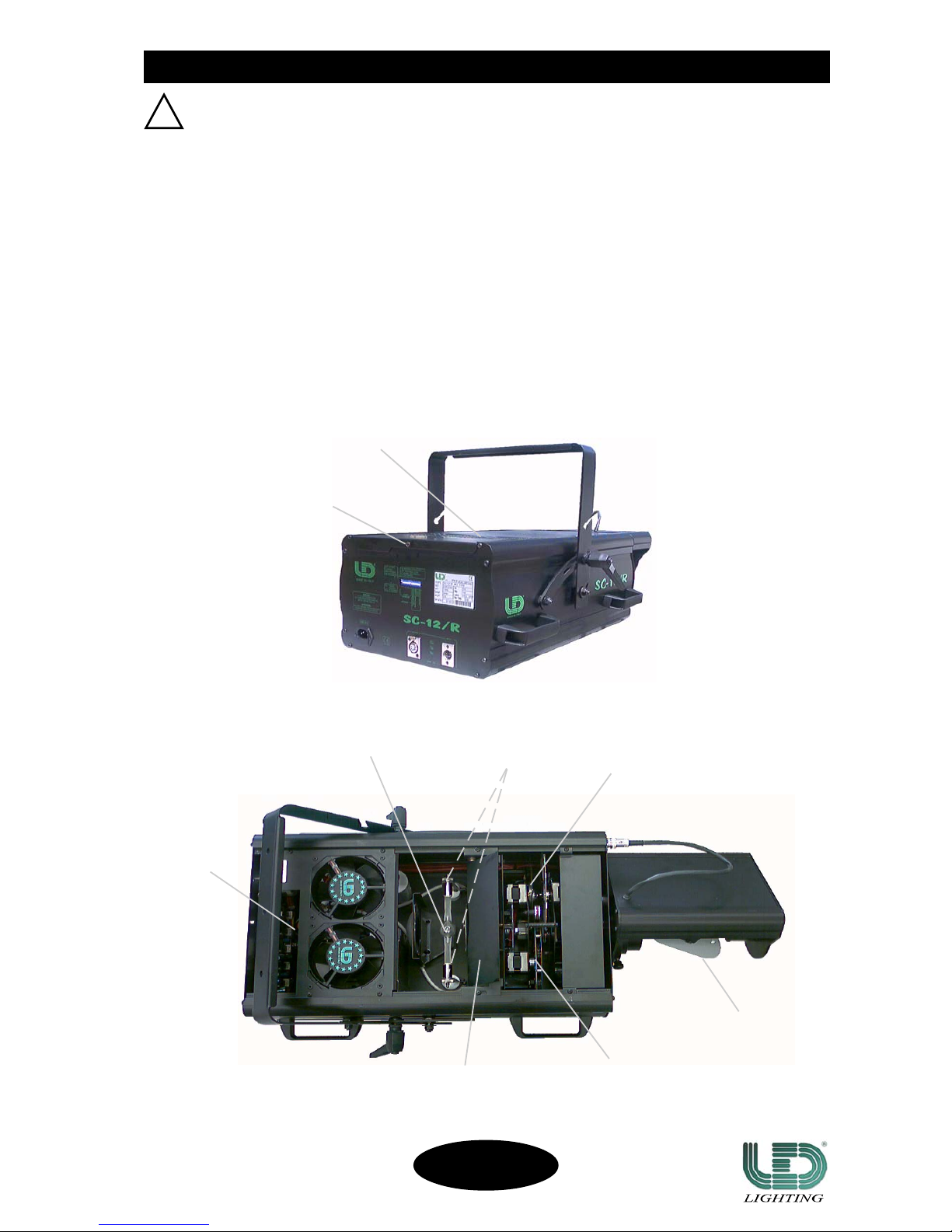
fig. 3/a
fig. 3
7
LOCKING BOLT
TOP COVER
LAMP
PROTECTION COVER
OF THE LAMP
LATERAL BUSHES
GOBOS
COLOURS
THERMIC
PROTECTOR
MIRROR
1) Disconnect the projector before replacing the lamp. Wear protective gloves and goggles.
2) Unscrew the locking bolt of the rear panel of the projector (fig. 3).
3) Take out the top cover and disassemble the lamp, pushing it towards its spring clip and rotating it up (fig. 3 and 3/a).
4) Undo the two lateral bushes of the lamp and take it out (fig. 3/a).
Before mounting the new lamp, make sure that into the lamp holder there is not anything that may cause
interruptions to the thermic and electrical conduction.
5) Undo the two lateral bushes of the new lamp and insert it in the lamp holder positioning up the bulb protuberance,
fasten the lamp bushes.
! Avoid touching the new lamp with the nude hands; in case it accidentally happens, clean the bulb with the
proper tissue given with the replacement lamp.
6) Make sure the spring clip is back in its place, assemble the top cover and the locking bolt.
MOUNTING AND REPLAMOUNTING AND REPLA
MOUNTING AND REPLAMOUNTING AND REPLA
MOUNTING AND REPLA
CING THE LAMPCING THE LAMP
CING THE LAMPCING THE LAMP
CING THE LAMP
In case of replacement of the Lamp or maintenance, never open the unit
unless are passed at least 5 minutes after it went off.
IMPORTANT
!
SC-12/R
CODE 991247
Page 9
8
FOCUS AND MIRROR ADJUSTMENTFOCUS AND MIRROR ADJUSTMENT
FOCUS AND MIRROR ADJUSTMENTFOCUS AND MIRROR ADJUSTMENT
FOCUS AND MIRROR ADJUSTMENT
fig. 4
GOBOS REPLAGOBOS REPLA
GOBOS REPLAGOBOS REPLA
GOBOS REPLA
CEMENTCEMENT
CEMENTCEMENT
CEMENT
To do this operation, it is suggested to use two GOBOS with patterns superinposition (i.e. GOBO B “ROTATING
GOBO wheel” + GOBO B “FIXED GOBO wheel”).
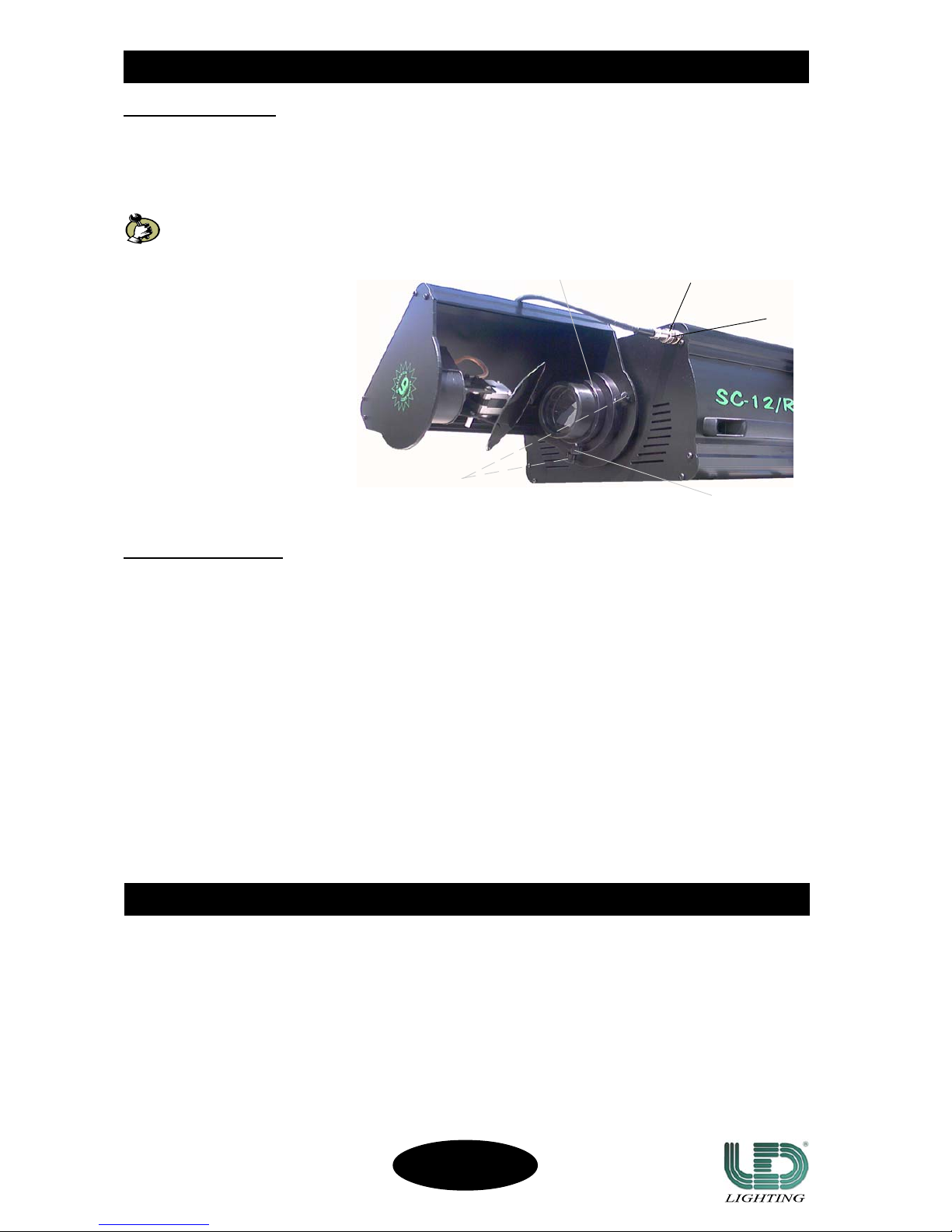
FOCUS ADJUSTMENT
To focus do as follows:
• loosen the knob placed on the objective (fig. 4);
• move the objective forwards/backwards to reach the best focus;
• fasten the knob.
MIRROR ADJUSTMENT
It is possible to orientate the mirror housing, turning it of 180° right/left. To do the above mentioned operation it is
necessary to:
• loosen the two knobs placed on both sides of the objective, using a cross screw driver (fig. 4);
• orientate the mirror housing until the preferred position is reached;
• lock the two knobs.
It is also possible to remove the mirror housing. To do the above mentioned operation it is necessary to:
• unscrew the focus regulation knob;
• loosen the two mirror regulation knobs;
• disconnect the connector, unscrewing the appropriate bush (fig. 4);
! ATTENTION: disconnect/connect the connector only when the projector is Off.
• take off the mirror housing;
• screw the focus regulation knob.
To assemble again the mirror housing, do the above mentioned instructions in the opposite direction.
OBJECTIVE
MIRROR
REGULATION KNOB
FOCUS REGULATION
KNOB
BUSH
CONNECTOR
SC-12/R
CODE 991247
To replace the GOBOS is extremely simple:
1) Disconnect the projector from the power supply;
!In case it has been recently used, make sure that has cooled down.
2) Unscrew the locking bolt of the rear panel of the projector and take out the top cover (fig. 3, page 7);
3) Keep stopped the rotor and softly take out the spring using a pointed object;
4) Replace the GOBO and softly take back the spring.
!Never push on the GOBO to take out the spring, to avoid damaging the same GOBO and/or the rotor.
Page 10
DMX CONTROLLER
LINE TERMINAL
PROJECTOR
LINE TERMINAL
DMX CONTROLLER
DMX CONTROLLER
LINE TERMINAL
LINE TERMINAL
LINE TERMINAL
9
DMX LINE TERMINAL
Do not connect or wrongly connect the DMX line terminal is probably the most common cause of a defective
functioning of a DMX line.
The DMX line terminal is a resistance placed between the two data pin 2 and 3 at the end of the line.
The terminal resistance should ideally have the same value of the impedance of the DMX connecting cable.
It is recommended, for all DMX system, to insert the line terminal into the DMX output connector of the last
connected projector .
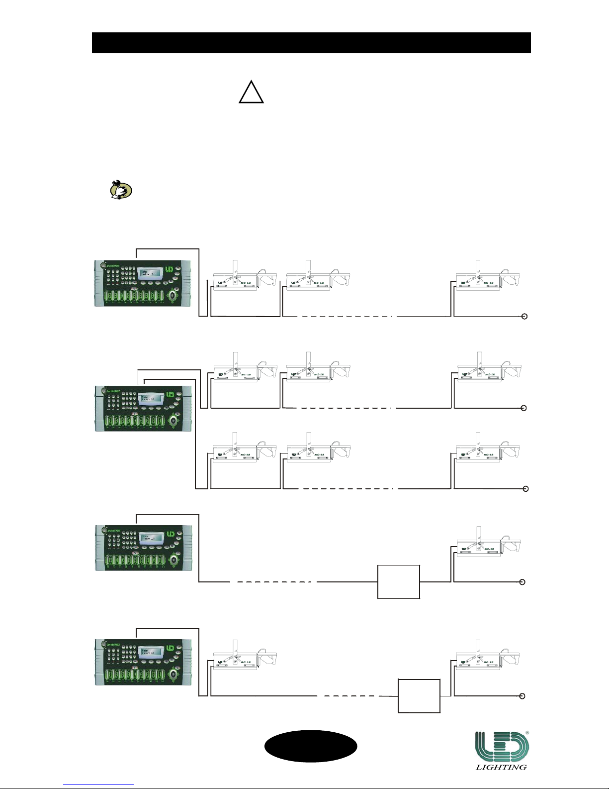
EXAMPLES OF CONNECTIONS: DMX CONTROLLER - PROJECTOR
DMX CONTROLLER
DMX SIGNAL CONNECTIONDMX SIGNAL CONNECTION
DMX SIGNAL CONNECTIONDMX SIGNAL CONNECTION
DMX SIGNAL CONNECTION
It is suggested to use a DMX line terminal with a resistance value of 100/120 Ohm.
We supply, on request, a DMX line terminal with a resistance value of 120 Ohm.
IMPORTANT
!
PROJECTOR
PROJECTOR PROJECTOR
PROJECTOR
PROJECTOR
LAST PROJECTOR
LINE < 100mt. (with microphonic or audio cable)
LINE < 100mt. (with microphonic or audio cable)
PROJECTOR
LAST PROJECTOR
LAST PROJECTOR
LAST PROJECTOR
LAST PROJECTOR
SIGNAL
AMPLIFIER
DMX 1 output line
DMX 2 output line
EXAMPLE 1
Controller-projector connection with
only one DMX 512 OUTPUT LINE
SIGNAL
AMPLIFIER
EXAMPLE 2
Controller-projector connection with
two or more DMX 512 OUTPUT LINE
EXAMPLE 3
Controller-projector connection with only one
DMX 512 OUTPUT LINE long more than 150mt.
EXAMPLE 4
Controller-projector connection with only one
DMX 512 OUTPUT LINE long more than 150mt.
LINE > 150mt. (with microphonic or data transmission cable)
LINE > 150mt. (with microphonic or data transmission cable)
LINE < 100mt. (with microphonic or audio cable)
SC-12/R
CODE 991247
Page 11
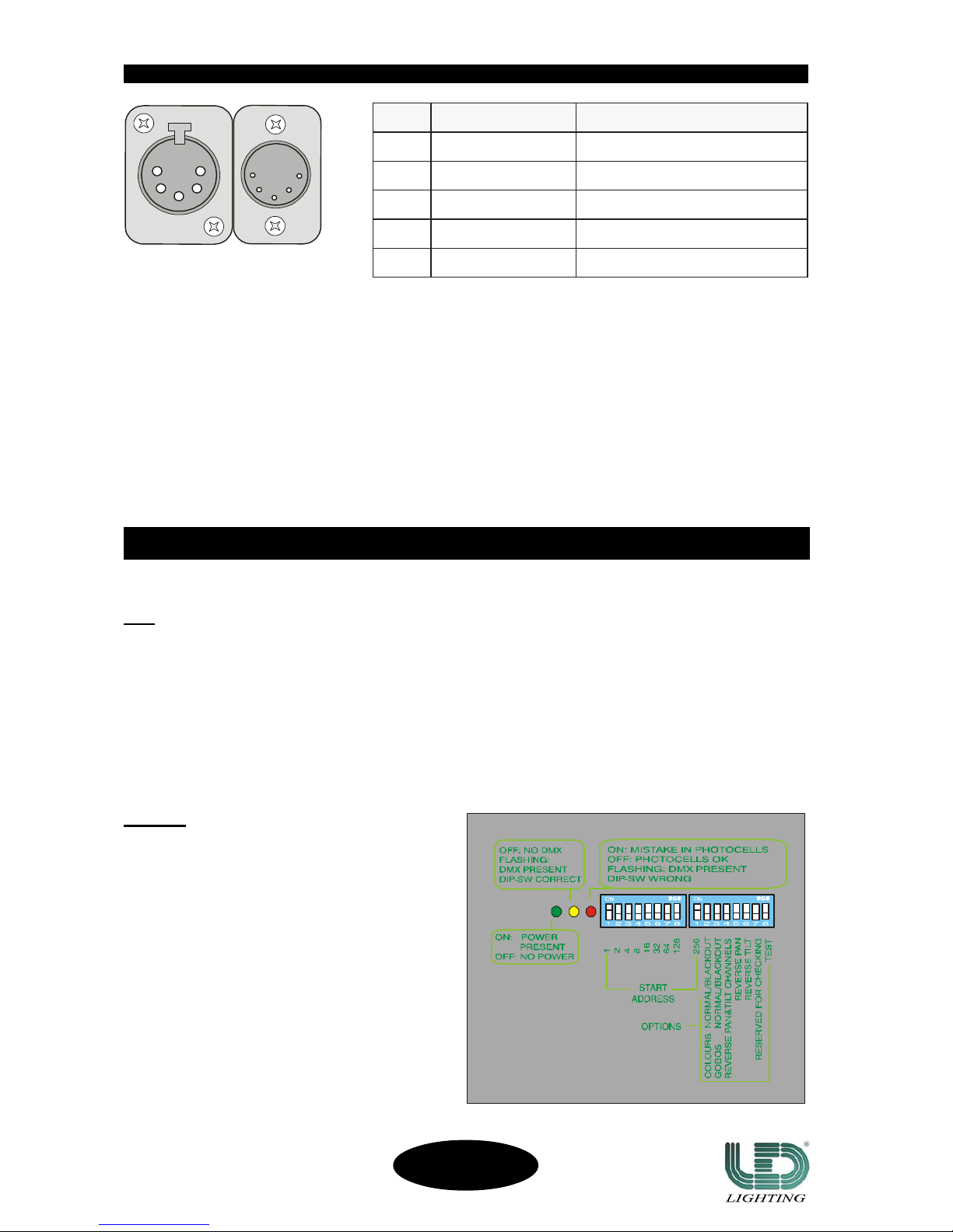
fig. 5
fig. 5/a
On the rear panel of the SC-12/R (fig. 6) there are some led and some switches to correctly configure the projector.
LEDLED
LEDLED
LED
• Led “POWER” (green) on: the main pc board receives the right power supply;
off: the main pc board is not supplied.
• Led “DMX” (yellow) flashing: the DMX input signal is on;
off: the dmx input signal is out.
• Led “CONTROL” (red) on: the ROTATING GOBO and the COLOUR wheels have not been
properly settled;
flashing: the DMX address is incorrect;
off: the settling has been correctly executed.
fig. 6
NIPNIP
NIP
NIPNIP ERIWERIW
ERIW
ERIWERIW LANGISLANGIS
LANGIS
LANGISLANGIS
1DLEIHSVO/NRUTER/DNUORG
2ROTCUDNOCRENNI)DETREVNI,-(TNEMELPMOCATAD
3ROTCUDNOCRENNI)DETREVNINON,+(EURTATAD
4.C.N
5.C.N
10
SWITSWIT
SWITSWIT
SWIT
CHCH
CHCH
CH
• START ADDRESS to fix the DMX addresses.
• OPTIONS to activate/not activate
optional functions.
DMX SIGNAL CONNECTIONDMX SIGNAL CONNECTION
DMX SIGNAL CONNECTIONDMX SIGNAL CONNECTION
DMX SIGNAL CONNECTION
DMX SIGNAL CONNECTION
The DMX signal connection to the SC-12/R must be done through the input signal connectors XLR 5 pins, placed on
the rear panel of the projector (fig. 5).
The nomenclature of the pins of the DMX input connectors is listed in the table reported in fig. 5/a.
To avoid any problem in the transmission of the signal it is recommended to use a cable for very fast data
transmissions.
A normal audio cable is suitable only for lines long not more than 100mt.
The best performances and the maximum stability are obtained using a shielded microphonic cable which section
must be of at least 2x0,25mm, or, a data transmission cable.
In case of lines long more than 150/200mt. it is recommended to use a DMX Repeater Amplifier.
CONFIGURACONFIGURA
CONFIGURACONFIGURA
CONFIGURA
TION AND CONTROLSTION AND CONTROLS
TION AND CONTROLSTION AND CONTROLS
TION AND CONTROLS
SC-12/R
CODE 991247
Page 12
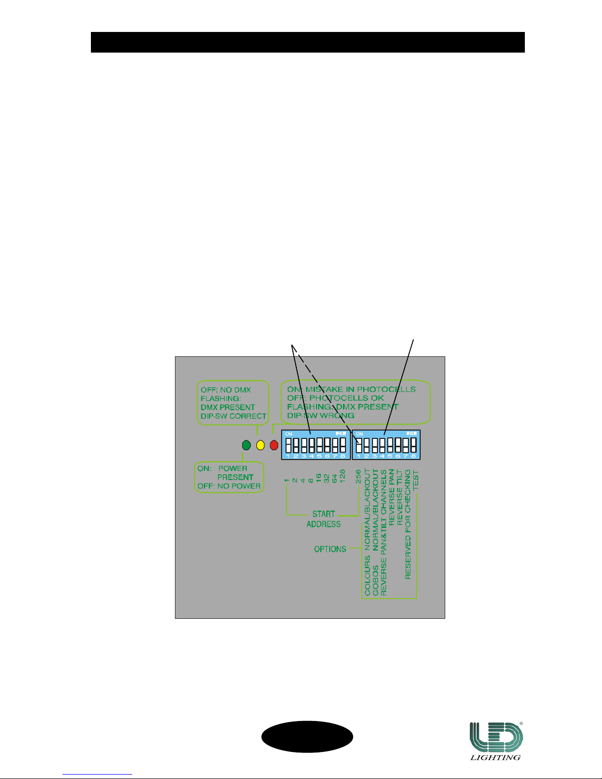
On the rear panel of the projector there are some switches - switch “OPTIONS” (fig. 7) - to be used to activate or not
activate the following options:
• COLOURS NORMAL/BLACKOUT ON: to change colours (COLOUR wheel) obscuring the light beam;
(DIP-SW “2”) OFF: to change colours (COLOUR wheel) not obscuring the light beam.
• GOBOS NORMAL/BLACKOUT ON: to change gobos (ROTATING GOBO wheel) obscuring the light
(DIP-SW “3”) beam;
OFF: to change gobos (ROTATING GOBO wheel) not obscuring the
light beam.
• REVERSE PAN&TILT CHANNELS ON: to reverse the PAN/TILT channels,
(DIP-SW “4”) OFF: normal.
• REVERSE PAN ON: to reverse the PAN movement;
(DIP-SW “5”) OFF: normal.
• REVERSE TILT ON: to reverse the TILT movement;
(DIP-SW “6”) OFF: normal.
• RESERVED FOR CHECKING ON: to execute the projector setting;
(DIP-SW “7”) OFF: normal.
• TEST ON: to execute the self-setting;
(DIP-SW “8”) OFF: normal.
11
SWITCH “OPTIONS”SWITCH “OPTIONS”
SWITCH “OPTIONS”SWITCH “OPTIONS”
SWITCH “OPTIONS”
fig. 7
SWITCH “OPTIONS”
SWITCH “START ADDRESS”
SC-12/R
CODE 991247
Page 13
°NLENNAHC°NLENNAHC
°NLENNAHC
°NLENNAHC°NLENNAHC NOITCNUFROTCEJORPNOITCNUFROTCEJORP
NOITCNUFROTCEJORP
NOITCNUFROTCEJORPNOITCNUFROTCEJORP
1MSIRP
2WOBNIAR+SRUOLOC
3WOBNIAR+SOBOGGNITATOR
4DEEPSEBORTS/RETTUHS
5ESRAOCNAP
6ESRAOCTLIT
7SOBOG.TOR
8WOBNIAR+SOBOGDEXIF
ROTCEJORPROTCEJORP
ROTCEJORP
ROTCEJORPROTCEJORP
REBMUN
SLENNAHCSLENNAHC
SLENNAHC
SLENNAHCSLENNAHC
"SSERDDATRATS"HCTIWS"SSERDDATRATS"HCTIWS
"SSERDDATRATS"HCTIWS
"SSERDDATRATS"HCTIWS"SSERDDATRATS"HCTIWS
WS-PIDWS-PID
WS-PID
WS-PIDWS-PID
"1"
WS-PIDWS-PID
WS-PID
WS-PIDWS-PID
"2"
WS-PIDWS-PID
WS-PID
WS-PIDWS-PID
"3"
WS-PIDWS-PID
WS-PID
WS-PIDWS-PID
"4"
WS-PIDWS-PID
WS-PID
WS-PIDWS-PID
"5"
WS-PIDWS-PID
WS-PID
WS-PIDWS-PID
"6"
WS-PIDWS-PID
WS-PID
WS-PIDWS-PID
"7"
WS-PIDWS-PID
WS-PID
WS-PIDWS-PID
"8"
WS-PIDWS-PID
WS-PID
WS-PIDWS-PID
)"1"(
11111 22222 44444 88888 6161616161 2323232323 4646464646 821821
821
821821 652652
652
652652
1.NROTCEJORP
8-1
NONONONONO FFOFFOFFOFFOFFOFFOFFOFFO
2.NROTCEJORP
61-9
NONONONONO FFOFFO NONONONONO FFOFFOFFOFFOFFO
3.NROTCEJORP
42-71
NONONONONO FFOFFOFFO NONONONONO FFOFFOFFOFFO
4.NROTCEJORP
23-52
NONONONONO FFOFFO NONONONONONONONONONO FFOFFOFFOFFO
12
DMX CHANNELS FUNCTIONSDMX CHANNELS FUNCTIONS
DMX CHANNELS FUNCTIONSDMX CHANNELS FUNCTIONS
DMX CHANNELS FUNCTIONS
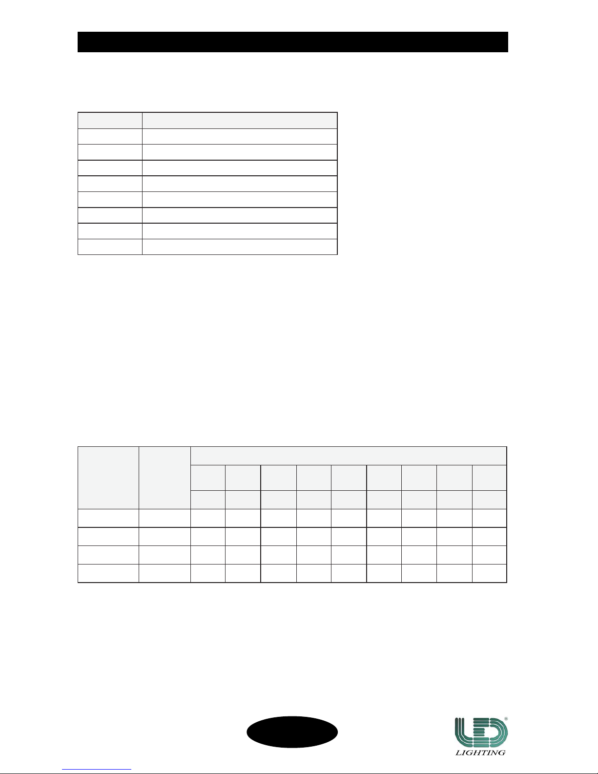
The SC-12/R needs of eight channels to control its functions.
The connection between the channels and the functions of the projector is reported in the below table:
The full list of the DMX values is in the APPENDIX “A”, page 18.
ADDRESS SELECTION
To fix the DMX addresses use the switches “START ADDRESS” (fig. 7, page 11), placed on the rear panel of the
projector.
The flashing of the “DMX” led on the rear panel indicates that the data transmission between the DMX controller
and the projector is working.
In the following table are reported the correct channels for using four projectors SC-12/R (8 channels) in DMX 512.
SC-12/R
CODE 991247
Page 14
13
SMELBORPSMELBORP
SMELBORP
SMELBORPSMELBORP
ELBABORPELBABORP
ELBABORP
ELBABORPELBABORP
SNOSAER
SLORTNOCSLORTNOC
SLORTNOC
SLORTNOCSLORTNOC
DETSEGGUSDETSEGGUS
DETSEGGUS
DETSEGGUSDETSEGGUS
SNOITULOS
seodrotcejorpehTseodrotcejorpehT
seodrotcejorpehT
seodrotcejorpehTseodrotcejorpehT
.tratston
siylppusrewopehT
.gnissim
rewopehterusaeM
ehtnonoisnetylppus
.rotcennoclapicnirp
rotcejorpehtylppuS
.rewopthgirehthtiw
rewopevitcefeD
ro/dnaselbacylppus
.srotcennoc
dnaselbackcehC
.sutatssrotcennoc
selbacecalpeR
.srotcennocro/dna
siesuflarenegehT
.detpurretni
.sutatsesufehtkcehCfi(esufehtecalpeR
)evitcefed
skrowrotcejorpehTskrowrotcejorpehT
skrowrotcejorpehT
skrowrotcejorpehTskrowrotcejorpehT
ehttubyltcerroc
nruttonseodpmal
cimrehteht(no
.gif,nosirotcetorp
.)7egap,a/3
tonsinafehT
.gnikrow
.sutatsnafehtkcehCrotcejorpehtroftiaW
ehtecalpeR.gnilooc
tuP.evitcefedsifi,nuf
rotcetorpcimrehteht
.ffo
riadetcurtsbO
.sgnitarg
-rotcejorpehtroftiaW
riaehtnaelC.gnilooc
ehttupdnasgnitarg
.fforotcetorpcimreht
skrowrotcejorpehTskrowrotcejorpehT
skrowrotcejorpehT
skrowrotcejorpehTskrowrotcejorpehT
ehttubyltcerroc
nruttonseodpmal
yltnettimretnirono
.ffosnrut
.pmalevitcefeDpmalehtkcehC
.sutats
.pmalehtecalpeR
ottohootsipmalehT
.nonrut
-pmalehtroftiaW
.gnilooc
erutarepmettneibmA
.C°54revo
-tneibmaehtnwodtuP
ehtoterutarepmet
ehtrofenolamron
krowotrotcejorp
.)C°04xam(yltcerroc
rewopwolooT
.deilppus
rewopehterusaeM
.deilppus
rewopehtkcehC
.ecruos
.retingievitcefeDretingiehtkcehC
.sutats
.retingiehtecalpeR
tsallabgnorW
.snoitcennoc
tsallabehtkcehC
.snoitcennoc
tsallabehttcennoC
.yltcerroc
snoitcnufehtfoenOsnoitcnufehtfoenO
snoitcnufehtfoenO
snoitcnufehtfoenOsnoitcnufehtfoenO
sirotcejorpehtfo
.e.i(evitcefed
GNITATOR
.)SOBOG
reppetsdegamaD
.rotom
stsetehtetucexE
.51egaptadebircsed
reppetsehtecalpeR
.rotom
rotomdegamaD
.)1773LBP(revird
rotomehtecalpeR
.)1773LBP(revird
GNITATORgnorW
.noitatorleehwOBOG
rewopehttcennocsiD
yllaunamdnaylppus
ehttahtkcehc
OBOGGNITATOR
sinoitatorleehw
.ralugerdnagniwolf
-
TROUBLESHOOTROUBLESHOO
TROUBLESHOOTROUBLESHOO
TROUBLESHOO
TINGTING
TINGTING
TING
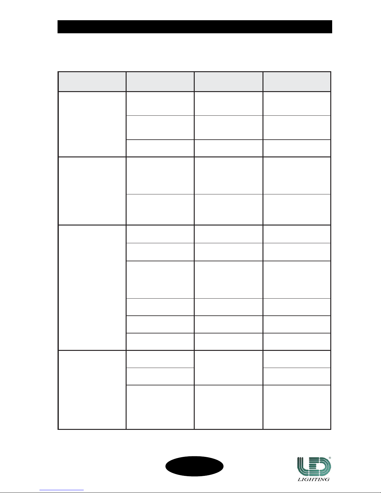
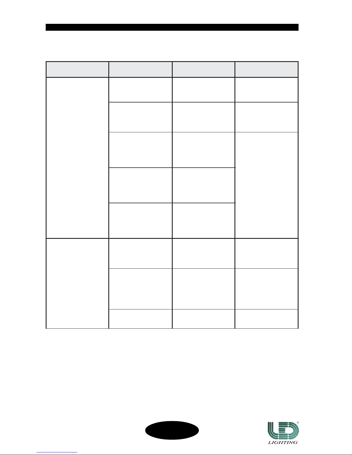
TABLE 1 - GENERAL PROBLEMS
SC-12/R
CODE 991247
Page 15
14
TABLE 2 - PROBLEMS TO THE CONNECTION DATA LINK
SMELBORPSMELBORP
SMELBORP
SMELBORPSMELBORP
ELBABORPELBABORP
ELBABORP
ELBABORPELBABORP
SNOSAER
SLORTNOCSLORTNOC
SLORTNOC
SLORTNOCSLORTNOC
DETSEGGUSDETSEGGUS
DETSEGGUS
DETSEGGUSDETSEGGUS
SNOITULOS
R/21-CSehtfoenoNR/21-CSehtfoenoN
R/21-CSehtfoenoN
R/21-CSehtfoenoNR/21-CSehtfoenoN
ehtotdnopser
.tupnirellortnoc
.dexifsidelXMD
hctiws(nognitset-fleS
WS-PID-"SNOITPO"
.)no"8"
ehterusekaM
ffosignitset-fles
-"SNOITPO"hctiws(
.)ffo"8"WS-PID
gnitset-flesehtffotuP
-"SNOITPO"hctiws(
.)ffo"8"WS-PID
rellortnocXMD
ehtmorfdetcennocsid
.srotcejorp
ehtfikcehC
ehtfonoitcennoc
ehtotrellortnocXMD
siR/21-CSehtfotsrif
.tcerroc
ehtylreporptcennoC
.rellortnocXMD
noitcennocdetpurretnI
XMDehtmorfelbac
tsrifehtotrellortnoc
.R/21-CS
detsetydaerlanaesU
tcennocdnaelbac
reprotcejorpeno
ehtlitnu,emit
sielbacdetpurretni
.tuodnuof
XMDehtecalpeR
.elbac
ehtfo3dna2niP
ehtforotcennoc
eraelbacgnitcennoc
.detrevni
detsetydaerlanaesU
tcennocdnaelbac
reprotcejorpeno
ehtlitnu,emit
sielbacevitcefed
.tuodnuof
nielbacgnitcennoC
.tiucrictrohs
detsetydaerlanaesU
tcennocdnaelbac
reprotcejorpeno
nielbacehtlitnu,emit
dnuofsitiucrictrohs
.tuo
eromroenOeromroenO
eromroenO
eromroenOeromroenO
tonodR/21-CS
fostupniehtetucexe
rellortnocXMDeht
.ylgnorwtiodro
.sserddaXMDgnorWXMDehtfikcehC
ehtfosserdda
dnopserrocrotcejorp
folennahcXMDehtot
.rellortnoceht
ehtylreporperugifnoC
.sserddaXMD
asahrotcejorpenO
cpXMDevitcefed
.draob
detsetydaerlanaesU
tuoekatdnaelbac
enoenilehtmorf
,emitreprotcejorp
ehthtiwenoehtlitnu
cpXMDevitcefed
.tuodnuofsidraob
evitcefedehtecalpeR
.draobcpXMD
tonsahenilXMDehT
.rotanimretXMDa
tsalehtnofikcehC
asierehtrotcejorp
.rotanimretXMD
rotanimretXMDatuP
rotcejorptsalehtno
.)9egap(
TROUBLESHOOTROUBLESHOO
TROUBLESHOOTROUBLESHOO
TROUBLESHOO
TINGTING
TINGTING
TING
SC-12/R
CODE 991247
Page 16
15
fig. 8
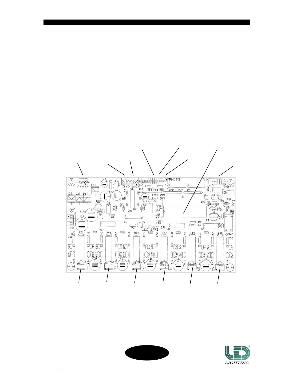
PROBLEMS AND SOLUTIONS
BOARD MS06 (Fig. 8)
MOTORS PC BOARD
COLOURS ROTATING
GOBOS
SHUTTER
MAINS INPUT
MOTORS
MICRO-CONTROL
COLOURS
SENSOR
ROTATING GOBOS
SENSOR
• If one of the Stepper Motors does not move (i.e. the ROTATING GOBO wheel):
1) put off the projector and disconnect the connecting cables of the ROTATING GOBO and COLOUR wheels.
2) connect the cable of the ROTATING GOBO wheel to the connector of the COLOUR wheel.
3) start on the projector:
3a) if the motor of the ROTATING GOBO wheel works properly, it is necessary to replace U16 (PBL3771).
3b) if the ROTATING GOBO motor still does not work, it is necessary to carefully check it, so as all the
connections circuits (cable and connectors).
TILTPAN
DMX INPUT
TROUBLESHOOTROUBLESHOO
TROUBLESHOOTROUBLESHOO
TROUBLESHOO
TINGTING
TINGTING
TING
SC-12/R
CODE 991247
FIXED
GOBOS
ROTATING GOBOS
SENSOR
PRISM
ROT. GOBOS
Page 17
16
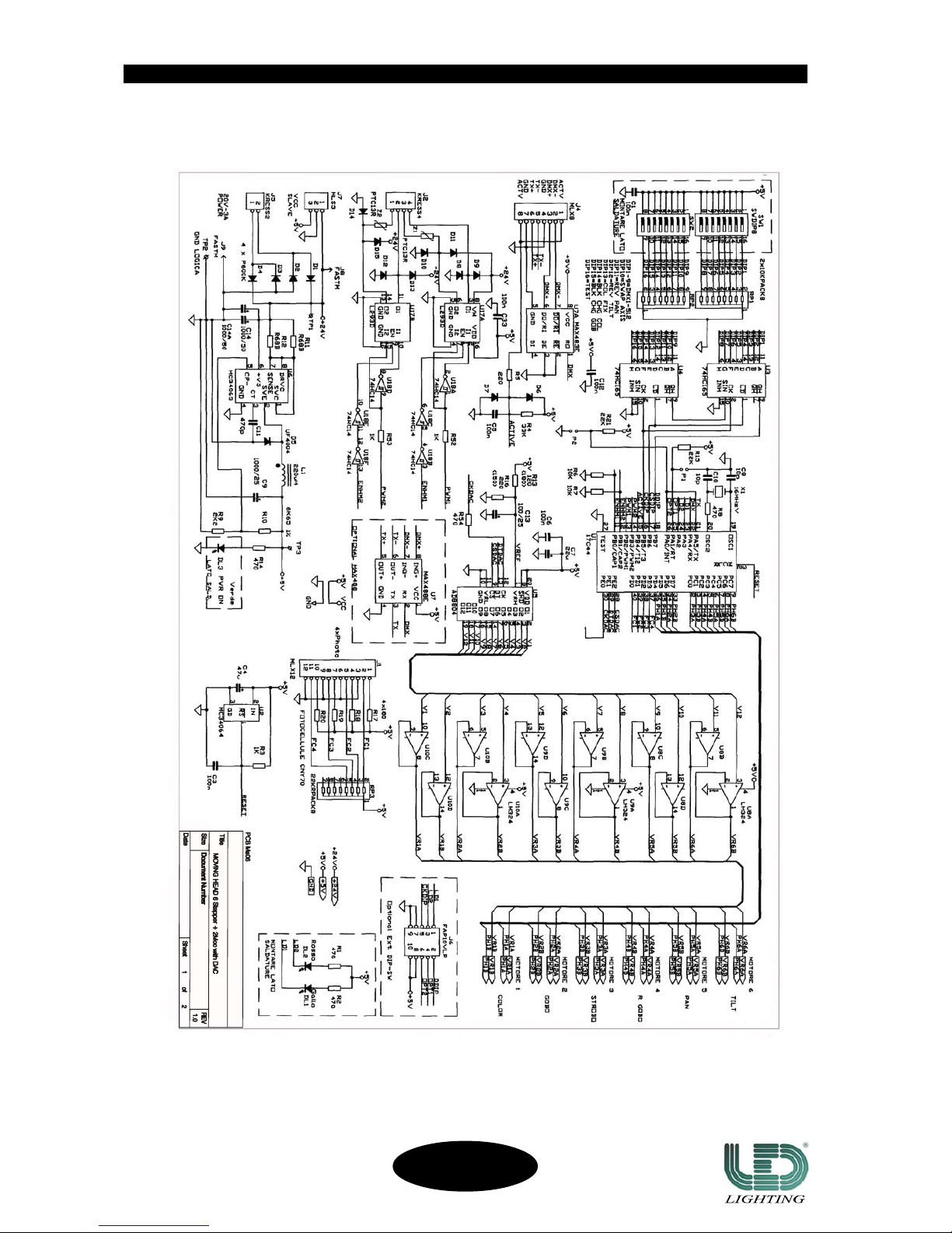
ELECTRICAL SCHEMES
•MS06•
TROUBLESHOOTROUBLESHOO
TROUBLESHOOTROUBLESHOO
TROUBLESHOO
TINGTING
TINGTING
TING
SC-12/R
CODE 991247
Page 18
17
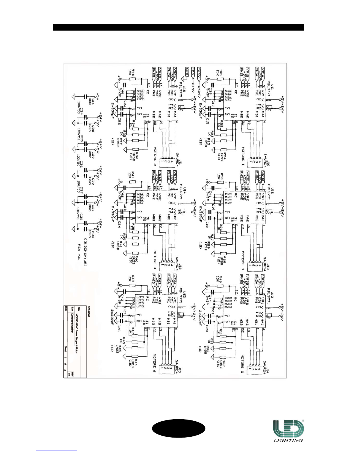
•MS06•
TROUBLESHOOTROUBLESHOO
TROUBLESHOOTROUBLESHOO
TROUBLESHOO
TINGTING
TINGTING
TING
SC-12/R
CODE 991247
Page 19
APPENDIX “APPENDIX “
APPENDIX “APPENDIX “
APPENDIX “
AA
AA
A
””
””
”
18
DMX CHANNELS FUNCTIONS
DMX channels functions complete list (8 ch. - page 12).
MAINTENANCEMAINTENANCE
MAINTENANCEMAINTENANCE
MAINTENANCE
SC-12/R
CODE 991247
For operating a correct maintenance of the SC-12/R follow these instructions:
1) Periodically clean the in/out air grates;
2) Periodically clean the lenses, the dichroic filters and the mirror using antistatic cloths and products.
3) Periodically lubricate the gears of the ROTATING GOBO and COLOUR wheels and of the PRISM support.
! Do not absolutely use solvents or abrasive products.
XMDXMD
XMD
XMDXMD
LENNAHC
NOITCNUFNOITCNUF
NOITCNUF
NOITCNUFNOITCNUF NOITPIRCSEDNOITPIRCSED
NOITPIRCSED
NOITPIRCSEDNOITPIRCSED LAMICEDLAMICED
LAMICED
LAMICEDLAMICED EGATNECREPEGATNECREP
EGATNECREP
EGATNECREPEGATNECREP
1 MSIRPMSIRP
MSIRP
MSIRPMSIRP
AMSIRPAMSIRP
AMSIRP
AMSIRPAMSIRP
TUOAMSIRP
DEPPOTSAMSIRP
MSIRPGNITATOR
51..00
13..61
552..23
%50..%00
%21..%60
%001..%31
2
+SRUOLOC+SRUOLOC
+SRUOLOC
+SRUOLOC+SRUOLOC
WOBNIAR
LEEHWRUOLOCLEEHWRUOLOC
LEEHWRUOLOC
LEEHWRUOLOCLEEHWRUOLOC
ARUOLOC
BRUOLOC
CRUOLOC
DRUOLOC
ERUOLOC
FRUOLOC
GRUOLOC
HRUOLOC
IRUOLOC
LRUOLOC
)deeps61(WOBNIAR
510..000
130..610
740..230
360..840
970..460
590..080
111..690
721..211
341..821
951..441
552..061
%60..%00
%21..%70
%81..%31
%52..%91
%13..%62
%73..%23
%34..%83
%05..%44
%65..%15
%26..%75
%001..%36
3
SOBOGGNITATORSOBOGGNITATOR
SOBOGGNITATOR
SOBOGGNITATORSOBOGGNITATOR
WOBNIAR+
LEEHWOBOGGNITATORLEEHWOBOGGNITATOR
LEEHWOBOGGNITATOR
LEEHWOBOGGNITATORLEEHWOBOGGNITATOR
AOBOG
BOBOG
COBOG
DOBOG
EOBOG
FOBOG
GOBOG
)DEEPS61(WOBNIAR
220..000
540..320
860..640
190..960
411..290
731..511
951..831
552..061
%90..%00
%81..%01
%72..%91
%63..%82
%54..%73
%45..%64
%26..%55
%001..%36
4
EBORTS/RETTUHSEBORTS/RETTUHS
EBORTS/RETTUHS
EBORTS/RETTUHSEBORTS/RETTUHS
DEEPS
EBORTSEBORTS
EBORTS
EBORTSEBORTS
ESOLC
)NIM(1DEEPS
2DEEPS
3DEEPS
4DEEPS
5DEEPS
6DEEPS
7DEEPS
8DEEPS
9DEEPS
01DEEPS
11DEEPS
21DEEPS
31DEEPS
41DEEPS
)XAM(51DEEPS
NEPO
51..00
03..61
54..13
06..64
57..16
09..67
501..19
021..601
531..121
051..631
561..151
081..661
591..181
012..691
522..112
042..622
552..142
%50..%00
%11..%60
%71..%21
%32..%81
%92..%42
%53..%03
%14..%63
%74..%24
%25..%84
%85..%35
%46..%95
%07..%56
%67..%17
%28..%77
%88..%38
%49..%98
%001..%59
Page 20
19
SC-12/R
CODE 991247
APPENDIX “APPENDIX “
APPENDIX “APPENDIX “
APPENDIX “
AA
AA
A
””
””
”
XMDXMD
XMD
XMDXMD
LENNAHC
NOITCNUFNOITCNUF
NOITCNUF
NOITCNUFNOITCNUF NOITPIRCSEDNOITPIRCSED
NOITPIRCSED
NOITPIRCSEDNOITPIRCSED LAMICEDLAMICED
LAMICED
LAMICEDLAMICED EGATNECREPEGATNECREP
EGATNECREP
EGATNECREPEGATNECREP
5 ESRAOCNAPESRAOCNAP
ESRAOCNAP
ESRAOCNAPESRAOCNAP
TIB8GNINOITISOPESRAOCTIB8GNINOITISOPESRAOC
TIB8GNINOITISOPESRAOC
TIB8GNINOITISOPESRAOCTIB8GNINOITISOPESRAOC
°081
552..000%001..%00
6 ESRAOCTLITESRAOCTLIT
ESRAOCTLIT
ESRAOCTLITESRAOCTLIT
TIB8GNINOITISOPESRAOCTIB8GNINOITISOPESRAOC
TIB8GNINOITISOPESRAOC
TIB8GNINOITISOPESRAOCTIB8GNINOITISOPESRAOC
°04
552..000%001..%00
7 NOITATORSOBOGNOITATORSOBOG
NOITATORSOBOG
NOITATORSOBOGNOITATORSOBOG
POTS
NOITATORTHGIROTTFEL
POTS
NOITATORTFELOTTHGIR
POTS
50..00
521..60
921..621
942..031
552..052
%10..%00
%94..%20
%15..%05
%79..%25
%001..%89
8
SOBOGDEXIFSOBOGDEXIF
SOBOGDEXIF
SOBOGDEXIFSOBOGDEXIF
WOBNIAR+
LEEHWSOBOGDEXIFLEEHWSOBOGDEXIF
LEEHWSOBOGDEXIF
LEEHWSOBOGDEXIFLEEHWSOBOGDEXIF
AOBOG
BOBOG
COBOG
DOBOG
EOBOG
FOBOG
GOBOG
HOBOG
IOBOG
LOBOG
)DEEPS61(WOBNIAR
510..000
130..610
740..230
360..840
970..460
590..080
111..690
721..211
341..821
951..441
552..061
%60..%00
%21..%70
%81..%31
%52..%91
%13..%62
%73..%23
%34..%83
%05..%44
%65..%15
%26..%75
%001..%36
Page 21

NONO
NONO
NO
TESTES
TESTES
TES
20
SC-12/R
CODE 991247
Page 22

Working to make its products always more perfect, LED reserves the possibility to make technical changes during the production. The technical features and the drawings on this
manual are not binding for LED and they could be changed at any time without notice. LED it is not responsible for any inconvenience caused by an improper or different use of
the unit respect to the one for what it has been made.
LED s.r.l. : ZONA P.I.P. Contrada Pozzillo - Viale Saponaro D. Lotto G, N. 8 - 70016 Noicattaro (BA) - Italy
Tel. : +39/080 9906090 Fax. : +39/080 9906092/3
Web Site : www.ledsrl.it e-mail : [email protected]
Rev. 12/2005
 Loading...