

Page 1

IES Series
Industrial Ethernet Switch
User Guide
Model: IES-2205, IES-2206, IES-2208, IES-2216,
IES-2210, IES-2220
July, 2011
Version:1.0
IES Series User Manu al V. 1.0
Page 2

ii
NOTICE
L-com Global Connectivity reserves the right to make changes in specifications and other information contained in this
document and its web site without prior notice. The reader should in all cases consult L-com Global Connectivity to determine
whether any such changes have been made. The hardware, firmware, or software described in this document is subject to
change without notice.
IN NO EVENT SHALL L-COM GLOBAL CONNECTIVITY BE LIABLE FOR ANY INCIDENTAL, INDIRECT, SPECIAL,
OR CONSEQUENTIAL DAMAGES WHATSOEVER (INCLUDI NG BUT NOT LIMITED TO LOST PROFITS)
ARISING OUT OF OR RELATED T O THIS DOCUMENT, WEB SITE, OR THE INFORMATION CONT AINED IN
THEM, EVEN IF L-COM GLOBAL CONNECTIVITY HAS BEEN ADVISED OF, KNEW OF, OR SHOULD HAVE KNOWN
OF, THE POSSIBILITY OF SUCH DAMAGES.
L-com Global Connectivity, Inc.
45 Beechwood Drive
North Andover, MA
01845
2011 L-com Global Connectivity, Inc. All rights reserved.
FCC NOTICE
This device complies with Part 15 of the FCC rules. Operation is subject to the following two conditions: (1) this device
may not cause harmful interference, and (2) this device must accept any interference received, including interference that
may cause undesired operation.
NOTE: This equipment has been tested and found to comply with the limits for a class A digital device, pursuant to Part
15 of the FCC rules. These limits are designed to provide reasonable protection against harmful interference when the
equipment is operated in a commercial environment. This equipment uses, generates, and can radiate radio frequency
energy and if not installed in accordance with the operator’s manual, may cause harmful interference to radio
communications. Operation of this equipment in a residential area is likely to cause interference in which case the user
will be required to correct the interference at their own expense.
WARNING: Changes or modifications made to this device which are not expressly approved by the party responsible for
compliance could void the user’s authority to operate the equipment.
IES Series User Manu al V. 1.0
Page 3

iii
SAFETY PROVISIONS
Please read this user manual thoroughly before installing the IES switch
Do not place equipment in or around water
Keep power line connections clear
Do not let power lines touch or contact each other
Verify power requirements of all attached devices prior to installation
Keep optical fiber ports clear of debris
Do not attempt to open and service this product yourself
Some fiber switches use laser powered optical transceivers that can cause permanent eye damage if directly viewed with the
eye or with optical instruments. DO NOT view the optical fiber ports when the product is in use.
IES Series User Manu al V. 1.0
Page 4

Contents
Chapter 1 Introduction ................................................................................................................................................. 5
1.1 System Parameters ............................................................................................................................................. 6
Chapter 2 Hardware functionality ............................................................................................................................. 7
2.1 Main functions ...................................................................................................................................................... 7
2.1.1 Front Panel Interfaces ........................................................................................................................... 7
2.1.2 Power Input Interface and Installati on ................................................................................................. 7
2.1.3 Relay option ............................................................................................................................................ 8
2.1.4 LED indication lights ............................................................................................................................... 9
Chapter 3 Hardware installation .............................................................................................................................. 10
3.1 DIN-Rail installat i on ........................................................................................................................................... 10
Chapter 4 Support and Warranty ............................................................................................................................. 11
4.1 Support ................................................................................................................................................................ 11
4.2 Warranty .............................................................................................................................................................. 11
IES Series User Manu al V. 1.0
Page 5

5
Chapter 1 Introduction
1.1 10/100TX (100FX) Ethernet Switches
The IES series Industrial Ethernet switches provide 10/100TX (100FX some models) Full Duplex Ethernet
connectivity to Ethernet enabled devices in harsh environments. All switches in this series are DIN rail
mountable using standard 35mm DIN rail and require 24V DC power for operation. The IES series is perfect
for designing and building new industrial IP networks or adding to existing Industrial LAN infrastructure.
These switches utilize standards based Ethernet and are compatible with all other IEEE803.3/802.3u
compliant devices such as PLC’s , med ia converters as well as IP enable d, m eters, valves, and driv es.
1.2 Features
• 10Base-T/100Base-TX adaptive port(Full/Half duplex)
• Auto connection with MDI/ M DI-X
• 100Base-FX Full duplex Single mode or Multimode fiber options
• Broadcast S tor m Protectio n
• Redundant 24V DC power inputs (except IES-2205)
• Reliable protection from EMC and against over-current / over-voltage.
• Ribbed heat-removal case design
• Fan less design( extends MTB F)
• DIN-Rail mounting
1.3 Product packing list
IES Series switches includes the following items:
• IES Series Ethernet Switch
• User Manual
IES Series User Manu al V. 1.0
Page 6

6
1.1 System Parameters
Configurations
Switch parameters
RJ45 port parameters
Optical port parameters
Power parameters
Dimensions
Weight
Temperature
IES Series User Manu al V. 1.0
IES-2205 5 10/100TX
IES-2208 8 10/100TX
IES-2216 16 10/100TX
IES-2206-M2 4 10/100TX, 2 100FX Multimode 2km
IES-2206-S20 410/100TX, 2 100FX Single mode 20km
IES-2206-S40 4 10/100TX, 2 100FX Single mode 40km
IES-2206-S60 4 10/100TX, 2 100FX Single mode 60km
IES-2206-S80 4 10/100TX, 2 100FX Single mode 80km
IES-2210-M2 8 10/100TX, 2 100FX Multimode 2km
IES-2210-S20 8 10/100TX, 2 100FX Single mode 20km
IES-2210-S40 8 10/100TX, 2 100FX Single mode 40km
IES-2210-S60 8 10/100TX, 2 100FX Single mode 60km
IES-2210-S80 8 10/100TX, 2 100FX Single mode 80km
IES-2220-M2 16 10/100TX, 2 100FX Multimode 2km
IES-2220-S20 16 10/100TX , 2 100FX Single mode 20k m
IES-2220-S40 16 10/100TX , 2 100FX Single mode 40k m
IES-2220-S60 16 10/100TX , 2 100FX Single mode 60km
IES-2220-S80 16 10/100TX , 2 100FX Single mode 80k m
Standards:IEEE 802.3,IEEE 802.3u,IEEE 802.3x
Store-and-Forward mode rate:148,880pps
MAC address table size:1K
Bridging method:Store-and-forward mode
Physical:RJ45 Jack(shielded)
Speed:10Base-T/100Base-TX,auto-negotiation
Standards: IEEE802.3/802.3u
Communication distance:<100m
Link Budget:
>-12dBm(Single mode fiber) >-17dBm(Multimode fiber)
RX Sensitivity:
<-38dBm(Single mode fiber) <-35dBm(Multimode
fiber)
Wavelength:
1310nm(Single mode fiber) 1550nm(Single mode fiber
60km and 80km)
1310 nm(Multimode fiber)
Typical Distance:
20~80Km(Single mode fiber) <5Km(Multi mode fiber)
Optical port type: Duplex SC
Transport rate: 125Mbps
Input Voltage:12-36V DC
Input expend: IES-2205, IES-2206, IES-2208 <5W
IES-2210, IES-2216, IES-2220 <15W
Voltage passing:Inside
IES-2205 1.30” W x 3.17” D x 4.5”H
IES-2208, IES-2206 Series 1.30” W x 3.85” D x 5.7”H
IES-2210 Series 2.13”W X 4.35”D x 5.70”H
IES-2216, IES-2220 Series 2.84”W x 4.33”D x 5.70”H
IES-2205 .75 lbs
IES-2208, IES-2206 .95 lbs
IES-2210 Series 1.40 lbs
IES-2216, IES-2220 Series 2.00 lbs
Operating Temp:-40℃~+70℃
Storage Temp:-45℃~+85℃
Ambient Relative Humidity:0~95%(non-condensing)
Page 7
7
Chapter 2 Hardware functionality
2.1 Main functions
2.1.1 Front Panel Interfaces
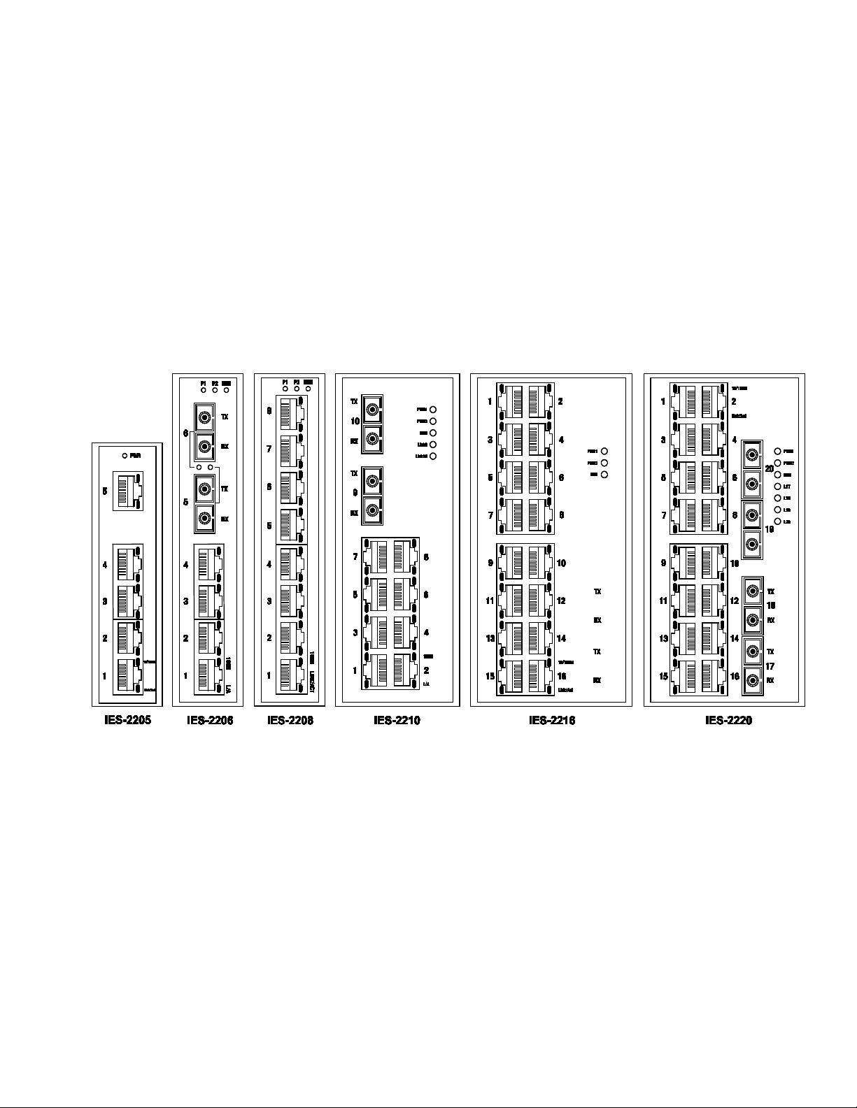
The IES series encompasses a variety of port configuration options supporting both copper Category rated
cabling as well as Multimode and Single mode fiber optic cabling. The schematic below outlines the front
panel configuratio ns of L-com’s IES series. See figure 2-1.
Fig. 2-1
2.1.2 Power Input Interface and Installation
Power T er mi nal Block
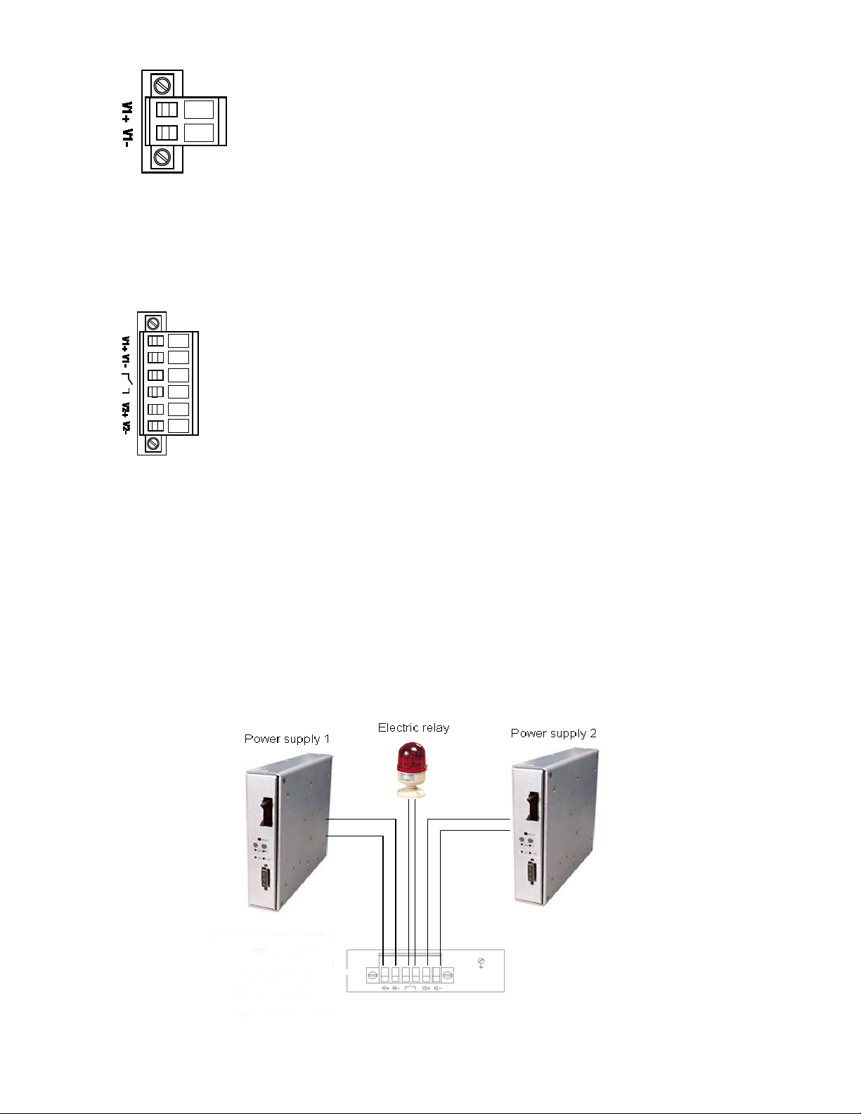
The IES-2205 features a single 24V DC power in put with one V+ power anode and one V- power cathode.
See
Figure 2-2.
IES Series User Manu al V. 1.0
Page 8
8
Fig. 2-2
The IES-2206, IES-2208, IES-2216, IES-2210, and IES-2220 all feature redundant power connectors with dual
power anodes and V- power cathodes. See Figure 2-3.
Fig. 2-3
When using only one power supply make sure to connect the supply to the V1+ and V1- terminals.
Power conductor diameter should be less than 1.5mm to fit the screw terminals.
V+
2.1.3 Relay option
Additionally, a dry contact relay connection is available. In the event of a power supply failure, you can attach
an audible or visual alarm such as a Klaxon to the relay to alert plant personnel a power supply has failed.
This feature works with a sing le or dual power supply config ur at ion. See Figure 2-4
Fig. 2-4
IES Series User Manu al V. 1.0
Page 9

9
LED
Lights
Status
Interface LED Status
The switch is operational and functioning
Optical Port LED Status
On
FX port’s 100 Mbps link is active
RJ45 Port LED Status
On
Off
RJ45 port’s 10 Mbps link is inactive.
To connect power to the switch first make sure the AC/DC power supply is NOT connected to an AC power
outlet. Connect the + and – conductors from the AC/DC power supply to the V1+ and V1- terminals
respectively. If a redundant DC power configuration is to be used connect the second set of conductors to
V2+ and V2- respectively.
Grounding
Be sure to properly ground the IES switch. Failure to properly ground the switch may result in damage or
destruction of the switch or attached devices.
2.1.4 LED indication lights
The front panels of the IES Series Industrial Ethernet Switches feature LED indicators which aid in
troubleshooting and v iew i ng the system status at a gla nc e. See Figure 2-5.
Fig. 2-5
PWR
RUN
LINK
10M/
100M
(Yellow)
LNK/ACT
(Green)
On Power is being supplied to the switch
Off Power is not being supplied to the switch
On
Off
Blinking
Off 100BaseFX port’s link is inactive.
Off
On RJ45 port’s 10Mbps link is active
Blinking
properly
The switch has a malfunction(after power is
applied)
Data is being transmitted at 100Mbps.
100Mbps Operation (100Base-TX)
10Mbps Operation(10Base-T)
Data is being transmitted at 10Mbps
IES Series User Manu al V. 1.0
Page 10
10
Chapter 3 Hardware installation
3.1 DIN-Rail installation
Most industrial areas choose 35mm DIN-Rail installation. The DIN-Rail attachment plate is fixed to the rear panel
of the IES Switch when you take it out of the box. If you need to reattach the plate to the switch, make sure the
DIN-Rail bracket is situated towards the top.
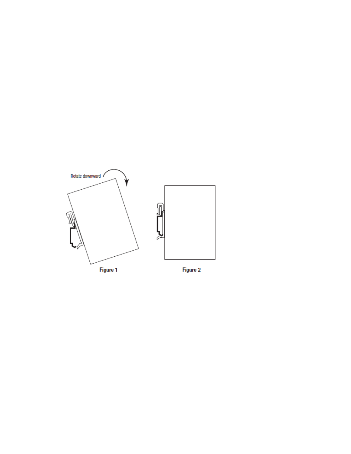
• Insert DIN-Rail into the DI N-Rail slot of the IES Switch and rotate
downward as shown in Figure 1.
• Snap the Media IES Switch firmly into place onto the DIN-Rail as shown in Figure 3-1.
Fig. 3-1
IES Series User Manu al V. 1.0
Page 11

11
Chapter 4 Support and Warranty
4.1 Support
Should you require support for your IES switch please contact the L-com Product Support team via one of the following
methods.
__________________________________________________________________________________________
Phone
1-978-682-6936 Toll Free 1-800-341-5266
e-mail [email protected]
4.2 Warranty
We warra nt these IES Industrial Ethernet Switches for a period of three years from time of purchase. These products are
warranted against defects in workmanship or materials under normal use. We cannot warranty our products in case of misuse,
acts of God, or consequential damage. Alteration of product cancels all warranties. Under no circumstances will we be
responsible for any damage beyond the replacement cost of the defective merchandise. We reserve the right to repair or
replace any products that are returned under warranty. Products distributed by us carry the warranty of the respective
manufacturer only. Good s ma nufa cture d by us to meet Buyer’s instructi ons , specifications or requirements are subject to a plus
or minus deviation of five percent (5%) in quantity. This warranty applies to the original purchaser only and is not transferable.
This limited warranty covers normal use. The limited warranty does not cover damage incurred during shipment, caused by
impact with other objects, dropping, immersion in liquid; service by anyone other than us, use not in accordance with
instructions, accident, abuse, misuse, natural disasters such as flood, fire, earthquake or lightning, power surges and problems
caused by use of power supplies not supplied by us. Warranty coverage will not apply in the event the serial number or
brand-name has been removed, altered or defaced. EXCEPT AND TO THE EXTENT EXPRESSLY SET FORTH ABOVE,
THERE ARE NO WARRANTIES, EXPRESS OR IMPLIED, INCLUDING, BUT NOT LIMITED TO, ANY W ARRANTIES OF
MERCHANTABILITY OR FITNESS FOR A PARTICULAR PURPOSE AND WE EXPRESSLY DISCLAIM ALL WARRANTIES
NOT STATED HEREIN. Some states do not allow the exclusion of implied warranties or limitations on how long an implied
warranty lasts, so the above limitation may not apply to you. This warranty gives you specific legal rights, and you may also
have other rights that vary from state to state.
IES Series User Manu al V. 1.0
 Loading...