

Building instruction for ZAPsolute Mk4.1 V.2.0
Misc. information.
The two channels have to be mechanically separated in order for the amplifier to fit into the casing.
The frontpanel is prepared for a display unit, you will automaticly receive when it is developed. Until
then we suggest You mount some LED’s behind the window. You can set modes using the switches
on the rear panel.
Tools.
Bitscrewdriver or screw machine.
T6 bit ( or T6 screwdriver ).
T10 bit.
T20 bit.
Cutter (small model).
Component bending tool with 4, 5 and 8 modules (0,1”).
Soldering iron, normal tip.
Screwdriver with a straight 2-4 mm. Head.
Multimeter with mV range.
Wrenches with 7, 8 10, 12 and 14 mm. Gaps or adjustable gap.
Crimptool (as used for auto works).
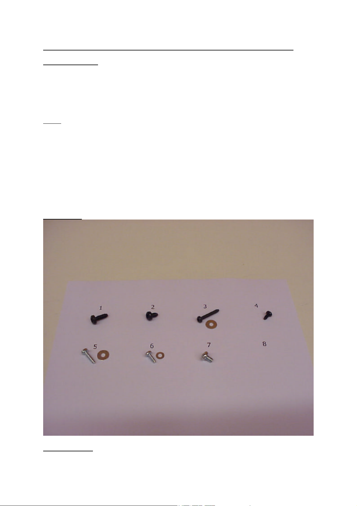
Screw types.
Mounting guide:

1..Start by mounting all the low parts, and jumper pins ( 2 golden pins with black plastic holder).
Mount RGND ion both channels ( 2R2 red red black silver brown, 5 modules )
Mount RZ+ and RZ- in both channels ( 2k0 red black black brown brown, 5 modules )
Resistors can be turned anyway desirable, but it looks nicer if all
Turn the same way. RZ+ and RZ- determine the input impedance, You may
Want to use another value than posted here. Look later in this paper.
Mount 12 pcs. 0R27 1W des. RE1- RE6 in both channels. ( 0R27 = red violet silver
gold, 8 modules )
Mount the optocoupler in both channles, it fits next to the 500R BIAS trimmer.
The optocoupler is a small 4 pin ’IC’ marked SHARP PC817.
The round dot should be farthest away from the heatsink.
Mount P1 ( BIAS trimmer ) in both channels. It is a 500 Ohm value, marked 501.
Mount P2 ( DC trimmer ) in both channels, it is 10 k value marked 103.
Mount D309-D316 and D409-D416 all BYV36E, looks like a grey pearl on a wire,
With a black line marking. This marking should fit with the
Printing on the PCB IMPORTANT, all the diodes should be
Oriented in the same direction, as printed.
4 modules.
Mount R301 - R320 (interrupted line of numbers) and R401-R416 total of 32 power
Resistors value 0,1 Ohm on power supply board. They are black ceramic
Parts with marking DALE (Vishay) printed on them. 8 modules.
These resistors are a little wider than the PCB symbol, but will fit in easily.
Mount C313, C314, C413 and C414, 1uF 250 V MKT, Dark Gray plastic component
marked 1K 250. This is a non polar component.
Mount the two relays, near the input terminals, at rear end of each channel’s PCB.
Turn the relay in the direction that the line on the component fits
The line on the PCB symbol.
Mount T9, BC517 in both channels. It is to be located right between the two driver
Transistors, and the output transistors, at the heatsink edge of the PCB.The flat side
of BC517 goes towards the PCB edge. Mount BC517 as high as the pins allow.
Mount C134 and C234, 1uF MKT (light blue color). Non polar component.
Mount jumpers. A jumper consist of two golden pins held together by a black plastic
intersection.
In the standard setup You always have to short the jumper ’Protection’
So You might want to just jump it with a soldered wire. If You choose to
mount the jumper, it gives You the option to disconnect the protection function. (Not
recommended).
Mounting the jumper ’DC Servo’ is a very good idea, because You might need
to Switch this function in and out for adjustments.
The ’S.A.’ jumper stands for Stand Alone. You only need to short this jumper if
You want to break off the controller board, and run the ZAP as a clean
Amplifier with no control functions. Usually not used.
The ’Auto’ jumper places the ZAPsolute in constant ’Auto Power Down’ mode.
This means that when You listen to music, the amp runs in pure Class A, but
After 5 minutes without music, it automaticly switches the bias current down to
A power saving mode. Normally You would place a switch on the rear panel to
Control Class A / Powerdown mode, so You dont need to mount the ’Auto’
Jumper, if this is what You want.
So if You want to take any future setup possibility into account, mount all the
jumpers, else just mount the most likely one: ’DC Servo’ and short out the
’Protection’ with a soldered wire.
Mount the 4 screwterminal blocks. They fit in between the dark gray 1K250 capacitors,
You mounted a few minutes ago. Remember the holes for wire connection (For the
transformers) should go towards the edge of the PCB.
Screw the M4 X 18 mm. Spacers onto the power supply PCB, using screw no. 7. There
must be no short between any screw or spacer and a PCB soldering or wire end.
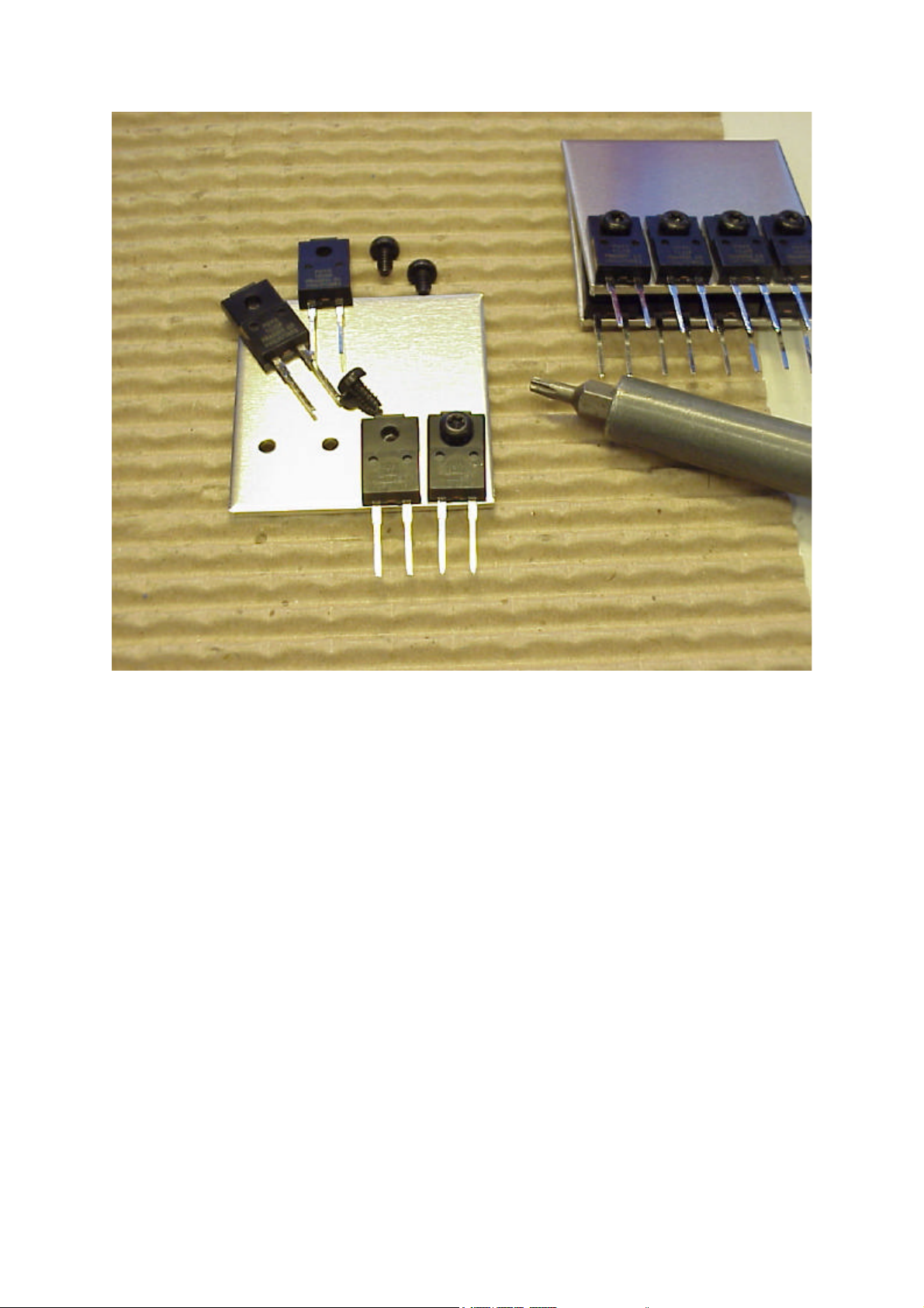
Mount the output transistors, drivers and predrivers in the PCB without soldering them
in. The metal sides should go towards the PCB edge, and the text should face the
middle of the PCB. Place the heatsink, close to the output transistors, in the upright
position, with the drilled holes downwards.
Screw on the output transistors, drivers and predrivers, so the distance from the PCB underside to
the
Table underneath is similar to the metal spacers mounted on the PCB.
Remember to use insulation pads (orange Kapton sheets) on the output transistors.
Check for any impurities between the transistor, the Kapton pads
and the heatsink. No heatsink compound should be applied, it is already impregnated
on the kapton sheets.
Tighten the screws good, of course without breaking them.
Use screw no. 6 for the small drivers, no. 3 for the big drivers and midst
Hole in the output devices ( SANKEN), and no. 5 for the output devices
Side holes. All screwholes have to be used, none must be left unfastened!
Should You break a screw it is very important that You remove the broken piece from the heatsink,
and apply a new screw. This is easily done by removing all transistors, and kapton sheets, and then
with an old
Cutter turning the broken screw counter clockwise.
The long no. 3 screws are used to fasten the drivers to the output devices. If Your Mk4 is bigger than
50 Watts, a small heatsink plate should be mounted between drivers and output devices. In this case
remember to use mica sheets for isolation, heatsink compound is allowable but not nessescary.
Solder all the power transistors, check that the heatsink is precisely 90 degree angled to the PCB.
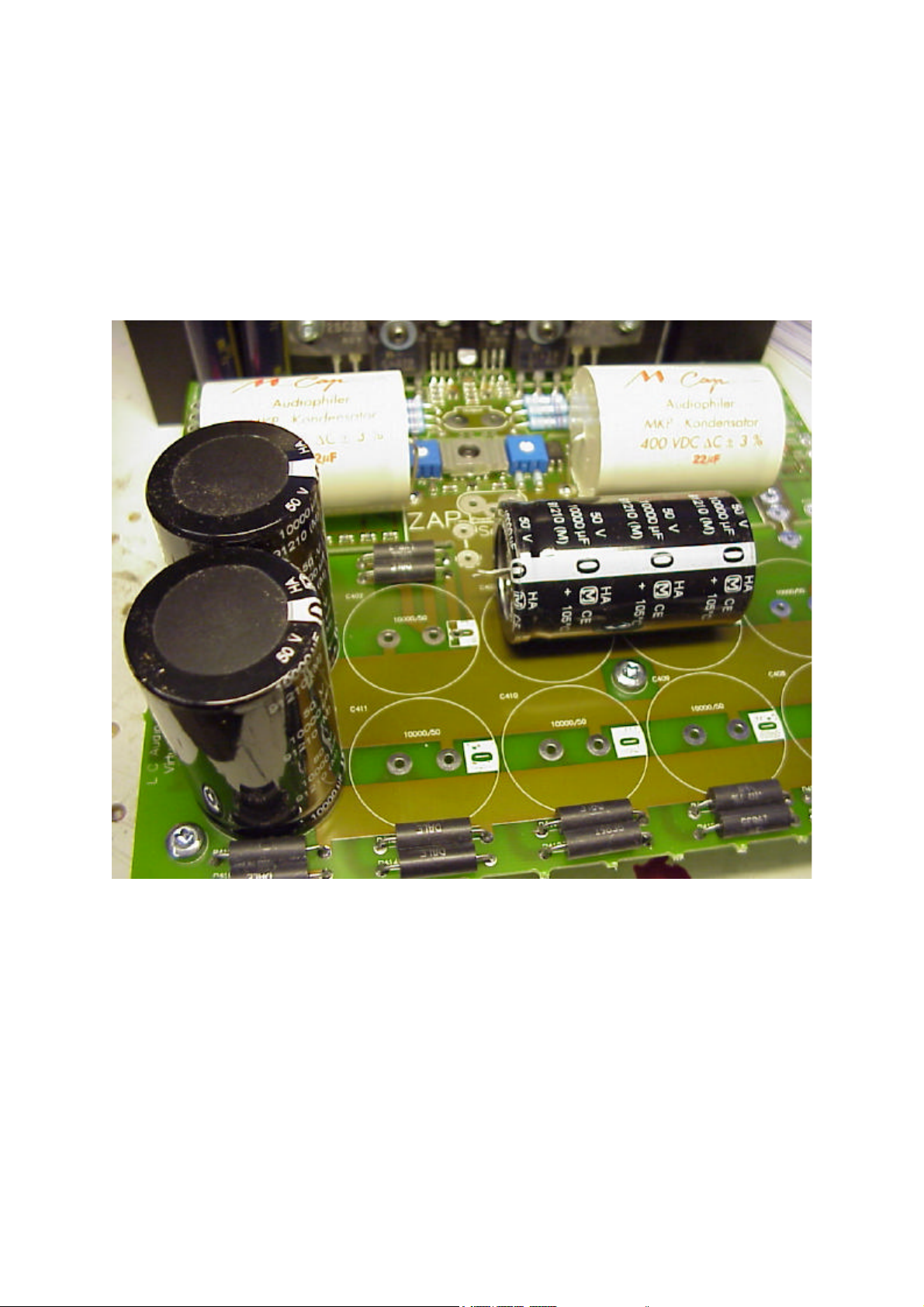
Mount the 4 pcs. 22 uF MCAP capacitors. They can be easily mounted from the top side of the PCB.
Mount the other larger components, remember to polarize the 10000 uF / 50 V electrolytics as shown
on the PCB symbols. Failing to do so, may cause small explosion of the electrolytic.
Mount the 16 Schottky Rectifiers on their heatsinks, remember to remove the plastic liner from the
aluminum plate before fastening any diodes. Fit the rectifiers neatly, so the will slide into the PCB
With no bending of the pins. All the rectifiers should be mounted so they are visible from the
Screw terminal side, the heatsinks should be closer to the electrolytic capacitors.
Mount the ULC heatsinks on top of the SMD transistors, between the two blue preset resistors. The
screw should be mounted from the top side of the PCB not the bottom side. Tighten until the
heatsink presses a little against the transistors, no more.

Now mount the input / output wiring, and switch wires.
Place rubber feet on the corners of the bottom plate. (the one the most holes in it)
Fasten the heatsinks to the bottom plate, using screw no. 1 for the heatsinks themselves, and no. 7
for the metal spacers. Wait with the tightening of any screws, until all screw have caught their rivets.
Also fasten any unused heatsinks, or extension heatsinks using screw no. 1.

Mount the terminals on the rear panel.
All holes are made to fit to the terminals, use screw no. 4 for the XLR receptors. The PUSH button
should go upwards.
The white (Gnd) speaker terminal is placed nearest the RCA plugs.
The Fuse holder of the mains entry, goes downwards.
Fasten the back panel to the bottom plate using screws no. 1.
Connect the wires from the PCB.

Mount brackets and front glass to the front plate.
Use screw no. 2 for the brackets, and no. 4 for the front glass, be careful not to overtighten the front
glass screws. A ’squeek’ will sound when they are fastened properly.
Fasten the front panel to the bottom plate using screws type 1.
When mounting the transformers on the bottom plate, it is important You use rubberplates both
under and over the transformer. If You dont the metal plate will cut through the insulation causing a
short circuit.
The larger transformers should be connected to the ’MAIN’ screwterminals, the smaller transformer
goes into the ’AUX’ terminals. If the main transformers have uninsulated ends longer than 10 mm.
They should be cropped to about 8 mm. Length. Use an old one, instead of You brand new
Lindstrom 8140 ultra flush cutter.
Mount the transformer wires in the following order from left to right:
Yellow - Orange - Red - Black
Applies to both MAIN and AUX transformers. Some AUX transformers brand name ’PETRA’ have
different
Color codes:
Yellow - Green - Pink - Black
The AUX transformers should not be tightened to hard in the terminals, as this may cause the wires
to break.
Mount the primary wires (brown and blue) to the mains DC filter. All Brown ones in one ’out’ post,
and all blue ones in the other one. Put the thin wires in first, it makes it a lot easier!
Connect the two ’in’ posts to the mains inlet so the brown transformer leads end up being hooked to
the ’L’ terminal on the inlet, and the blue ones to the ’N’.
If You do not have a dual mono version with a total of 4 transformers, You should now connect each

of the three pads on the power supply PCB, just beside the rectifiers, to the corresponding pad on
the other channel. No mirroring!

Fasten the DC filter to a heatsink as shown, it should be very secure, and the capoacitor must NOT
be able to touch any cabinet part, when You put the lid on the case. You can tighten the spacer by
holding the screw in the groove with a screwdriver while turning the spacer with a wrench. Then at
last You tighten the screw holding the filter PCB.
Fit a fuse into the mains inlet, use a 4 AT if You have one main transformer, and a 8 AT if You have
two. Main transformers. Connect a wire from the mains switch to the mains inlet as shown here:
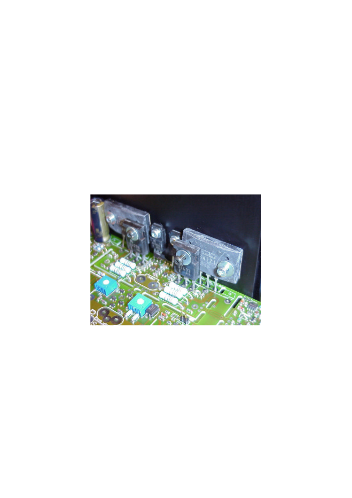
Adjusting BIAS current.
Put You test leads into the holes just beside the 0R27 emitter resistors as shown on the photo

Apply mains power to the inlet.
Adjust BIAS preset to :
50W version 250 mV
78W version 191 mV (also dual mono version)
118W version 112 mV
Wait some 20 minutes and readjust.
Summary Jumper setup:
Jumper mounted Jumper not mounted
Protection: hort Circuit protection works. Short Circuit Prot NOT
Functional.
DC Servo DC Servo works. DC Servo NOT functional.
S.A. (stand Alone) Control board may be removed. No PCB part may be
removed for
Safe operation.
Auto Always in ’Auto Power Down mode. Mode as set by switch or
always
Pure Class A.
NORMALLY You only mount the ’DC Servo’ jumper and also short out the ’Protection’ jumper.

Power down mode Switch should be connected to the three solder pads underneath the 22 uF
MCAP’s.
Function:
Up: Powerdown constantly.
Middle: Class A constantly.
Down: Autopowerdown.
Input selection.
If You are only going to use one input (RCA or XLR), it is best to connect it to the ’Direct’ input. You
save a set of relay contacts in the signal path.
RCA:
Gnd - Gnd
Hot - ’+’
XLR:
1 - Gnd
2 - ’+’
3 - ’-’
There is also the possibility to switch between RCA and XLR inputs. The primary input (most used) is
connected to ’Primary’ as listed above, while the secondary (least used) is connected to ’Secondary’.
Either input takes both XLR and RCA input signals.
Normally Youlisten to ’Primary’ input, to switch to ’Secondary’ short the two solder pads ’ Input Sel.’
With a switch.
Input impedance.
RZ+ and RZ- determine the input load for + and - inputs..
We have chosen 2k0 since this value works well with most preamps. If You have a Sidewinder
preamp you can benefit from better cable adaption, by reducing RZ+ and RZ- to a lower value like
300 Ohms.
If You have a tupe preamp it is a better idea to increase RZ + and RZ- to say 47 kOhms, but this
calls for a high quality DC blocking capacitor of 1 uF in series with the ’hot’ signal lead. (Some 4 Hz
Fc).
LED’s indicators.
It is fully optional to connect LED’s the ZAP will work even if no LED’s are connected. You are not to
short any unused LED indications.
LED function:
OK All systems GO - Protection not activated.
Cl.A. The Amp. Currently Running in Class A.
Cl.A/B. The Amp. Currently running in Class A/B (Powerdown).
The longer pin of the LED goes into the + terminal, the shorter in -. It is NOT allowed to short all terminals to use a common ground wire to the front LED’s. You always have to connect both + and -

wires to each LED.
Extension Modules.
The Terminal ’NPN Basis’ on the main board is connected to the terminal ’NPN Basis’ on the ext.
Board using a 0,5 sqr mm. wire. (Normally white)
The Terminal ’PNP Basis’ on the main board is connected to the terminal ’PNP Basis’ on the ext.
Board using a 0,5 sqr mm. wire. (Normally white)
Power + on the main board is connected to V+ on the ext. Board with a heavy wire.
Power - on the main board is connected to V- on the ext. Board with a heavy wire.
Power Gnd on the main board is connected to Gnd on the ext. Board with a heavy wire.
BDT63 and 1k0 on the ext. Board should NOT be mounted!

If You are using ext. Boards in a 78 or 118 Watt version, to drive a separate bass output ( the
normal thing to do) You should connect a Zobel Network of a 100 nF / 400 V capacitor and a 2,2
Ohms 1 W resistor from Power Gnd to Output on the bass output ( as shown ). If You do not do this,
using the one output with the other unconnected may cause oscillation, dangerous to the amplifiers
health.
 Loading...