

L.B. White Premier 350, TS350, Premier 350 DF, TS350DF Owner's Manual And Instructions
Attention
This heater has been tested and
evaluated by the CSA Group in
accordance with the requirements
of Standard ANSI Z83.7•CSA 2.14
and is listed and approved as a
ductable direct gas-fi red forced-air
construction heater with
application for the temporary
heating of buildings under
construction, alteration, or repair.
Additionally, this heater has been
application reviewed and approved
by the CSA Group for U.S.and
Canadian Tent Heating
Applications with temporary human
occupancy. CHECK WITH YOUR
LOCAL FIRE SAFETY
AUTHORITY, YOUR LOCAL FUEL
GAS SUPPLIER, OR THE L.B.
WHITE COMPANY IF YOU HAVE
QUESTIONS REGARDING
APPLICATIONS.
www.lbwhite.com
SCAN THIS
with your smartphone or
visit http://goo.gl/5j21G
to view maintenance
videos for L.B.White heaters.*
WORLD PROVIDER - INNOVATIVE HEATING SOLUTIONS
411 Mason Street, Onalaska, WI 54650 • 800-345-7200 • 608-783-5691 • 608-783-6115 (fax) • www.lbwhite.com
Congratulations!
You have purchased the fi nest circulating heater available.
Your new L.B. White heater incorporates the benefi ts from the
most experienced manufacturer of heating products using stateof-the-art technology.
We, at L.B. White, thank you for your confi dence in our products
and welcome any suggestions or comments you may have...
contact us at 1-800-345-7200, or email us at
customerservice@lbwhite.com.
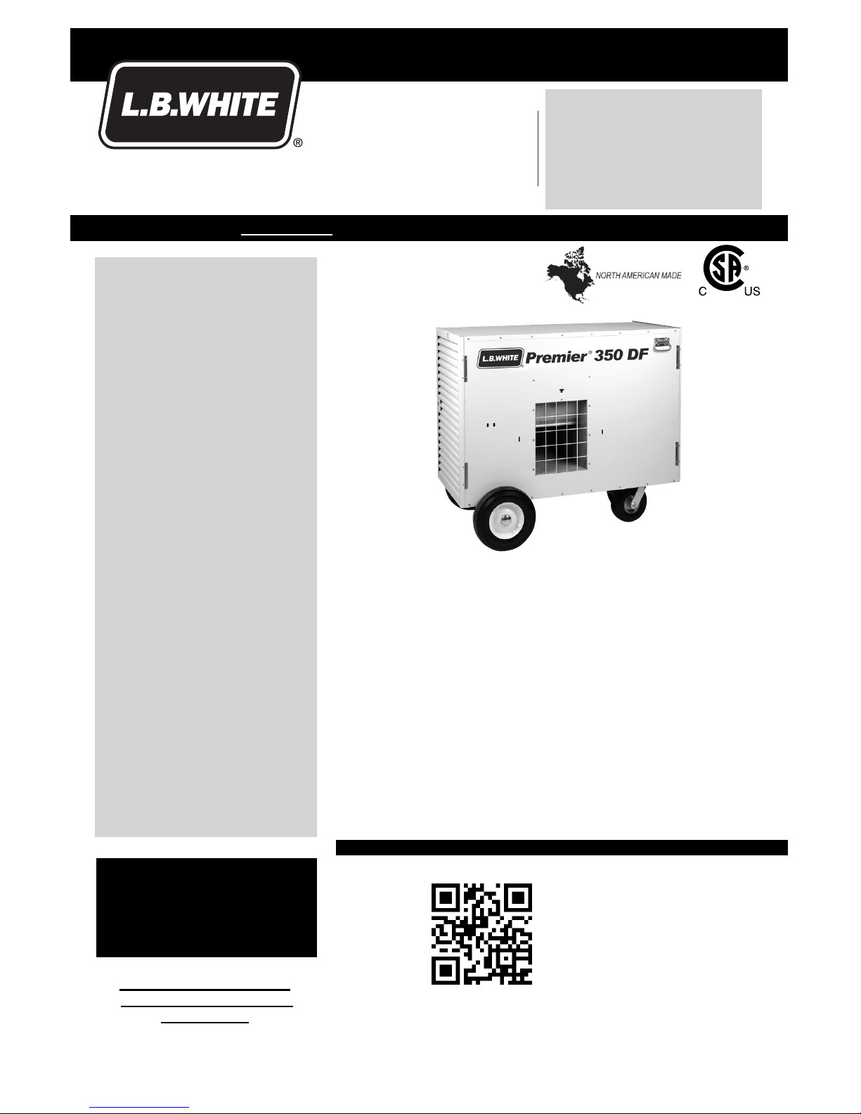
LP Vapor Withdrawal or Dual Fuel
Premier
Ductable Heaters
TS350
TS350DF
350,000 Btuh / 102.6 kW
350,000 Btuh / 102.6 kW
Owner’s Manual and Instructions
View this manual online at www.lbwhite.com
* Requires an app like QR Droid
for Android or for iPhone
SEE ASSEMBLY
INSTRUCTIONS
INSIDE
Please refer to important
elevation information on
inside cover.
Premier Ductable Heaters
www.lbwhite.com
Owner’s Manual • Premier 350
2
TABLE OF CONTENTS
WARNING
Standard products are manufactured to operate at optimum effi ciency at elevations
between 0 and 2000 ft. (0-610 m) above sea level.
If operated at higher elevations the product will not function correctly and may
function in an unsafe nature.
Products providing proper operation for alternate elevations may be available.
If you require a high elevation product, did not specify when ordering, and/or the
box this unit came in does not have an alternate altitude designation sticker please
contact technical support.
Heater Specifi cations ............................................................................................................... 4
General Information ................................................................................................................. 5
Safety Precautions .................................................................................................................. 6
Installation Instructions
General .................................................................................................................................... 9
Gas Supply Sizing ................................................................................................................... 11
Connecting Hose to Heater ..................................................................................................... 12
Connecting Regulator to Gas Supply ...................................................................................... 12
Thermostat .............................................................................................................................. 13
Installation of Heater ................................................................................................................ 14
Inside Structure ................................................................................................................. 14
Outside Structure (Using air distribution accessories) ...................................................... 14
A. Duct Kit ......................................................................................................................... 14
B. End Diffuser .................................................................................................................. 14
C. Infl atable Duct Kit ......................................................................................................... 15
Start-Up Instructions ................................................................................................................ 16
Shut-Down Instructions ........................................................................................................... 17
Gas Selector Valve (Premier 350 DF Heaters Only) ............................................................... 17
Cleaning Instructions ............................................................................................................... 18
Maintenance Instructions ......................................................................................................... 19
Service Instructions
General .................................................................................................................................... 20
Belt Replacement .................................................................................................................... 20
Fan and Motor Pulleys ............................................................................................................. 21
Drive Component Troubleshooting .......................................................................................... 22
Fan Motor ................................................................................................................................ 23
Air Proving Switch ................................................................................................................... 23
Ignition Control ........................................................................................................................ 24
Relay ....................................................................................................................................... 24
Transformer ............................................................................................................................. 24
Igniter Assembly ...................................................................................................................... 25
Manual Reset High Limit Switches .......................................................................................... 26
Fan Wheel, Bearings, and Shaft .............................................................................................. 27
Burner Orifi ce and Gas Control Valve ..................................................................................... 27
Gas Pressure Checks .............................................................................................................. 28
Troubleshooting Information .................................................................................................... 30
Electrical Connection and Ladder Diagram Premier 350 DF ................................................... 37
Premier 350 Propane Gas .................................. 38
Heater Component Function ................................................................................................... 39
Parts Identifi cation Parts Schematic ........................................................................................ 40
Parts List .................................................................................................................................. 41
Warranty Policy, Replacement Parts and Service ................................................................... 44
Premier Ductable Heaters
Owner’s Manual • Premier 350
3
WARNING
FIRE, BURN, INHALATION, AND
EXPLOSION HAZARD
■ KEEP SOLID COMBUSTIBLES A SAFE DISTANCE AWAY FROM THE HEATER.
■ SOLID COMBUSTIBLES INCLUDE WOOD,
PAPER, OR PLASTIC PRODUCTS, BUILDING
MATERIALS AND DUST.
■ DO NOT USE THE HEATER IN SPACES WHICH
CONTAIN OR MAY CONTAIN VOLATILE OR
AIRBORNE COMBUSTIBLES.
■ VOLATILE OR AIRBORNE COMBUSTIBLES
INCLUDE GASOLINE, SOLVENTS, PAINT
THINNER, DUST PARTICLES OR UNKNOWN
CHEMICALS.
■ FAILURE TO FOLLOW THESE INSTRUCTIONS
MAY RESULT IN A FIRE OR EXPLOSION.
■ FIRE OR EXPLOSIONS CAN LEAD TO
PROPERTY DAMAGE, PERSONAL INJURY OR
DEATH.
FOR YOUR SAFETY
If you smell gas:
1. Open windows.
2. Don’t touch electrical switches.
3. Extinguish any open fl ame.
4. Immediately call your gas supplier.
FOR YOUR SAFETY
Do not store or use gasoline or other fl am-
mable vapors and liquids in the vicinity of this
or any other appliance.
GENERAL HAZARD WARNING
■ FAILURE TO COMPLY WITH THE PRECAUTIONS AND INSTRUCTIONS PROVIDED WITH
THIS HEATER CAN RESULT IN:
— DEATH
— SERIOUS BODILY INJURY OR BURNS
— PROPERTY DAMAGE OR LOSS FROM FIRE OR EXPLOSION
— ASPHYXIATION DUE TO LACK OF ADEQUATE AIR SUPPLY OR CARBON MONOXIDE
POISONING
— ELECTRICAL SHOCK
■ READ THIS OWNER’S MANUAL BEFORE INSTALLING OR USING THIS PRODUCT.
■ ONLY PERSONS WHO CAN READ, UNDERSTAND, AND FOLLOW THE INSTRUCTIONS
SHOULD USE OR SERVICE THIS HEATER.
■ SAVE THIS OWNER’S MANUAL FOR FUTURE USE AND REFERENCE.
■ OWNER’S MANUALS AND REPLACEMENT LABELS ARE AVAILABLE AT NO CHARGE. SEE
WEBSITE, OR FOR ASSISTANCE, CONTACT L.B. WHITE AT 1-800-345-7200.
WARNING
■ PROPER GAS SUPPLY PRESSURE MUST BE PROVIDED TO THE INLET OF THE HEATER.
■ REFER TO DATA PLATE FOR PROPER GAS SUPPLY PRESSURE.
■ GAS PRESSURE IN EXCESS OF THE MAXIMUM INLET PRESSURE SPECIFIED AT THE
HEATER INLET CAN CAUSE FIRES OR EXPLOSIONS.
■ FIRES OR EXPLOSIONS CAN LEAD TO SERIOUS INJURY, DEATH, OR BUILDING
DAMAGE.
■ GAS PRESSURE BELOW THE MINIMUM INLET PRESSURE SPECIFIED AT THE HEATER INLET
MAY CAUSE IMPROPER COMBUSTION.
■ IMPROPER COMBUSTION CAN LEAD TO ASPHYXIATION OR CARBON MONOXIDE POISONING AND THEREFORE SERIOUS INJURY OR DEATH.
WARNING
FIRE AND EXPLOSION HAZARD
■ NOT FOR HOME OR RECREATIONAL VEHICLE USE.
■ INSTALLATION OF THIS HEATER IN A HOME OR RECREATIONAL VEHICLE MAY RESULT IN A
FIRE OR EXPLOSION.
■ FIRE OR EXPLOSIONS CAN CAUSE PROPERTY DAMAGE OR LOSS OF LIFE.
WARNING
CALIFORNIA RESIDENTS:
When operating, this heater produces
chemicals, including Carbon Monoxide,
known to the State of California to cause birth
defects and other reproductive harm.
For more information,
go to www.P65Warnings.ca.gov
Premier Ductable Heaters
www.lbwhite.com
Owner’s Manual • Premier 350
4
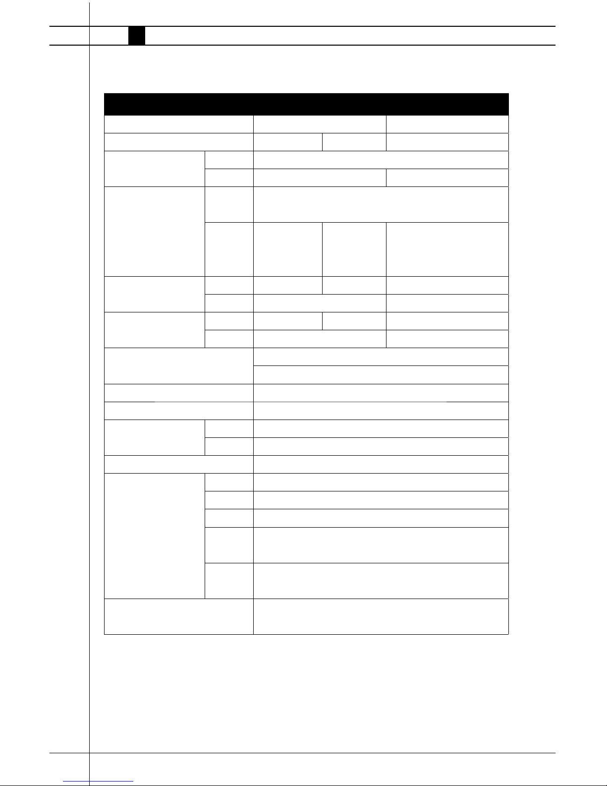
Specifications
Description Model
TS350DF TS350
Fuel Type Propane Gas Natural Gas Propane Gas
Maximum Input (Btuh/kW) MAX 350,000 / 102.6
MIN N/A 175,000 / 51.3
Inlet Gas Supply Pressure
Acceptable at the Inlet of
the Heater for Purpose of
INput Adjustment (Inches
W.C./kPa)
MAX 13.5 / 3.36
MIN 11.0 / 2.74 7.0 / 1.74 11.0 / 2.74
Burner Manifold Pressure
(Inches W.C/kPa)
MAX 5.2 / 1.30 5.3 / 1.32 8.0 / 2.0
MIN N/A 2.0 / .49
Fuel Consumption Per
Hour
MAX 16.2 lbs. / 7.34 kg 350 cu.ft./9.9m³ 16.2 lbs./7.34 kg
MIN N/A 8.12 lbs/3.54 kg
Motor Characteristics Ball Bearing
1 H.P. / 745.7 Watts / 1,725 RPM
Blower Speed 915 RPM
Electrical Supply (Volts/Hz/Phase) 115 / 60 / 1
Amp Draw Starting 35.0
Continuous 11.0
Dimensions L x W x H (Inches/cm) 48 x 22.25 x 32.75 / 122 x 56.5 x 83.2
Minimum Safe Distances
from Nearest Combustible
Material (Feet / Meters)
Top 1 / 0.3
Sides 1 / 0.3
Back 1 / 0.3
Blower
Outlet
6 /1.83
Gas
Supply
Propane - U.S.: 6, Canada: 3.05 - Natural Gas - N/A
Minimum Ambient Temperature
Can be Used
-20°F / -29°C

Premier Ductable Heaters
Owner’s Manual • Premier 350
5
This Owner’s Manual includes accessories commonly
used on this heater. These accessories must be
ordered seperately.
When calling for technical service assistance, or for
other specifi c information, always have model
number, confi guration number and serial number
available. This information is contained on the
dataplate.
This manual will instruct you in the operation and care
of your unit. Have your installer review this manual
with you so that you fully understand the heater and
how it functions.
Contact your local L.B. White distributor or the
L.B. White Co., Inc. for assistance, or if you have
any questions about the use of the equipment or its
application.
The L.B. White Co., Inc. has a policy of continuous
product improvement. It reserves the right to change
specifi cations and design without notice.
General Information
Premier Ductable Heaters
www.lbwhite.com
Owner’s Manual • Premier 350
6
Propane gas and natural gas have man-made odorants added specifi cally for detection of fuel gas leaks.
If a gas leak occurs, you should be able to smell
the fuel gas . THAT’S YOUR SIGNAL TO GO INTO
IMMEDIATE ACTION!
■ Do not take any action that could ignite the fuel
gas. Do not operate any electrical switches. Do not
pull any power supply or extension cords. Do not
light matches or any other source of fl ame. Do not
use your telephone.
■ Get everyone out of the building and away from the
area immediately.
■ Close all fuel supply valves.
■ Propane gas is heavier than air and may settle in
low areas. When you have reason to suspect a
propane leak, keep out of all low areas.
■ Use your neighbor’s phone and call your fuel gassupplier and your fi re department. Do not re-enter
the building or area.
■ Stay out of the building and away from the area
until declared safe by the fi refi ghters and your fuel
gas supplier.
■ FINALLY, let the fuel gas service person and the
fi refi ghters check for escaped gas. Have them
air out the building and area before you return.
Properly trained service people must repair the
leak, check for further leakages, and then relight
the heater for you.
■ Some people cannot smell well. Some people
cannot smell the odor of the man-made chemical added to propane or natural gas. You must
determine if you can smell the odorant in these
fuel gases.
■ Learn to recognize the odor of propane gas and
natural gas. Local propane gas dealers and your
local natural gas supplier (utility) will be more than
happy to give you a “scratch and sniff” pamphlet.
Use it to become familiar with the fuel gas odor.
■ Smoking can decrease your ability to smell. Being
around an odor for a period of time can affect your
sensitivity to that particular odor.
■ The odorant in propane gas and natural gas is colorless and the intensity of its odor can fade under
some circumstances.
■ If there is an underground leak, the movement of
gas through the soil can fi lter the odorant.
■ Propane gas odor may differ in intensity at different
levels. Since propane gas is heavier than air, there
may be more odor at lower levels.
■ Always be sensitive to the slightest gas odor. If you
continue to detect any gas odor, no matter how
small, treat it as a serious leak. Immediately go into
action as discussed previously.
Fuel Gas Odor
Safety Precautions
Odor Fading - No
Odor Detected
WARNING
Asphyxiation Hazard
■ Do not use this heater for heating human living quarters, garages, workshops, or other such
confi ned spaces.
■ Do not use in unventilated areas.
■ The fl ow of combustion and ventilation air must not be obstructed.
■ Proper ventilation air must be provided to support the combustion air requirements of the heater
being used.
■ Lack of proper ventilation air will lead to improper combustion.
■ Improper combustion can lead to carbon monoxide poisoning leading to serious injury or death.
Symptoms of carbon monoxide poisoning can include headaches, dizziness and diffi culty in
breathing.
■ Proper ventilation air for combustion must be provided in accordance with OSHA 29 CFR
1926.154, Temporary Heating Devices, ANSI A10.10, Safety Requirements for Temporary and
Portable Space Heating Devices, or the Natural Gas and Propane Installation Code, CAN/CSA
B149.1 as appropriate.

Premier Ductable Heaters
Owner’s Manual • Premier 350
7
2. All installations and applications of L.B. White
heaters must meet all relevant local, state and
national codes. Included are L.P. gas, natural gas,
electrical, and safety codes. Your local fuel gas
supplier, a local licensed electrician, the local fi re
department or similar government agencies, or
your insurance agent can help you determine code
requirements.
Refer to the following:
U.S. Installations:
-- ANSI/NFPA 58, latest edition, Standard for Storage
and Handling of Liquefi ed Petroleum Gas and/or
-- ANSI Z223.1/NFPA 54, National Fuel Gas Code
-- ANSI/NFPA 70, National Electrical Code.
Canadian Installations:
-- CSA B149.1 Natural Gas and Propane Gas Instal-
lation Code.
-- CSA C22.1 Part 1 Standard Canadian Electrical
Code, and CSA C22.2 No.3, Electrical Features of
Fuel Burning Equipment.
3. We cannot anticipate every use which maybe
made of our heaters. Other standards govern the
use of fuel gases and heat producing products
in specifi c applications. Your local authority can
advise you about these. Check with the local
fi re safety authority if you have questions about
applications.
4. Do not wash the interior of the heater. Use only
compressed air, a soft brush or dry cloth to clean
the interior of the heater and it’s components.
5. For safety, this heater is equipped with manual
reset high limit switches, an air-proving switch
and a redundant gas control valve. Never operate
the heater with any safety device that has been
bypassed. Do not operate this heater unless all of
these features are fully functioning.
6. Do not locate fuel gas containers or fuel supply
hoses within 20 ft./6.10 meters of the blower outlet
of the heater.
7. Do not block air intakes or discharge outlets of the
heater. Doing so may cause improper combustion or damage to heater components leading to
property damage.
■ Propane gas has a distinctive odor. Learn to
recognize these odors. (Reference Fuel Gas Odor
and Odor Fading sections above).
■ If you have not been properly trained in repair and
service
■ Even if you are not properly trained in the service
and repair of the heater, ALWAYS be consciously
aware of the odors of propane gas and natural gas.
A periodic sniff test around the heater or at the
heater’s joints; i.e. hose, connections, etc., is a good
safety practice under any conditions. If you smell
even a small amount of gas, CONTACT YOUR FUEL
GAS SUPPLIER IMMEDIATELY. DO NOT WAIT!
1. Do not attempt to install, repair, or service this
heater or the gas supply line unless you have
continuing expert training and knowledge of gas
heaters.
QUALIFICATIONS FOR SERVICING AND
INSTALLATION:
a. To be a qualifi ed gas heater service person, you
must have suffi cient training and experience to
handle all aspects of gas-fi red heater installation,
service and repair. This includes the task of installation, troubleshooting, replacement of defective
parts and testing of the heater. You must be able
to place the heater into a continuing safe and
normal operating condition. You must completely
familiarize yourself with each model heater by
reading and complying with the safety instructions,
labels, Owner’s Manual, etc., that is provided with
each heater.
b. To be a qualifi ed gas installation person, you must
have suffi cient training and experience to handle
all aspects of installing, repairing and altering gas
lines, including selecting and installing the proper
equipment, and selecting proper pipe and tank size
to be used. This must be done in accordance with
all local, state and national codes as well as the
manufacturer’s requirements.
c. In the Commonwealth of Massachusetts, this
product must be installed by a gas fi tter licensed in
the Commonwealth of Massachusetts.
Attention - Critical
Points to Remember!

Premier Ductable Heaters
www.lbwhite.com
Owner’s Manual • Premier 350
8
8. The hose assembly shall be visually inspected on
a daily basis after heater relocation and when the
heater is in use. If it is evident there is excessive
abrasion or wear, or if the hose is cut, it must be
replaced prior to the heater being put into operation. The hose assembly shall be protected from
building materials, and contact with hot surfaces
during use. The replacement hose assembly
shall be that specifi ed by the manufacturer. See
parts list.
9. Premier 350DF heaters are equipped with a gas
selector valve. The selector valve must be properly positioned for the gas supplied to the heater.
Further information on this feature is provided on
page 17 of this manual.
10. Check for gas leaks and proper function upon
heater installation, when relocating, and after
servicing. Refer to leak check instructions within
installation section of this manual.
11. This heater shall be inspected for proper opera-
tion by a qualifi ed service person before each
use and at least annually.
12. Always turn off the gas supply to the heater if the
heater is not going to be used in the heating of
the work space.
13. This heater is equipped with a three-prong
(grounding) plug for your protection against
shock hazard and must be plugged directly into
a properly grounded three-prong receptacle.
Failure to use a properly grounded receptacle
can result in electrical shock, personal injury, or
death.
14. If gas fl ow is interrupted and fl ame goes out, do
not relight the heater until you are sure that all
gas that may have accummulated has cleared
away. In any event, do not relight the heater for
at least 5 minutes.
15. The heater requires a minimum 500 gallon/1892
litre propane tank for proper gas supply pressure
and operation. A larger tank may be required
depending upon operating conditions at the site.
16. When the heater is to be stored indoors, the
connection between the propane gas supply
cylinder(s) and the heater must be disconnected
and the cylinder(s) removed form the heater and
stored in accordance with the Standard for the
Storage and Handling of Liquifi ed Petroleum
Gases, ANSI/NFPA 58 or Standard CSA B149.1
Natural Gas and Propane Installation Code as
appropriate.
17. Propane gas supply containers have left handed
threads. Always use the appropriate wrench
to make a connection to tighten or loosen the
pigtail connector’s P.O.L. fi tting at the container’s
gas supply valve.
Premier Ductable Heaters
Owner’s Manual • Premier 350
9
building materials (tar, concrete, plaster, etc.)
which can affect safe operation and could result
in property damage or injury.
5. Heaters used in the vicinity of combustible
tarpaulins, canvas, plastics, wind barriers,
or similar coverings shall be located at least
10 ft./3.05 meters from the coverings. The
coverings shall be securely fastened to prevent
ignition or upsetting of the heater due to wind
action on the covering or other material.
6. Check all connections for gas leaks using approved gas leak detectors. Gas leak testing is
performed as follows:
-- Check all pipe connections, hose connections,
fi ttings and adapters upstream of the gas control
with approved gas leak detectors.
-- In the event a gas leak is detected, check the
components involved for cleanliness and proper
application of pipe compound before further
tightening.
-- Furthermore, tighten the gas connections as
necessary to stop the leak.
-- After all connections are checked and any leaks
are stopped, turn on the main burner.
-- Stand clear while the main burner ignites to
prevent injury caused from hidden leaks that
could cause fl ashback.
-- With the main burner in operation, check all
connections, hose connections, fi ttings and joints
as well as the gas control valve inlet and outlet
connections with approved gas leak detectors.
General Installation Instructions
WARNING
Burn Hazard
Can cause property damage, severe injury or death.
1. To avoid dangerous accumulation of fuel gas, turn
off gas supply at the appliance service valve before
starting installation, and perform gas leak test after
completion of installation.
2. Do not force the gas control knob. Use only your
hand to turn the gas control knob. Never use any
tools. If the knob will not operate by hand, the
control should be replaced by a qualifi ed service
technician. Force or attempted repair may result in
fi re or explosion.
1. Read all safety precautions and follow L. B. White
recommendations when installing this heater. If
during the installation or relocating of heater, you
suspect that a part is damaged or defective, call a
qualifi ed service agency for repair or replacement.
2. Make sure the heater is level (use a level) and
properly positioned before use. Observe and obey
all minimum safe distances of the heater to the
nearest combustible materials. Safe distances are
given on the heater dataplate and on page 4 of this
manual.
3. This heater may be installed either indoors or outdoors. For outdoor installations, only the following
air distribution devices may be used:
-- 18 in./43.7 cm Dia. x 12 ft./3.66 m Duct: Part
#22835
-- End Diffuser: Part #23189
DO NOT USE ANY OTHER LENGTH OF DUCTWORK OR FIELD FABRICATED DUCT, TARPS,
STOVE PIPE, ETC. ON THIS HEATER.
■ When using the ducting, ensure that bends in duct
are kept to a minimum. A maximum of two 90º
bends is allowed.
■ Reducing the number of bends will ensure that the
warm air exiting the heater fl ows freely, thereby
preventing overheating. If there are excessive
bends, the high limit switches may open.
4. The heater’s gas pressure regulator (with pressure
relief valve) must be protected from adverse
weather conditions (rain, ice, snow) as well as from
WARNING
Fire and Explosion Hazard
■ Do not use open fl ame (matches, torches,
candles, etc.) in checking for gas leaks.
■ Use only approved leak detectors.
■ Failure to follow this warning can lead to fi res
or explosions.
■ Fires or explosions can lead to property damage, personal injury or loss of life.

Premier Ductable Heaters
www.lbwhite.com
Owner’s Manual • Premier 350
10
-- If a leak is detected, check the components
involved for cleanliness in the thread areas and
proper application of pipe compound before
further tightening.
-- Tighten the gas connection as necessary to stop
the leak.
-- If necessary, replace the parts or components
involved if the leak cannot be stopped.
-- Ensure all gas leaks have been identifi ed and
repaired before proceeding.
7. A qualifi ed service agency must check for proper
operating gas pressure upon installation of the
heater.
8. Light according to instructions on heater or within
owner’s manual.
9. Make sure the heater has the proper gas
regulator for the application. A regulator must be
connected to the gas supply so that gas pressure
at the inlet to the gas valve is regulated within the
range specifi ed on the dataplate at all times.
Premier 350DF heaters: The regulator supplied with the heater is suitable for use with propane
gas or natural gas.
Premier 350 Propane Gas heaters: The
regulator supplied with these heaters is designed for
use specifi cally for the fuel being used.
Contact your gas supplier, or the L.B. White Co., Inc.
if you have any questions.
10. This heater is confi gured for use for L.P. gas va-
por withdrawal. Do not use the heater in an L.P.
gas liquid withdrawal system or application. If
you are in doubt, contact the L.B. White Co., Inc.
11. The heater must be installed so as not to inter-
fere with or obstruct normal exits, emergency
exits, doors and walkways.
12. Railing, fencing or suitable substitute materials
must be used to keep the heating equipment
from any people using and visiting the structure.
13. The heater shall be located so that rain, ice, or
snow drainage from the structure does not affect
equipment operation. If the heater is mounted
outside, it must be mounted above any pooled or
standing water. If the unit is to be located on
the ground, a surrounding trench is recommended to drain any rain, ice or snow away
from the unit.
14. The ground and surrounding terrain must be
cleared of any combustible vegetation and
other combustible materials when the heater
is utilized outside.
15. Eventually, like all electrical/mechanical
devices, the thermostat can fail. Thermostat failure may result in an underheating
condition. The thermostat should be tested
to make sure it turns the heater on and off
within a temperature differential of ±3°F
(±1.5 °C).
16. Take time to understand how to operate and
maintain the heater by using this Owner’s
Manual. Make sure you know how to shut
off the gas supply to the building and also to
the individual heater. Contact your fuel gas
supplier if you have any questions.
17. Any defects found in performing any of the
service or maintenance procedures must
be eliminated and defective parts replaced
immediately. The heater must be retested by
properly qualifi ed service personnel before
placing the heater back into use.
Premier Ductable Heaters
Owner’s Manual • Premier 350
11
The vaporization of propane is affected by several
factors: the surface area of the container, the liquid
level of propane, temperature surrounding the
container, and the relative humidity. All of these
factors are specifi c to a site. Therefore, a degree of
experience and judgement is required to select the
proper propane supply.
Although experience is the best guide, the following recommendations can be used as a starting
point. The table is based on experience in northern
climates where cold weather and high humidity are
prevalent in the winter. If more or less favorable
conditions prevail at a specifi c site, adjustments can
be made on the basis of experience.
If more than one gas supply container is used per
heater, the containers must be manifolded together
to allow vapor withdrawal simultaneously from
multiple containers. Manifold system shall be in accordance with NFPA 58 or CSA B149.1.
Gas Supply Sizing
Recommended Gas Supply
TANK SIZE HEATERS / TANK
500 gall. / 1892 litre 1
1000 gall. / 3784 litre 2
Premier Ductable Heaters
www.lbwhite.com
Owner’s Manual • Premier 350
12
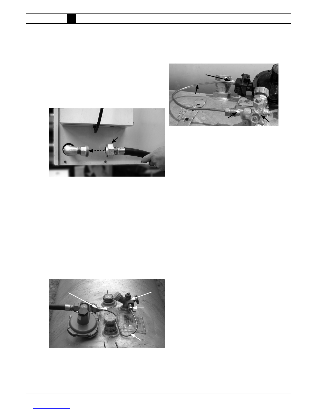
1. Thread swivel onto connector at gas inlet of heater.
See Fig. 1. Tighten securely.
2. The hose may be coiled up and hung on the hose
hanger, with the regulator stored within the regulator
storage bracket.
FIG. 1
Connecting Regulator to
Gas Supply
WHEN USING PROPANE GAS:
1. Lift the tank’s cover.
2. Assemble the gas componets as shown, depending
on heater type. Tighten connections securely. See
Fig. 2 for Premier 350DF heaters, and Fig. 3 for
Standard Premier 350 LP heaters.
FIG. 2
Connecting Hose to
Heater
SWIVEL
PREMIER 350 DUAL FUEL CONNECTIONS
3/4 X 1/4 Bushing Tank Valve
POL
Pigtail Connector
1/4 in.
NPT
FIG. 3
3. Form the connector to ensure the regulator will be
supported by the tank, and the tank valve cover will
protect the regulator from weather conditions.
4. Thread connector’s POL fi tting counter-clockwise
into the tank valve. Tighten securely. See Fig. 2 or
Fig. 3.
5. Open the tank valve.
6. Check all connections with an approved leak detector. Close the tank’s cover.
7. When storing or transporting the heater, ensure the
connector’s fi tting is protected from damage and
dirt entry.
WHEN USING NATURAL GAS:
--- The regulator only should be used if the gas supply
pressure to the heater is above the maximum inlet
pressure stated on the heater’s dataplate.
--- Connect the regulator as supplied with the heater
to the natural gas supply line, using the appropriate connections. (DO NOT USE THE POL/PIGTAIL
FOR NATURAL GAS INSTALLATIONS)
--- Gas supply pressure to the regulator
must be a minimum of 2 PSI/13.7 kPa.
--- The regulator supplied with Premier
350 DF heater is also for use with
natural gas.
STANDARD PREMIER 350 LP CONNECTIONS
1/4 In. NPT
Pigtail Connector
POL Fitting
Tank Valve

Premier Ductable Heaters
Owner’s Manual • Premier 350
13
Thermostat
The remote thermostat that ships with this heater is
factory wired into the control circuit.
Premier 350 DF heaters:
The thermostat is a single stage design. When
there is a call for heat from the thermostat, the
thermostat cycles the heater to full heat output.
Premier 350 Propane Gas heaters:
The thermostat is a two stage device and is
designed to cover a broad range of heating
requirements.
The two stage thermostat allows the heater to fi ll
an application where a single high heat rate is
undesirable. The two stage thermostat will allow the
heater to operate and cycle at a low heat condition
when the heating load is less severe, or it will cycle
to highest heat as demand is increased.
Premier Ductable Heaters
www.lbwhite.com
Owner’s Manual • Premier 350
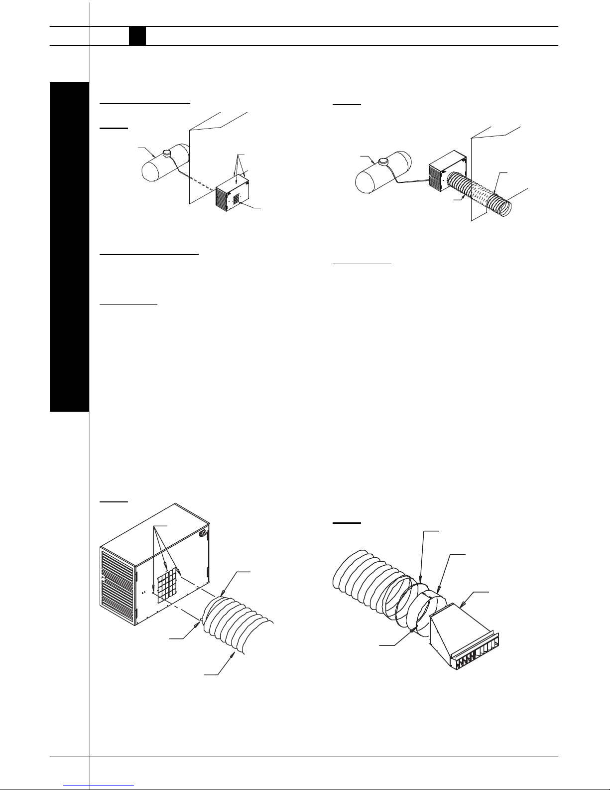
14
CLAMP
DUCT ADAPTER
TABS
DIFFUSER
Installation of Heater
Inside of Structure
FIG. 4
Outside of Structure
(Air distribution accessories not supplied with heater)
A. Flex Duct Kit
Part Number: 22835 (18 in. x 12 ft. / 46 cm x 3.65 m)
1. Extend duct kit to 12 feet/3.6 meter length.
2. Mount duct to blower outlet of heater by inserting tabs
on duct adapter into vertical and horizontal slots located
at top and sides of blower outlet. See Fig. 5. Push down
on duct adapter to secure adapter into slots. See below
for typical installation of heater located at exterior.
When using 12 ft. / 3.65m fl ex ducts, the maximum
number of fl ex ducts to use per heater is 3. See Fig. 6
for typical installation.
FIG. 5
SLOTS
DUCT ADAPTER
WITH TABS
TA B
DUCT KIT
SIDE WALL
500 GALLON (1892 litre)
GAS SUPPLY
(MINIMUM)
MINIMUM SAFE DISTANCE FROM
GAS SUPOPLY TO HEATER MUST
CONFORM TO LOCAL CODES
DISTANCE FROM HEATER TO SIDE WALL MUST
COMPLY WITH LOCAL CODES, AND BE ACCORDING
TO MANUFACTURER'S REQUIREMENTS
MINIMUM SAFE DISTANCE FROM
BLOWER OUTLET TO COMBUSTIBLES
IS 6 FEET (1.83m)
MINIMUM SAFE DISTANCE FROM
TOP, SIDES, AND BACK OF HEATER
TO COMBUSTIBLES IS 1 FOOT (0.3m)
INSTALLATION INSTRUCTIONS
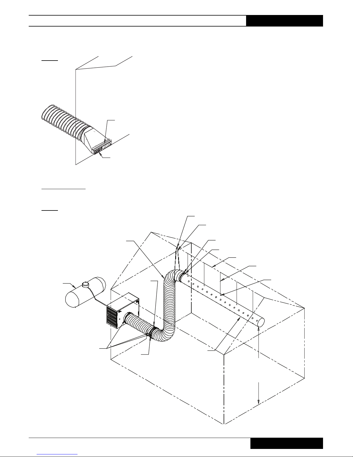
FIG. 6
MINIMUM SAFE DISTANCE FROM GAS
SUPPLY TO HEATER MUST CONFORM
TO LOCAL CODES
DISTANCE FROM HEATER TO SIDE WALL MUST
COMPLY WITH LOCAL CODES, AND BE ACCORDING
TO MANUFACTURER'S REQUIREMENTS
TENT DRAPED OVER DUCT
DUCT KIT
500 GALLON
(1892 LITRE)
GAS SUPPLY
(MINIMUM)
SIDE WALL
TENT DRAPED
OVER DUCT
B. End Diffuser
Part Number: 23189
1. Loosen screw on duct clamp so clamp is easily
positioned over ribs at end of fl exible duct.
2. Slide duct adapter into duct end. Duct adapter tabs
must be facing away from duct and are located at 3,
9 and 12 o’clock positions. See Fig. 7.
3. Tighten screw clamp so adapter is held securelywithin duct.
4. Insert tabs of adapter into slots on air diffuser back.
5. Push down on adapter so tabs are seated fi rmly to
air diffuser.
6. Locate diffuser under side wall. See Fig. 8.
FIG. 7
Premier Ductable Heaters
Owner’s Manual • Premier 350
15
TENT DRAPED OVER DIFFUSER
TENT SIDE WALL
TENT DRAPED
WITHIN DIFFUSER
CHANNEL
OPTIONAL AIR DIFFUSER
FIG. 8
C. Infl atable Ducting
Use only 2 fl ex ducts when also using infl atable duct.
FIG. 9
500 GALLON
(1892 LITRE)
GAS SUPPLY
(MINIMUM)
TO ALLOW PROPER AIR DISTRIBUTION
FLEXT DUCT MUST NOT HAVE MORE THAN
TWO 90 DEGREE BENDS
CLEARANCE OF HEATER TO
TENT WALL MUST CONFORM
TO LOCAL CODES
CLAMP
MATERIAL
DRAPED
OVER DUCT
DUCT RING
INFLATABLE DUCT,
100 FT. (130.5m)
DISCHARGE HOLES
POINTED DOWNWARD
(OPTIONAL ACCY 23053)
8 FEET (12.44m)
CLEARANCE
TO GROUND
TYPICAL
CHAIN LOOPED AROUND DUCT
DUCT RING
ROOF SUPPORT
WIRE OR CABLE
(SUPPLIED BY CUSTOMER)
HANGING CLAMP
S-HOOK
CLAMP
Premier Ductable Heaters
www.lbwhite.com
Owner’s Manual • Premier 350
16
Start-Up Instructions
For initial start-up after heater installation, follow
steps 1-5. For normal start-up, set the thermostat
above room temperature.
1. Connect electrical cord to an approved electrical
outlet.
2. Set thermostat to desired room temperature.
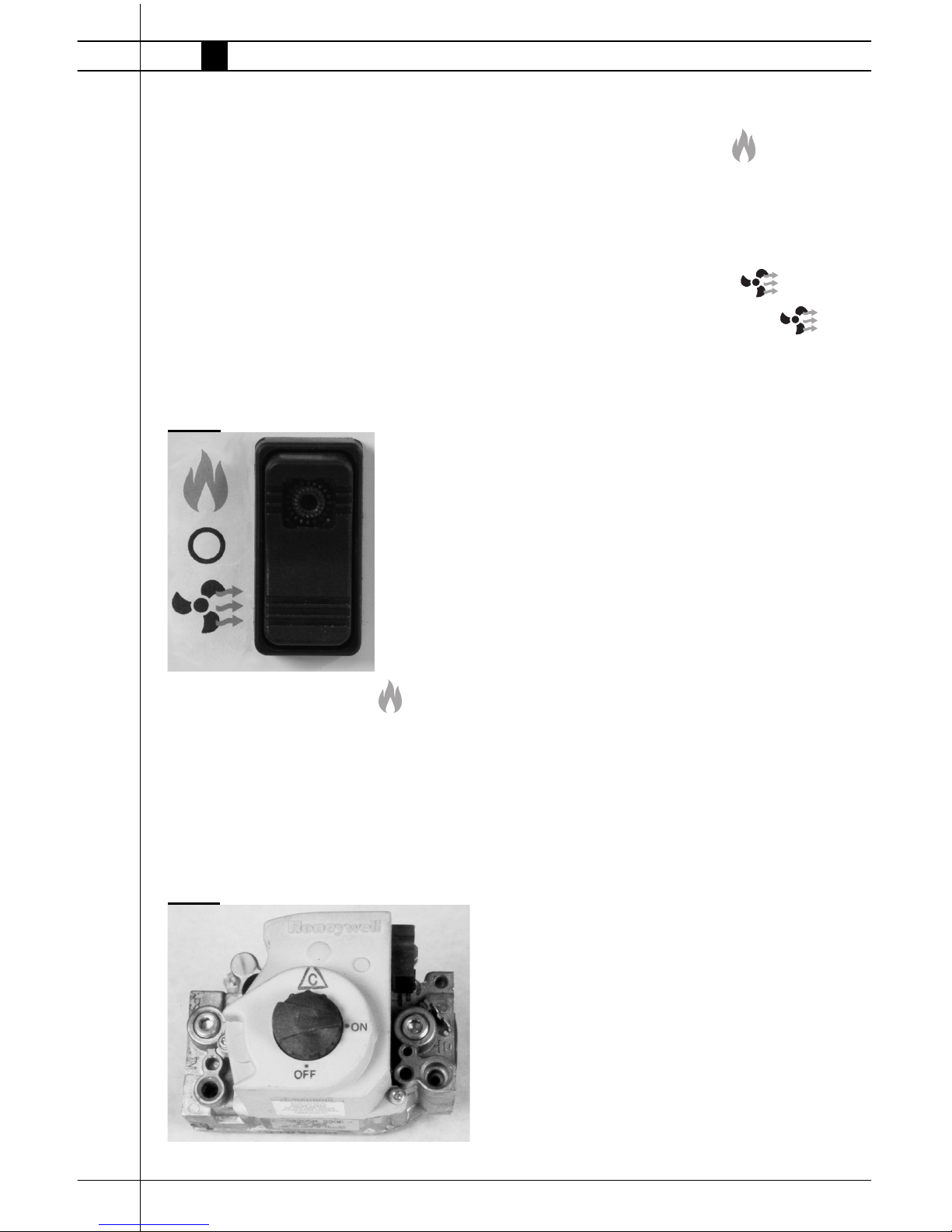
3. A selector switch is located on the back of the
heater. This switch allows you to either heat or
ventilate (no heat). See Fig. 10 for selector switch
positions.
FIG. 10
A. Heating Mode Operation
a. Open all manual fuel supply valves. Check for
gas leaks using an approved leak detector.
Regardless of model purchased , the gas control
valve in the heater has a manual shut-off feature
incorporated into the valve assembly. Ensure the
indicator is turned to the on position. See Fig 11,
Premier 35DF valve shown.
FIG. 11
b. Position the selector switch to heat.
See Fig. 10. A red light within the switch will come
on. The fan motor will start, the igniter will spark
and ignition will occur. The thermostat will cycle
the heater on or off based upon temperature
setting.
B. Ventilation Mode Operation
When the selector switch is positioned to vent,
the red light will NOT be on. The fan motor will start,
but the igniter will not spark, nor will ignition occur.
This feature is used only when air circulation is
required. The heater will not cycle on its thermostat
setting. To discontinue the ventilation feature, position the switch to off or heat.
C. Off O
Position the switch to midpoint. O
ATTENTION
■ It is normal for air to be trapped in gas hose on
new installations. The heater may attempt more
than one trial for ignition before air is fi nally
purged from line and ignition takes place.
4. The direct spark ignition (DSI) control board
within this heater is self-diagnostic. The board
works in conjunction with a light emitting diode
(L.E.D.) built into the selector switch. The L.E.D.
will fl ash a specifi c continuous fl ash pattern de-
pending on a problem that occurs. Match specifi c
fl ash pattern given by L.E.D. to troubleshooting
label applied to inside of burner cap access panel
of the heater. The troubleshooting label identifi es the causes of the problem as it relates to
specifi c fl ash pattern and remedies to correct the
problem. See also “Troubleshooting Data” within
this Owner’s Manual.
5. Gas Control Valve
Premier 350 DF Heaters:
The gas control is a single stage design. When the
valve opens, it delivers full heat output.
Premier 350 Propane
Gas Heaters:
The gas control valve is a step opening design.
When a call for heat occurs, the valve will open to
a rate equal to half its total heat output. Depend-
Premier Ductable Heaters
Owner’s Manual • Premier 350
17
ing upon temperature requirements and thermostat
setting, the valve will then either remain at low heat rate
before the thermostat is satisfi ed, or the valve will open
completely to its total capacity.
5. Do not exceed input rating stamped on nameplate or
manufacturer’s recommended burner orifi ce pressure
for size orifi ce(s) used. Make certain that the primary
air supply to main burner is open and free of dust, dirt
and debris for complete, proper combustion.
Shut-Down Instructions
If the heater is to be shut down for cleaning, maintenance, or repair, follow steps 1-5. Otherwise, set the
thermostat to below room temperature for standard
shut-down. Do not shut the heater off by
the selector switch. Doing so will remove
power to the heater, preventing cooling of
heat chamber. The burner end high limit
switch will trip.
1. Close the gas supply valve.
2. Allow the heater to burn off any fuel gas remaining in
the gas supply line.
3. Set the thermostat below room temperature. When
the thermostat cycles the burner off, the
fan motor will continue to run for 1 minute, allowing the heat chamber to cool.
After 1 minute, the fan motor will shut off.
4. Position selector switch to off O
5. Disconnect the heater from its gas and electrical
supplies.
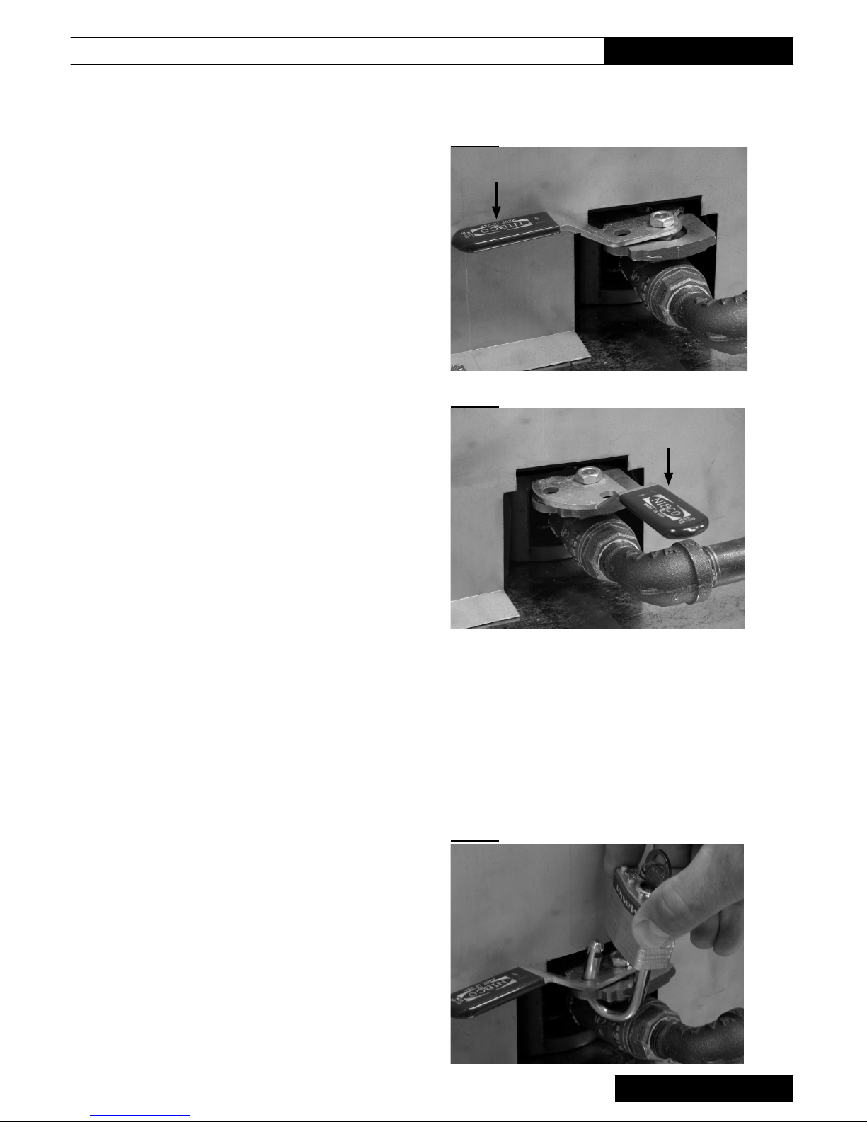
Gas Selector Valve
Premier 350 DF Only
1. This feature allows the heater to operate on either pro-
pane or natural gas without changing out the burner
orifi ce. The gas selector valve is located between
the gas control valve and the burner. Gas selection
is made by repositioning the valve’s handle. THIS IS
NOT A MANUAL GAS SHUT OFF VALVE.
2. Refer to Figs. 12 and 13. The valve handle must be
properly positioned for the specifi c gas being used,
otherwise the unit will overheat or underheat.
FIG. 12
FIG. 13
3. The handle must be fully set at 90 degrees to gas
fl ow (propane gas) or parallel to gas fl ow (natural
gas) for proper operation. Do not operate the
heater with the valve handle set between either
postion, otherwise improper operation will occur.
4. The valve’s handle can be locked to prevent
improper positioning. Use the holes provided on
the valve’s body and handle. See Fig. 14.
FIG. 14
Handle position
propane gas
Handle position
natural gas
Premier Ductable Heaters
www.lbwhite.com
Owner’s Manual • Premier 350
18
Cleaning Instructions
WARNING
Fire, Burn, and Explosion Hazard
■ This heater contains electrical and mechanical
components in the gas management, safety
and airfl ow systems.
■ Such components may become inoperative or
fail due to dust, dirt, wear, aging, or the corrosive atmosphere of an animal confi nement
building.
■ Periodic cleaning and inspection as well as
proper maintenance are essential to avoid
serious injury or property damage.
1. Before cleaning, shut off all gas supply valves
and disconnect the electrical supply.
2. The heater should have dirt or dust removed
periodically:
a. Before each use give the heater a general
cleaning using compressed air or a soft
brush or dry rag on its case and internal
components. At this time, dust off the motor
case to prevent the motor from over-heating.
b. At least once a year, give the heater a thor-
ough cleaning. At this time, remove the fan
and motor assembly and brush or blow off
the fan blade assembly. Additionally, make
sure the burner air inlet venturi ports and
the casting are free of dust accumulation.
WARNING
Do not use a pressure washer, water, or liquid
cleaning solution on any gas controls. Use of a
pressure washer, water, or liquid cleaning solution on the control components can cause severe
personal injury or property damage due to water
and/or liquids:
■ In electrical components, and wires causing
electrical shock or equipment failure.
■ On gas control valves causing corrosion which
can result in gas leaks and fi re or explosion
from the leak.
Clean all components of the heater with
pressurized air, a dry brush, or a dry cloth.

Premier Ductable Heaters
Owner’s Manual • Premier 350
19
Maintenance Instructions
BEFORE EACH USE:
■ Check the area surrounding the heater to
ensure it is clear and free of combustible materials, gasoline, and other fl ammable vapors
and liquids.
■ Have your gas supplier check all gas connections for leaks or restrictions in gas lines.
■ Inspect the regulator vent to make sure the
regulator vent is not blocked. Debris, insects,
insect nests, snow, or ice on a regulator can
block vents and cause excess pressure at the
heater.
■ Check all wiring associated terminals and electrical components within the heater for corrosion, frayed or cut insulation, tight connections,
etc. Repair or replace as necessary.
■ Check the hose assembly after heater
installation, relocation and when the heater
is in use. If it is evident there is excessive
abrasion or wear, or if the hose is cut, it must
be replaced prior to the heater being put back
into operation
■ Check the heater’s fan drive belt. Make sure
the belt is not cracked. If so, replace it. Additionally, ensure the belt is not slipping, that belt
tension is proper, and sheaves are properly
aligned and not worn.
■ Review all heater markings (i.e. wiring diagram, warnings, start-up, shut-down, troubleshooting, etc.) at the time of maintenance
for legibility. Make sure none are cut, torn, or
otherwise damaged. Any damaged markings
must be replaced immediately by contacting
the L.B. White Co., Inc. Data plate, startup
and shut-down instructions and warnings are
available at no cost.
MONTHLY
■ Lubricate the bearings once a month. Use
NLGI grade 2 mineral oil lithium or lithium base
grease.
ANNUALLY:
■ Clean and check the igniter for cracks. Replace
if necessary.
■ Regulators can wear out and function improperly.
Have your gas supplier check the date codes
on all regulators installed and check delivery
pressures to the heater to make sure that the
regulator is reliable.
■ Test both manual reset high limit heat switches
to ensure proper operation. (See Testing instructions for same in this owner’s manual.)
Premier Ductable Heaters
www.lbwhite.com
Owner’s Manual • Premier 350
20
Service Instructions
1. Close the fuel supply valve to the heater and
disconnect the electrical supply before servicing
unless necessary for your service procedure.
2. Clean the heater’s orifi ce with compressed air or
a soft, dry rag. Do not use fi les, drills, broaches,
etc. to clean the orifi ce hole. Doing so will enlarge
the hole, causing combustion or ignition problems.
Replace the orifi ce if it cannot be cleaned properly.
3. The high limit switches, heat/vent switch and thermostat can be tested by disconnecting the leads at
the component and jumpering the leads together.
-- Reconnect the electrical supply and open fuel
supply valves.
-- If the heater lights, the component is defective and
must be replaced.
-- Do not leave the jumper on or operate the heater if
the part is defective. Replace the part immediately.
-- An alternate method for checking the components
is to perform a continuity check..
4. The air proving switch must not be jumpered. If
jumpered, the ignition control will not allow heater
operation. Test the air proving switch for continuity.
If defective, replace the switch
WARNING
Burn Hazard
■ Heater surfaces are hot for a period of time after
the heater has been shut down.
■ Allow the heater to cool before performing
service, maintenance, or cleaning.
■ Failure to follow this warning will result in burns
causing injury.
WARNING
Fire and Explosion Hazard
■ Do not disassemble or attempt to repair any
heater components or gas train components
such as gas valves, or gas hoses.
■ All component parts must be replaced if defects
are found.
■ Failure to follow this warning will result in fi re or
explosions, causing property damage, injury, or
death.
5. Open the respective case panel for access to
burner or fan related components.
6. For reassembly, reverse the respective service
procedure. Ensure gas connections are tightened
securely.
7. After servicing, start the heater to ensure proper
operation and check for gas leaks.
8. If pulley or fan keys are lost during service, replacements are made by using 3/16 in. (4.7 mm.)
square x 1 in. (2.54 cm) bar stock. Otherwise,
order Part #22955.
Belt Replacement
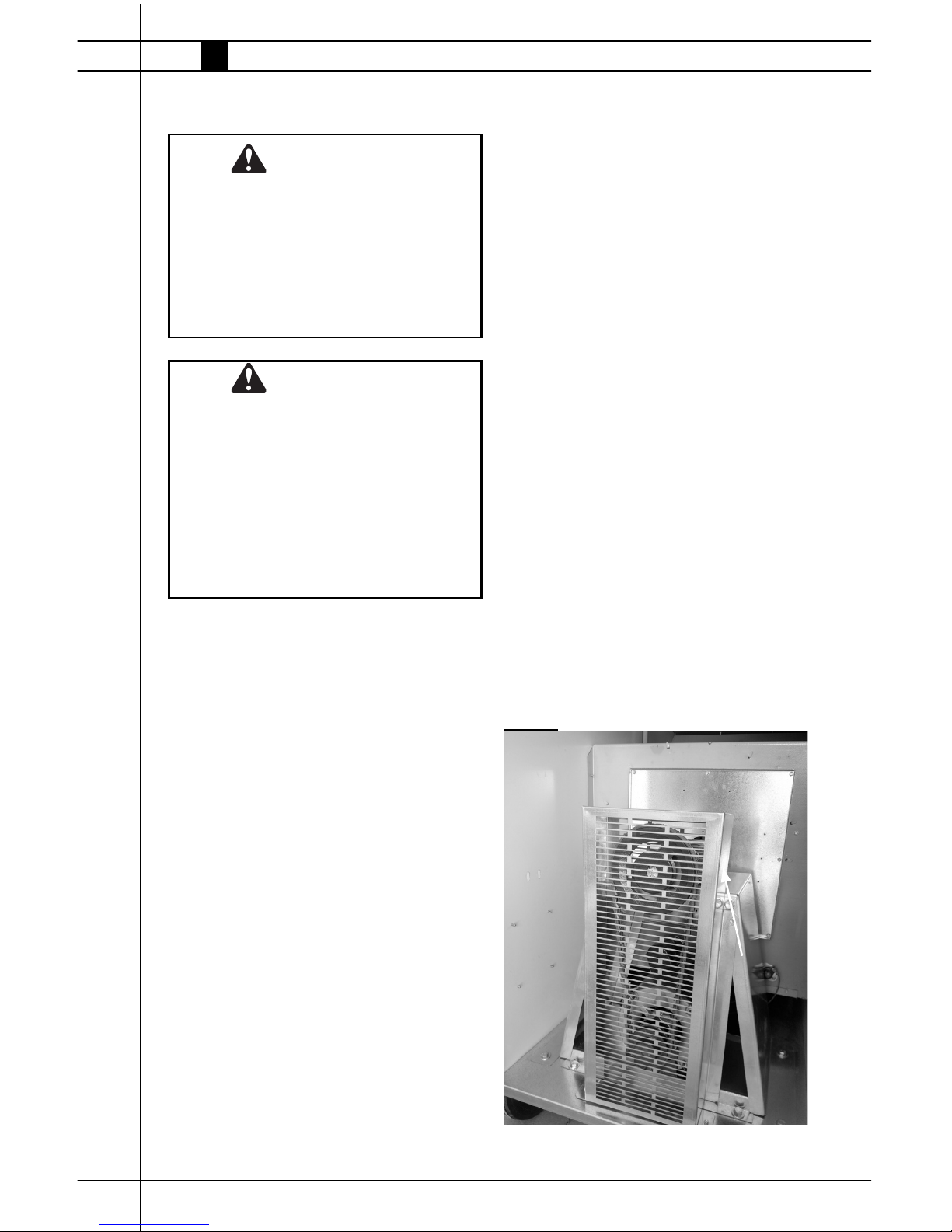
1. Remove the belt guard from the heater.
See Fig. 15.
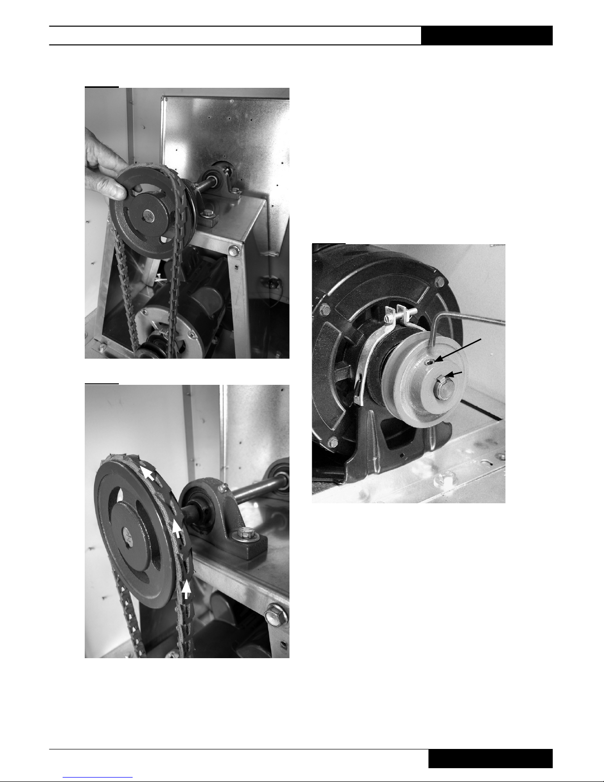
2. Rotate the fan pulley CW while carefully lifting the
belt so it clears the fan pulley groove. See Fig.16.
3. Check the fan and motor pulleys for dirt. Clean
the pulleys if needed.
4. When reinstalling the belt, ensure the arrows are
directed CCW. See Fig. 17.
FIG. 15
Premier Ductable Heaters
Owner’s Manual • Premier 350
21
Fan and Motor Pulley
1. Remove belt guard from heater.
2. Remove belt from pulleys. See Belt Replacement.
3. Loosen set screw on fan and motor pulleys with a
9/64 in. allen wrench. See Fig. 18.
4. Remove pulleys and keys from fan shaft and motor.
FIG. 18
Set screw
Shaft key
FIG. 16
FIG. 17

Premier Ductable Heaters
www.lbwhite.com
Owner’s Manual • Premier 350
22
Fan Drive Components Troubleshooting
Refer to the following table to identify basic problems, causes and cures associated with V-Belt drive systems.
PROBLEM CAUSE CURE
Belt Slips Pulleys worn (Belts bottoming out in grooves) Replace pulleys
Oil or grease on belt Clean pulleys or belt.
Belt Breaks Improper belt installation Belt pried over pulleys
using sharp or pointed
tools. Install new belt
properly.
Belt Jumps Pulley Drive misaligned Check and realign
Grooves
Dirt entering pulley Remove belt, clean the
pulleys
Belt hitting belt guard Realign guard (check
for loose or missing
guard screws)
Belt Cracking Dirt or grease on belt or aged belt Remove dirt or
replace belt.
Belt Wearing Rapidly Belt hitting belt guard Realign guard (check
for loose or missing
guard screws)
Worn pulleys Replace pulley
Dirt in pulleys Remove dirt
Premier Ductable Heaters
Owner’s Manual • Premier 350
23
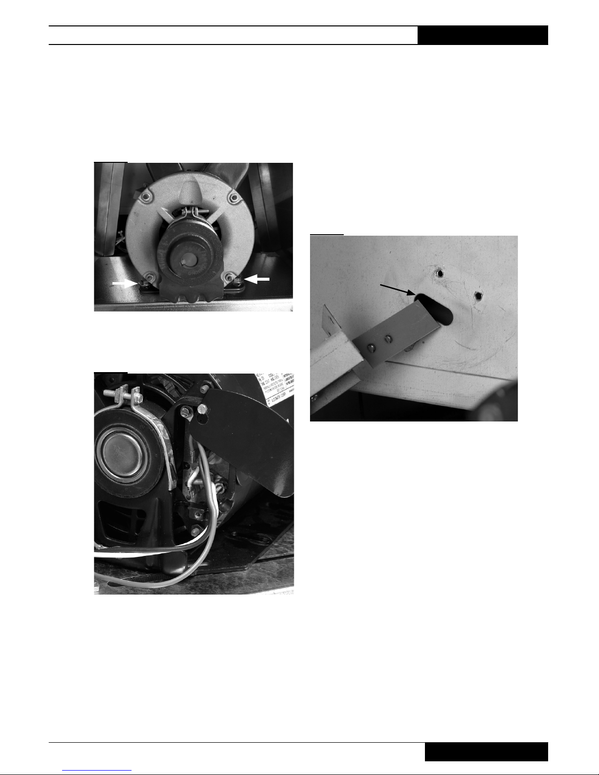
Fan Motor
1. Remove the belt guard.
2. Remove the fan belt.
3. Remove the four bolts and washers from the motor
mount fl anges. See Fig.19.
FIG. 19
4. Open the electrical access panel on the motor and
disconnect the motor wiring. See Fig. 20.
FIG. 20
5. Remove the motor pulley from the motor shaft.
• When reinstalling the motor, ensure the motor
pully is fl ush to the shaft end of the motor.
Air Proving Switch
1. The air proving switch is located on the the side panel
of the fan housing, adjacent to the fan motor, inside the
louvered door end of the heater.
2. Remove the screws that secure the switch bracket to
the fan housing panel and turn switch assembly so the
paddle on the switch arm can be pulled through oblong
hole on side of fan housing. See Fig. 21.
3. Disconnect the leads from the air proving switch.
FIG. 21
If the air proving switch contacts are closed on a call for
heat before the fan motor starts, or do not close after the
fan motor starts, the igniter will not spark nor will the gas
valve open.
Oblong Hole
Premier Ductable Heaters
www.lbwhite.com
Owner’s Manual • Premier 350
24
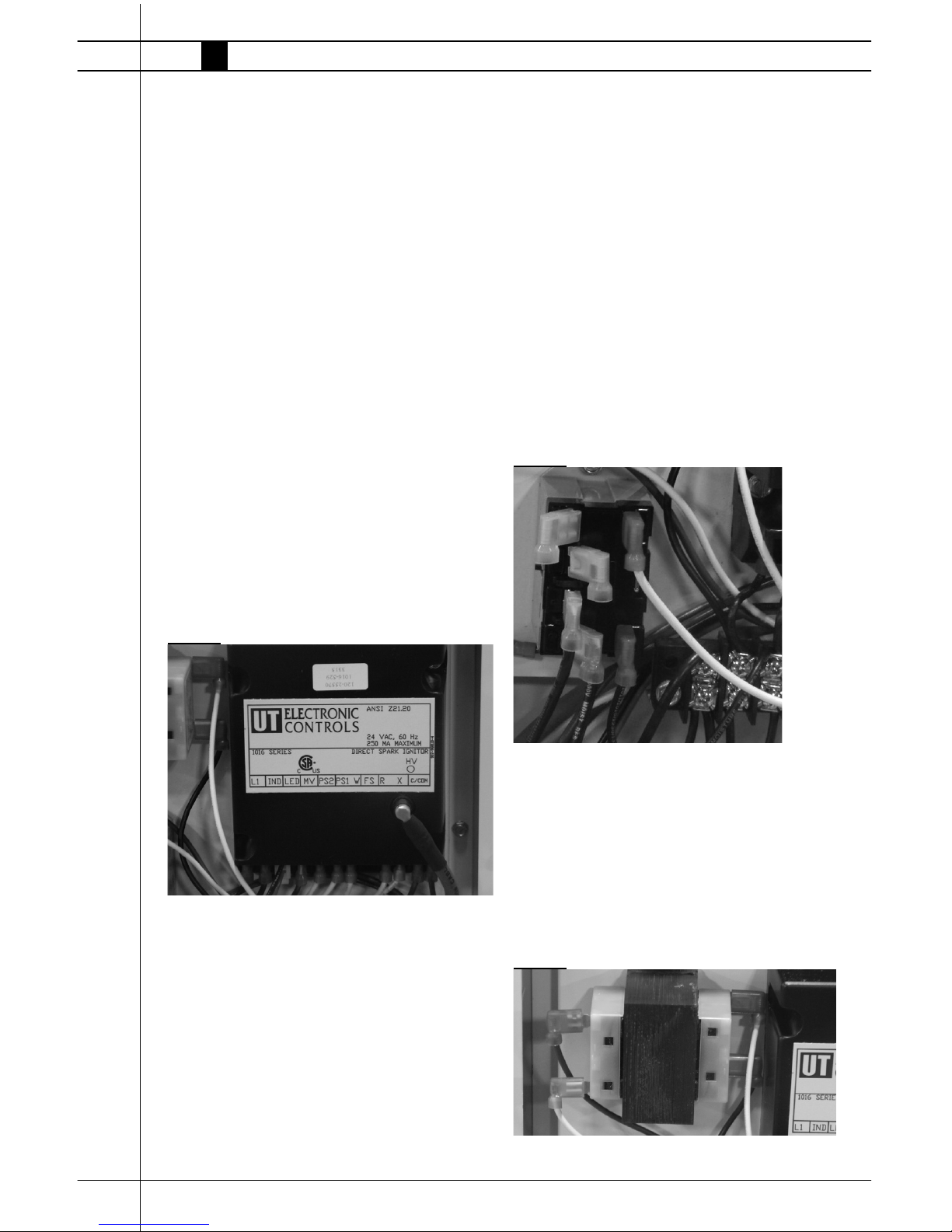
Ignition Control
The control sends and receives voltages to operate or
verify operation of components. Refer to the following
and Fig. 22 to understand the ignition control’s terminal
designators if doing voltage checks on the control.
L1: Main power supply voltage to control.
IND: Main power supply voltage from control to motor.
LED: Wire connection to red light of selector switch.
MV: 24 VAC from ignition control through both high
limit switches to gas control valve.
PS2: 24 VAC return from air proving switch back to
ignition control.
PS1: 24 VAC from ignition control to air proving switch.
W: 24 VAC return from thermostat to ignition control
FS: No terminal.
R: 24 VAC from ignition controller to thermostat.
X: 24 VAC from transformer to ignition controller
(without 24 VAC the contoller will not function.
C/COM: Earth ground for transformer and ignition
control.
Also refer to “Operation Sequence” within this manual
as needed to understand operation of the ignition
control during a call for heat.
FIG. 22
Relay
The relay is responsible for supply of power to the motor. Numbers adjacent to its male terminals for
reference of voltage received and supplied for troubleshooting. Refer to Fig. 23 and the following table for
connection of wiring and voltage checks.
Terminal Function
2 Not used.
4 Not used.
6 115 VAC from relay to start fan motor
8 115 volts to relay from power supply
0 Neutral for relay
1 115 VAC from ignition controller
(IND) to relay for coil closure
If the relay is receiving 115 volts at terminal 8 from
the the power supply, along with 115 volts from
the ignition control at terminal 1, but voltage is not
supplied to the motor from terminal 6, the relay is
defective.
FIG. 23
Transformer
The transformer reduces main power supply voltage
FIG. 24 to 24 VAC for operation of the the ignition
control.
Without 24 VAC from the transformer, the ignition
control will not function, nor will the heater operate.
FIG. 24
0
2
4
6
8
1
Premier Ductable Heaters
Owner’s Manual • Premier 350
25
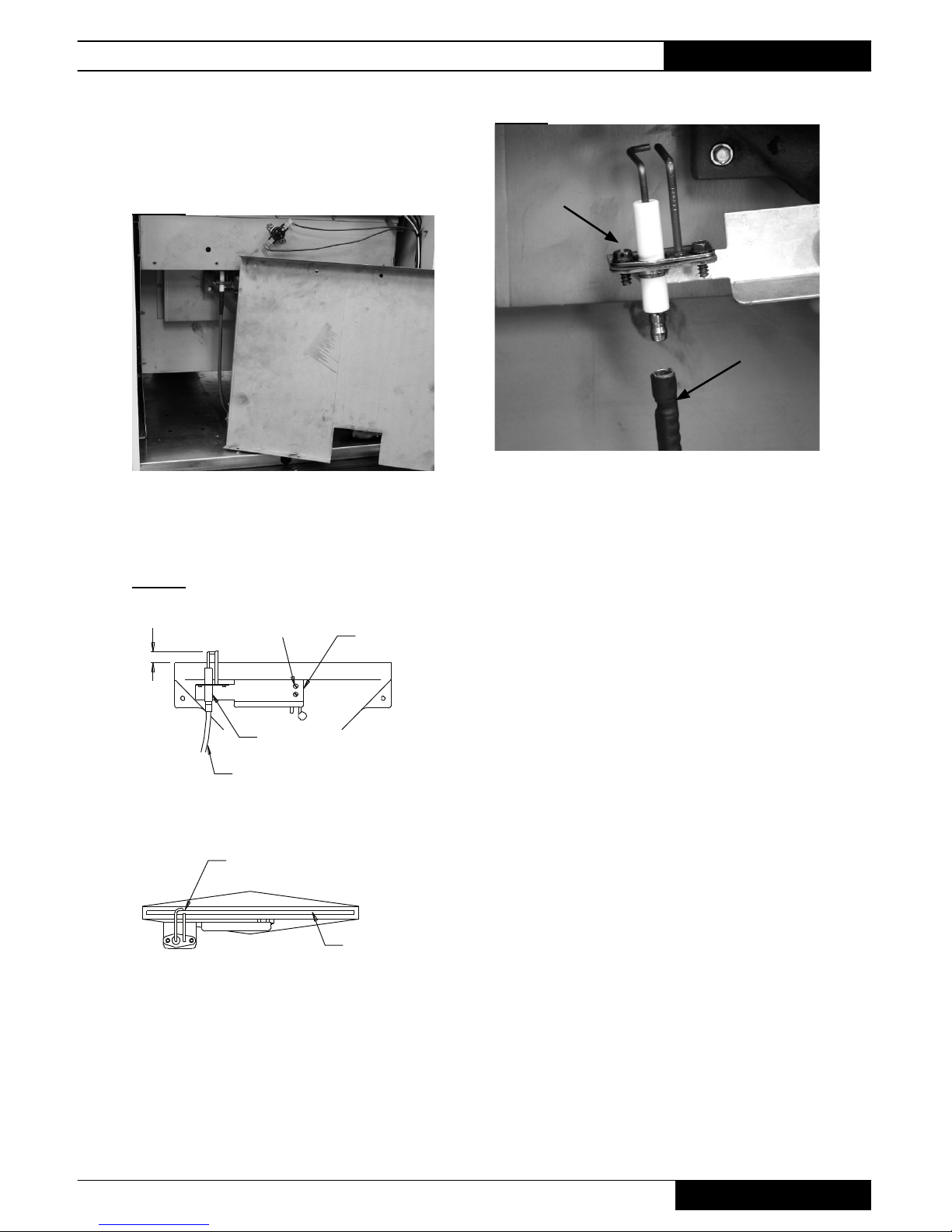
Igniter Assembly
1. Remove burner access panel. See Fig. 25.
FIG. 25
2. The igniter assembly is located at the top of the burner
casting. Remove the two screws securing the mounting
bracket to the burner. See Fig. 26.
FIG. 26
3. Disconnect high voltage ignition lead. Remove the
screws. See Fig. 27.
3/16 IN (4mm) IGNITOR BOTTOM
TO BURNER TOP
SCREWS
MOUNTING
BRACKET
IGNITOR/SENSOR
IGNITOR CABLE
ELECTRODE GAP IS 1/8 IN
AND CENTERED OVER BURNER PORT
BURNER
PORT
FIG. 27
The igniter and ground rod should be cleaned during
routine maintenance to maintain proper ignition.
-- Use steel wool or emery cloth.
-- Rub briskly to remove buildup of dust, dirt,
and oxide.
■ Check the igniter’s ceramic base for cracks.
-- Replace the igniter if cracks are found.
Screws
FRONT VIEW
TOP VIEW
Ignition Lead
Premier Ductable Heaters
www.lbwhite.com
Owner’s Manual • Premier 350
26
Manual Reset High Limit
Switches
This heater has two high limit switches. One is located at
the burner end of the heater on the heat chamber. See
Fig. 28. The other is located on the fan housing behind
the fan motor. See Fig. 29.
FIG. 28
FIG. 29
Their purpose is to safely shut the heater down if the
heater should overheat.
Burner end limit: Protects the burner and associated wiring from overheating caused by excessive gas
pressure.
WARNING
Burn Hazard
■ Do not operate the heater with the high limit
switch bypassed.
■ Operating the heater bypassed high limit switch
may lead to overheating, possibly resulting in a
fi re, with subsequent damage to the heater or
property damage.
Burner End Limit
Motor end limit: Protects from overheating if
the duct is kinked or restricted, or if the air inlet is
blocked.
The switches are wired in series and will disconnect power to the gas control valve if either senses
an overheat condition.
Both high limit switches should be tested a minimum of once per year when the heater is given a
thorough cleaning.
1. Remove the high limit switches from the heater.
Also remove the red cap from both switches.
The burner end limit switch has a washer located
between each leg of the limit switch and the
heat chamber. The washers act as spacers and
prevent the switch from tripping prematurely.
Both must be reinstalled after conducting this
test. See Fig. 30.
FIG. 30
2. Holding a switch by one of its mounting legs,
apply a small fl ame only to the sensing portion
on the back of the switch.See Fig. 31. Be careful
not to melt the plastic housing of the switch
when conducting this test.
FIG. 31
RESET BUTTON
SENSING
SURFACE
TERMINAL
FLAME
MOUNTING
LEG
3. Within a minute, you should hear the contacts of
the switch have opening.
Washers
(#8 - 3/16 ID x
7/16 OD x .041
Thickness)
Premier Ductable Heaters
Owner’s Manual • Premier 350
27
4. Allow the switch to cool for about a minute before fi rmly
pressing its reset button. Put the red cap back on the
switch.
5. Check for electrical continuity across the switch termi-
nals to make sure the contacts have closed.
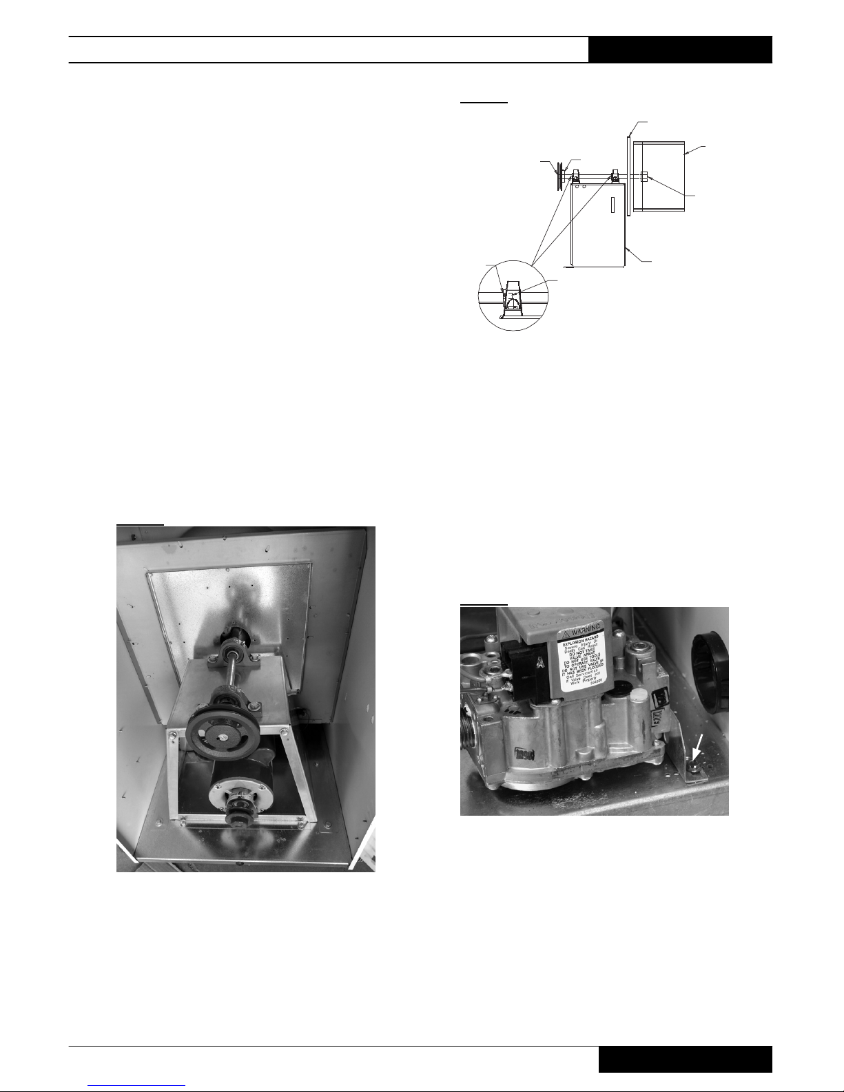
Fan Wheel, Bearings
and Shaft
1. Remove the following:
a. Belt guard and belt.
b. Bolts and washers securing the bearing platform at
the heater’s base.
c. Screws securing the fan panel to the fan housing.
2. Slide the complete assembly from the heater.
3. Replace the components as needed
4. When reinstalling, ensure fan shaft is fl ush with fan hub
and fan pulley. See Fig. 33.
FIG. 32
FIG. 33
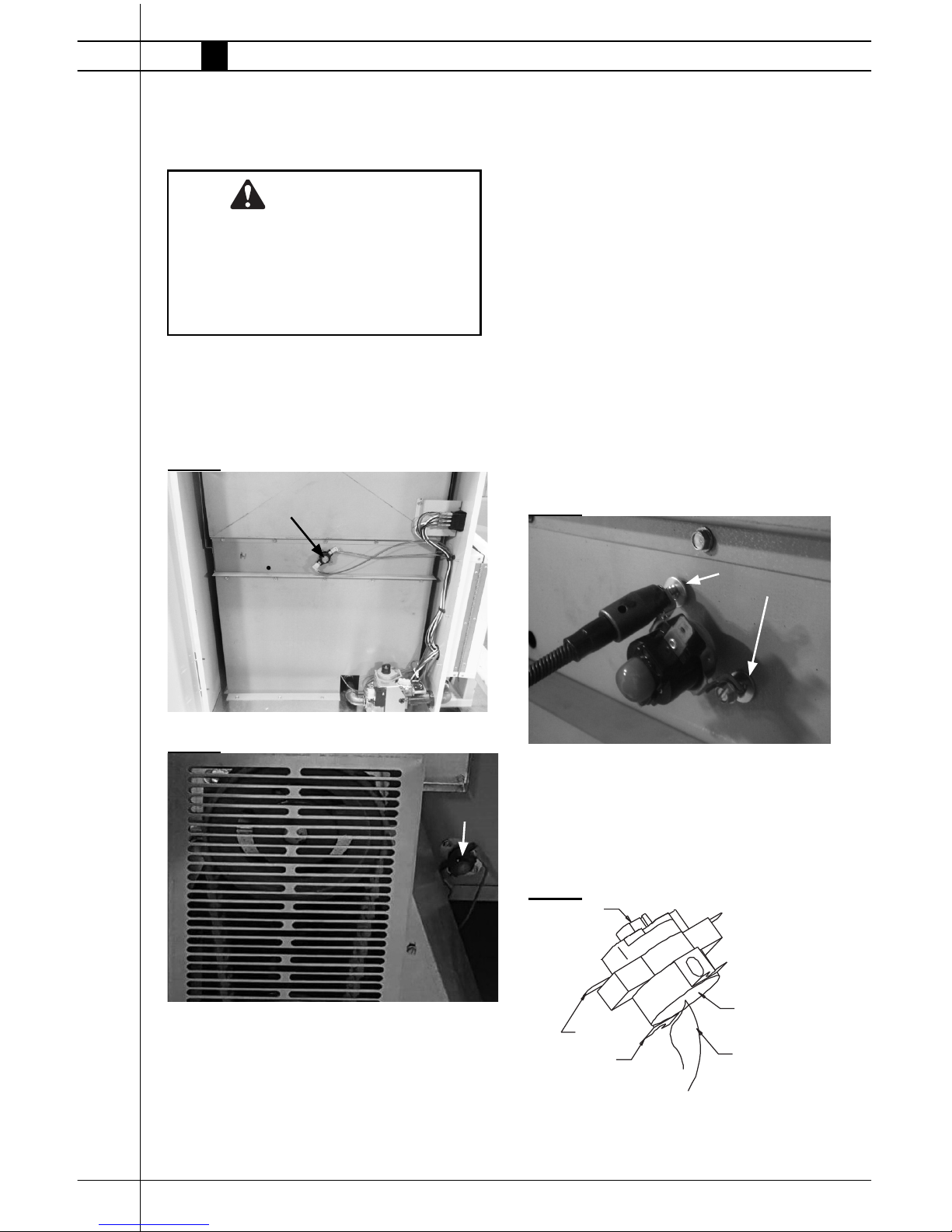
Burner Orifice and Gas
Control Valve
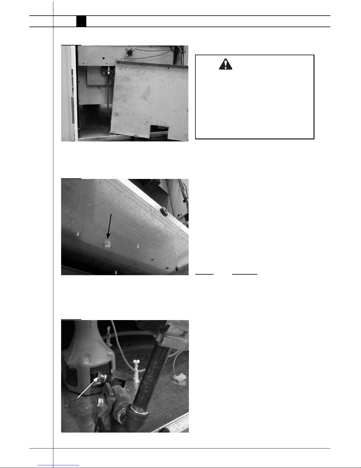
1. Remove hose and pipe nipple from control
valve inlet.
2. Open burner end door.
3. Remove screws from gas control bracket and
disconnect control valve’s electrical wiring. See
Fig. 34.
FIG. 34
4. Remove burner access panel. See Fig. 35.
PULLEY HUB
SHAFT PULLEY FLUSH
WITH SHAFT END
BEARING RACE FLUSH
WITH FRONT EDGE
OF SHAFT FLAT.
SET SCREWS TIGHTENED
TO FLATS.
SHAFT FLAT
MAIN SUPPORT
FAN HUB
FLUSH WITH
SHAFT END
FAN WHEE
L
FAN PANEL FLANGES
TOWARD PULLEY
Screws
Fan Panel
Bearing
Platform
Premier Ductable Heaters
www.lbwhite.com
Owner’s Manual • Premier 350
28
FIG. 35
5. Remove burner retaining bolt from under base at gas
control end of heater. See Fig. 36.
FIG. 36
6. Lift and pivot the gas train assembly so orifi ce is
exposed. See Fig. 37, Dual Fuel shown. Replace control
valve or orifi ce if needed.
FIG. 37
Bolt
Orifi ce
WARNING
Burn Hazard
■ Do not disassemble the gas control valve.
■ Do not attempt to replace any components of the
gas control valve.
■ The gas control valve must be replaced if any
physical damage occurs to the control valve
assembly.
■ Failure to follow this warning will result in fi re
or explosions, leading to injury or death to
humans, and property damage.
ATTENTION
■ The following explains a typical procedure to be
followed in checking gas pressures.
■ The gas pressures will vary depending upon fuel
type.
■ Consult the dataplate on the heater or page 4 in
this manual for specifi c pressures to be used in
conjunction with this procedure.
■ Gas pressure measured at the inlet to the gas valve
is Inlet Pressure and gas pressure measured at the
outlet of the gas valve is Burner Manifold Pressure.
MATERIALS REQUIRED
Quantity Description
2 Gas pressure gauges capable of
reading up to 35 in.W.C./8.7 kPa.
(Available from L.B.White Company
if desired)
A. Preparation
1. Disconnect the heater from the electrical supply
and close the fuel supply valve to the heater.
2. Open the case access panel at burner end of
heater.
3. Brush or blow off any dust or dirt in the vicinity of
the gas control valve.
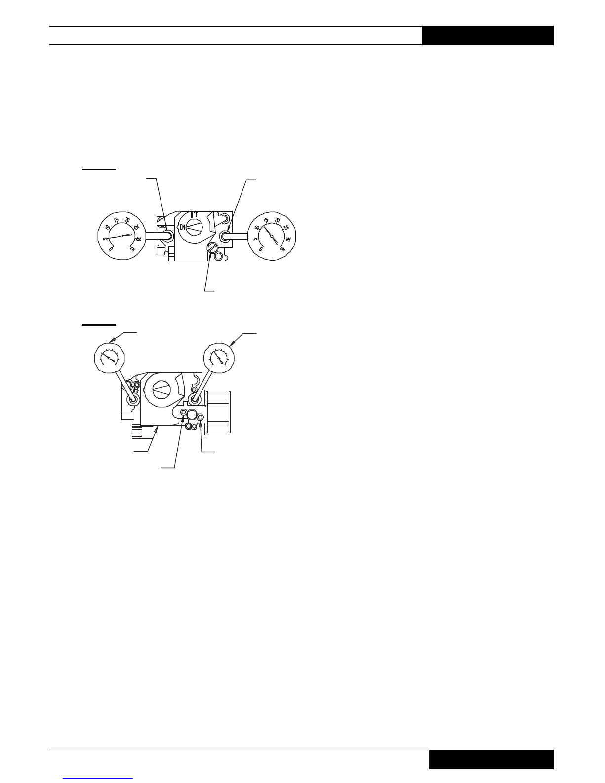
B. Gauge Installation
1. Locate the gas control pressure taps. See Fig.
38 for single stage valve, or Fig. 39 for two stage
valve. Remove the pressure tap plugs using a 3/16
in. allen key.
Gas Pressure Checks
Premier Ductable Heaters
Owner’s Manual • Premier 350
29
2. Securely connect pressure gauges at these points.
3. Open the fuel supply valves to the heater and reconnect the heater electrical supply.
4. Start the heater
FIG. 38
OUTLET PRESSURE TAP
INLET PRESSURE TYPE
INTERNAL PRESSURE REGULATOR
GAUGE AT VALVE INLET
GAUGE AT VALVE OUTLET
FIG. 39
OUTLET
GAUGE
INLET
GAUGE
GAS CONTROL
LOW HEAT
HIGH HEAT
OFF
ON
LO
HI
0
5
10
15
20
25
30
35
0
5
10
15
20
25
30
35
C. Reading Pressures
1. With the heater operating, the pressure gauges should
read the pressures specifi ed on the dataplate.
2. Do the readings at the inlet and outlet pressure gauges
agree with that specifi ed on the dataplate? If so, then
no further checking or adjustment is required. Proceed
to section D.
3. If the inlet pressures do not agree with that specifi ed
on the dataplate, then the regulator controlling gas
pressure to the heater requires adjustment.
4. If the inlet pressure is correct but the burner manifold
pressure does not agree with that specifi ed on the
dataplate, then the gas control valve’s internal pressure
regulator needs adjustment:
Premier 350DF Heater:
-- Remove the regulator cap on the control valve.
-- Using a standard screwdriver turn the adjusting
screw clockwise (to increase pressure) or counterclockwise
(to decrease pressure) until the burner manifold
pressure is set.
-- Install regulator cap.
-- Proceed to COMPLETION.
Premier 350 Propane Gas Heater
-- Turn the thermostat down to its lowest setting.
-- Remove the cap from the high and low heat adjusting screws at the two stage pressure regulator on
the gas control valve.
-- Slowly turn up the thermostat until a pressure is read
no greater than 2.0 in.W.C./.49 kPa at the outlet
pressure gauge.
-- If less than these pressures is observed, the low
heat setting at the regulator on the gas control will
require adjusting.
-- Turn clockwise to increase, or counterclockwise to
decrease pressure.
-- Turn the thermostat completely up.
-- You should see the gas pressure increase from 2.0
in. W.C./ .49 kPa at low heat to 8.0 in.W.C./2.0 kPa
high heat.
-- If less or greater than these pressure are observed
the high heat setting must be adjusted clockwise or
counterclockwise accordingly until proper pressure
is achieved.
D. Completion
1. Once the proper inlet and burner manifold pressures
have been confi rmed and/or properly set, close the
fuel supply valve to the heater and allow the heater
to burn off any gas remaining in the gas supply line.
2. Disconnect the heater from its electrical supply and
close fuel supply valve.
3. Remove the gauges.
4. Install pressure tap plugs.
5. Open fuel supply valve and reconnect electrical
supply to heater. Start the heater and check for gas
leaks.
6. Set thermostat to desired temperature.
SINGLE STAGE
TWO STAGE
Premier Ductable Heaters
www.lbwhite.com
Owner’s Manual • Premier 350
30
Troubleshooting Guide
READ THIS ENTIRE SECTION
BEFORE BEGINNING TO
TROUBLESHOOT PROBLEMS.
The following troubleshooting guide provides
systematic procedures for isolating equipment
problems. This guide is intended for use by a
QUALIFIED GAS HEATER SERVICE PERSON.
DO NOT ATTEMPT TO SERVICE THESE HEATERS UNLESS YOU HAVE BEEN PROPERLY
TRAINED.
TEST EQUIPMENT REQUIRED
The following pieces of test equipment will be
required to troubleshoot this system with minimal
time and effort.
• Digital Multimeter - for measuring AC
voltage and resistance.
• Low Pressure Gauge - for checking inlet
and outlet pressures at the gas control valve
against dataplate rating.
■ Visually inspect equipment for apparent
damage.
■ Checking all wiring for loose connections and
worn
Refer to the system operation sequence in this
section to gain an understanding as to how the
equipment operates during a call for heat. Understanding the sequence of operation of the ignition
module and related components is esential as it
will relate directly to problem solving provided by
the fl ow charts.
The ignition control module is self-diagnostic. The
red light, located within the selector switch, will
fl ash a specifi c light pattern depending upon the
problem which is diagnosed. To effectively use
the fl ow charts, you must fi rst identify what the problem
is by the light pattern of the L.E.D. (light emitting diode)
diagnostic light. If the light is fl ashing, the fl ash pattern
will be followed by a pause and then a repeat of the
fl ash pattern until the problem is corrected. Refer to
the tables below to identify what page to refer to when
troubleshooting any problems.
The L.E.D. light will only be on when the selector switch
is positioned to HEAT and the thermostat is set above
room temperature. The light will not be on when the
selector switch is positioned to VENT.
Heating Mode Problems Page
L.E.D. light is not on ........................................... 32
L.E.D. diagnostic light is fl ashing:
A. One Time........................................................ 33
B. Two Times ...................................................... 34
C. Three Times ................................................... 35
D. Four Times ..................................................... 35
E. Five Times ...................................................... 35
Ventilation Mode Problems Page
A. Motor Does Not Run ...................................... 36
B. Motor “Hums,” Does Not Run ......................... 36
C. Motor Runs with Low Air Output .................... 36
Components should be replaced only after each step
has been completed and replacement is suggested in
the fl ow chart. Refer to the Servicing sections as neces-
sary to obtain information on disassembly and replacement procedures of the component once the problem is
identifi ed by the fl ow chart.
DIRECT IGNITION OPERATION
SEQUENCE:
-- Selector switch is set to heat.
-- Line voltage is sent to ignition control and to
transformer.
-- Transformer reduces line voltage to 24 volts which is
sent to thermostat.
-- The thermostat calls for heat.
-- The thermostat sends 24 volts to ignition control.
-- Red light is illuminated
-- Ignition control module performs self safety check.
-- Internal components are tested.
-- Air proving circuit is checked.
-- Ignition control module begins ignition trial sequence.
-- Ignition control module sends 24 volts to air proving
switch.
-- Ignition control sends line voltage to motor relay
-- Motor relay closes and fan motor starts.
-- Air proving switch closes and 24 volts are returned to
the ignition control module.
WARNING
■ This heater can start at any time.
■ Troubleshooting this system may require
operating the unit with line voltage present and
gas on. Use extreme caution when working on
the heater.
■ Failure to follow this warning may result in
property damage, personal injury or death.
 Loading...