

L.B. White Tradesman CP400, Tradesman CP170 Owner's Manual And Instructions

Attention
This heater has been tested and
evaluated by the CSA Group in
accordance with the requirements
of Standard ANSI Z83.7 • CSA 2.14
and is listed and approved as a
direct gas-fi red forced-air
construction heater with application
for the temporary heating of buildings under construction, alteration,
or repair. The heater shall NOT
be used with ductwork. CHECK
WITH YOUR LOCAL FIRE SAFETY
AUTHORITY, YOUR LOCAL FUEL
GAS SUPPLIER, OR THE
L.B. WHITE COMPANY IF YOU
HAVE QUESTIONS REGARDING
APPLICATIONS.
This Owner’s Manual provides
instructions for Tradesman
propane-vapor and natural gas
heaters. Instructions pertaining to
a specifi c model or gas confi gura-
tion are noted. Unless noted, the
information applies to all versions of
Tradesman heaters.
www.lbwhite.com
SCAN THIS
with your smartphone or
visit http://goo.gl/nvneR
to view maintenance
videos for L.B.White heaters.*
WORLD PROVIDER - INNOVATIVE HEATING SOLUTIONS
411 Mason Street, Onalaska, WI, U.S.A 54650 • 800-345-7200 • 608-783-5691 • 608-783-6115 (fax) • www.lbwhite.com
Congratulations!
You have purchased the fi nest portable forced air construction
heater available. Your new L.B. White heater incorporates the
benefi ts from the most experienced manufacturer of heating
products using state-of-the-art technology.
We, at L.B. White, thank you for your confi dence in our products
and welcome any suggestions or comments you may have...
call us, toll-free, at (800) 345-7200.
Tradesman
Standard and Ultra
Construction Heater
Model
CP170
CP400
CP170
Btu/h/kW
170,000/49.8
400,000/117.2
155,000/45.4
Fuel
Propane Vapor
Withdrawal
Natural Gas
Owner’s Manual and Instructions
View this manual online at www.lbwhite.com
* Requires an app like QR Droid
for Android or for iPhone
SEE ASSEMBLY
INSTRUCTIONS
INSIDE
Please refer to important
elevation information on
inside cover.
North
American
Made

Tradesman Construction Heaters
www.lbwhite.com
Owner’s Manual • Tradesman
2
TABLE OF CONTENTS
Heater Specifi cations ...................................................................................................... 4
General Information ........................................................................................................ 5
Safety Precautions ......................................................................................................... 6
General Installation Instructions ..................................................................................... 9
Propane Gas Supply Sizing ............................................................................................ 11
Handle Assembly ............................................................................................................ 12
Hose and Regulator Assembly ....................................................................................... 12
Connecting Regulator to Propane Gas Supply Cylinder ................................................ 13
Height Adjustment (Tradesman 170) .............................................................................. 13
Start-Up Instructions ....................................................................................................... 14
Shut-Down Instruction .................................................................................................... 14
Variable Rate Valve ........................................................................................................ 14
Cleaning Instructions ...................................................................................................... 14
Maintenance Instructions ................................................................................................ 15
Service Instructions ........................................................................................................ 15
Motor, Fan, and Air Proving Switch ................................................................................ 16
Auto Reset Limit Switches .............................................................................................. 16
Igniter .............................................................................................................................. 17
Thermostat ..................................................................................................................... 18
Ignition Control ............................................................................................................... 18
Variable Rate Valve and Gas Control Valve ................................................................... 19
Gas Pressure Checks ..................................................................................................... 19
Burner Orifi ce ................................................................................................................. 20
Troubleshooting Information ........................................................................................... 22
Electrical Connection and Ladder Diagrams
Tradesman 170 Standard ..................................................................................... 31
Tradesman 170 Ultra and Tradesman 400 ........................................................... 32
Heater Component Function .......................................................................................... 33
Parts Identifi cation
Tradesman 170 Parts Schematic and Parts List .................................................. 34/35
Tradesman 400 Parts Schematic and Parts List .................................................. 36/37
Warranty Policy............................................................................................................... 39
Replacement Parts and Service ..................................................................................... 39
WARNING
Standard products are manufactured to operate at optimum effi ciency at elevations
between 0 and 2000 ft. (0-610m) above sea level.
If operated at higher elevations the product will not function correctly and may
function in an unsafe nature.
Products providing proper operation for alternate elevations may be available.
If you require a high elevation product, did not specify when ordering, and/or the
box this unit came in does not have an alternate altitude designation sticker please
contact technical support.
Tradesman Construction Heaters
Owner’s Manual • Tradesman
3
WARNING
FIRE, BURN, INHALATION, AND
EXPLOSION HAZARD
■ KEEP SOLID COMBUSTIBLES A SAFE
DISTANCE AWAY FROM THE HEATER.
■ SOLID COMBUSTIBLES INCLUDE WOOD,
PAPER, OR PLASTIC PRODUCTS, BUILDING
MATERIALS, AND DUST.
■ DO NOT USE THE HEATER IN SPACES WHICH
CONTAIN OR MAY CONTAIN VOLATILE OR
AIRBORNE COMBUSTIBLES.
■ VOLATILE OR AIRBORNE COMBUSTIBLES
INCLUDE GASOLINE, SOLVENTS, PAINT
THINNER, DUST PARTICLES OR UNKNOWN
CHEMICALS.
■ FAILURE TO FOLLOW THESE INSTRUCTIONS
MAY RESULT IN A FIRE OR EXPLOSION.
■ FIRE OR EXPLOSIONS CAN LEAD TO
PROPERTY DAMAGE, PERSONAL INJURY OR
DEATH.
FOR YOUR
SAFETY
If you smell gas:
1. Open windows.
2. Don’t touch electrical
switches.
3. Extinguish any open fl ame.
4. Immediately call your gas
supplier.
FOR YOUR
SAFETY
Do not store or use gasoline
or other fl ammable vapors
and liquids in the vicinity of
this or any other appliance.
GENERAL HAZARD WARNING
■ FAILURE TO COMPLY WITH THE PRECAUTIONS AND INSTRUCTIONS PROVIDED WITH
THIS HEATER CAN RESULT IN:
— DEATH
— SERIOUS BODILY INJURY OR BURNS
— PROPERTY DAMAGE OR LOSS FROM FIRE OR EXPLOSION
— ASPHYXIATION DUE TO LACK OF ADEQUATE AIR SUPPLY OR CARBON MONOXIDE
POISONING
— ELECTRICAL SHOCK
■ READ THIS OWNER’S MANUAL BEFORE INSTALLING OR USING THIS PRODUCT.
■ ONLY PERSONS WHO CAN READ, UNDERSTAND, AND FOLLOW THE INSTRUCTIONS
SHOULD USE OR SERVICE THIS HEATER.
■ SAVE THIS OWNER’S MANUAL FOR FUTURE USE AND REFERENCE.
■ OWNER’S MANUALS AND REPLACEMENT LABELS ARE AVAILABLE AT NO CHARGE. SEE
WEBSITE, OR FOR ASSISTANCE, CONTACT L.B. WHITE AT 1-800-345-7200.
WARNING
■ PROPER GAS SUPPLY PRESSURE MUST BE PROVIDED TO THE INLET OF THE HEATER.
■ REFER TO DATA PLATE FOR PROPER GAS SUPPLY PRESSURE.
■ GAS PRESSURE IN EXCESS OF THE MAXIMUM INLET PRESSURE SPECIFIED AT THE
HEATER INLET CAN CAUSE FIRES OR EXPLOSIONS.
■ FIRES OR EXPLOSIONS CAN LEAD TO SERIOUS INJURY, DEATH, OR BUILDING
DAMAGE.
■ GAS PRESSURE BELOW THE MINIMUM INLET PRESSURE SPECIFIED AT THE HEATER INLET
MAY CAUSE IMPROPER COMBUSTION.
■ IMPROPER COMBUSTION CAN LEAD TO ASPHYXIATION OR CARBON MONOXIDE POISONING AND THEREFORE SERIOUS INJURY OR DEATH.
WARNING
FIRE AND EXPLOSION HAZARD
■ NOT FOR HOME OR RECREATIONAL VEHICLE USE.
■ INSTALLATION OF THIS HEATER IN A HOME OR RECREATIONAL VEHICLE MAY RESULT IN A
FIRE OR EXPLOSION.
■ FIRE OR EXPLOSIONS CAN CAUSE PROPERTY DAMAGE OR LOSS OF LIFE.
Tradesman Construction Heaters
www.lbwhite.com
Owner’s Manual • Tradesman
4
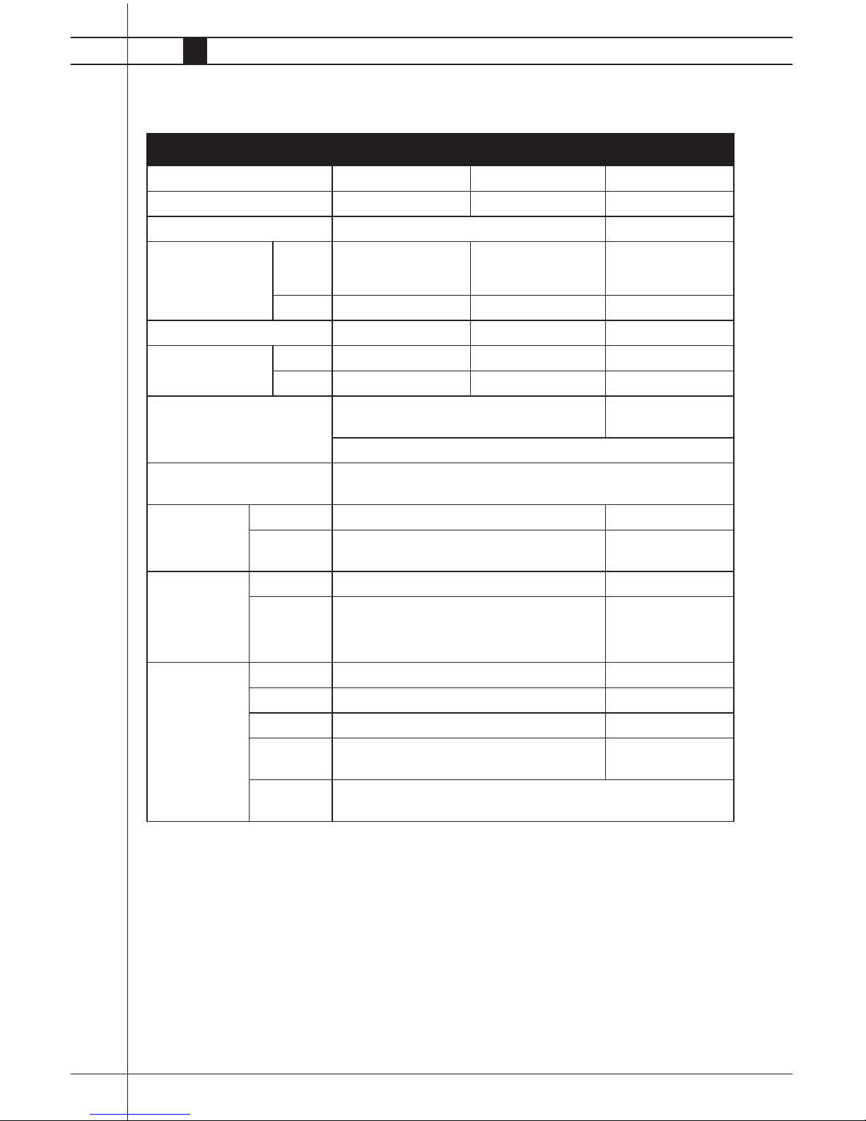
Specifications
CP170 CP400
Propane Gas Natural Gas Propane Gas
Maximum Input (Btuh/kW) 170,000/49.8 155,000/45.4 400,000/117.2
Minimum Input (Btuh/kW) 125,000/36.6 250,000/73.3
Inlet Gas Supply
Pressure Acceptable
at the Gas Connection of the Heater
Max 11.1 in. W.C./2.74 kPa 13.5 in. W.C./3.36
kPa*
5.2 PSIG/35.74 kPa
Min 11.1 in. W.C./2.74 kPa 7.0 in. W.C./1.74 kPa* 5.2 PSIG/35.74 kPa
Burner Manifold Pressure 11.0 in. W.C./2.74 kPa 5.5 in. W.C./1.37 kPa 5.2 PSIG/35.74 kPa
Fuel Consumption
Per Hour
Max 7.89 lbs./3.57 kg 155 ft.³/4.39 m³ 18.5 lbs./8.39 kg
Min 5.8 lbs./2.63 kg 125 ft.³/4.39 m³ 11.6 lbs. / 5.26 kg
Motor Characteristics 1/15 H.P. / 44.7 watts 1/5 H.P. / 149 watts
3,300 RPM
Sleeve Bearing
Electrical Supply
(Volts/Hz/Phase)
120/60/1
Amp Draw Starting 3.7 4.0
Continuous
Operation
1.0 1.3
Dimensions Inches 24 x 10 x 16 34.5 x 12.5 x 19.5
Centimeters 61 x 25.4 x 40.6 87.5 x 31.7 x 49.5
Minimum Safe
Distances
From Nearest
Combustible
Materials (feet/
meters)
TOP 6 / 1.83 7 / 2.43
SIDES 3 / 0.9 5 / 1.52
BACK 3 / 0.9 5 / 1.52
BLOWER
OUTLET
10 / 3.05 15 / 4.57
GAS
SUPPLY
Propane Gas Supply - 6 ft./ U.S, 10 ft./3.04 m Canada
Natural Gas Supply - N/A
* The gas connection for Tradesman 170 Natural Gas heaters is the inlet of the gas
regulator supplied with the heater.

Tradesman Construction Heaters
Owner’s Manual • Tradesman
5
This Owner’s Manual includes all options and accessories commonly used on this heater.
When calling for technical service assistance, or for
other specifi c information, always have model num-
ber, confi guration number and serial number avail-
able. This information is contained on the dataplate.
This manual will instruct you in the operation and
care of your unit. Have your qualifi ed installer review
this manual with you so that you fully understand the
heater and how it functions.
The gas supply line installation, installation of the
heater, and repair and servicing of the heater requires
continuing expert training and knowledge of gas
heaters and should not be attempted by anyone who
is not so qualifi ed.
Contact your local L.B. White distributor or the L.B.
White Co., Inc. for assistance, or if you have any
questions about the use of the equipment or its
application.
The L.B. White Co., Inc. has a policy of continuous
product improvement. It reserves the right to change
specifi cations and design without notice.
General Information
Tradesman Construction Heaters
www.lbwhite.com
Owner’s Manual • Tradesman
6
Propane gas and natural gas have man-made odorants added specifi cally for detection of fuel gas leaks.
If a gas leak occurs, you should be able to smell
the fuel gas. THAT’S YOUR SIGNAL TO GO INTO
IMMEDIATE ACTION!
■ Do not take any action that could ignite the fuel
gas. Do not operate any electrical switches. Do not
pull any power supply or extension cords. Do not
light matches or any other source of fl ame. Do not
use your telephone.
■ Get everyone out of the building and away from the
area immediately.
■ Close all propane gas tank or cylinder fuel supply
valves, or the main fuel supply valve located at the
meter if you use natural gas.
■ Propane gas is heavier than air and may settle in
low areas. When you have reason to suspect a
propane leak, keep out of all low areas.
■ Use your neighbor’s phone and call your fuel gas
supplier and your fi re department. Do not re-enter
the building or area.
■ Stay out of the building and away from the area
until declared safe by the fi refi ghters and your fuel
gas supplier.
■ FINALLY, let the fuel gas service person and the
fi refi ghters check for escaped gas. Have them
air out the building and area before you return.
Properly trained service people must repair the
leak, check for further leakages, and then relight
the appliance for you.
■ Some people cannot smell well. Some people
cannot smell the odor of the man-made chemical added to propane or natural gas. You must
determine if you can smell the odorant in these
fuel gases.
■ Learn to recognize the odor of propane gas and
natural gas. Local propane gas dealers will be
more than happy to give you a scratch and sniff
pamphlet. Use it to become familiar with the fuel
gas odor.
■ Smoking can decrease your ability to smell. Being
around an odor for a period of time can affect your
sensitivity to that particular odor.
■ The odorant in propane gas and natural gas is colorless and the intensity of its odor can fade under
some circumstances.
■ If there is an underground leak, the movement of
gas through the soil can fi lter the odorant.
■ Propane gas odor may differ in intensity at different
levels. Since propane gas is heavier than air, there
may be more odor at lower levels.
■ Always be sensitive to the slightest gas odor. If you
continue to detect any gas odor, no matter how
small, treat it as a serious leak. Immediately go into
action as discussed previously.
Fuel Gas Odor
Safety Precautions
Odor Fading - No
Odor Detected
WARNING
Asphyxiation Hazard
■ Do not use this heater for heating human living quarters.
■ Do not use in unventilated areas.
■ The fl ow of combustion and ventilation air must not be obstructed.
■ Proper ventilation air must be provided to support the combustion air requirements of the heater
being used.
■ Refer to the specifi cation section of the Owner’s Manual, heater’s dataplate, or contact the LB
White Company to determine combustion air ventilation requirements of the heater.
■ Lack of proper ventilation air will lead to improper combustion.
■ Improper combustion can lead to carbon monoxide poisoning in humans leading to serious injury
or death. Symptoms of carbon monoxide poisoning can include headaches, dizziness and diffi culty
in breathing.
■ Proper ventilation air for combustion must be provided in accordance with OSHA 29 CFR
1926.154, Temporary Heating Devices, ANSI A10.10, Safety Requirements for Temporary and
Portable Space Heating Devices, or the Natural Gas and Propane Installation Code, CAN/CSA
B149.1 as appropriate.

Tradesman Construction Heaters
Owner’s Manual • Tradesman
7
■ Propane gas has a distinctive odor. Learn to
recognize these odors. (Reference Fuel Gas Odor
and Odor Fading sections above.
■ If you have not been properly trained in repair and
service of propane gas then do not attempt to light
heater, perform service or repairs, or make any
adjustments to the heater on the propane gas fuel
system.
■ Even if you are not properly trained in the service
and repair of the heater, ALWAYS be consciously
aware of the odors of propane gas and natural gas.
■ A periodic sniff test around the heater or at the
heater’s joints; i.e. hose, connections, etc., is a
good safety practice under any conditions. If you
smell even a small amount of gas, CONTACT
YOUR FUEL GAS SUPPLIER IMMEDIATELY. DO
NOT WAIT!
1. Do not attempt to install, repair, or service this
heater or the gas supply line unless you have
continuing expert training and knowledge of gas
heaters.
Qualifi cations for service and installation of this
equipment are as follows:
a. To be a qualifi ed gas heater service person, you
must have suffi cient training and experience to
handle all aspects of gas-fi red heater installation,
service and repair. This includes the task of installation, troubleshooting, replacement of defective
parts and testing of the heater. You must be able
to place the heater into a continuing safe and
normal operating condition. You must completely
familiarize yourself with each model heater by
reading and complying with the safety instructions,
labels, Owner’s Manual, etc., that is provided with
each heater.
b. To be a qualifi ed gas installation person, you must
have suffi cient training and experience to handle
all aspects of installing, repairing and altering gas
lines, including selecting and installing the proper
equipment, and selecting proper pipe and tank size
to be used. This must be done in accordance with
all local, state and national codes as well as the
manufacturer’s requirements.
c. In the Commonwealth of Massachusetts, this
product must be installed by a gas fi tter licensed by
the Commonwealth of Massachusetts.
2. All installations and applications of L.B. White
heaters must meet all relevant local, state and
national codes. Included are L.P. gas, natural gas,
electrical, and safety codes. Your local fuel gas
supplier, a local licensed electrician, the local fi re
department or similar government agencies, or
your insurance agent can help you determine code
requirements.
Also refer to:
-- ANSI/NFPA 58, latest edition, Standard for
Storage and Handling of Liquefi ed Petroleum
Gas
-- ANSI Z223.1/NFPA 54, National Fuel Gas
Code
-- ANSI/NFPA 70, National Electrical Code.
-- CSA C22.1 Part 1, Standard Canadian Electri-
cal Code
-- CSA C22.2 No.3, Electrical Features of Fuel
Burning Equipment
3. Adequate ventilation air for combustion must be
provided.
4. We cannot anticipate every use which maybe
made of our heaters. Check with the local fi re
safety authority if you have questions about
applications.
5. Once the heater has been lit, high surface and
exhaust temperatures can ignite clothing or burn
users who come too close to the heater. When
the heater is in operation, those working around
the heater should never touch the heater or come
within the clearances stated. Use extreme caution
when lighting the heater or adjusting heat levels.
6. Forced air heaters shall not be directed toward any
propane gas container within 20 feet (6.10 meters).
7. Do not wash the heater. Use only compressed air,
a soft brush or dry cloth to clean the interior of the
heater and it’s components.
8. Use only the regulator supplied with the heater.
The heater must be regulated at all times for
proper operation.
Attention - Critical
Points to Remember!

Tradesman Construction Heaters
www.lbwhite.com
Owner’s Manual • Tradesman
8
9. For safety, this heater is equipped with an auto
reset backfl ash switch, and depending on models,
an air proving switch. Never operate the heater
with any safety device that has been bypassed.
Do not operate this heater unless these features
are fully functioning.
10. Do not block air intakes or discharge outlets
of the heater. Doing so may cause improper
combustion or damage to heater components
leading to property damage.
11. The hose assembly shall be visually inspected
on a daily basis after heater relocation and
when the heater is in use. If it is evident there
is excessive abrasion or wear, or if the hose is
cut, it must be replaced prior to the heater being
put into operation. The hose assembly shall be
protected from building materials, and contact
with hot surfaces during use. The replacement
hose assembly shall be that specifi ed by the
manufacturer. See parts list.
12. Check for gas leaks and proper function upon
heater installation, when relocating, and after
servicing. Refer to leak check instructions within
installation section of this manual.
13. This heater should be inspected for proper
operation by a qualifi ed service person before
each use and at least annually.
14. Always turn off the gas supply to the heater if the
heater is not going to be used.
15. This heater is equipped with a three-prong
(grounding) plug for your protection against
shock hazard and must be plugged directly into
a properly grounded three-prong receptacle.
Failure to use a properly grounded receptacle
can result in electrical shock, personal injury,
or death.
16. If gas fl ow is interrupted and fl ame goes out, do
not relight the heater until you are that all gas that
may have accummulated has cleared away. In
any event, do not relight the heater for at least 5
minutes.
17. When the heater is to be stored indoors, the
connection between the propane gas supply container and the heater must be disconnected. The
container must be stored in accordance with the
Standard for the Storage and Handling of Liquifi ed
Petroleum Gases, ANSI/NFPA 58, or CSA B149.,
Natural Gas and Propane Gas Installation Code.
18. Propane gas supply containers have left handed
threads. Always use the appropriate wrench to
make a connection to tighten or loosen the P.O.L.
fi tting at the cylinders’ gas supply valve.
Tradesman Construction Heaters
Owner’s Manual • Tradesman
9
heater due to wind action on the covering or
other material.
7. Insure that all accessories that ship with the
heater have been and installed.
8. Check all connections for gas leaks using approved gas leak detectors. Gas leak testing is
performed as follows:
-- Check all pipe connections, hose connections,
fi ttings and adapters upstream of the gas control
with approved gas leak detectors.
-- In the event a gas leak is detected, check the
components involved for cleanliness and proper
application of pipe compound before further
tightening.
-- Tighten the gas connections as necessary to
stop the leak.
-- After all connections are checked and any leaks
are stopped, turn on the main burner.
-- Stand clear while the main burner ignites to
prevent injury caused from hidden leaks that
could cause fl ashback.
-- With the main burner in operation, check all
connections, hose connections, fi ttings and joints
as well as the gas control valve inlet and outlet
connections with approved gas leak detectors.
-- If a leak is detected, check the components
involved for cleanliness in the thread areas and
proper application of pipe compound before
further tightening.
-- Tighten the gas connection as necessary to stop
the leak.
General Installation Instructions
INSTALLATION INSTRUCTIONS
WARNING
Burn Hazard
Can cause property damage, severe injury or death.
To avoid dangerous accumulation of fuel gas, turn
off gas supply at the appliance service valve before
starting installation, and perform gas leak test after
completion of installation.
1. Read all safety precautions and follow L. B. White
recommendations when installing this heater. If
during the installation or relocating of heater, you
suspect that a part is damaged or defective, call a
qualifi ed service agency for repair or replacement.
2. The heater must sit on its base and using a level,
be installed on a fl at, level, and stable surface
when in operation and according to minimum
safe distances from combustible materials. Safe
distances are given on the heater dataplate and on
page 4 of this manual.
3. L.P Gas Installation Requirements
Ensure all L.P. gas containers are secured and
protected from people, vehicular traffi c and
contact.
L.P. gas containers must be located on a
fl at,level, and stable surface.
L.P. gas cylinders (100 lb. cylinders/tanks) must
be secured from tip-over.
Contact your local authorities, L.P. gas dealers, or
fi re marshalls for specifi cs dealing with installation in
your area.
4. This heater is approved for indoor use only. The
heater shall be installed so it is not directly exposed to water spray, rain, and /or dripping water.
5. The heater’s gas pressure regulator (with pressure
relief valve) must be protected from adverse
weather conditions (rain, ice, snow) as well as
from building materials (tar, concrete, plaster, etc.)
which can affect safe operation and could result in
property damage or injury.
6. Heaters used in the vicinity of combustible tarpaulins, canvas, plastics, wind barriers, or similar
coverings shall be located at least 10 feet from
the coverings. The coverings shall be securely
fastened to prevent ignition or upsetting of the
WARNING
Fire and Explosion Hazard
■ Do not use open fl ame (matches, torches,
candles, etc.) in checking for gas leaks.
■ Use only approved leak detectors.
■ Failure to follow this warning can lead to fi res
or explosions.
■ Fires or explosions can lead to property damage, personal injury or loss of life.

Tradesman Construction Heaters
www.lbwhite.com
Owner’s Manual • Tradesman
10
-- If necessary, replace the parts or components
involved if the leak cannot be stopped.
-- Ensure all gas leaks have been identifi ed and
repaired before proceeding.
9. A qualifi ed service agency must check for proper
operating gas pressure upon installation of the
heater.
10. Always use pipe thread compound that is
resistant to propane and natural gas on threaded
connections.
11. Light according to instructions on heater or within
owner’s manual.
12. Make sure the heater has the proper gas regula-
tor for the application. A regulator must be connected to the gas supply so that gas pressure
at the inlet to the gas valve is regulated within
the range specifi ed on the dataplate at all times.
Contact your gas supplier, or the L.B. White Co.,
Inc. if you have any questions.
13. This heater is confi gured for use for propane gas
vapor withdrawal only. Do not use the heater
in an propane gas liquid withdrawal system or
application. If you are in doubt, contact the L.B.
White Co., Inc.
14. The heater must be installed so as not to inter-
fere with or obstruct normal exits, emergency
exits, doors and walkways.
15. Railing, fencing or suitable substitute materials
must be used to keep the heating equipment
from any people using and visiting the structure.
16. Eventually, like all electrical/mechanical devices,
the thermostat can fail. Thermostat failure
may result in an underheating condition. The
thermostat should be tested to make sure it
turns the heater on and off within a temperature
differential of ±3°F.
17. Take time to understand how to operate and
maintain the heater by using this Owner’s
Manual. Make sure you know how to shut
off the gas supply to the building and also to
the individual heater. Contact your fuel gas
supplier if you have any questions.
18. Any defects found in performing any of the
service or maintenance procedures must
be eliminated and defective parts replaced
immediately. The heater must be retested by
properly qualifi ed service personnel before
placing the heater back into use.

Tradesman Construction Heaters
Owner’s Manual • Tradesman
11
The vaporization of propane is affected by several
factors: the surface area of the container, the liquid
level of propane, temperature surrounding the
container, and the relative humidity. All of these
factors are specifi c to a site. Therefore, a degree of
experience and judgement is required to select the
proper propane supply.
Although experience is the best guide, the following
recommendations can be used as a starting point.
The table is based on experience in northern
climates where cold weather and high humidity are
prevalent in the winter.
Propane Gas Supply Sizing
If more or less favorable conditions prevail at a specifi c
site, adjustments can be made on the basis of experience.
If more than one gas supply container is used per heater,
the containers must be manifolded together to allow vapor withdrawal simultaneously from multiple containers.
Manifold system shall be in accordance with NFPA 58.
Tradesman 170 LP Recommended Propane Gas Supply
Average Temp ºF 50 40 30 20 10 0 -10
°C 10 4.4 -1.1 -6.7 -12.2 -17.8 -23
Number of 100lb.(45kg) 1 1 1 2 2 2 2
Gas Cylinders to
Use Per Heater
* When multiple LP gas supply containers are used, the containers must be manifolded together together to
allow simultaneous vapor withdrawal from all cylinders.
Tradesman 400 Recommended Gas Supply
Propane Supply Tank: Heater(s)/Container(s):
500 gallon/ 1,893 litres 1 heater per tank
1,000 gallon/3,785litres 2 heaters per tank
Tradesman Construction Heaters
www.lbwhite.com
Owner’s Manual • Tradesman
12
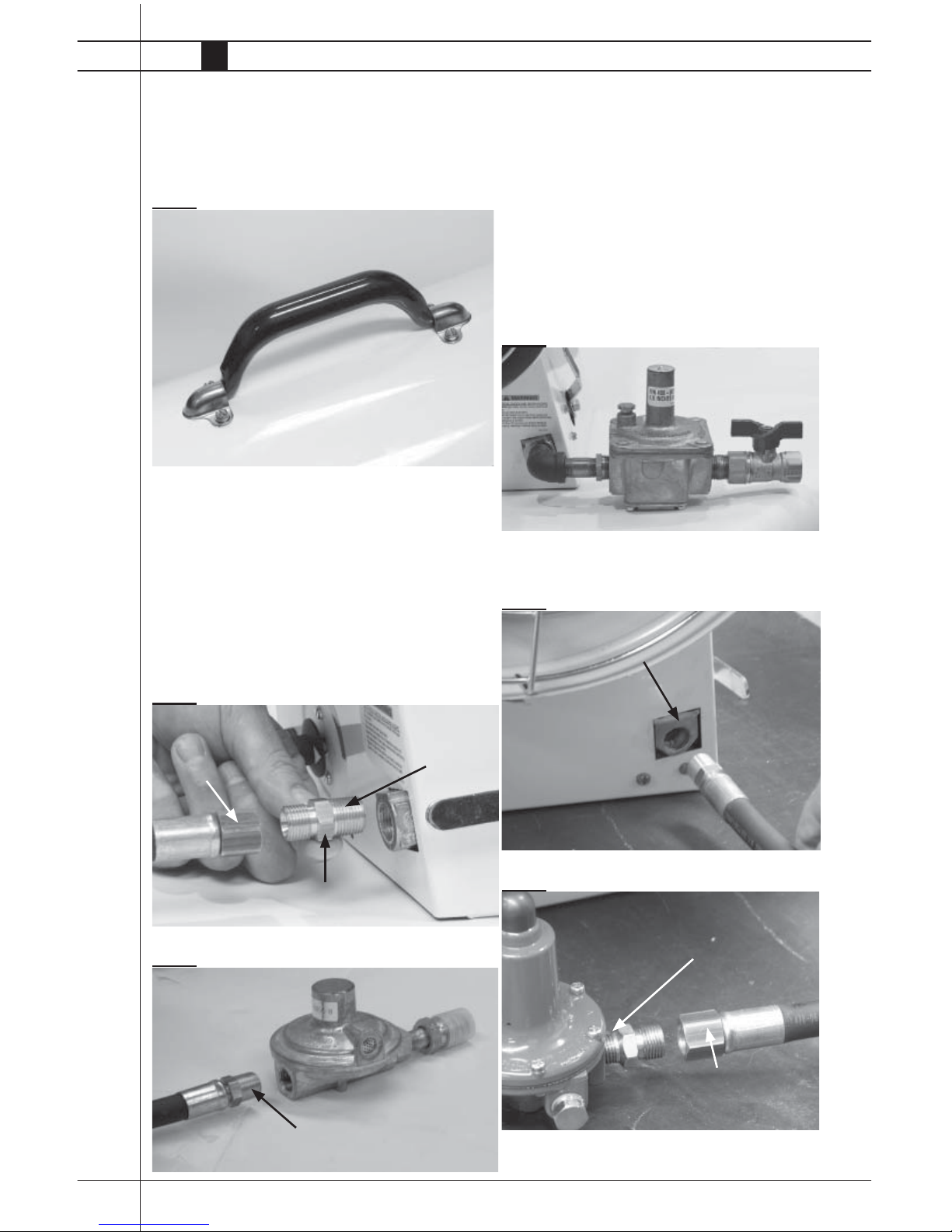
Assemble handle to four holes at barrel top as shown in
Fig. 1. Tighten screws securely.
FIG. 1
Hose and Regulator
Assembly
-- Use pipe thread compound at areas as shown and
ensure all connections are tightened securely.
TRADESMAN 170 Propane Gas
(See Fig. 2 and 3)
FIG. 2
FIG. 3
Handle Assembly
THREAD SWIVEL NUT
END OF HOSE TO
HOSE THREADS ON
ADAPTER
THREAD HOSE ADAPTER TO
INLET OF GAS CONTROL VALVE
APPLY COMPOUND
AT 3/8 INCH THREADS
OF HOSE ADAPTER
APPLY COMPOUND AND THREAD RIGID HOSE
END INTO REGULATOR OUTLET.
-- Apply pipe thread compound at all threaded
connections.
-- Observe gas fl ow direction of regulator.
TRADESMAN 170 NATURAL GAS
-- Apply pipe thread compound at threaded connections
and connect the components together. See Fig. 4 and
tighten securely.
FIG. 4
TRADESMAN 400 (See Fig. 5 and 6)
FIG. 5
FIG. 6
APPLY COMPOUND AND THREAD RIGID
HOSE END INTO GAS INLET AT HEATER
APPLY COMPOUND AT 1/4 INCH
THREADS OF HOSE ADAPTER AND
THREAD INTO REGULATOR OUTLETS
THREAD SWIVEL NUT
END OF HOSE TO HOSE
THREADS ON ADAPTER
Tradesman Construction Heaters
Owner’s Manual • Tradesman
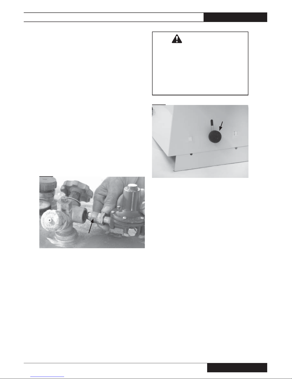
13
1. At the inlet of the regulator is a male nut and stem
called a POL. Remove the cap from the POL but do not
discard it. Insert POL stem into the valve on the propane
fuel container. Thread the nut counterclockwise into
the container’s valve. Tighten the nut securely with a
wrench. See Fig. 7.
2. Slowly open the tank or cylinder valve. This will prevent
lock-up of the excess fl ow valve within POL stem.
3. Check all connections with approved leak detector. Do
not use fl ame to check for leaks. A fi re or explosion may
result.
4. When storing or transporting the heater, ensure the cap
is pushed back onto the POL fi tting to protect the fi tting
from damage and prevent entry of dirt.
FIG. 7
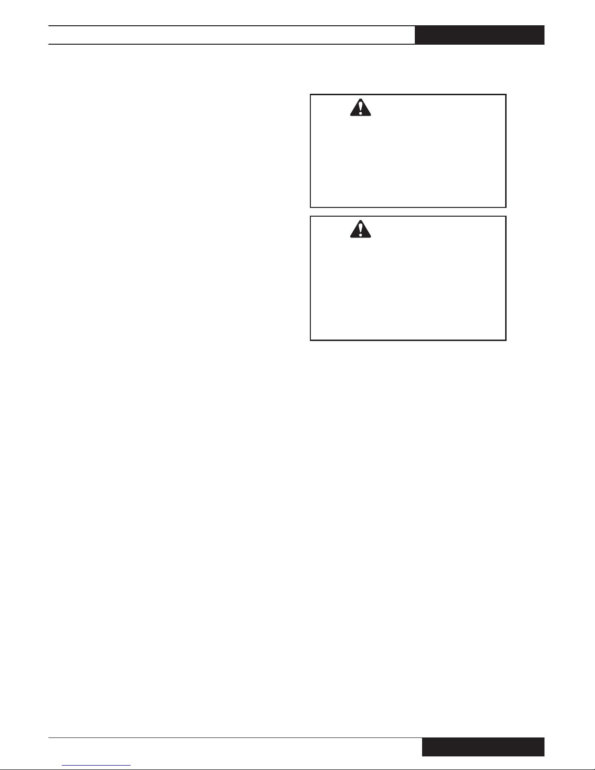
Height Adjustment
Tradesman 170
Tradesman 170 heaters include a height adjustment
feature, allowing the user to change the elevation of the
heater for greater heat direction. See Fig. 8 for location of
adjustment on front base of heater.
To adjust the heater’s discharge outlet height:
-- Loosen knob
-- Lift heater slightly at blower outlet end
-- Pull leg to desired setting
-- Tighten knob.
Connecting Propane
Regulator to Propane
Gas Supply
POL NUT
AND STEM
WARNING
Burn Hazard
■ Do not adjust height while heater is operating
or hot.
■ Adjust height only after the heater has been
disconnected from its power supply and cool
to touch.
■ Failure to follow this warning will result in
burns causing injury.
FIG. 8
KNOB
LEG
Tradesman Construction Heaters
www.lbwhite.com
Owner’s Manual • Tradesman
14
Shut-Down Instructions
Cleaning Instructions
If the heater is to be shut down for cleaning,
maintenance, or repair, follow steps 1-4. Otherwise
turn the thermostat to a lower setting.
1. Close the gas supply valve.
2. Allow the heater to burn off any fuel gas remaining in
the gas supply line.
3. Set the thermostat to its lowest setting.
4. Disconnect the heater from its gas and electrical
supplies.
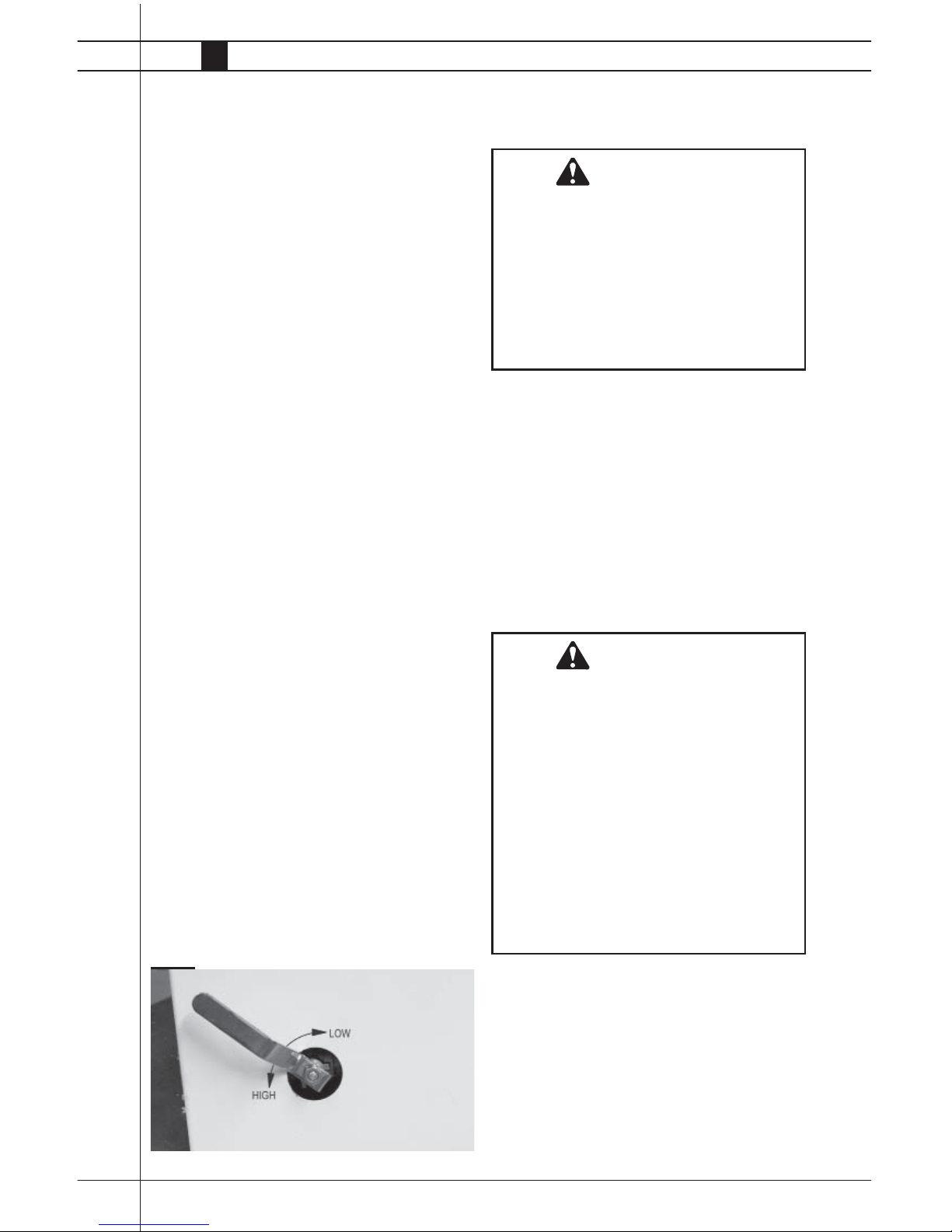
Variable Rate Valve
This heater includes a variable rate valve for adjusting
the heat output from low to high heat, or anywhere
in-between. See Fig. 9.
FIG. 9
1. Before cleaning, shut off all gas supply valves and
disconnect electrical supply.
2. The heater should have dirt or dust removed
periodically:
NOTE: Before each use clean the heater using compressed air or a soft brush or dry rag on its case and
internal components. At this time, dust off the motor case
to prevent the motor from over-heating. Also ensure the
fan blade is free of material build-up.
WARNING
Fire, Burn and Explosion Hazard
■ This heater contains electrical and mechanical components in the gas management, and
safety systems.
■ Such components may become inoperative
or fail due to dust, dirt, wear and aging.
■ Periodic cleaning and inspection as well as
proper maintenance are essential to avoid
serious injury or property damage.
WARNING
Do not use a pressure washer, water, or liquid
cleaning solution on any gas controls. Use of
a pressure washer, water, or liquid cleaning
solution on the control components can cause
severe personal injury or property damage due
to water and/or liquids:
■ In electrical components, and wires causing
electrical shock or equipment failure.
■ On gas control valves causing corrosion
which can result in gas leaks and fi re or
explosion from the leak.
■ Clean all components of the heater with pressurized air, a dry brush, or a dry cloth.
Start-Up Instructions
1. Connect the heater’s electrical cord to an
approved electrical outlet.
2. Open the gas supply valve. For LP heaters, this is
located on the tank or cylinder.
3. Set thermostat on heater to a setting above room
temperature. The heater will start and the burner
will ignite.
■ It is normal for air to be trapped in gas hose on
new installations. You may need to recycle the
heater before air is fi nally purged from the line and
ignition takes place.
4. Do not exceed input rating provided on dataplate
or manufacturer’s recommended burner manifold
pressure for size orifi ce used. Ensure that the pri-
mary air supply to heater is open and free of dust,
dirt and debris for complete proper combustion
Tradesman Construction Heaters
Owner’s Manual • Tradesman
15
Maintenance Instructions Service Instructions
BEFORE EACH USE:
■ Check the area surrounding the heater to ensure it is
clear and free of combustible materials, gasoline, and
other fl ammable vapors and liquids.
■ Have your gas supplier check all gas connections for
leaks or restrictions in gas lines.
■ Inspect the regulator vent to make sure the regulator
vent is not blocked. Debris, insects, insect nests,
snow, or ice on a regulator can block vents and cause
excess pressure at the heater.
■ Check all wiring, associated terminals, and electrical
components within the heater for corrosion, frayed
or cut insulation, tight connections, etc. Repair or
replace as necessary.
■ Check the hose assembly after heater installation, re-
location, and when the heater is in use. If it is evident
there is excessive abrasion or wear, or if the hose is
cut, it must be replaced immediately.
■ Review all heater markings (i.e. wiring diagram, warn-
ings, start-up, shut-down, troubleshooting, etc.) at the
time of maintenance for legibility. Make sure none are
cut, torn, or otherwise damaged. Any damaged markings must be replaced immediately by contacting the
L.B. White Co., Inc. Data plate, startup and shut-down
instructions and warnings are available at no cost.
ANNUALLY:
■ Clean and check the igniter for cracks. Replace if
necessary.
■ Regulators can wear out and function improperly.
Have your gas supplier check the date codes on all
regulators installed and check delivery pressures to
the heater to make sure that the regulator is reliable.
■ Test the auto reset high limit switches to ensure proper
operation. (See Testing instructions for same in this
owner’s manual.)
1. Close the fuel supply valve to the heater and disconnect the electrical supply before servicing unless
necessary for your service procedure.
2. Remove the heater’s bottom base or side panel for
access to electrical components and connections.
3. Disconnect the appropriate electrical leads for the
component being replaced.
4. Remove the fan guard and motor/fan assembly for
access to upper barrel components.
5. The auto reset high limit switches, and thermostat
can be tested by disconnecting the leads at the
component, and placing a jumper connecting the
leads together.:
-- Reconnect the electrical supply and open fuel supply
valves.
-- If the heater lights, the component is defective and
must be replaced.
-- Do not leave the jumper on or operate the heater if the
part is defective. Replace the part immediately.
-- An alternate method for checking the components is to
perform a continuity check.
6. The air proving switch must not be jumpered. If
jumpered, the ignition control will not allow heater
operation. Test the air proving switch for continuity. If
defective, replace the switch
WARNING
Burn Hazard
■ Some heater surfaces are hot for a period of
time after the heater has been shut down.
■ Allow the heater to cool before performing
service, maintenance, or cleaning.
■ Failure to follow this warning will result in
burns causing injury.
WARNING
Fire and Explosion Hazard
■ Do not disassemble or attempt to repair any
heater components or gas train components.
■ All component parts must be replaced if
defects are found.
■ Failure to follow this warning will result in
fi re or explosions, causing property damage,
injury, or death.
Tradesman Construction Heaters
www.lbwhite.com
Owner’s Manual • Tradesman
16
7. For reassembly, reverse the respective service
procedure. Ensure gas connections are tightened
securely.
8. After servicing, start the heater to ensure proper
operation and check for gas leaks.
9. Clean the heater’s orifi ce with compressed air or a
soft, dry rag. Do not use fi les, drills, broaches, etc.
to clean the orifi ce. Doing so may enlarge the hole,
causing combustion or ignition problems. Replace
the orifi ce if it cannot be cleaned properly.
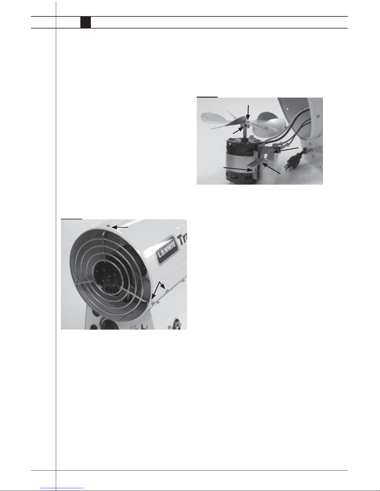
Motor, Fan, and Air
Proving Switch
1. Remove fan guard and screws securing the motor
mount to the heater’s barrel. See Fig 10.
2. Lift motor/fan assembly from heater.
FIG. 10
Motor
-- Remove both screws and strap securing the motor.
-- Position the motor between motor mount stops
when reinstalling.
Air Proving Switch (See Fig. 11)
(Not provided on Tradesman 170 standard heater)
-- Remove screw securing switch bracket to motor
mount.
-- On reassembly, ensure tab on switch bracket is
located in hole.
NOTE: The air proving switch contacts must be open
prior to motor start-up. If the switch contacts
do not close after the motor starts, or are
closed prior to motor starting, the igniter will
not spark nor will the gas control valve open.
REMOVE
REMOVE
(BOTH SIDES)
Fan
-- Loosen set screw at hub.
-- Pull fan from shaft.
-- Ensure fan is fl ush on shaft end, and set screw is
positioned over fl at of motor shaft before tighten-
ing.
FIG. 11
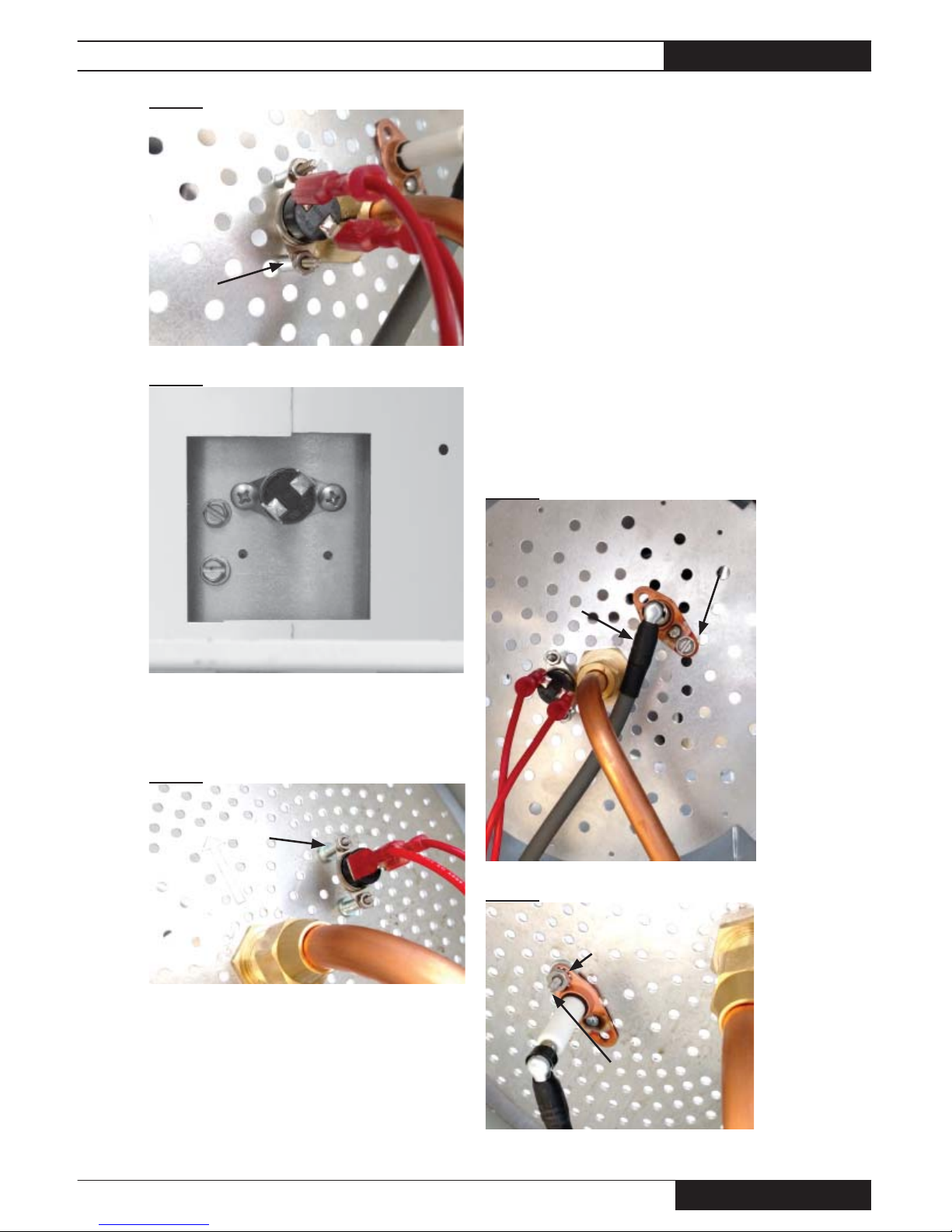
Auto Reset High Limit
Switches
The auto reset high limit switch is designed to cut off
power to the gas control valve if the heater should
overheat due to blockage at the air inlet or discharge
outlet.
Depending on heater model, there can be one or
two high limit heat switches. All Tradesman 170
heaters have two limits. Tradesman 400
heaters have only one limit switch.
Regardless of model, ensure any mounting hardware
(screws, spacers, or washers) is installed when
replacing or testing the switch.
Locations of the limits are:
Tradesman 170:
■ One on the burner plate and one on the underside
of the combustion chamber. See Figs. 12 and 13.
■ The switch on the underside of the combustion
chamber is accessed by removing the base bottom
of the heater.
- The combustion chamber is stamped with the let-
ters P (Propane) or N (Natural Gas) adjacent to the
screw holes to identify location for the appropriate
gas being used.
FAN HUB FLUSH WITH SHAFT END
SET SCREW
REMOVE
SCREWS
AIR PROVING
SWITCH
TAB IN HOLE
STRAP
Tradesman Construction Heaters
Owner’s Manual • Tradesman
17
FIG. 12
FIG. 13
■ Tradesman 400: Limit switch located on burner
plate. See Fig. 14.
FIG. 14
TESTING
The switches should be tested annually.
1. Remove the appropriate switch. Apply a small,soft
fl ame to the sensing disk of the switch. Be careful not
to melt the switch’s plastic housing when conducting
this test.
2. Within a short time, you should hear the contacts of the
switch opening. Check for continuity across terminals
to ensure the switch has opened.
3. Allow the switch to cool. The switch contacts will
close. Check for electrical continuity across the switch
terminals to ensure contacts have closed.
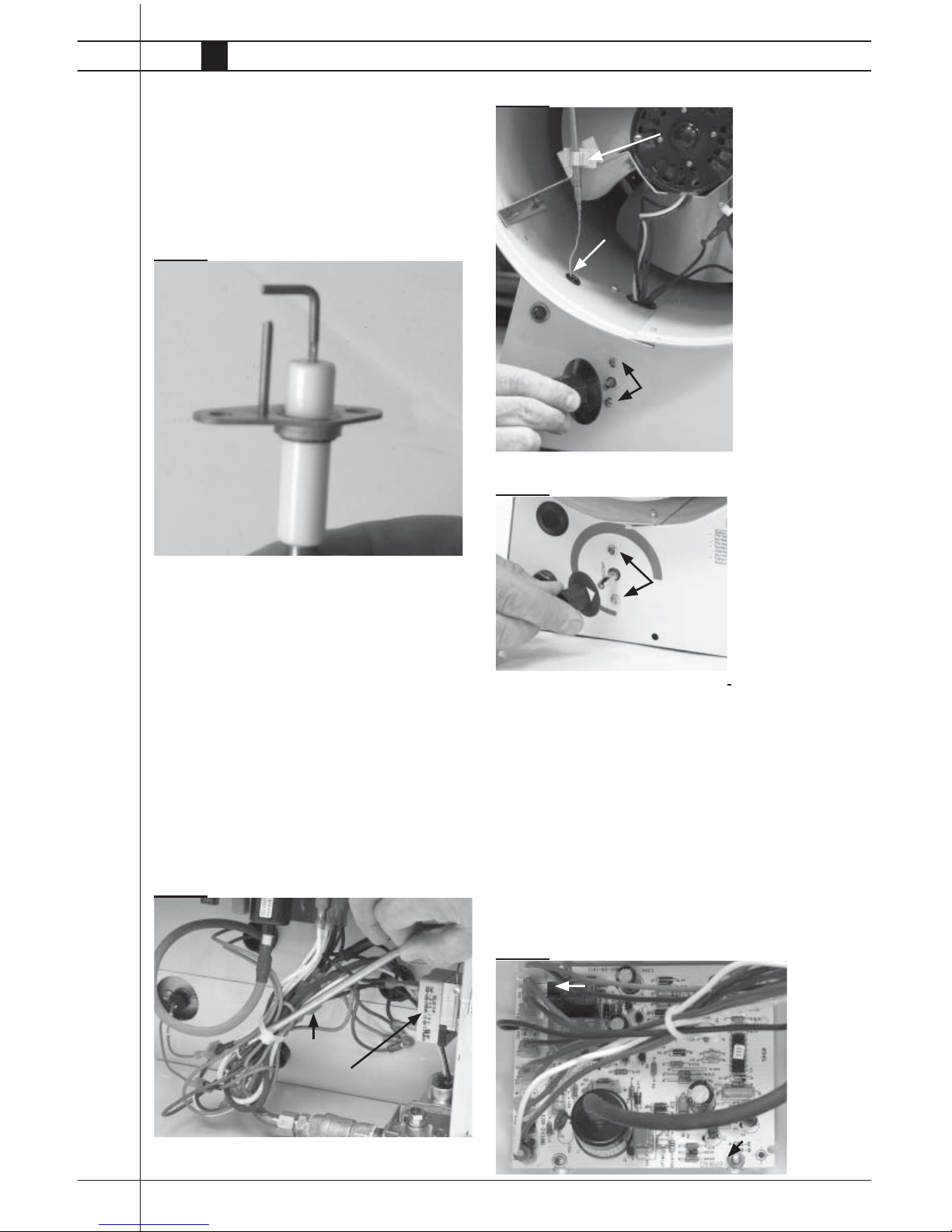
Igniter
■ Regardless of model, disconnect the ignition cable from
the ignitor. See Fig. 15, Tradesman 170 shown.
a. Tradesman 170 heaters:
-- Remove the screw from the ignitor bracket. See Fig.
15
b. Tradesman 400 heaters:
-- Remove the igniter mounting screw, nut, and washer.
See Fig. 16.
FIG. 15
FIG. 16
1 EACH SPACER AND
NUT PER MOUNTING
SCREW
HEIGHT ADJUSTMENT LEG
1 EACH
SP ACER AND
NUT , AND 3
WASHERS PER
MOUNTING
SCREW
P
N
MOUNTING
SCREW
IGNITION
CABLE
WASHER MUST BE LOCATED
BETWEEN IGNITER AND
BURNER PLATE
MOUNTING
SCREW, NUT,
AND WASHER
Tradesman Construction Heaters
www.lbwhite.com
Owner’s Manual • Tradesman
18
MAINTENANCE
1. Using a small wire brush, reach down the barrel of
the heater and brush the igniter electrode. Ensure
buildup is removed.
2. Verify igniter gap of the igniter electrode. Gap
should be 3/16 in. See Fig. 17.
FIG. 17
Thermostat
Tradesman 170:
■ Remove the base bottom. Slide the thermostat
bulb through the cable tie. See Fig. 18.
Tradesman 400:
■ Remove a side panel and the fan guard. Open the
bulb rention clip to remove thermostat bulb. See
Fig. 19. Guide the thermostat bulb through the
bushing.
2. Remove knob and thermostat mounting screws
and disconnect its wiring. See Fig. 20.
FIG. 18
FIG. 19
FIG. 20
Ignition Control
1. Disconnect the LED wire harness (if applicable) from
the circuit board.
2. Disconnect the ignition cable and remove the nuts
securing the control to the side of the heater’s base.
See Fig. 21.
3. When replacing, use care to prevent damage to the
controller’s components.
FIG. 21
CLIP
BUSHING
SCREWS
SCREWS
IGNITION CABLE
NUT
LED WIRE
HARNESS
3/16 IN. / 4.7 MM
BULB
THERMOSTAT
Tradesman Construction Heaters
Owner’s Manual • Tradesman
19
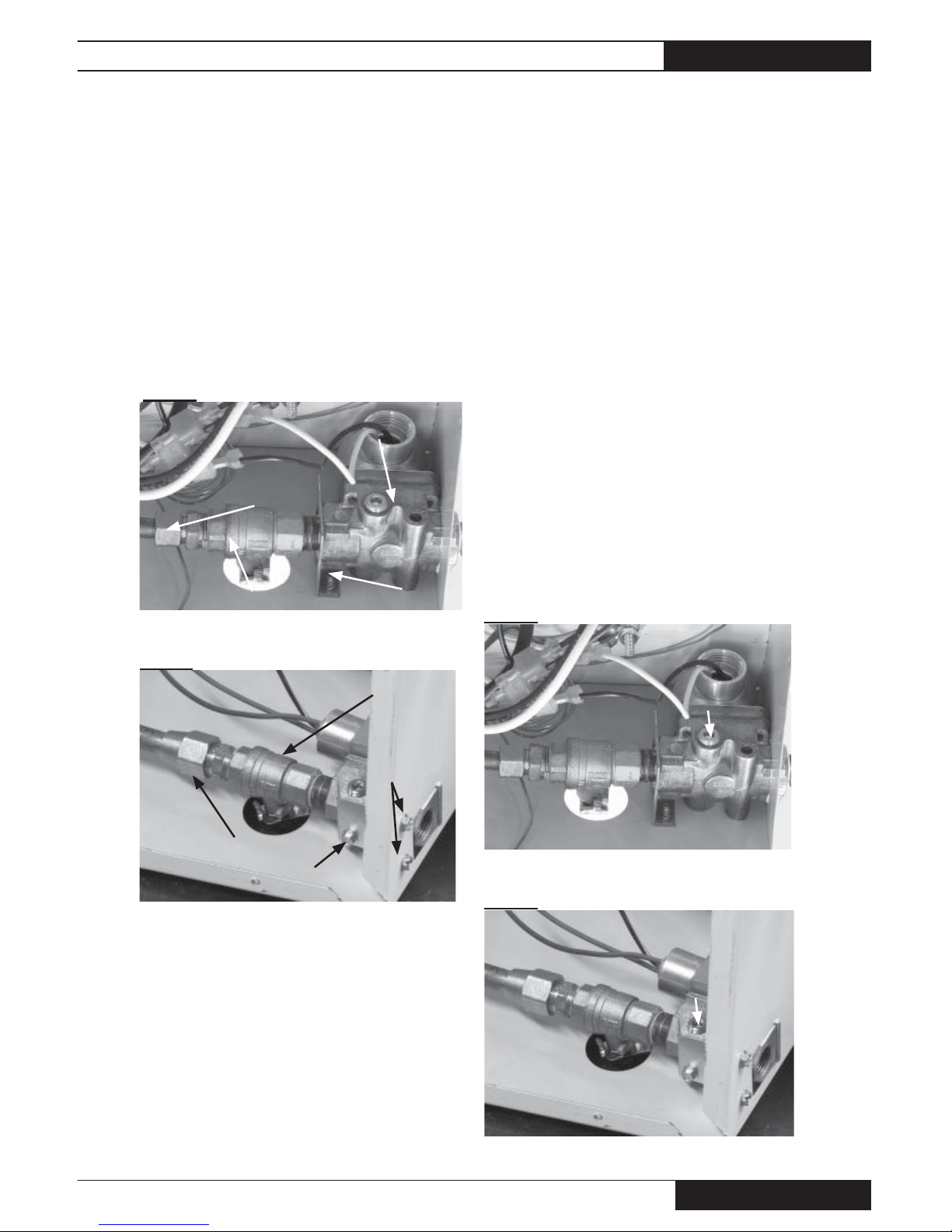
Variable Rate Valve and
Gas Control Valve
1. Loosen the compression nut at the outlet of the
variable rate valve. See Figs. 22 or 23 depending on
heater model.
2. Remove the screws securing the valve bracket to the
heater.
3. Remove the valve assembly from the heater and
replace components as needed.
TRADESMAN 170
FIG. 22
TRADESMAN 400
FIG. 23
Gas Pressure Checks
The following explains a typical procedure to be followed
in checking gas pressures. The gas pressures will vary
depending upon fuel type.
Consult the dataplate on the heater or page 4 in this
manual for specifi c pressures to be used in conjunction
with this procedure. Gas pressure measured at the gas
control valve will verify proper inlet and burner manifold
pressures.
A. Preparation
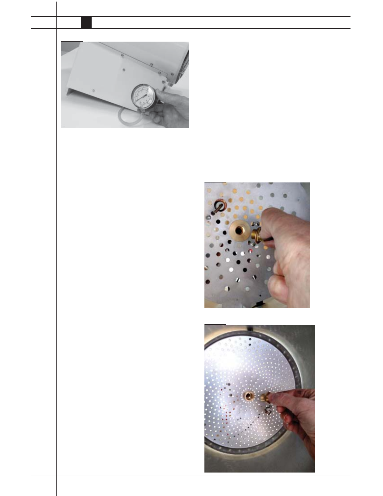
Tradesman 170 heaters:
■ Obtain a pressure gauge capable of reading up to
35 in. W.C.
Tradesman 400 heaters:
■ Obtain a pressure gauge capable of reading up to
10 PSIG.
2. Disconnect the heater from the electrical supply and
close the fuel supply valve to the heater inlet.
3. Remove case panels or base as necessary for access
to the gas control valve.
4. Brush or blow off any dust and dirt on or in the vicinity
of the gas control valve.
B. Gauge Installation
1. Using a 3/16 in. allen wrench, remove the pressure tap
plug on the gas control valve and install the appropriate
gauge. See Figs. 24, 25, and 26. (Ensure gauge tube
is not pinched).
TRADESMAN 170
FIG. 24
TRADESMAN 400
FIG. 25
GAS CONTROL VALVE
COMPRESSION NUT
VARIABLE RATE VALVE SCREWS
COMPRESSION NUT
GAS CONTROL VALVE
VARIABLE RATE VALVE
SCREWS
PLUG
PLUG
Tradesman Construction Heaters
www.lbwhite.com
Owner’s Manual • Tradesman
20
FIG. 26
C. Reading Pressures
1. With the heater operating, the pressure gauge must
read the pressures specifi ed on the dataplate
2. Does the reading at the gas control valve agree with that
specifi ed on the dataplate? If so, then no further check-
ing or adjustment is required. Proceed to section D.
3. If the inlet pressures do not agree with that specifi ed on
the dataplate, then the regulator controlling gas pressure to the heater requires adjustment.
D. Completion
1. Once the proper pressure has been confi rmed and/
or properly set, close the fuel supply to the heater and
allow the heater to burn off any gas remaining in the gas
supply line.
2. Disconnect the heater from its electrical supply.
3. Remove the gauge.
4. Install pressure tap plug and tighten securely
5. Open the fuel supply and start the heater. Check for
gas leaks at the plug Set heater’s thermostat to desired
temperature.
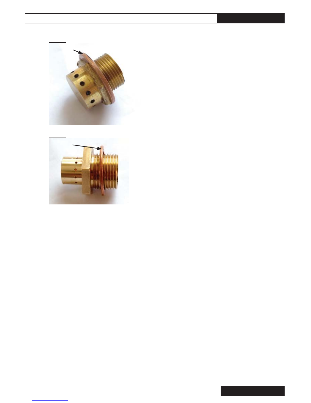
Burner Orifice
Tools Required:
• Ratchet with extensions
• Tradesman 170: 9/16 in. socket
• Tradesman 400: 7/8 in. socket
A. Using the above tools, reach down the barrel of the
heater and loosen the orifi ce from the center of the
burner plate.
B. Remove the orifi ce. See Fig. 27 for Tradesman 170
and Fig. 28 for Tradesman 400.
C. Clean with air or a soft brush.
D. Ensure copper washer is installed onto orifi ce before
threading back into orifi ce holder in burner plate.
E. See Fig. 29 for Tradesman 170 and Fig. 30 for
Tradesman 400.
FIG. 27
FIG. 28
Tradesman Construction Heaters
Owner’s Manual • Tradesman
21
FIG. 29
FIG. 30
COPPER
WASHER
COPPER
WASHER
Tradesman Construction Heaters
www.lbwhite.com
Owner’s Manual • Tradesman
22
Troubleshooting Guide
READ THIS ENTIRE SECTION
BEFORE BEGINNING TO
TROUBLESHOOT PROBLEMS.
The following troubleshooting guide provides
systematic procedures for isolating equipment
problems. THIS GUIDE IS INTENDED
FOR USE BY A QUALIFIED GAS
HEATER SERVICE PERSON. DO NOT
ATTEMPT TO SERVICE THESE HEATERS UNLESS YOU HAVE BEEN
PROPERLY TRAINED.
TEST EQUIPMENT REQUIRED
The following test equipment will be required to
troubleshoot this system with minimal time and
effort.
• Digital Multimeter - for measuring AC voltage
and resistance.
• Pressure Gauge - for checking inlet and pressures at the gas control valve against dataplate
rating.
Ensure all wires and electrical connections are in
good condition before beginning to troubleshoot.
Refer to the system operation sequence in this
section to gain an understanding as to how the
equipment operates during a call for heat. Understanding the sequence of operation is important
as it relates to problem solving.
Heater models labeled Tradesman Ultra have a red light located at the fan
end of the heater. The light will fl ash a spe-
cifi c pattern depending upon the problem which is
diagnosed. If the light is fl ashing, the fl ash pattern
will be followed by a pause and then a repeat of
the fl ash pattern until the problem is corrected.
Use the light to help diagnose the problem.
Heater models labeled Tradesman do
not have the diagnostic red light.
Troubleshooting Flow Charts are provided to eliminate
problems. To use the fl ow charts effectively, you must fi rst
identify the problem.
Tradesman Ultra Diagnostic Heaters
Page
Red light is not on .................................................... 24
Red light is fl ashing:
A. One Time............................................................. 25
B. Two Times ........................................................... 26
C. Three Times ........................................................ 27
D. Four Times .......................................................... 27
D. Five Times........................................................... 27
Tradesman Non Diagnostic Heaters Page
Fan Does Not Run, Heater Does Not Light ............. 28
Fan Runs, Heater Does Not Light ........................... 29
Heater Lights, But Does Not Stay Lit ....................... 30
Tradesman 170 Standard Heaters: Do not
have an air proving switch. Voltage is sent
directly to the gas control valve through
both limit switches.
Components should be replaced only after each step has
been completed and replacement is suggested in the fl ow
chart. Refer to the Servicing sections as necessary to
obtain information on disassembly and replacement procedures of the component once the problem is identifi ed by
the fl ow chart.
DIRECT IGNITION OPERATION SEQUENCE: (HEATERS
WITH AIR PROVING SWITCH)
-- Voltage is sent to the thermostat.
-- Thermostat calls for heat.
-- Thermostat sends voltage to ignition control.
-- Red light is illuminated.( Diagnostic Heaters Only).
-- Ignition control module performs self safety check.
-- Internal components are tested.
-- Ignition control module begins ignition trial sequence.
-- Ignition control module sends 115 volts to air
proving switch.
-- Ignition control sends 115 volts to motor
-- Motor starts.
-- Air proving switch closes and 115 volts are returned to
the ignition control module.
-- Ignition control module sends high voltage to the
igniter electrode.
-- Igniter sparks.
-- Ignition control module sends 115 volts to the gas control
valve through the backfl ash switches.
-- Gas control valve opens.
WARNING
■ This heater can start at any time.
■ Troubleshooting this system may require oper-
ating the unit with voltage present and gas on.
Be careful when working on the heater.
■ Failure to follow this warning may result in
property damage, personal injury or death.

Tradesman Construction Heaters
Owner’s Manual • Tradesman
23
-- Ignition occurs.
-- Igniter continues to spark until fl ame proving occurs.
-- Ignition spark is cut off.
-- Gas valve stays open.
-- Room warms to desired temperature.
-- Thermostat is satisfi ed.
-- Heater shuts down.
-- Process starts again on a call for heat.
IGNITION FAILURE SEQUENCE:
-- Trial for ignition takes approximately 10 seconds.
-- If ignition module does not sense a fl ame within the
ignition trial, the module goes into safety lockout (3
fl ash pattern.)
-- Gas valve closes.
-- Ignition spark shuts off.
-- Fan motor stops. (See note below).
-- To retry for ignition, the systems must be reset:
-- Turn the thermostat down and then up to call for heat
or unplug heater and plug it back in or
NOTE: Tradesman 170 Standard Heaters:
If ignition failure occurs, the fan
motor continues to operate.
Tradesman Construction Heaters
www.lbwhite.com
Owner’s Manual • Tradesman
24
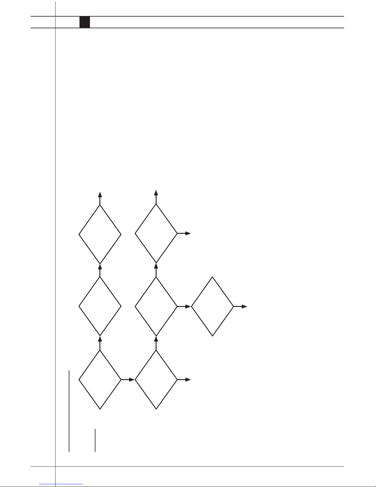
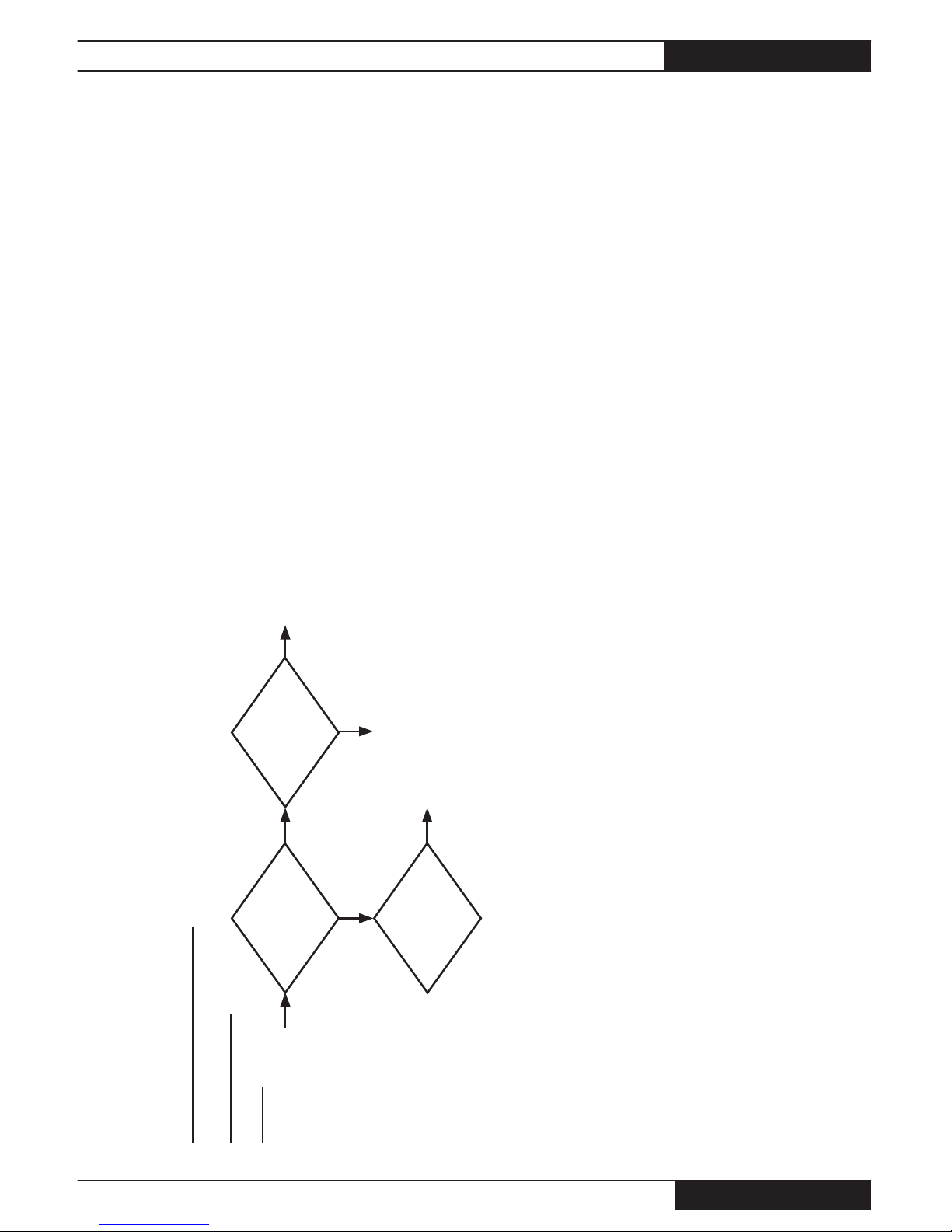
Proble m
Red light not on
TRADESMAN ULTRA HEATER
Does fan motor run?
Is thermostat set above
room temperature?
Does thermostat
receive proper voltage
from power cord?
Is proper voltage
supplied to heater
power cord?
Check extension cords and circuit
breakers. Repair extension cord,
reset breaker, or call
qualifi ed electrician.
Does thermostat send
proper voltage to
ignition control?
Defective ignition
control
Set thermostat above
room temperature.
Check for proper
voltage delivered from
thermostat to circuit
board. If electrical
connections are good,
replace thmerostat.
Does heater light? LED light defective Replace LED
No
No No
No
No
Yes
Yes Yes Yes
Yes Yes
Tradesman Construction Heaters
Owner’s Manual • Tradesman
25
Red Light Flashing
One Time
Air Proving Switch
contacts are closed
before fan motor star ts.
TRADESMAN ULTRA HEATERS
Is air proving sw tich
stuck closed? Check
continuity.
Is air proving sw tich
shorted?
Is air proving sw tich
binding?
Replace air proving swtich.
Check continuity on air
proving swtich in open and
closed positions. Replace
the swtich if necessary.
Repair.
No No
Yes
Yes
Yes
Tradesman Construction Heaters
www.lbwhite.com
Owner’s Manual • Tradesman
26
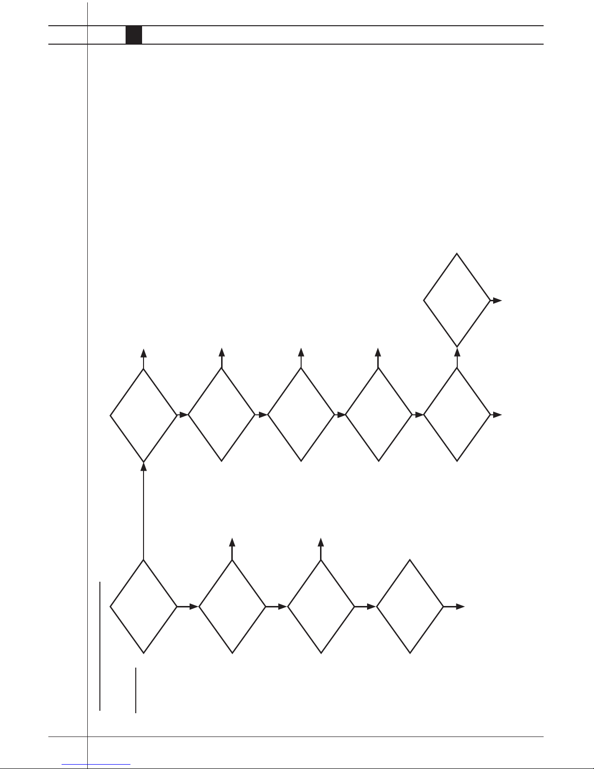
Two Times
Indicates lack of
air proving in fan
section (Flash pat-
tern begins within
90 seconds after
condition occurs)
TRADESMAN ULTRA HEATER
Does fan motor run?
Is ignition control
receiving proper
voltage?
Is proper voltage sup-
plied to heater power
cord?
Check circuit breakers, and any
extension cords if used. Contact
a qualifi ed electrician.
Is proper voltage
supplied to motor from
ignition control?
Defective motor.
Defective ignition
control.
Are there blockages at
air inlet of heater?
Is fan binding, or bent,
or caked with dir t?
Is fan loose on motor
shaft?
Is switch binding?
Do air proving switch
contacts close? Check
continuity.
Does ignition control
send voltage to air
proving swtich?
Defective air proving switch. Defective ignition control
Remove blockage.
Remove dirt. Repair
or replace fan.
Tighten fan blade set
screw
Repair.
No
No
No
No
No
No
No
No
No No
Yes
Yes
Yes
Yes
Yes
Yes
Yes
Yes
Tradesman Construction Heaters
Owner’s Manual • Tradesman
27
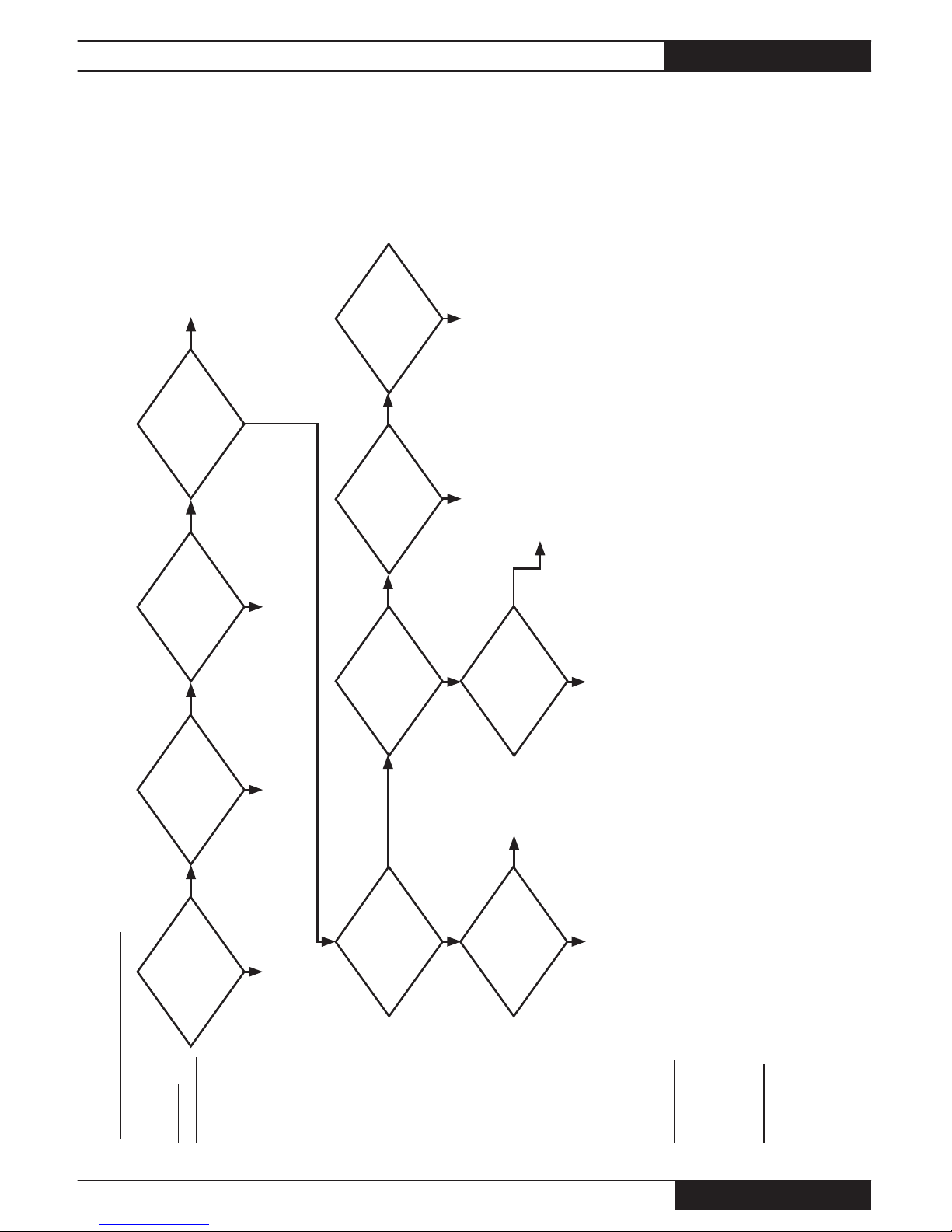
Proble m
Three Times
Indicates ignition
failure. The ignition
control is in safety
lockout.
Four Times: If control module does not reset, then replace it (Internal board fault).
If module resets, then have qualifi ed electrician check power source
for power quality problems. (Frequency, line noise, line spikes, loose
connections, too small wire gauge.
Five Times: Flame sense related problems. Check for cracked or dirty
igniter, improperly positioned sensor, or poor fl ame igniter
ground.
TRADESMAN ULTRA HEATER
Is the heater properly
grounded?
Does gas solenoid
valve open?
Does igniter spark?
Is igniter high voltage
lead securely connected?
Connect high
voltage lead
Is igniter properly
gapped?
Check igniter gap.
Regap to 3/16 in.
Determine if ignitor receives high voltage:
- CLOSE THE HEATER’S FUEL SUPPLY VALVE
- Disconnect ignition lead from ignition control.
- Position a screwdriver tip about 3/16 in. / 4.7 mm away from ignition
control where lead was connected.
- Start the heater
- If no spark is seen, replace the ignition control.
- If spark is seen, reconnect ignition lead to control.
- Disconnect the lead at the ignitor
- Hold the lead about 3/16 in. / 4.7 mm from a grounded section of the heater.
- Start the heater.
- If no spark is observed, replace the ignition lead.
- If spark is observed, replace the ignitor.
Reposition igniter. (See
service instructions).
Is igniter gap posi-
tioned toward burner
orifi ce?
Is proper voltage
supplied to gas valve?
Defective
gas valve.
Defective wires or connections.
If good, replace ignition control.
Is proper fuel supplied
to heater inlet?
Is proper gas pressure
supplied to heater?
Is high limit heat
switch tripped? Check
continuity.
If switch is tripped, determine
cause. Check for obstruction
at discharge outlet or air inlet
of heater, and low voltage from
power supply.
Ensure all grounds are
connected.
Connect proper gas
supply to heater. Open
all gas shutoff valves.
Provide proper gas supply pressure
to heater. Refer to dataplate. If LP
gas is used, ensure container is full.
No
No
No
No No
No No
No
No
No
Yes
Yes
Yes Yes
Yes
Yes
Yes Yes Yes
Tradesman Construction Heaters
www.lbwhite.com
Owner’s Manual • Tradesman
28
Proble m
Fan motor does
not run, heater
does not light.
TRADESMAN STANDARD HEATER (NO RED DIAGNOSTIC LIGHT)
ALL TRADESMAN 400
STANDARD HEATERS
Is proper voltage
supplied to heaters?
Is voltage supplied to
air proving switch from
the ignition control?
Is thermostat set above
room temperature?
Are air proving switch
contacts stuck closed?
Check continuity. If the switch
is binding, repair as needed,
other wise replace the swtich.
Is proper voltage sup-
plied to thermostat?
Is proper voltage
supplied to ignition
control?
Does the motor start?
Provide proper voltage to heater.
Check breaker and extension
cords.
Defective ignition control.
Set thermostat above room
temperature.
Check power cord and
electrical supply.
Defective thermostat. Check for voltage from ignition control to
fan motor. If motor receives voltage but
does not start, ensure fan blade is not
jammed, or replace the motor.
No
No
No No No No
Yes
Yes
Yes
Yes
Yes Yes Yes
Tradesman Construction Heaters
Owner’s Manual • Tradesman
29
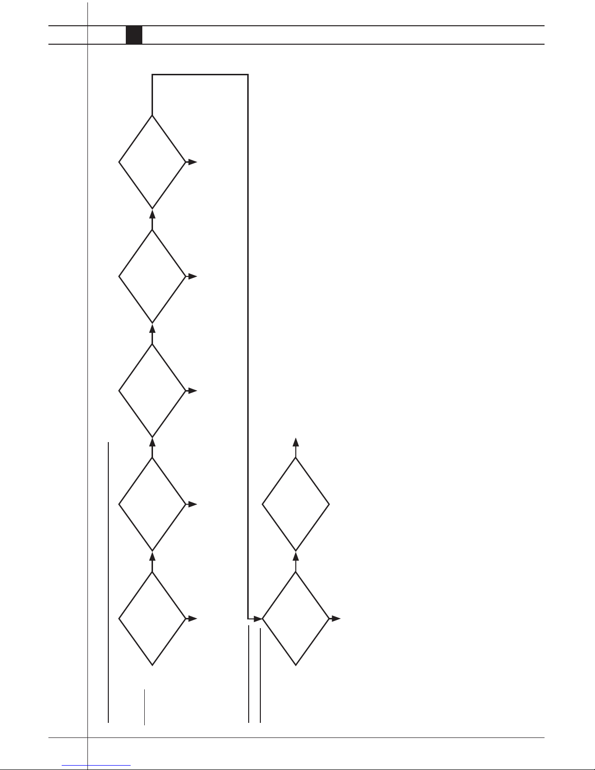
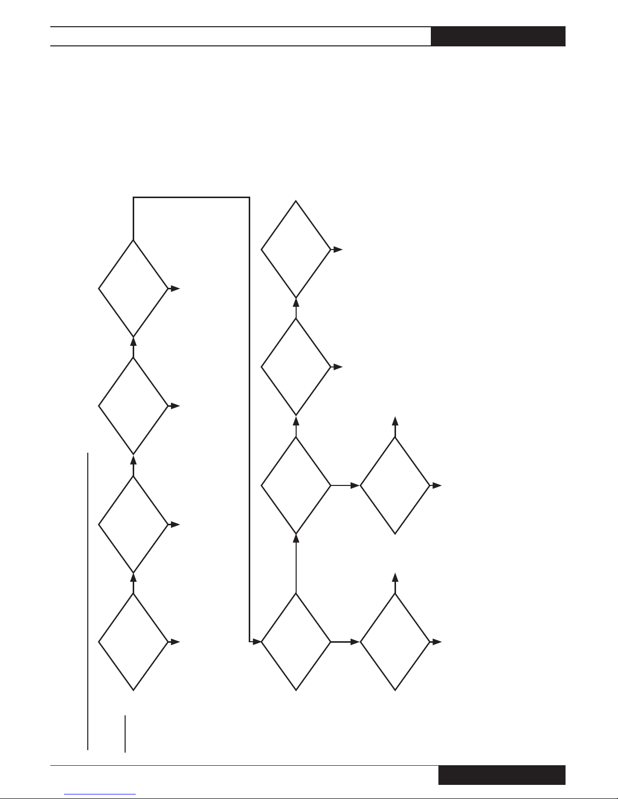
Proble m
Fan runs, heater
does not light.
TRADESMAN STANDARD HEATERS (NO RED DIAGNOSTIC LIGHT)
Are all fuel supply
valves open?
Does gas solenoid
valve open?
Is proper voltage sup-
plied to valve?
Defective
valve
Defective wires or
connections. If wires and
connections are good,
replace ignition control.
Is proper gas pressure
supplied?
Does igniter spark?
Is high voltage lead
securely connected
to ignition control and
ignitor?
Determine if ignitor receives high voltage:
- CLOSE THE HEATER’S FUEL SUPPLY VALVE
- Disconnect ignition lead from ignition control.
- Position a screwdriver tip about 3/16 in. / 4.7 mm away from ignition
control where lead was connected.
- Start the heater
- If no spark is seen, replace the ignition control.
- If spark is seen, reconnect ignition lead to control.
- Disconnect the lead at the ignitor
- Hold the lead about 3/16 in. / 4.7 mm from a grounded section of the heater.
- Start the heater.
- If no spark is observed, replace the ignition lead.
- If spark is observed, replace the ignitor.
Connect high voltage lead
Tradesman 400 heaters,
do air proving switch
contacts close?
Is igniter properly gapped?
Are the auto reset
limit switch contacts
closed?
Is igniter gap posi-
tioned toward burner
orifi ce?
Reposition igniter.
(See Service Instructions)
Check igniter gap. Regap to
3/16 in. / 4.7 mm
Open the fuel supply valves. Provide proper pressure to
heater gas inlet.
Check continuity of swtich.
Ensure swtich arm is not binding.
Repair or replace air proving
switch.
Check continuity across swtich.
If contacts are open determine
cause. Check for: proper voltage,
blockages at air inlets or outlet,
loose fan, or low fan speed. If
good, replace limit switch.
No No
No
No
No
No
No
No
No
No
Yes
Yes
Yes
Yes
Yes
Yes
Yes
Yes
Yes
Tradesman Construction Heaters
www.lbwhite.com
Owner’s Manual • Tradesman
30
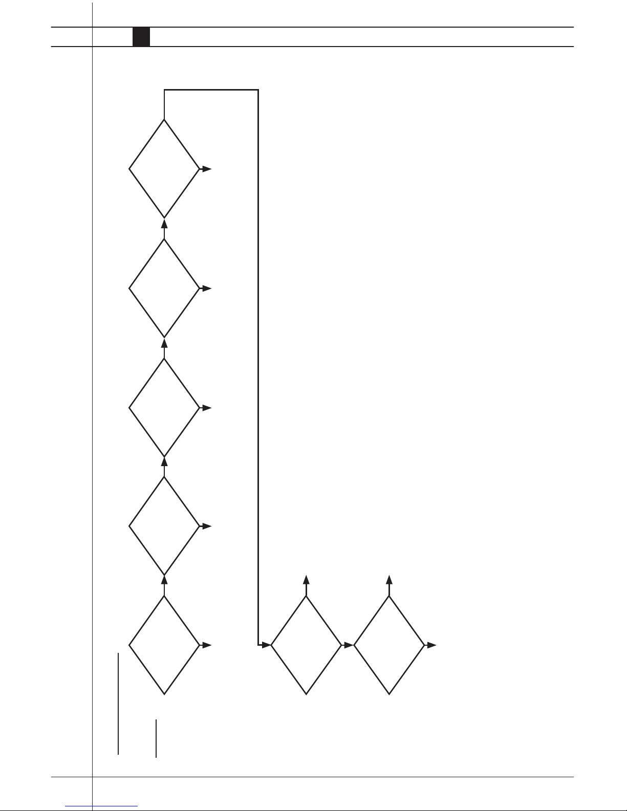
Proble m
Heater lights but
will not stay lit
TRADESMAN HEATER
Is the heater properly
grounded?
Is igniter cracked? Replace igniter.
Defective ignition
control.
Is high voltage lead
securely connected?
Is proper fuel supplied
to heater inlet?
Is proper gas pressure
supplied to heater?
Is proper voltage sup-
plied to heater?
Is igniter clean?
Ensure all grounds are
connected.
Connect high voltage lead?
Connect proper gas supply to
heater. Open all gas shutoff
valves.
Provide proper gas supply
pressure to heater. Refer to
dataplate. If LP gas is used,
ensure LP container is full, and
of proper size.
Check electrical supply. If
extension cords are used, ensure
proper wire gauge.
Clean and check gap. Replace
igniter if needed.
No
No
No
No No No No
Yes
Yes
Yes
Yes Yes Yes Yes
 Loading...