

L.B. White Tradesman CP045CK, Tradesman CP075CK, Tradesman CP125DK, Tradesman CP175DK, Tradesman CP210DK Owner's Manual And Instructions
...
Owner's Manual and Instructions
Tradesman Kerosene Heaters
MODELS OUTPUT (BTUH) FUEL
CP045CK
CP075CK
CP125DK
CP175DK
CP210DK
Certification by:
45,000
75,000
125,000
175,000
210,000
1-K
Kerosene
Congratulations!
You have purchasedthe finest kerosene portable forcedair construction heater available.
Your new L.B. White heater incorporates the benefits from the most experienced
manufacturer of heating products using state-of-the-art technology.
We, at L.B. White, thank you for your confidence in our products and welcome any
suggestions or comments you may have...call us, toll-free, at (800) 345-7200.
ATTENTION ALL USERS
This heater has been tested and evaluated by C.S.A. International in accordance with
the requirements of Standard UL733 and ANSI A10.10-1998, CAN/CSA B140.0-03
and CSA B140.8 - 1967 and is listed and approved as a Kerosene forced-air
construction heater with application for the temporary heating of buildings under
construction, alteration, or repair. If you are considering using this product for any
application other than its intended use, then please contact the L.B. White Co., Inc.
150-28814
GENERAL HAZARD WARNING
- Failure to comply with the precautions and instructions provided with this heater, can result in:
— Death
— Serious bodily injury or burns
— Property damage or loss from fire or explosion
— Asphyxiation due to lack of adequate air supply or carbon monoxide poisoning
— Electrical shock
- Read this Owner’s M anual before installing or using this product.
- Only properly-trained service people should repair or install this heater.
- Save this Owner’s Ma
nual for future use and reference.
- Owner’s Manuals and replacement labels are available at no charge. For assistance, contact L.B. White at 800-
345-7200.
WARNING
Fire and Explosion Hazard
- Not for home or recreational vehicle use.
- Installation of this heater in a home or recreational
vehicle may result in a fire or explosion.
- Fire or explosions can cause property damage or loss
of life.
Fire and Explosion Hazard
- Keep solid combustibles a safe distance away from
the heater.
- Solid combustibles include wood, paper, or plastic
products, building materials and dust.
- Do not use the heater in spaces which contain or may
WARNING
contain volatile or airborne combustibles.
FOR YOUR SAFETY
Do not store or use gasoline or other flammable vapors
and liquids in the vicinity of this or any other appliance.
- Volatile or airborne combustibles include gasoline,
solvents, paint thinner, dust particles or unknown
chemicals.
- Failure to follow these instructions may result in a fire
or explos
ion.
- Fire or explosions can lead to property damage,
personal injury or loss of life.
2

Table of Contents
SECTION PAGE
General Information . . . . . . . . . . . . . . . . . . . . . . . . . . . . . . . . . . . . . . . . . . . . . . . . . . . . . . . . . . . . . . . . . . .3
Heater Specifications . . . . . . . . . . . . . . . . . . . . . . . . . . . . . . . . . . . . . . . . . . . . . . . . . . . . . . . . . . . . . . . . . .4
Safety Information
Hazard Definitions . . . . . . . . . . . . . . . . . . . . . . . . . . . . . . . . . . . . . . . . . . . . . . . . . . . . . . . . . . . . . . . . .6
General Safety Information . . . . . . . . . . . . . . . . . . . . . . . . . . . . . . . . . . . . . . . . . . . . . . . . . . . . . . . . .6
Installation & Assembly
Heater Specifications . . . . . . . . . . . . . . . . . . . . . . . . . . . . . . . . . . . . . . . . . . . . . . . . . . . . . . . . . . . . . .8
Assembly . . . . . . . . . . . . . . . . . . . . . . . . . . . . . . . . . . . . . . . . . . . . . . . . . . . . . . . . . . . . . . . . . . . . . . . .9
Operation
Overview of Heater Design . . . . . . . . . . . . . . . . . . . . . . . . . . . . . . . . . . . . . . . . . . . . . . . . . . . . . . . . . 10
The Safety System . . . . . . . . . . . . . . . . . . . . . . . . . . . . . . . . . . . . . . . . . . . . . . . . . . . . . . . . . . . . . . . . 10
Fuel Specifications . . . . . . . . . . . . . . . . . . . . . . . . . . . . . . . . . . . . . . . . . . . . . . . . . . . . . . . . . . . . . . . 10
Fueling Your Heater . . . . . . . . . . . . . . . . . . . . . . . . . . . . . . . . . . . . . . . . . . . . . . . . . . . . . . . . . . . . . . .11
To Start Heater . . . . . . . . . . . . . . . . . . . . . . . . . . . . . . . . . . . . . . . . . . . . . . . . . . . . . . . . . . . . . . . . . .11
To Shutdown Heater . . . . . . . . . . . . . . . . . . . . . . . . . . . . . . . . . . . . . . . . . . . . . . . . . . . . . . . . . . . . . .11
To Restart Heater . . . . . . . . . . . . . . . . . . . . . . . . . . . . . . . . . . . . . . . . . . . . . . . . . . . . . . . . . . . . . . . .11
Extra Electrical Outlet . . . . . . . . . . . . . . . . . . . . . . . . . . . . . . . . . . . . . . . . . . . . . . . . . . . . . . . . . . . . .11
Longterm Storage of Your Heater . . . . . . . . . . . . . . . . . . . . . . . . . . . . . . . . . . . . . . . . . . . . . . . . . . .12
Maintenance
Fuel Tank . . . . . . . . . . . . . . . . . . . . . . . . . . . . . . . . . . . . . . . . . . . . . . . . . . . . . . . . . . . . . . . . . . . . . . .13
Air Intake Filter . . . . . . . . . . . . . . . . . . . . . . . . . . . . . . . . . . . . . . . . . . . . . . . . . . . . . . . . . . . . . . . . . . .13
Air Output /Lint Filter . . . . . . . . . . . . . . . . . . . . . . . . . . . . . . . . . . . . . . . . . . . . . . . . . . . . . . . . . . . . .13
Fan Blades . . . . . . . . . . . . . . . . . . . . . . . . . . . . . . . . . . . . . . . . . . . . . . . . . . . . . . . . . . . . . . . . . . . . . .13
Nozzle . . . . . . . . . . . . . . . . . . . . . . . . . . . . . . . . . . . . . . . . . . . . . . . . . . . . . . . . . . . . . . . . . . . . . . . . .14
Spark Plug . . . . . . . . . . . . . . . . . . . . . . . . . . . . . . . . . . . . . . . . . . . . . . . . . . . . . . . . . . . . . . . . . . . . . .15
Photocell . . . . . . . . . . . . . . . . . . . . . . . . . . . . . . . . . . . . . . . . . . . . . . . . . . . . . . . . . . . . . . . . . . . . . . .15
Fuel Filter . . . . . . . . . . . . . . . . . . . . . . . . . . . . . . . . . . . . . . . . . . . . . . . . . . . . . . . . . . . . . . . . . . . . . . .16
Pump Pressure Adjustment . . . . . . . . . . . . . . . . . . . . . . . . . . . . . . . . . . . . . . . . . . . . . . . . . . . . . . . .16
Replacing Fuse . . . . . . . . . . . . . . . . . . . . . . . . . . . . . . . . . . . . . . . . . . . . . . . . . . . . . . . . . . . . . . . . . .17
Wiring Diagram . . . . . . . . . . . . . . . . . . . . . . . . . . . . . . . . . . . . . . . . . . . . . . . . . . . . . . . . . . . . . . . . . . . . . .18
Troubleshooting . . . . . . . . . . . . . . . . . . . . . . . . . . . . . . . . . . . . . . . . . . . . . . . . . . . . . . . . . . . . . . . . . . . . .20
Parts Identification
Parts Schematic (CP045CK & CP075CK) . . . . . . . . . . . . . . . . . . . . . . . . . . . . . . . . . . . . . . . . . . . . .21
Parts List (CP045CK & CP075CK) . . . . . . . . . . . . . . . . . . . . . . . . . . . . . . . . . . . . . . . . . . . . . . . . . . .22
Parts Schematic (CP125DK & CP175DK) . . . . . . . . . . . . . . . . . . . . . . . . . . .
Parts List (CP125DK & CP175DK) . . . . . . . . . . . . . . . . . . . . . . . . . . . . . . . . . . . . . . . . . . . . . . . . . . .24
Parts Schematic (CP210DK) . . . . . . . . . . . . . . . . . . . . . . . . . . . . . . . . . . . . . . . . . . . . . . . . . . . . . . .25
Parts List (CP210DK) . . . . . . . . . . . . . . . . . . . . . . . . . . . . . . . . . . . . . . . . . . . . . . . . . . . . . . . . . . . . .26
Parts Schematic (Handles/Wheels) . . . . . . . . . . . . . . . . . . . . . . . . . . . . . . . . . . . . . . . . . . . . . . . . .27
Warranty Information . . . . . . . . . . . . . . . . . . . . . . . . . . . . . . . . . . . . . . . . . . . . . . . . . . . . . . . . . . . . . . . . .28
. . . . . . . . . . . . . . . . . .23
General Information
This Owner's Manual includes all options and accessories
commonly used on this heater.
When calling for technical service assistance, or for other
spec i fic i n f o rmat i o n, al w a y s h ave mode l n umbe r,
configuration number and serial number available. This
information is contained on the dataplate.
This manual will instruct you in the operation and care of
your unit. Have your qualified installer review this manual
with you so that you fully understand the heater and how it
functions.
3
Th e ins talla tion, repa ir, and servi cing of th e hea ter
requires continuing expert training and knowledge of
kerosene heaters and should not be attempted by anyone
who is not so qualified.
Contact your local L.B. White distributor or the L.B. White
Co., Inc. for assistance, or if you have any questions about
the use of the equipment or its application.
The L.B. White Co., Inc. has a policy of continuous product
improvem e n t. It re s er v e s the righ t to chan g e
specifications and design without notice.

Heater Specifications
Model
SPECIFICATIONS CP045CK CP075CK
Fuel Type 1-K, Kerosene
Max Input (BTUH) 45,000 75,000
Ventilation Air Required
to Support Combustion 175 CFM 265 CFM
Pump Pressure (psig) 2.8 3.8
Fuel Consumption per Hour (gal) .35 .57
Motor Characteristics
1/8 HP, 3,300 RPM 1/8 HP, 3120 RPM
Electrical Supply (Voltz/Hz/Phase) 120/60/1
Amp Draw
Dimensions (Inches) Length x width x height 32” x 11 3/4” x 16 3/4”
Minumum Safe
Distances From
Nearest
Combustible
Materials
Net Weight (Lbs.)
Shipping Weight (Lbs.)
Minimum Ambient Temperature
in Which Heater May Be Used
CONTINUOUS
OPERATION
TOP 4 ft.
SIDES 4 ft.
BACK 4 ft.
BLOWER OUTLET 8 ft.
BULK FUEL STORAGE CONTAINER 25 ft.
1.6 1.6
27.6
32.0
Ball Bearing
-20oF
27.6
32.0
4
Heater Specifications
Model
SPECIFICATIONS CP125DK CP175DK CP210DK
Fuel Type
Max Input (BTUH)
Ventilation Air Required to Support Combustion
Pump Pressure (PSIG)
Fuel Consumption per Hour (gal)
Motor Characteristics
Electrical Supply (Voltz/Hz/Phase)
Amp Draw
CONTINUOUS
OPERATION
1-K, Kerosene
125,000 175,000 210,000
520 CFM 600 CFM 650 CFM
5.5 7.5 8.5
.95 1.32 1.6
Ball Bearing
1/5HP 3455 RPM 1/4HP 3430 RPM 1/3HP 3380 RPM
120/60/1
2.5 3.2 3.7
Length x Width x Height
Minumum Safe
Distances From
Nearest
Combustible
Materials
Net Weight (lbs.)
Shipping Weight (lbs.)
Minimum Ambient Temperature
in which Heater may be used
1
36
/10” x 23 x 24 6/10”
Top
Sides
Back
Blower Outlet
Bulk Fuel Storage Container
55.8 62.4 63.9
63.1 71.2 72.8
8
41
/10” x 24 6/10” x 26 1/10”
4 ft.
4 ft.
4 ft.
8 ft.
25 ft.
o
F
-20
5
Safety Information
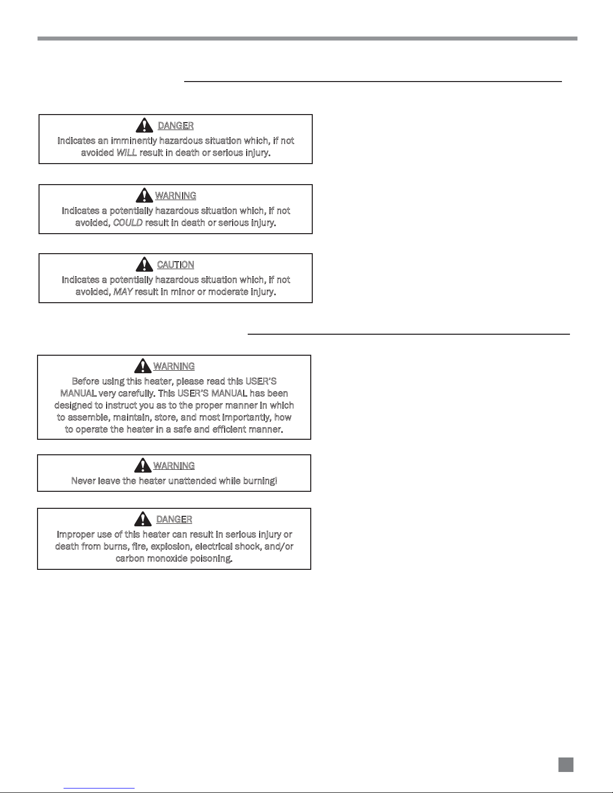
HAZARD DEFINITIONS
DANGER
Indicates an imminently hazardous situation which, if not
avoided WILL result in death or serious injury.
WARNING
Indicates a potentially hazardous situation which, if not
avoided, COULD result in death or serious injury.
CAUTION
Indicates a potentially hazardous situation which, if not
avoided, MAY result in minor or moderate injury.
GENERAL SAFETY INFORMATION
WARNING
Before using this heater, please read this USER’S
MANUAL very carefully. This USER’S MANUAL has been
designed to instruct you as to the proper manner in which
to assemble, maintain, store, and most importantly, how
to operate the heater in a safe and efficient manner.
WARNING
Never leave the heater unattended while burning!
DANGER
Improper use of this heater can result in serious injury or
death from burns, fire, explosion, electrical shock, and/or
carbon monoxide poisoning.
6
GENERAL SAFETY INFORMATION (cont.)
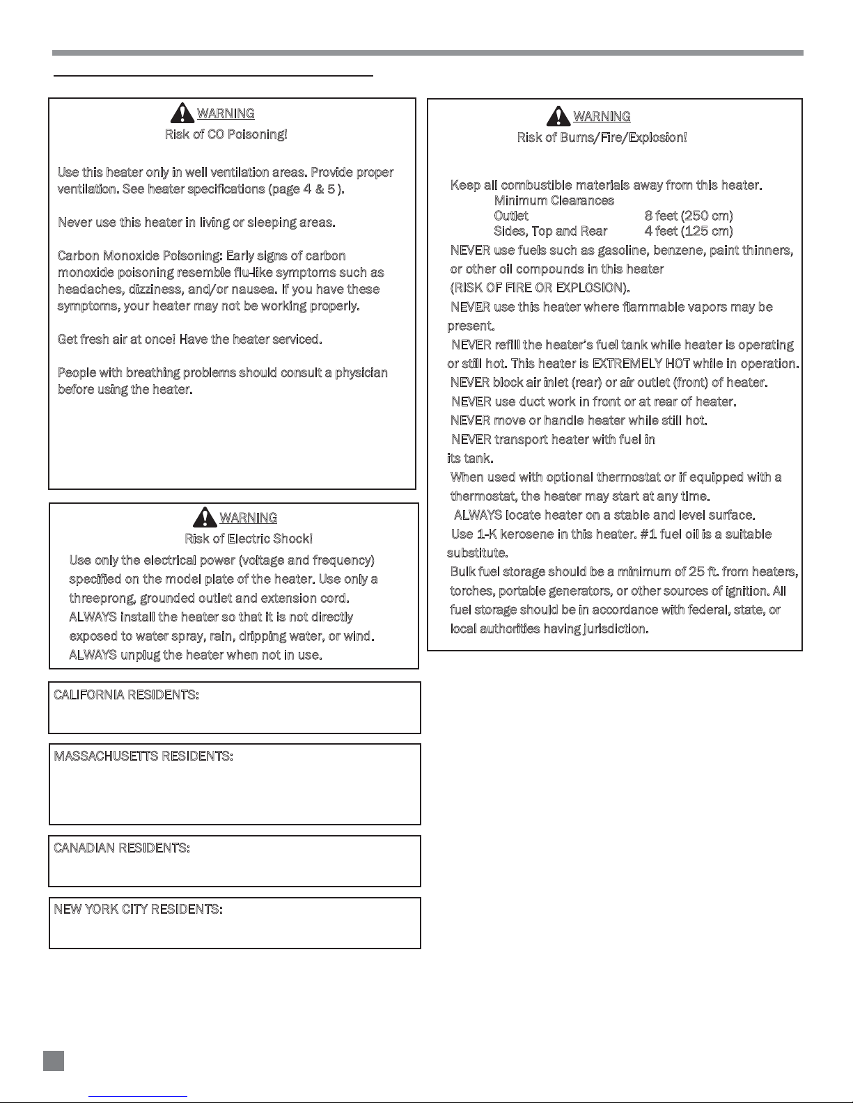
WARNING
Risk of CO Poisoning!
Use this heater only in well ventilation areas. Provide proper
-
ventilation. See heater specifications (page 4 ).
Never use this heater in living or sleeping areas.
-
Carbon Monoxide Poisoning: Early signs of carbon
-
& 5
monoxide poisoning resemble flu-like symptoms such as
headaches, dizziness, and/or nausea. If you have these
symptoms, your heater may not be working properly.
Get fresh air at once! Have the heater serviced.
-
People with breathing problems should consult a physician
-
before using the heater.
WARNING
Risk of Electric Shock!
Use only the electrical power (voltage and frequency)
-
specified on the model plate of the heater. Use only a
three prong, grounded outlet and extension cord.
ALWAYS install the heater so that it is not directly
-
exposed to water spray, rain, dripping water, or wind.
ALWAYS unplug the heater when not in use.
-
WARNING
Risk of Burns/Fire/Explosion!
Keep all combustible materials away from this heater.
-
Minimum Clearances
Outlet 8 feet (250 cm)
Sides, Top and Rear 4 feet (125 cm)
NEVER use fuels such as gasoline, benzene, paint thinners,
-
or other oil compounds in this heater
(RISK OF FIRE OR EXPLOSION).
NEVER use this heater where flam mable vapors may be
-
present.
NEVER refill the heater’s fuel tank while heater is operating
-
or still hot. This heater is EXTREMELY HOT while in operation.
NEVER block air inlet (rear) or air outlet (front) of heater.
-
NEVER use duct work in front or at rear of heater.
-
NEVER move or handle heater while still hot.
-
NEVER transport heater with fuel in
-
its tank.
When used with optional thermostat or if equipped with a
-
thermostat, the heater may start at any time.
ALWAYS locate heater on a stable and level surface.
-
Use 1-K kerosene in this heater. #1 fuel oil is a suitable
-
substitute.
Bulk fuel storage should be a minimum of 25 ft. from heaters,
-
torches, portable generators, or other sources of ignition. All
fuel storage should be in accordance with federal, state, or
local authorities having jurisdiction.
CALIFORNIA RESIDENTS:
This heater produces carbon
monoxide, which is listed by the State of California as a
reproductive toxin under Proposition 65.
M
ASSACHUSETTS RESIDENTS:
Massachusetts state law
prohibits the use of this heater in any building which is used
in whole or in part for human habitation. Use of this heating
device in Massachusetts requires local fire dept. permit
(M.E.L.C. 148, Section 10A).
C
ANADIAN RESIDENTS:
Use of this heater shall be in
accor dance with authorities having juris diction and CSA
Standard B139.
N
EW YORK CITY RESIDENTS:
For use only at construction
sites in accordance with applicable NYC codes under NYCFD
certificate of approval #5034 and 5037
7
Installation and Assembly Instructions
HEATER SPECIFICATIONS
Introduction
Please read this USER’S MANUAL carefully. It will show you
how to assemble, maintain and operate this heater safely
and efficiently to obtain the full benefits of its many
features.
Consumer: Retain these instructions for future reference.
U
npacking
1. Remove all packing items applied to heater for
shipment.
2. Remove all items from carton.
3. Check all items for shipping damage.
If heater is damaged, promptly inform dealer where you
purchased heater.
D
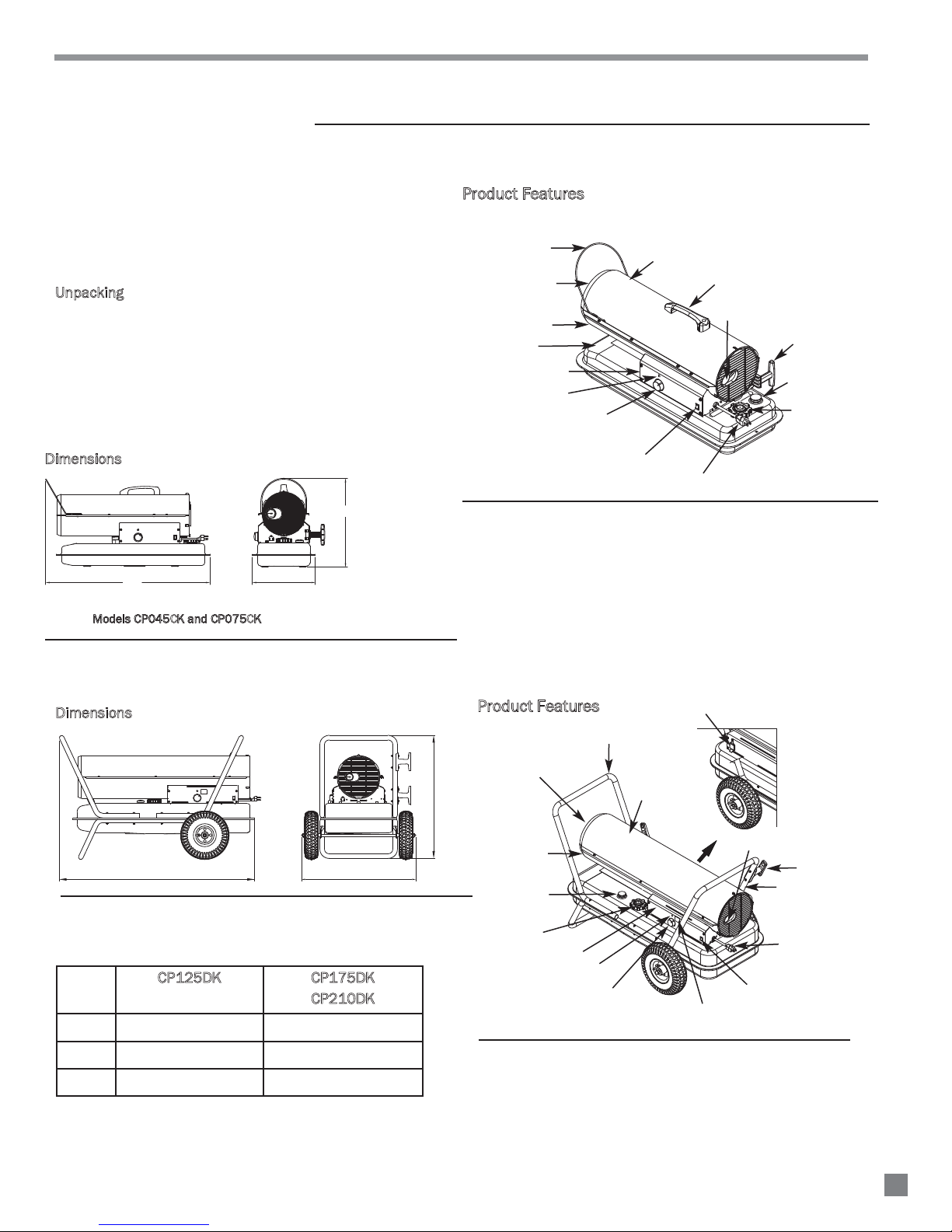
imensions
8
6
10
4
PRESSURE GAUGE
12
2
14
PSI
0
16 3/4"
Product Features
Fan Guard
Hot Air Outlet
Lower Shell
Fuel Tank
Side Cover
Thermostat Knob
(CP075CK model only)
LED Power/Reset Switch
Figure 2.1 - Features
Lamp
Upper Shell
Handle
Pressure Gauge
Cord Wrap
Fuel Gauge
Fuel Cap
Power Cord
32"
MMooddeellss CCPP004455CKK aanndd CCPP007755CKK
Figure 1.1 - Heater Dimensions
D
imensions
L
Figure 1.2 - Heater Dimensions
P125DK CP175DK
C
Height 24.6”
Length 36.1”
11 3/4"
8
6
10
4
PRESSURE GAUGE
12
2
14
PSI
0
W
CP210DK
26.1”
41.8”
Product Features
Electric Outlet
Handle Front
Hot Air Outlet
H
Lower Shell
Upper Shell
Pressure Gauge
Cord Wrap
Fuel Gauge
Fuel Cap
Side Cover
Handle Rear
Power Cord
Lamp
Thermostat
Knob
Room Temp. Display
Power/Reset Switch
Figure 2.2 - Features
Width 23”
24.6”
8
Installation and Assembly Instructions
TOOLS REQUIRED
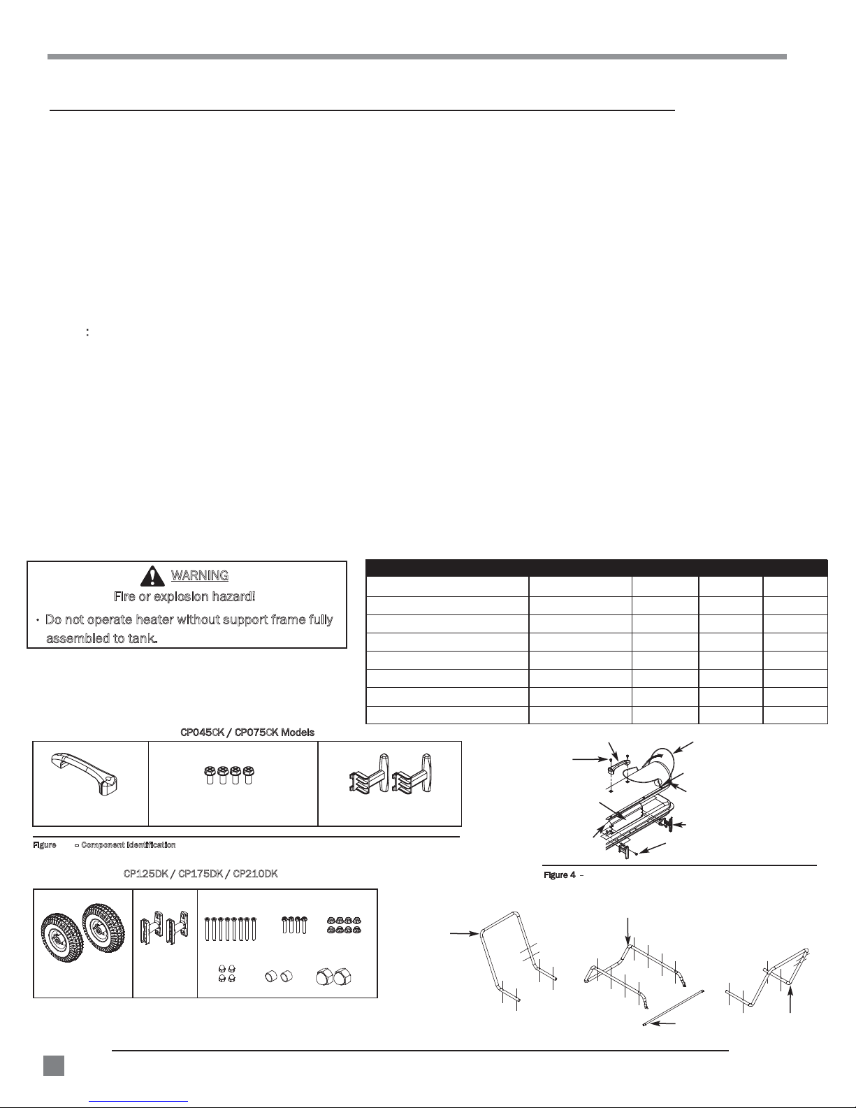
ASSEMBLY
CP045CK/CP075CK
- Medium Phillips screwdriver.
1. Lift front guard for arrow direction and make sure that guard’s wedged portion fits into the slit hole on the upper housing.
2. Align the holes in upper housing with two mounting holes on the handle as shown in Figure 4.
3. Secure handle with screws provided.
4. Insert cord wrap into the rectangle holes on the supporter and align the hole on the cord wrap with the mounting hole on the side
covers shown in Figure 4.
5. Secure cord wrap with screws provided.
CP125DK/CP175DK/CP210DK
- Medium Phillips screwdriver.
- M5 open, or adjustable wrench.
1. Slide threaded axle through the rear section of the wheel support frame.
NOTE
2. Slide one axle bushing on to each side of the axle. Slide one wheel on to each side of the axle.
3. Attach one cap nut on to each side of the threaded axle and tighten well.
4. Place heater on wheel support frame. Make sure the air inlet end (rear) of heater is over wheels. Align the holes on fuel
5. After all screws are inserted, tighten nuts firmly.
6. Align the hole on the handle (front and rear) with the mounting hole on the cord wrap.
7. Insert screws through cord wrap, handles as shown in Figure 5 and attach nut finger tight after each screw is inserted.
8. After all screws are inserted, tighten nuts firmly.
USE CAUTION WHEN INFLATING TIRES:
- Do NOT over inflate tire. Maximum air pressure is 36 PSI.
- Over inflation may lead to serious injury
- NEVER fill tires using an air compressor. A manual pump is recommended
Do not operate heater without support frame fully
assembled to tank.
Figure – Component Identification
When installing wheels, tube valve should face out from support frame (Figure 5).
tank flange. Insert screws through handles (front and rear), fuel tank flange, and wheel support frame as shown in
Figure 5 and attach nut finger tight after each screw is inserted.
Model CP045CK/CP075CK CP125DK CP175DK CP210DK
Wheel Support Frame
Wheels
Front-Handle
Rear-Handle
Axle
Cord Wrap
H
ardware Kit
Handle
Cord Wraps
No
No
No
No
Yes
Yes
Yes No No No
Handle
Screw
Side Cover
Supporter
3.1
Fire or explosion hazard!
Handle
WARNING
CCPP004455CKK // CCPP007755CKK MMooddeellss
Hardware Kit
YesNo
Yes Yes Yes
Yes Yes
Yes Yes
Yes Yes Yes
Yes Yes Yes
Yes Yes
Front Guard
Wedged
Portion
Slit Hole
Cord Wrap
Screw
Yes Yes
Yes
Yes
Yes
CP125DK / /
Wheels
9
Figure 3.2 Component Identification
CP175DK CP210DK
Cord Wraps
Screws
Cap Nut S
Flange Screws
Bushings
Nuts
Cap Nuts L
Front Handle
FFiigguurree 44 – Han dle and Cord Wrap Installation CP045 CK an d CP075CK
Wheel Support Frame
Axle
Rear Handle
 Loading...