

L.B. White Therma Grow Greenhouse HW220 Owner's Manual And Instructions
Available in either
L.P. Gas Vapor
Withdrawal or
Natural Gas
Configurations.
MODELS OUTPUT (kW) FUEL
HW220 64.4
Congratulations!
You have purchased the finest direct fired greenhouse heater available.
Your new L.B. White heater incorporates the benefits from the most experienced
manufacturer of heating products using state-of-the-art technology.
We, at L.B. White, thank you for your confidence in our products and
welcome any suggestions or comments you may have...call us, toll-free,
at (800) 345-7200.
Owner's Manual and Instructions
Therma Grow
™
Greenhouse Heaters
View this manual online at www.lbwhite.com
ATTENTION ALL USERS
This heater has been tested and evaluated by C.S.A. International, in accordance
with Canadian Gas Association Standard for Gas Fired Brooders, CAN 1-2.20-M85.
The heater has been designed, developed, and evaluated for use as a direct gasfired circulating heater for the heating of greenhouses. If you are considering using
this product for any application other than its intended use, then please contact
your fuel gas supplier, or the L.B. White Co., Inc.
150-27888 REV.B
SCAN THIS QR CODE
with your smartphone or
visit http://goo.gl/ny7ua to
view maintenance videos
for L.B.White heaters.*
*Requires an app like QR Droid for Android or
QR Reader for iPhone.

FOR YOUR SAFETY
If you smell gas:
1. Open windows.
2. Don't touch electrical switches.
3. Extinguish any open flame.
4. Immediately call your gas supplier.
WARNING
Fire and Explosion Hazard
■ Not for home or recreational vehicle use.
■ Installation of this heater in a home or
recreational vehicle may result in a fire or
explosion.
■ Fire or explosions can cause property
damage or loss of life.
CONSIGNES DE SECURITE
Si vous sentez une odeur de gaz:
1. Ouvrez le fenetres.
2. Ne touchez pas aux interrupteurs
electriques.
3. Eteignez toute flamme nue.
4. Contactez immediatement votre
compangie de gaz.
CONSIGNES DE SECURITE
Ill es interdit d'utiliser des liquides
inflammables ou degageant des vapeurs
inflammables, a proximite de tout appareil
fonctionnant au gaz.
FOR YOUR SAFETY
Do not store or use gasoline or other
flammable vapors and liquids in the vicinity of
this or any other appliance.
WARNING
Fire and Explosion Hazard
■ Keep solid combustibles a safe distance
away from the heater.
■ Solid combustibles include wood or paper
products, feathers, straw, and dust.
■ Do not use the heater in spaces which
contain or may contain volatile or airborne
combustibles.
■ Volatile or airborne combustibles include
gasoline, solvents, paint thinner, dust
particles or unknown chemicals.
■ Failure to follow these instructions may
result in a fire or explosion.
■ Fire or explosions can lead to property
damage, personal injury or loss of life.
GENERAL HAZARD WARNING
■ Failure to comply with the precautions and instructions provided with this heater, can result in:
— Death
— Serious bodily injury or burns
— Property damage or loss from fire or explosion
— Asphyxiation due to lack of adequate air supply or carbon monoxide poisoning
— Electrical shock
■ Read this Owner’s Manual before installing or using this product.
■ Only properly-trained service people should repair or install this heater.
■ Save this Owner’s Manual for future use and reference.
■ Owner’s Manuals and replacement labels are available at no charge. For assistance, contact
L.B. White at 800-345-7200.
WARNING
■ Proper gas supply pressure must be provided to the inlet of the heater.
■ Refer to rating plate for proper gas supply pressure.
■ Gas pressure in excess of the maximum inlet pressure specified at the heater inlet can cause
fires or explosions.
■ Fires or explosions can lead to serious injury, death, building damage or loss of livestock.
■ Gas pressure below the minimum inlet pressure specified at the heater inlet may cause
improper combustion.
■ Improper combustion can lead to asphyxiation or carbon monoxide poisoning and therefore
serious injury or death to humans and livestock.
2
This Owner's Manual includes all options and accessories
commonly used on this heater. However, depending on the
configuration purchased, some options and accessories
may not be included.
When calling for technical service assistance, or for other
specific information, always have model number,
configuration number and serial number available. This
information is contained on the dataplate.
This manual will instruct you in the operation and care of
your unit. Have your qualified installer review this manual
with you so that you fully understand the heater and how it
functions.
The gas supply line installation, installation of the heater,
and repair and servicing of the heater requires continuing
expert training and knowledge of gas heaters and should
not be attempted by anyone who is not so qualified. See
page 6 for definition of the necessary qualifications.
Contact your local L.B. White distributor or the L.B. White
Co., Inc. for assistance, or if you have any questions about
the use of the equipment or its application.
The L.B. White Co., Inc. has a policy of continuous product
improvement. It reserves the right to change specifications
and design without notice.
SECTION
PAGE
General Information . . . . . . . . . . . . . . . . . . . . . . . . . . . . . . . . . . . . . . . . . . . . . . . . . . . . . . . . . . . . . . . . . . .3
Heater Specifications . . . . . . . . . . . . . . . . . . . . . . . . . . . . . . . . . . . . . . . . . . . . . . . . . . . . . . . . . . . . . . . . . .4
Safety Precautions . . . . . . . . . . . . . . . . . . . . . . . . . . . . . . . . . . . . . . . . . . . . . . . . . . . . . . . . . . . . . . . . . . . .5
Installation Instructions
General . . . . . . . . . . . . . . . . . . . . . . . . . . . . . . . . . . . . . . . . . . . . . . . . . . . . . . . . . . . . . . . . . . . . . . . . .7
Air Discharge Diverter Duct . . . . . . . . . . . . . . . . . . . . . . . . . . . . . . . . . . . . . . . . . . . . . . . . . . . . . . . . .8
Indoor Ventilation Requirements
Air Inlet . . . . . . . . . . . . . . . . . . . . . . . . . . . . . . . . . . . . . . . . . . . . . . . . . . . . . . . . . . . . . . . . . . . . . .9
Exhaust Fan . . . . . . . . . . . . . . . . . . . . . . . . . . . . . . . . . . . . . . . . . . . . . . . . . . . . . . . . . . . . . . . . .10
Hanging the Heater . . . . . . . . . . . . . . . . . . . . . . . . . . . . . . . . . . . . . . . . . . . . . . . . . . . . . . . . . . . . . . .10
Sediment Trap Assembly Instructions . . . . . . . . . . . . . . . . . . . . . . . . . . . . . . . . . . . . . . . . . . . . . . . .11
Heater Control Instructions . . . . . . . . . . . . . . . . . . . . . . . . . . . . . . . . . . . . . . . . . . . . . . . . . . . . . . . .11
Manual Shut-Off Valve, Hose and Regulator Assembly Instructions . . . . . . . . . . . . . . . . . . . . . . . .13
Start-Up Instructions . . . . . . . . . . . . . . . . . . . . . . . . . . . . . . . . . . . . . . . . . . . . . . . . . . . . . . . . . . . . . . . . .14
Shut-Down Instructions . . . . . . . . . . . . . . . . . . . . . . . . . . . . . . . . . . . . . . . . . . . . . . . . . . . . . . . . . . . . . . .14
Cleaning Instructions . . . . . . . . . . . . . . . . . . . . . . . . . . . . . . . . . . . . . . . . . . . . . . . . . . . . . . . . . . . . . . . . .15
Maintenance Instructions . . . . . . . . . . . . . . . . . . . . . . . . . . . . . . . . . . . . . . . . . . . . . . . . . . . . . . . . . . . . .15
Service Instructions
General . . . . . . . . . . . . . . . . . . . . . . . . . . . . . . . . . . . . . . . . . . . . . . . . . . . . . . . . . . . . . . . . . . . . . . . .16
Motor & Fan Wheel Assembly . . . . . . . . . . . . . . . . . . . . . . . . . . . . . . . . . . . . . . . . . . . . . . . . . . . . . .16
Air Proving Switch . . . . . . . . . . . . . . . . . . . . . . . . . . . . . . . . . . . . . . . . . . . . . . . . . . . . . . . . . . . . . . . .17
Testing the Manual reset High Limit Switch . . . . . . . . . . . . . . . . . . . . . . . . . . . . . . . . . . . . . . . . . . .17
Gas Control Valve . . . . . . . . . . . . . . . . . . . . . . . . . . . . . . . . . . . . . . . . . . . . . . . . . . . . . . . . . . . . . . . .17
Gas Pressure Checks . . . . . . . . . . . . . . . . . . . . . . . . . . . . . . . . . . . . . . . . . . . . . . . . . . . . . . . . . . . . .18
Igniter and Flame Sensor . . . . . . . . . . . . . . . . . . . . . . . . . . . . . . . . . . . . . . . . . . . . . . . . . . . . . . . . . .19
Troubleshooting Instructions . . . . . . . . . . . . . . . . . . . . . . . . . . . . . . . . . . . . . . . . . . . . . . . . . . . . . . . . . . .20
Electrical Connection and Ladder Diagram
115 Volt Motor . . . . . . . . . . . . . . . . . . . . . . . . . . . . . . . . . . . . . . . . . . . . . . . . . . . . . . . . . . . . . . . . . .26
230 Volt Motor . . . . . . . . . . . . . . . . . . . . . . . . . . . . . . . . . . . . . . . . . . . . . . . . . . . . . . . . . . . . . . . . . .27
Heater Component Function . . . . . . . . . . . . . . . . . . . . . . . . . . . . . . . . . . . . . . . . . . . . . . . . . . . . . . . . . . .28
Parts Identification
Parts Schematic . . . . . . . . . . . . . . . . . . . . . . . . . . . . . . . . . . . . . . . . . . . . . . . . . . . . . . . . . . . . . . . . .29
Parts List . . . . . . . . . . . . . . . . . . . . . . . . . . . . . . . . . . . . . . . . . . . . . . . . . . . . . . . . . . . . . . . . . . . . . . .30
Warranty Policy . . . . . . . . . . . . . . . . . . . . . . . . . . . . . . . . . . . . . . . . . . . . . . . . . . . . . . . . . . . . . . . . . . . . . .31
Replacement Parts and Service . . . . . . . . . . . . . . . . . . . . . . . . . . . . . . . . . . . . . . . . . . . . . . . . . . . . . . . .31
Table of Contents
General Information
3
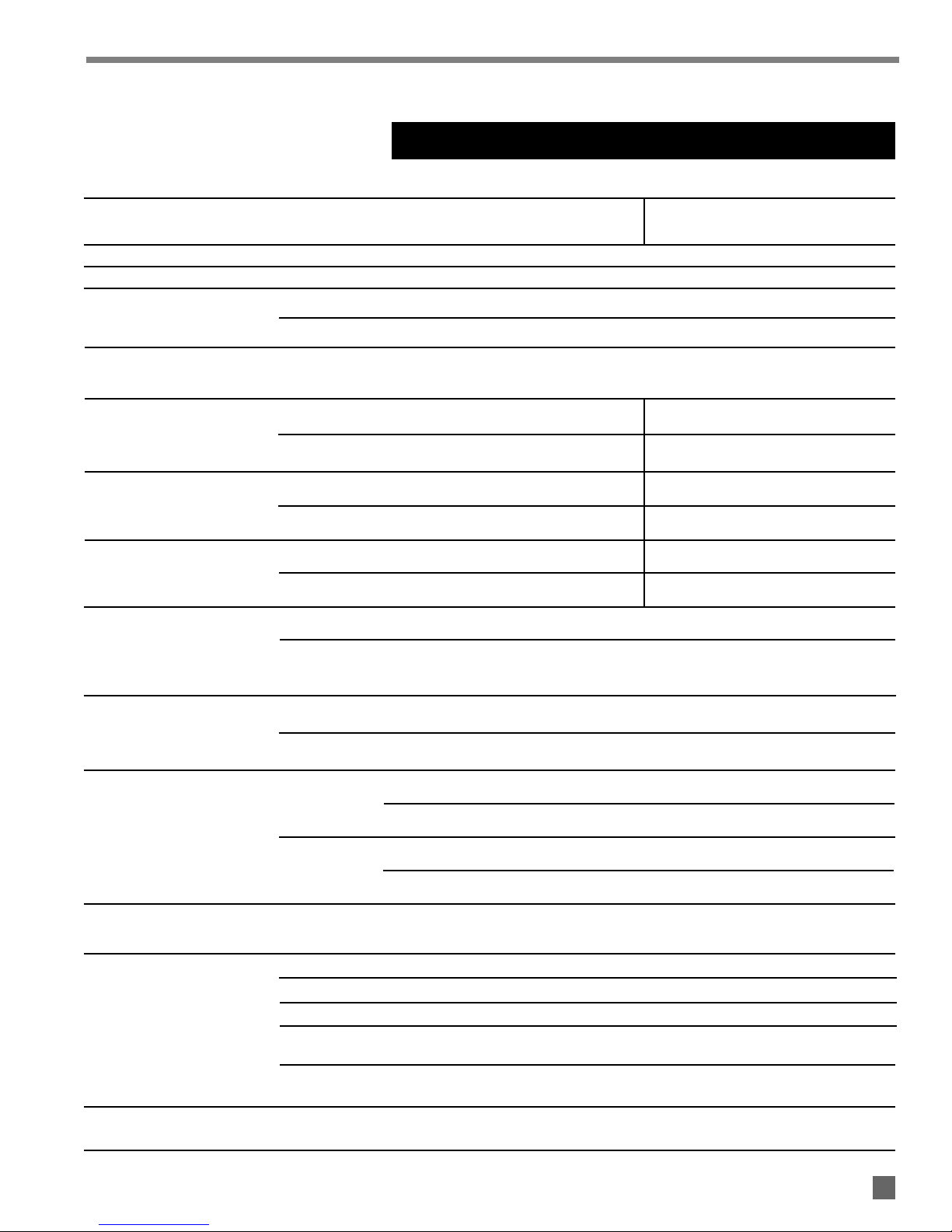
SPECIFICATIONS
HW220
Propane Natural
Fuel Type Gas Gas
Maximum Input (kW) 64.4
Minimum Input (kW) 35.1
EXHAUST FAN 595 m3/hour
SHUTTERED AIR INLET 774 sq. cm.
645 sq. cm.
MAX. 3.36 2.74
MIN. 2.74 1.74
MAX. 1.25 0.77
MIN. 0.35 0.2
MAX. 4.61 kg. 6.23 m3
MIN. 2.52 kg. 3.40 m3
Ball Bearing
372.8 Watts
1,100 RPM
115/60/1
230/60/1
17.1
6.7
8.4
2.6
88.9 x 63.5 x 76.2
TOP 0.3
SIDES 0.3
BACK 0.3
BLOWER
OUTLET
GAS Propane Gas Supply — 1.83
SUPPLY Natural Gas Supply — N/A
(1) Air inlets and exhaust outlets must be electromechanically operated and electrically interlocked with the
heater to prevent heater operation if air inlet and exhaust outlet do not open when heating is required.
Model
Indoor Mounting Air
Exchange Requirements
(1)
Burner Manifold
Pressure (kPa.)
Electrical Supply
(Volts/Hz/Phase)
Amp Draw
Dimensions (cm.)
L x W x H
Minimum Safe
Distances From
Nearest
Combustible
Materials (meters)
STARTING
CONTINUOUS
OPERATION
Motor Characteristics
Fuel Consumption Per
Hour
Inlet Gas Supply Pressure
Acceptable at the Inlet of
the Heater for Purpose of
Input Adjustment (kPa.)
1.83
4
Heater Specifications
Outdoor Mounting Air
Exchange Requirements
SHUTTERED
EXHAUST OUTLET
115 VOLT MOTOR
230 VOLT MOTOR
115 VOLT MOTOR
230 VOLT MOTOR
■ Propane (LP) gas and natural gas have a distinctive
odor. Learn to recognize these odors. (Reference Fuel
Gas Odor and Odor Fading sections above.
■
If you have not been properly trained in repair and service
of propane (LP) gas and natural gas fueled heaters, then
do not attempt to light heater, perform service or repairs,
or make any adjustments to the heater on propane (LP)
gas or natural gas fuel system.
■ Even if you are not properly trained in the service and
repair of the heater, ALWAYS be consciously aware of
the odors of propane (LP) gas and natural gas.
■ A periodic sniff test around the heater or at the heater’s
joints; i.e. hose, connections, etc., is a good safety
practice under any conditions. If you smell even a small
amount of gas, CONTACT YOUR FUEL GAS SUPPLIER
IMMEDIATELY. DO NOT WAIT!
LP gas and natural gas have man-made odorants added specifically for detection of fuel gas leaks.
If a gas leak occurs, you should be able to smell the fuel gas
THAT’S YOUR SIGNAL TO GO INTO IMMEDIATE ACTION!
■ Do not take any action that could ignite the fuel gas. Do
not operate any electrical switches. Do not pull any
power supply or extension cords. Do not light matches
or any other source of flame. Do not use your
telephone.
■ Get everyone out of the building and away from the area
immediately.
■ Close all propane (LP) gas tank or cylinder fuel supply
valves, or the main fuel supply valve located at the
meter if you use natural gas.
■ Propane (LP) gas is heavier than air and may settle in
low areas. When you have reason to suspect a propane
leak, keep out of all low areas.
■ Natural gas is lighter than air and can collect around
rafters or ceilings.
■ Use your neighbor’s phone and call your fuel gas
supplier and your fire department. Do not re-enter the
building or area.
■ Stay out of the building and away from the area until
declared safe by the firefighters and your fuel gas
supplier.
■ FINALLY, let the fuel gas service person and the
firefighters check for escaped gas. Have them air out
the building and area before you return. Properly
trained service people must repair the leak, check for
further leakages, and then relight the appliance for you.
WARNING
■ Do not use this heater for heating human living
quarters.
■ Do not use in areas without proper air exchange. See
air exchange requirements on page 4 or on heater’s
dataplate.
■ Exhaust fans, supply air inlets, or exhaust fan outlets
must not be obstructed.
■ Proper air exchange must be provided for either indoor
or outdoor mount installations.
■ Refer to the specification section and installation
instructions of the heater’s Owner’s Manual, heater
dataplate, or contact the L.B. White Company to
determine air exchange requirements of the heater.
■ Lack of proper air exchange will lead to improper
combustion.
■ Improper combustion can lead to carbon monoxide
poisoning in humans leading to serious injury or death.
Symptoms of carbon monoxide poisoning can include
headaches, dizziness and difficulty in breathing.
Asphyxiation Hazard
■ Some people cannot smell well. Some people cannot
smell the odor of the man-made chemical added to
propane (LP) or natural gas. You must determine if
you can smell the odorant in these fuel gases.
■ Learn to recognize the odor of propane (LP) gas and
natural gas. Local propane (LP) gas dealers and your
local natural gas supplier (utility) will be more than
happy to give you a scratch and sniff pamphlet. Use it
to become familiar with the fuel gas odor.
■ Smoking can decrease your ability to smell. Being
around an odor for a period of time can affect your
sensitivity to that particular odor.
■ The odorant in propane (LP) gas and natural gas is
colorless and the intensity of its odor can fade under
some circumstances.
■ If there is an underground leak, the movement of gas
through the soil can filter the odorant.
■ Propane (LP) gas odor may differ in intensity at different
levels. Since propane (LP) gas is heavier than air, there
may be more odor at lower levels.
■ Always be sensitive to the slightest gas odor. If you
continue to detect any gas odor, no matter how small,
treat it as a serious leak. Immediately go into action as
discussed previously.
5
Safety Precautions
FUEL GAS ODOR
ODOR FADING -- NO ODOR DETECTED
ATTENTION -- CRITICAL POINTS TO REMEMBER!

1. Do not attempt to install, repair, or service this heater
or the gas supply line unless you have continuing
expert training and knowledge of gas heaters.
Qualifications for service and installation of this
equipment are as follows:
a.
To be a qualified gas heater service person, you
must have sufficient training and experience to
handle all aspects of gas-fired heater installation,
service and repair. This includes the task of
installation, troubleshooting, replacement of
defective parts and testing of the heater. You
must be able to place the heater into a continuing
safe and normal operating condition. You must
completely familiarize yourself with each model
heater by reading and complying with the safety
instructions, labels, Owner’s Manual, etc., that is
provided with each heater.
b.
To be a qualified gas installation person, you must
have sufficient training and experience to handle
all aspects of installing, repairing and altering gas
lines, including selecting and installing the proper
equipment, and selecting proper pipe and tank
size to be used. This must be done in accordance
with all local, state and national codes as well as
the manufacturer’s requirements.
2. All installations and applications of L.B. White heaters
must meet all relevant local, state and national
codes. Included are L.P. gas, natural gas, electrical,
and safety codes. Your local fuel gas supplier, a local
licensed electrician, the local fire department or
similar government agencies, or your insurance agent
can help you determine code requirements. Refer to
the following:
-- CAN 1 -B149.1 or CAN1-B149.2 Installation
Codes
-- CSA C22.1, Part1 Standard Canadian
Electrical Code, CSA C22.2 No.3, Electrical
Features of Fuel Burning Equipment
3. Do not move, handle, or service heater while in
operation or connected to a power or fuel supply.
4. This heater may be installed in areas subject to
washdown. This heater may only be washed on the
external case assembly—see Cleaning Instructions.
Do not wash the interior of the heater. Use only
compressed air, soft brush or dry cloth to clean the
interior of the heater and it’s components. After
external washdown, do not operate this heater until it
is completely dry. In any event, do not operate the
heater for at least one hour after external washdown.
5. For safety, this heater is equipped with a manual
reset high-limit switch and an air proving switch.
Never operate this heater with any safety device that
has been bypassed. Do not operate this heater
unless all of these features are fully functioning.
6. Do not operate the heater with its door open or panel
removed.
7. Do not locate fuel gas containers or fuel supply
hoses anywhere near the blower outlet of the heater.
8. Do not block air intakes or discharge outlets of the
heater. Doing so may cause improper combustion or
damage to heater components leading to property
damage or plant loss.
9. The hose assembly shall be visually inspected on an
annual basis. If it is evident there is excessive
abrasion or wear, or if the hose is cut, it must be
replaced prior to the heater being put into operation.
The hose assembly shall be protected from building
materials and contact with hot surfaces during use.
The hose assembly shall be that specified by the
manufacturer. See parts list.
10. Check for gas leaks and proper function upon heater
installation, at beginning of heating season or when
relocating.
11. This heater should be inspected for proper operation
by a qualified service person before the start of fall
heating season and at least annually.
12. Always turn off the gas supply to the heater if the
heater is not going to be used.
13. Heaters requiring 230 volts electrical supply must
have electrical wiring consisting of two hot leads, a
neutral lead, and a ground lead. All GreenGro
heaters, regardless of voltage, must be properly
connected to a grounded electrical supply. Failure
to use a grounded electrical supply can result in
electrical shock, serious injury, or death.
14. Direct ignition heaters will make up to three trials for
ignition. If ignition is not achieved, the control system
will lock out the gas control valve. If gas is smelled
after system lock out has occurred, immediately close
all fuel supply valves. Do not relight until you are sure
that all gas that may have accumulated has cleared
away. In any event, do not relight for at least 5
minutes.
15. In a hanging type installation, rigid pipe or copper
tubing coupled directly to the heater may cause gas
leaks during movement, and therefore must not be
used. Use only gas hose assemblies that are rated
and approved for L.P.gas and natural gas in a hanging
type of installation.
16. Installations not using the gas hose supplied with
this heater must connect dimensionally using
American National Standard Wrought Steel and
Wrought Iron Pipe B36/10-1970. (Aluminum piping
or tubing shall not be used.) Copper tubing when
used for conveying natural gas, shall be internally
tinned or equivalently treated to resist sulphur.
6
Direct fired heaters discharge combustion by-products with
the heated air in to the area being heated. These include
CO, CO2, NO, NO2, and Ethylene. These gases can result in
harm to the worker or the plants.
This greenhouse heater has been specificallyveloped for
very low levels of these combustion by-products. However,
it is necessary to have an exchange of air within the
greenhouse to avoid accumulation of these gases to a
harmful level over an extended period of operating time.
Greenhouses have a natural air leakage factor. This natural
leakage is influenced by the design and physical condition
of the greenhouse as well as wind conditions and other
factors. This natural leakage factor can not be relied upon
as being sufficient to provide the necessary air exchange
within the greenhouse. Proper installation of this heater
must include provision for adequate air exchange as
follows:
Indoor Mounted Heater:
■ An exhaust fan capable of providing at least 595
m3/hour of discharge air.
■ An inlet shuttered louver of at least 774 sq.cm.
area.
■ The inlet shutters must be electromachanically
operated and electrically interlocked with the
heater such that the heater can not operate if the
inlet shutters do not open when heating is
required.
■ Refer to Indoor Ventilation Requirements in this
manual.
Outdoor Mounted Heater:
■ An exhaust shuttered louver of at least 645 sq. cm.
area.
1. Read all safety precautions and follow L.B. White
recommendations when installing this heater. If
during the installation or relocating of heater, you
suspect that a part is damaged or defective, call a
qualified service agency for repair or replacement.
2.
Make sure the heater is properly positioned before use
and is hung level. Observe and obey all minimum safe
distances of the heater to the nearest combustible
materials. Minimum safe distances are given on the
heater nameplate and on page 4 of this manual.
3. The heater may be used either indoors or outdoors.
For heaters intended for outdoor installation, the
heater is to be installed at least 45.7 cm. above the
ground or to a height that would prevent snow
blockage of heater’s air inlet. Refer to instructions
provided in the optional L.B. White outdoor mounting
and ducting kit, part number 23579.
4.
The heater must have the proper gas regulator installed
for the application. A regulator must be connected to
the gas supply so that gas pressure at the inlet to the
gas valve is regulated within the range specified on the
dataplate at all times. Contact your gas supplier, or the
L.B. White Co., Inc. if you have any questions.
5. The heater’s gas regulator (with pressure relief valve)
should be installed outside of building. Any
regulators inside the buildings must be properly
vented to the outside. Local, state and national
codes always apply to regulator installation. Natural
gas regulators with vent limiting device may be
mounted indoors without venting to outdoors.
6.
All gas pressure regulators must be installed in strict
accordance with the manufacturer’s safety instructions.
These instructions accompany each regulator.
7. Insure that all accessories that ship within the heater
have been removed from inside of heater and
installed. This pertains to air diverters, hose,
regulators, etc.
8. Make certain that a sediment trap is installed at the
gas valve inlet to prevent foreign materials (pipe
compound, pipe chips and scale) from entering the
gas valve. Debris blown into the gas valve may cause
that valve to malfunction resulting in a serious gas
leak that could result in a possible fire or explosion
causing loss of products, building or even life. A
properly installed sediment trap will keep foreign
materials from entering the gas valve and protect the
safe functioning of that important safety component.
9. Any heater connected to a piping system must have
an accessible, approved manual shut off valve
installed within 1.83 m. of the heater it serves.
10. Check all connections for gas leaks using approved
gas leak detectors. Gas leak testing is performed as
follows:
-- Check all pipe connections, hose connections,
fittings and adapters upstream of the gas
control with approved gas leak detectors.
-- In the event a gas leak is detected, check the
components involved for cleanliness and
proper application of pipe compound before
further tightening.
-- Furthermore tighten the gas connections as
necessary to stop the leak.
-- After all connections are checked and any
leaks are stopped, turn on the main burner.
-- Stand clear while the main burner ignites to
prevent injury caused from hidden leaks that
could cause flashback.
-- With the main burner in operation, check all
connections, hose connections, fittings and
joints as well as the gas control valve inlet and
outlet connections with approved gas leak
detectors.
7
Installation Instructions
GENERAL
WARNING
Fire and Explosion Hazard
■ Do not use open flame (matches, torches, candles,
etc.) in checking for gas leaks.
■ Use only approved leak detectors.
■ Failure to follow this warning can lead to fires or
explosions.
■ Fires or explosions can lead to property damage,
personal injury or loss of life.
-- If a leak is detected, check the components
involved for cleanliness in the thread areas
and proper application of pipe compound
before further tightening.
-- Tighten the gas connection as necessary to
stop the leak.
-- If necessary, replace the parts or components
involved if the leak cannot be stopped.
-- Ensure all gas leaks have been identified and
repaired before proceeding.
11. A qualified service agency must check for proper
operating gas pressure upon installation of the
heater.
12. Light according to instructions on heater or within
owner's manual.
13. It is extremely important to use the proper size and
type of gas supply line to assure proper functioning of
the heater. Contact your fuel gas supplier for proper
line sizing and installation.
14. This heater can be configured for use with either L.P.
gas vapor withdrawal or natural gas. Consult the
dataplate for the gas configuration of the specific
heater. Do not use the heater in an L.P. gas liquid
withdrawal system or application. If you are in doubt,
contact the L.B. White Co., Inc.
15. Eventually, like all electrical/mechanical devices, the
thermostat can fail. Thermostat failure may result in
either an underheating or overheating condition
which may damage or kill plants. Plants should be
protected by a separate back-up control system that
limits high and low temperatures and also activates
appropriate alarms.
16. Take time to understand how to operate and maintain
the heater by using this Owner’s Manual. Make sure
you know how to shut off the gas supply to the
building and also to the individual heater. Contact
your fuel gas supplier if you have any questions.
17. Any defects found in performing any of the service or
maintenance procedures must be eliminated and
defective parts replaced immediately. The heater
must be retested by properly qualified service
personnel before placing the heater back into use.
18. Do not exceed input rating stamped on the dataplate
of the heater. Do not exceed the burner manifold
pressure stated on the dataplate. Do not use an
orifice size different than specified for the specific
input rating of this heater, fuel type configuration and
altitude.
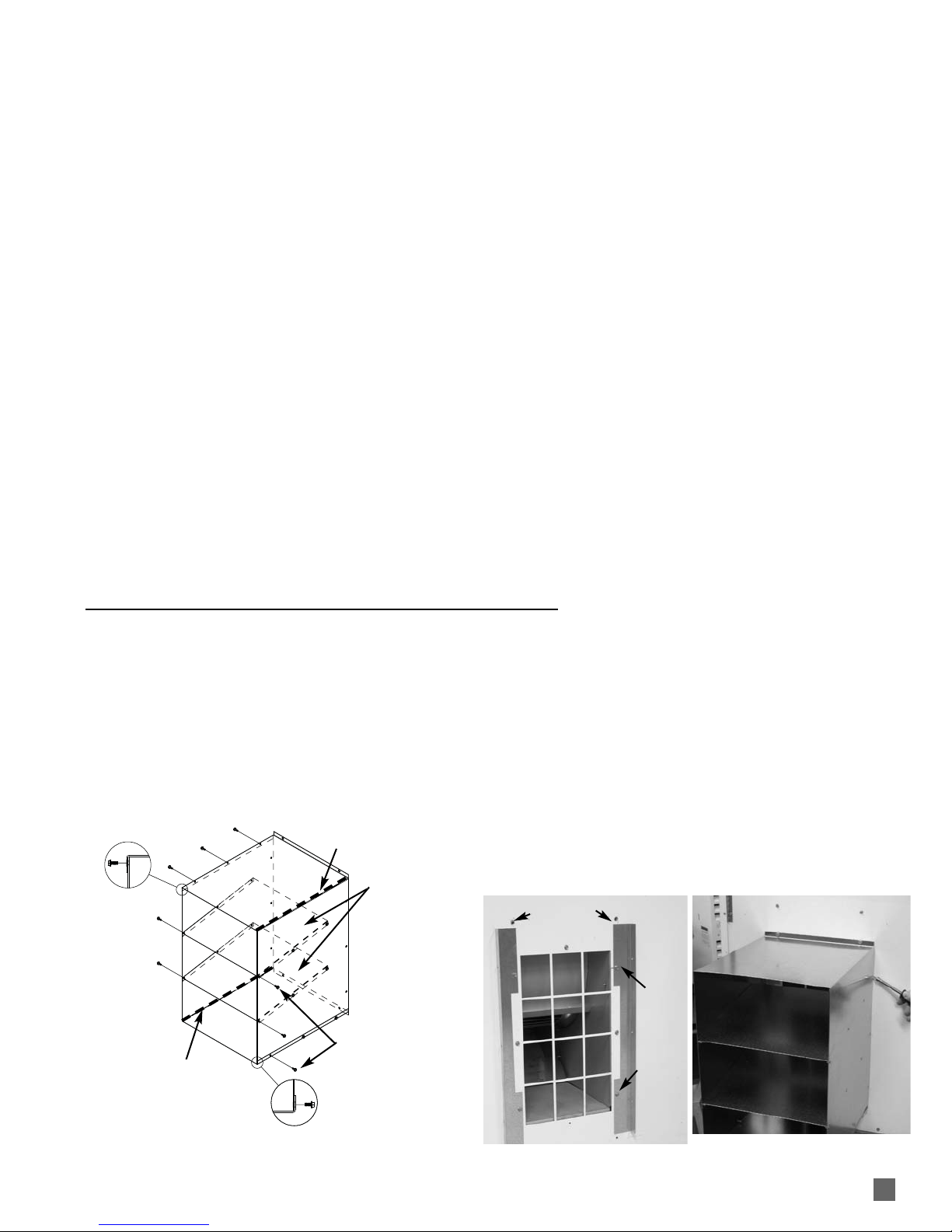
1. The air discharge diverter duct provides improved
directional air flow and greater heat throw, beneficial
in heating long houses. Use the duct only on indoor
mounted heaters. Do not use the diverter when the
heater is mounted outside the greenhouse. The
diverter duct requires hand forming prior to assembly.
Make 90 degree bends utilizing the perforations
provided. Assemble as shown in Fig. 1.
.
FIG. 1
2. Remove the upper and lower screws at both sides of
the blower outlet, and the two screws at outlet top.
3. Install flanges as shown in Fig. 2, using the same
screws. Tighten the screws securely.
4. Position the diverter over the flanges. Align holes in
diverter to flange holes and to vacant holes at top
and bottom of blower outlet.
5. Fasten the diverter to the flanges with the screws
provided. See Fig. 3.
FIG. 2 FIG. 3
AIR DISCHARGE DIVERTER DUCT
Part Number 26025 (Accessory)
UPPER
SCREW
LOWER
SCREW
SCREWS REMOVED AT OUTLET TOP
PERFORATIONS
PERFORATIONS
VANES
MUST BE
DIRECTED
DOWNWARD
SCREWS
FROM KIT
8
9
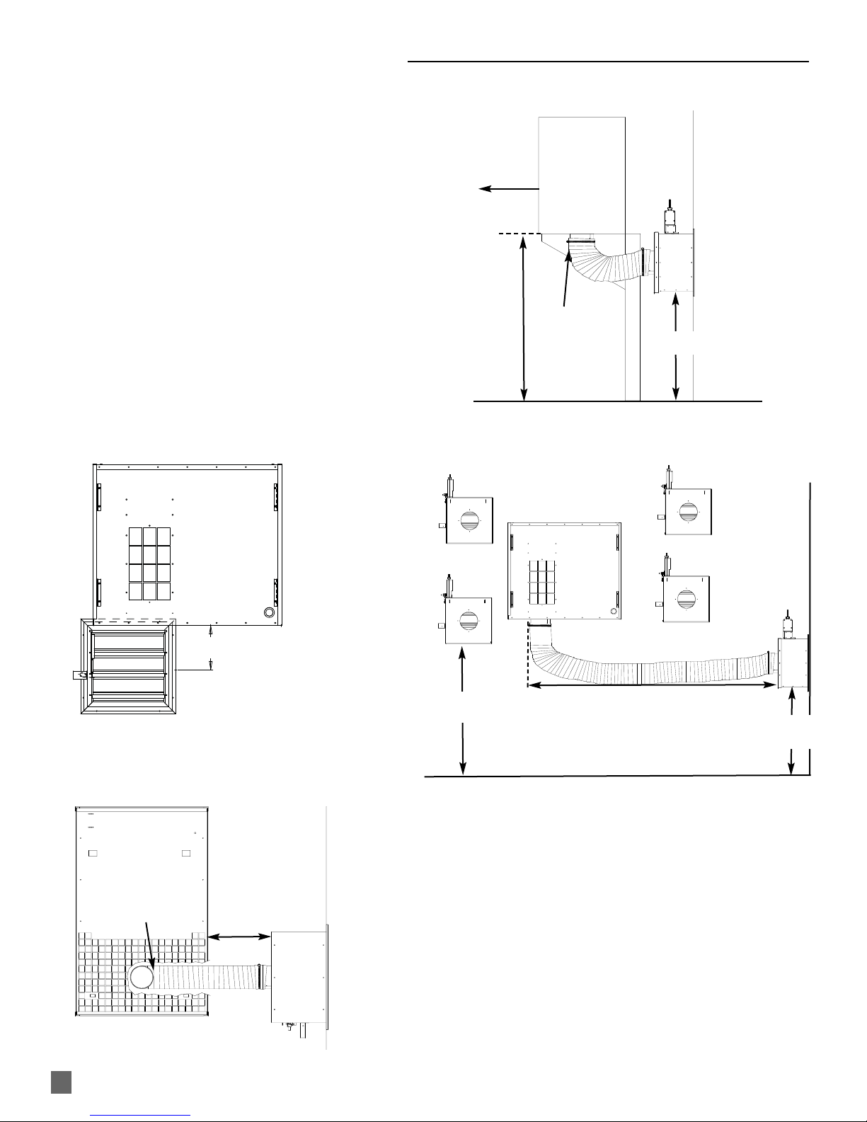
INDOOR VENTILATION REQUIREMENTS
This heater requires a properly sized motorized air inlet shutter,
flexible duct, and exhaust fan. All items must be installed when
the heater is located within the greenhouse.
These components, along with specific instructions, are
provided in the indoor ventilation kit, part number 25985.
Air Inlet
Ideally the air inlet shutter should be located as shown in
Fig.4a, 4b, and 4c. However, it may also be installed in any
other location on an end or side wall, especially if water, gas, or
electrical lines create interference See Fig.4d for alternate
locations at end or side walls.
Regardless of air inlet location, the flexible duct (included with
the ventilation kit) must be installed. The duct must be cut to
proper length to prevent sagging and kinks from preventing
proper air flow to the heater. Separate duct installation
instructions are provided in the duct kit.
Ensure the motorized air inlet and the heater’s air inlet are
kept free of any blockages.
FIG. 4a Blower Outlet View
FIG. 4c Side View
FIG. 4d Alternate Air Inlet Locations
1 1/2 FT MAX.
MOTORIZED AIR INLET
ALIGNED TO AIR INLET
IN BASE OF HEATER
MOTORIZED AIR INLET SHOWN
WITHOUT DUCT ATTACHED FOR CLARITY
OUTSIDE AIR SOURCE
45.7 cm MINIMUM
CUT DUCT TO PROPER LENGTH
NO KINKS OR SAGGING
10 FT. MAXIMUM FROM AIR INLET AT HEATER TO MOTORIZED AIR
INLET SHUTTER, REGARDLESS OF INLET LOCATION. DUCT MUST BE
INSTALLED
END WALL
GROUND
HEATER
AIR DISCHARGE
OUTSIDE AIR
SOURCE
EXTERIOR
INTERIOR
CENTERED
AIR INLET
DUCT WITH COLLAR
CENTERED TO AIR INLET
OF HEATER
FIG. 4b Underside View
61 cm MIN.
END WALL
DUCT ATTACHED
TO AIR INLET OF
HEATER, AND CUT TO
PROPER LENGTH. (NO
KINKS OR SAGGING)
45.7 cm MIN.*
45.7 cm
MIN.*
* THE MOTORIZED AIR INLET MUST BE INSTALLED A MINIMUM OF 45.7 cm ABOVE THE
GROUND OR TO A HEIGHT NECESSARY TO PREVENT BLOCKAGE FROM OBSTRUCTIONS
(EXAMPLES: SNOW, EXTERIOR PLANT GROWTH, ETC.)
SIDE WALL
45.7 cm
MIN.*
45.7 cm MAX.
 Loading...