

L.B. White Oval 80 v.2, Sentinel v.2, Oval 80, Sentinel Owner's Manual And Instructions
Attention
The Oval 80 heater has been
designed, tested, and evaluated
by the L. B. White Company as a
radiant tube heater according to
the requirements of standard IAS
U.S. Requirements 8-94. Specifi c
Sentinel radiant tube heaters have
been tested and evaluated by the
CSA Group in accordance with the
requirements of standard IAS u.S.
Requirements 8-94 and are listed
and approved by the CSA Group
as a direct gas-fi red radiant tube
heaters. All heaters are designed
specifi cally for the intended use
of heating poultry confi nement
buildings.
CHECK WITH YOUR
LOCAL FIRE SAFETY AU-
THORITY, YOUR LOCAL FUEL
GAS SUPPLIER, OR THE L.B.
WHITE COMPANY IF YOU
HAVE QUESTIONS REGARD-
ING APPLICATIONS.
www.lbwhite.com
SCAN THIS
with your smartphone or
visit http://goo.gl/yyKxJo to
view maintenance videos
for L.B.White heaters.
WORLD PROVIDER - INNOVATIVE HEATING SOLUTIONS
411 Mason Street, Onalaska, WI 54650 • 800-345-7200 • 608-783-5691 • 608-783-6115 (fax) • www.lbwhite.com
Congratulations!
You have purchased the fi nest radiant tube heater available for
the heating of poultry confi nement buildings.
Your new L.B. White radiant heater incorporates the benefi ts
from the most experienced manufacturer of heating products
using state-of-the-art technology.
We, at L.B. White, thank you for your confi dence in our products
and welcome any suggestions or comments you may have...call
us toll free at (800) 345-7200.
Propane Vapor Withdrawal
or Natural Gas
(1) Listed under U.S. Patent #: 9,303,880
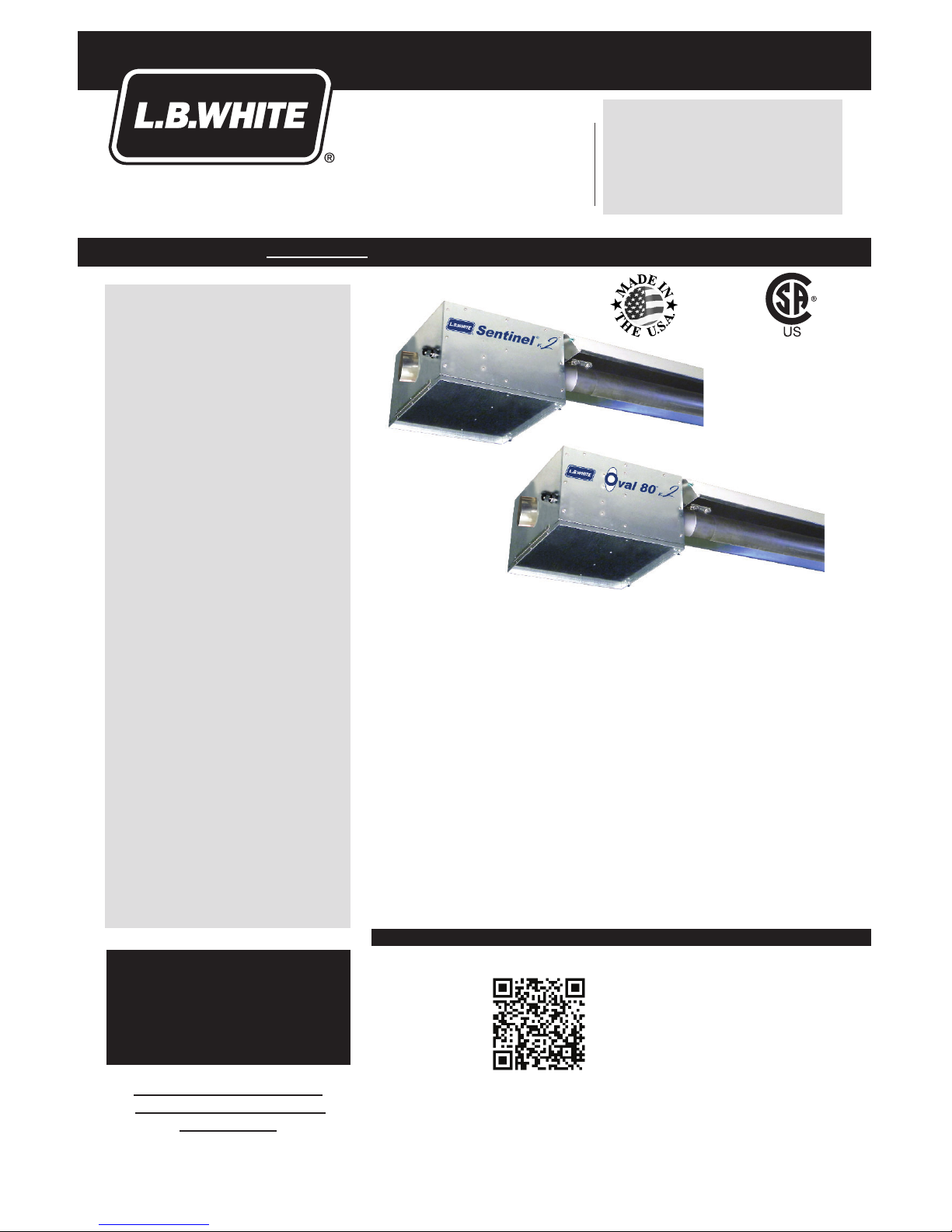
Oval 80 v.2
Sentinel v.2
Radiant Tube Heaters
AR80 (1)
*AT 100
*AT 125
*AT 150
80,000 Btuh
100,000 Btuh
125,000 Btuh
150,000 Btuh
Owner’s Manual and Instructions
View this manual online at www.lbwhite.com
* Requires an app like QR Droid
for Android or for iPhone
SEE ASSEMBLY
INSTRUCTIONS
INSIDE
Please refer to important
elevation information on
inside cover.
*Some models
CSA-US approved.
See specifi cations page.
Oval 80 v.2 and Sentinel v.2 Radiant Tube Heaters
www.lbwhite.com
Owner’s Manual • Oval 80 v.2 and Sentinel v.2
2
TABLE OF CONTENTS
Heater Specifi cations ......................................................................................................4
General Information ........................................................................................................5
Safe Clearance From Combustibles ...............................................................................5
Temperature Sensor Location ........................................................................................5
Safety Precautions .........................................................................................................6
Inlet Air Requirements ....................................................................................................9
General Installation Instructions ...................................................................................10
Initial Set-Up .................................................................................................................12
Hanging the Tubes .......................................................................................................12
Installing Refl ectors & Supports ...................................................................................14
Air Turbulation Strips & Vent .........................................................................................15
Sediment Trap Assembly ..............................................................................................15
Manual Shut Off Valve, Hose & Regulator Assembly ...................................................15
Heater Controls ............................................................................................................16
Connecting Series Tap Thermostat ..............................................................................16
Start-Up Instructions .....................................................................................................16
Shut-Down Instructions ................................................................................................17
Cleaning Instructions ....................................................................................................17
Maintenance Instructions ..............................................................................................18
General Service Instructions ........................................................................................18
Igniter .................................................................................................................19
Motor and Fan ....................................................................................................20
Air Differential Pressure, Tubing & Pressure Orifi ces ........................................20
Air Differential Pressure Switch ..........................................................................21
Gas Control Valve ..............................................................................................22
Transformer ........................................................................................................22
Ignition Control ...................................................................................................23
Gas Pressure Checks ........................................................................................23
Troubleshooting Information .........................................................................................25
Electrical Connection and Ladder Diagram ..................................................................29
Heater Component Function ........................................................................................30
Service Parts Identifi cation
Service Parts Identifi cation Schematic - Tube/Refl ector ....................................32
Tube/Refl ector Parts List ....................................................................................33
Service Parts Identifi cation Schematic - Burner Box ..........................................34
Burner Box Parts List .........................................................................................35
Warranty Policy.............................................................................................................36
Replacement Parts and Service ...................................................................................36
WARNING
Standard products are manufactured to operate at optimum effi ciency at
elevations between 0 and 2000 ft. above sea level.
If operated at higher elevations the product will not function correctly and may
function in an unsafe nature. Products providing proper operation for alternate
elevations may be available.
If you require a high elevation product, did not specify when ordering, and/or
the box this unit came in does not have an alternate altitude designation
sticker please contact technical support.
Oval 80 v.2 and Sentinel v.2 Radiant Tube Heaters
Owner’s Manual • Oval 80 v.2 and Sentinel v.2
3
WARNING
FIRE, BURN, INHALATION, AND
EXPLOSION HAZARD
■ KEEP SOLID COMBUSTIBLES A SAFE DIS-
TANCE AWAY FROM THE HEATER.
■ SOLID COMBUSTIBLES INCLUDE WOOD,
PAPER PRODUCTS, FEATHERS, STRAW AND
DUST.
■ DO NOT USE THE HEATER IN SPACES WHICH
CONTAIN OR MAY CONTAIN VOLATILE OR
AIRBORNE COMBUSTIBLES.
■ VOLATILE OR AIRBORNE COMBUSTIBLES
INCLUDE PIT GASES, GASOLINE, SOLVENTS,
PAINT THINNER, DUST PARTICLES OR UNKNOWN CHEMICALS.
■ FAILURE TO FOLLOW THESE INSTRUCTIONS
MAY RESULT IN A FIRE OR EXPLOSION.
■ FIRE OR EXPLOSIONS CAN LEAD TO
PROPERTY DAMAGE, PERSONAL INJURY OR
DEATH.
FOR YOUR SAFETY
If you smell gas:
1. Open windows.
2. Don’t touch electrical switches.
3. Extinguish any open fl ame.
4. Immediately call your gas supplier.
FOR YOUR SAFETY
Do not store or use gasoline or other fl am-
mable vapors and liquids in the vicinity of this
or any other appliance.
GENERAL HAZARD WARNING
■ FAILURE TO COMPLY WITH THE PRECAUTIONS AND INSTRUCTIONS PROVIDED WITH
THIS HEATER CAN RESULT IN:
— DEATH
— SERIOUS BODILY INJURY OR BURNS
— PROPERTY DAMAGE OR LOSS FROM FIRE OR EXPLOSION
— ASPHYXIATION DUE TO LACK OF ADEQUATE AIR SUPPLY OR CARBON MONOXIDE
POISONING
— ELECTRICAL SHOCK
■ READ THIS OWNER’S MANUAL BEFORE INSTALLING OR USING THIS PRODUCT.
■ ONLY PERSONS WHO CAN READ, UNDERSTAND, AND FOLLOW THE INSTRUCTIONS
SHOULD USE OR SERVICE THIS HEATER.
■ SAVE THIS OWNER’S MANUAL FOR FUTURE USE AND REFERENCE.
■ OWNER’S MANUALS AND REPLACEMENT LABELS ARE AVAILABLE AT NO CHARGE. SEE
WEBSITE, OR FOR ASSISTANCE, CONTACT L.B. WHITE AT 1-800-345-7200.
WARNING
■ PROPER GAS SUPPLY PRESSURE MUST BE PROVIDED TO THE INLET OF THE HEATER.
■ REFER TO DATA PLATE FOR PROPER GAS SUPPLY PRESSURE.
■ GAS PRESSURE IN EXCESS OF THE MAXIMUM INLET PRESSURE SPECIFIED AT THE
HEATER INLET CAN CAUSE FIRES OR EXPLOSIONS.
■ FIRES OR EXPLOSIONS CAN LEAD TO SERIOUS INJURY, DEATH, OR BUILDING
DAMAGE.
■ GAS PRESSURE BELOW THE MINIMUM INLET PRESSURE SPECIFIED AT THE HEATER INLET
MAY CAUSE IMPROPER COMBUSTION.
■ IMPROPER COMBUSTION CAN LEAD TO ASPHYXIATION OR CARBON MONOXIDE POISON-
ING AND THEREFORE SERIOUS INJURY OR DEATH.
WARNING
FIRE AND EXPLOSION HAZARD
■ NOT FOR HOME OR RECREATIONAL VEHICLE USE.
■ INSTALLATION OF THIS HEATER IN A HOME OR RECREATIONAL VEHICLE MAY RESULT IN A
FIRE OR EXPLOSION.
■ FIRE OR EXPLOSIONS CAN CAUSE PROPERTY DAMAGE OR LOSS OF LIFE.
WARNING
Cancer and reproductive harm.
See www.P65Warnings.ca.gov.
Oval 80 v.2 and Sentinel v.2 Radiant Tube Heaters
www.lbwhite.com
Owner’s Manual • Oval 80 v.2 and Sentinel v.2
4
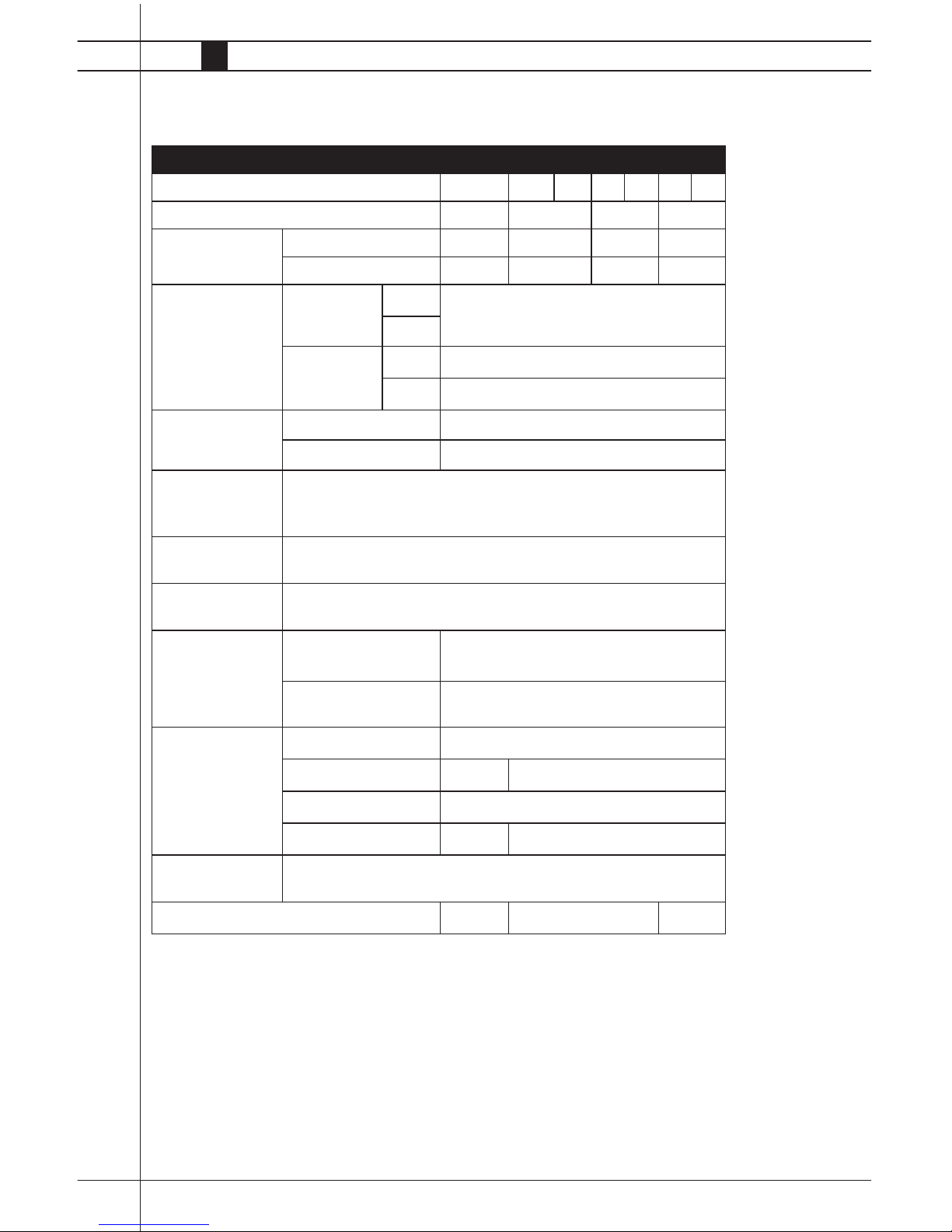
Specifications
AR080 AT100 AT125 AT150
Available Tube Lengths (ft.) 20 30 40 40 50 40 50
Maximum Input per Hour BTU/H 80,000 100,000 125,000 150,000
Fuel Consumption
per Hour (Max.)
LPG (lbs.) 3.7 4.6 5.8 7.1
NG (ft.3) 80 100 125 150
Gas supply pressure acceptacle
for the purpose of
input adjustment
(in.W.C.)
MAX. LPG
13.5
NG
MIN. LPG 11.0
NG 7.0
Burner manifold
pressure (in.W.C.)
LPG 10.0
NG 4.0
Ventilation air
required to support
combustion
140 CFM
Motor
characteristics
1/30 H.P., 3020 RPM, CW Rotation
Electrical supply
(Volts/Hz/Phase)
115/60/1
Amp draw Starting 1.16
Continuous
Operation
1.02
Minimum safe
distances of heater
from nearest combustible materials
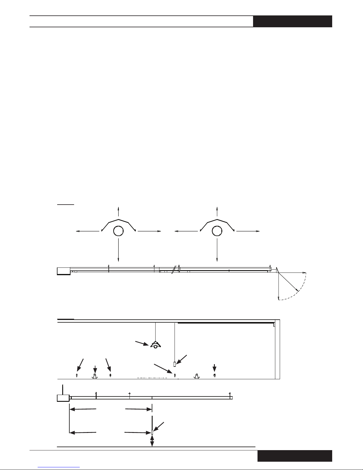
(ft.) See Fig. 1 on
page 5.
To p 1
Sides 2.5 6
Discharge End 6
Below radiant tubes 5 6
Temperature
sensor location
See Fig. 2 on page 5 of the owner’s manual
CSA-US Approval -
✓
-
Oval 80 v.2 and Sentinel v.2 Radiant Tube Heaters
Owner’s Manual • Oval 80 v.2 and Sentinel v.2
5
DESPERDICIOS
SENSOR IN PROXIMITY
TO AN INSIDE WATER LINE
DE 12"
A 18"
This owner’s manual includes all options and accessories commonly used on or with this heater.
However, depending on the confi guration purchased,
some options and accessories may not be included.
When calling for technical service assistance, or for
other specifi c information, always have the model
number and serial number available.
This manual will instruct you in the operation and
care of your radiant heater. Have your qualifi ed
installer review this manual with you so that you fully
understand the heater and how it functions.
The gas supply line installation, and the repair, installation and servicing of the heater requires continuing
General Information
Safe Clearance from Combustibles
Temperature Sensor Location
expert training and knowledge of gas heaters and
should not be attempted by anyone who is not so
qualifi ed. See page 7 for defi nition of the necessary
qualifi cations.
Contact your local L. B. White distributor or the L.B.
White Co., Inc. for assistance, or if you have any
questions about the use of the heater or its application.
The L.B. White Co., Inc. has a policy of continuous
product improvement. It reserves the right to change
specifi cations and design without notice.
FIG. 1
FIG. 2
WATER LINES
INSIDE WATER LINES INSIDE WATER LINES
HEATER
FEED LINE
SENSOR LOCATED DIRECTLY
ABOVE INSIDE WATER LINE AND
12-18 IN. ABOVE LITTER
FEED LINE
ALL SENTINEL OVAL 80
2.5 FT6 FT
6 FT
6 FT
1 FT 1 FT
5 FT
2.5 FT
SENSOR LOCATION FROM BURNER BOX
OVAL 80: 10 FT.
SENTINEL: 15 FT.
LITTER
SENSOR
12-18 IN.
FEED LINE
6 FT
6 FT
6 FT
Oval 80 v.2 and Sentinel v.2 Radiant Tube Heaters
www.lbwhite.com
Owner’s Manual • Oval 80 v.2 and Sentinel v.2
6
Propane gas and natural gas have man-made odorants added specifi cally for detection of fuel gas leaks.
If a gas leak occurs, you should be able to smell the
fuel gas .
THAT’S YOUR SIGNAL TO GO INTO IMMEDIATE
ACTION!
■ Do not take any action that could ignite the fuel
gas. Do not operate any electrical switches. Do not
pull any power supply or extension cords. Do not
light matches or any other source of fl ame. Do not
use your telephone.
■ Get everyone out of the building and away from the
area immediately.
■ Close all propane gas tank or cylinder fuel supply
valves, or the main fuel supply valve located at the
meter if you use natural gas.
■ Propane gas is heavier than air and may settle in
low areas. When you have reason to suspect a
propane leak, keep out of all low areas.
■ Use your neighbor’s phone and call your fuel gas-
supplier and your fi re department. Do not re-enter
the building or area.
■ Stay out of the building and away from the area
until declared safe by the fi refi ghters and your fuel
gas supplier.
■ FINALLY, let the fuel gas service person and the
fi refi ghters check for escaped gas. Have them
air out the building and area before you return.
Properly trained service people must repair the
leak, check for further leakages, and then relight
the appliance for you.
■ Some people cannot smell well. Some people
cannot smell the odor of the man-made chemical added to propane or natural gas. You must
determine if you can smell the odorant in these
fuel gases.
■ Learn to recognize the odor of propane gas and
natural gas. Local propane gas dealers and your
local natural gas supplier (utility) will be more than
happy to give you a “scratch and sniff” pamphlet.
Use it to become familiar with the fuel gas odor.
■ Smoking can decrease your ability to smell. Being
around an odor for a period of time can affect your
sensitivity to that particular odor. Odors present in
animal confi nement buildings can mask fuel gas
odor.
■ The odorant in propane gas and natural gas is col-
orless and the intensity of its odor can fade under
some circumstances.
■ If there is an underground leak, the movement of
gas through the soil can fi lter the odorant.
■ Propane gas odor may differ in intensity at different
levels. Since propane gas is heavier than air, there
may be more odor at lower levels.
■ Always be sensitive to the slightest gas odor. If you
continue to detect any gas odor, no matter how
small, treat it as a serious leak. Immediately go into
action as discussed previously.
Fuel Gas Odor
Safety Precautions
Odor Fading - No
Odor Detected
WARNING
Asphyxiation Hazard
■ Do not use this radiant heater for heating human living quarters.
■ Do not use in unventilated areas.
■ The fl ow of combustion and ventilation air must not be obstructed.
■ Proper ventilation air must be provided to support the combustion air requirements of the heater
being used.
■ Refer to the specifi cation section of the Owner’s Manual, heater’s dataplate, or contact the LB
White Company to determine combustion air ventilation requirements of the heater.
■ Lack of proper ventilation air will lead to improper combustion.
■ Improper combustion can lead to carbon monoxide poisoning in humans leading to serious injury
or death. Symptoms of carbon monoxide poisoning can include headaches, dizziness and diffi culty
in breathing.
■ Symptoms of improper combustion affecting livestock can be disease, lower feed conversion,
or death.

Oval 80 v.2 and Sentinel v.2 Radiant Tube Heaters
Owner’s Manual • Oval 80 v.2 and Sentinel v.2
7
■ Propane gas and natural gas have a distinctive
odor. Learn to recognize these odors. (Reference
“Fuel Gas Odor” and “Odor Fading” sections
above.
■ If you have not been properly trained in repair and
service of propane gas and natural gas fueled
heaters, then do not attempt to light the heater, perform service or repairs, or make any adjustments
to the heater on a propane (LP) gas or natural gas
fuel system.
■ Even if you are not properly trained in the service
and repair of radiant heaters, ALWAYS be consciously aware of the odors of propane gas and
natural gas.
■ A periodic “sniff test” around the heater or at the
heater’s joints; i.e. hose, connections, etc., is a
good safety practice under any conditions. If you
smell even a small amount of gas, CONTACT
YOUR FUEL GAS SUPPLIER IMMEDIATELY.
DO NOT WAIT!
1. Do not attempt to install, repair or service this
heater or the gas supply line unless you have
continuing expert training and knowledge of gas
heaters.
QUALIFICATIONS FOR SERVICING AND
INSTALLATION:
a. To be a qualifi ed gas heater service person, you
must have been trained in gas-fi red heater servic-
ing, repair and also have suffi cient experience to
allow you to troubleshoot, replace defective parts,
and test heaters in order to get them into a continuing safe and normal operation condition. You must
completely familiarize yourself with each model
heater by reading and complying with the safety
instructions, labels, owner’s manual, etc. that is
provided with each heater.
b. To be a qualifi ed gas installation person, you must
have suffi cient training and experience to handle
all aspects of installing, repairing and altering gas
lines, including selecting and installing the proper
equipment, and selecting proper pipe size to be
used. This must be done in accordance with all
local, state and national codes as well as the
manufacturer’s requirements.
2. All installations and applications of L.B. White heaters must meet all relevant local, state and national
codes. Included are L.P. gas, electrical, and safety
codes. Your local fuel gas supplier, a local licensed
electrician, the local fi re department or similar
government agencies, or your insurance agent can
help you determine code requirements.
-- ANSI/NFPA 58, latest edition, Standard for Storage
and Handling of Liquefi ed Petroleum Gas and/or
-- ANSI Z223.1/NFPA 54, National Fuel Gas Code
-- ANSI/NFPA 70, National Electrical Code.
3. For indoor installation only in agricultural poultry
confi nement buildings. Not for use in residential
dwellings.
4. Do not move, handle, or service heater while in
operation or connected to a power or fuel supply.
5. This heater may be installed in areas subject to
washdown. This heater may only be washed on the
external components. See Cleaning Instructions.
Do not wash the interior of the burner box or the
tubes. Use only compressed air, soft brush or dry
cloth to clean the interior of the heater and it’s components. After external washdown, do not operate
this heater until it is completely dry. In any event,
do not operate the heater for at least one hour after
external washdown.
6. For safety, this heater is equipped with an differential air pressure switch. Never operate this
heater if this safety device has been bypassed. Do
not operate this heater unless this feature is fully
functioning.
7. The heater is designed to operate only with its
burner access door closed and latched. Do not
operate the heater with its burner box access door
open.
8. Do not block air intakes or discharge outlets of the
heater. Doing so may cause improper combustion or damage to heater components leading to
property damage or animal loss.
Attention - Critical
Points to Remember!

Oval 80 v.2 and Sentinel v.2 Radiant Tube Heaters
www.lbwhite.com
Owner’s Manual • Oval 80 v.2 and Sentinel v.2
8
9. The hose assembly shall be visually inspected on
an annual basis. If it is evident there is excessive
abrasion or wear, or if the hose is cut, it must be
replaced prior to the heater being put into operation. The hose assembly shall be protected from
animals, and contact with hot surfaces during use.
The replacement hose assembly shall be that
specifi ed by the manufacturer. See parts list.
10. Check for gas leaks and proper function upon
heater installation and before building repopulation.
11. This heater should be inspected for proper
operation by a qualifi ed service person at least
annually.
12. Always turn off the gas supply to the heater
when not in use.
13. This heater is equipped with a three-prong
(grounding) plug for your protection against
shock hazard and must be plugged directly into
a properly grounded three-prong receptacle.
Failure to use a properly grounded receptacle
can result in electrical shock, personal injury, or
death.
14. Direct ignition heaters will make up to three trials
for ignition. If ignition is not achieved, the control
system will lock out the gas control valve. If gas
is smelled after system lock out has occurred,
immediately close all fuel supply valves. Do not
relight until you are sure that all gas that may
have accumulated has cleared away. In any
event, do not relight for at least 5 minutes.
15. Use only approved gas hose or approved fl exible
connectors which are rated for use with propane
or natural gas.
Oval 80 v.2 and Sentinel v.2 Radiant Tube Heaters
Owner’s Manual • Oval 80 v.2 and Sentinel v.2
9
WARNING
Combustion Hazard
■ Provide a properly located and sized fresh air
inlet for the heater.
-- Refer to Inlet Air Requirements instructions.
■ Failure to provide a fresh air inlet can lead to:
-- Sooting causing building damage
-- High carbon monoxide levels, causing serious
injury or death to livestock and humans.
-- Overheating of the fi rst 10 ft. tube, causing
fi res leading to building damage and injury to
livestock and humans.
-- Higher temperature differences over the length
of the tubes, causing problems in temperature
control and bird performance
Inlet Air Requirements
This heater requires clean, fresh air from a normal,
atmospheric pressure environment for proper operation and combustion. Contact L.B.White Company if
you have any questions regarding the installation of
this heater.
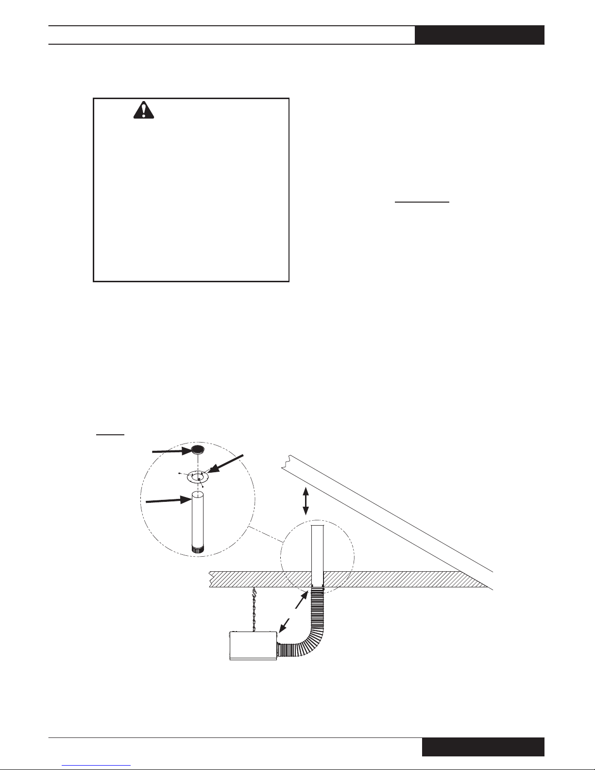
Inlet air may be drawn from the attic or through side
walls under a protective eve. See Figs. 3 and 4.
-- All inlet air seams and joints must be sealed
-- Do not use any fi lters on the air inlet system
-- The air inlet system must be kept as
straight as possible. No more than 1 90º bend is allowed.
-- Contact L.B.White Co. if you have any questions
regarding the installation of the heater.
Inlet air for combustion MUST NOT be drawn
from:
■ Inside the confi nement room.
■ An attic or location where negative pressure
(vacuum) affects the air draw of the heater’s fan.
Examples include, but are not limited to:
a. Houses with attic soffi t vent area smaller than
ridge cap vent area
b. Heater air inlet located within 20 ft. of building
ventilation fans
c. Locations where wind and/or the elements can
create a negative pressure.
FIG. 3
Vent Cap
Air inlet
tube
Ceiling
fl ange
12 in. from
inside of
roof
A. Slide fl ange down
air inlet tube until
it meets bevel in
tube.
B. Attach fl ange to
tube using three
self drilling screws.
C. Firmly push vent
cap with screen
into tube.
Cut 4-1/4 in. hole in ceiling adjacent to
joist. Spread insulation away and fasten
ceiling fl ange to joist.
Flex tube: Cut to length
-- Do not exceed 4 ft. max. length
-- Do not kink (part #573382)
Inlet tube must be
12 in. min.
above insulation
Ensure inlet cap is
unblocked by insulation.
DRAWING INLET AIR FROM ATTIC
Clamps
Oval 80 v.2 and Sentinel v.2 Radiant Tube Heaters
www.lbwhite.com
Owner’s Manual • Oval 80 v.2 and Sentinel v.2
10
1. Read all safety precautions and follow L.B. White
recommendations when installing this heater. If during
the installation of the heater, you suspect that a part is
damaged or defective, call a qualifi ed service agency
for repair or replacement.
2. A qualifi ed service agency must check the heater upon
installation and periodically. This shall consist of the
following:
-- Start up and shut down of the heaters to test for proper
operation.
-- Leak check all gas pipe joints and gas hose
connections.
-- Gas pressure checks.
-- Ensuring the heater is properly positioned away from
combustible materials.
3. Heater installation must take into consideration proper
hanging height to allow for clearance of catching machines, litter spreaders, and any other equipment used.
INSTALLATION INSTRUCTIONS
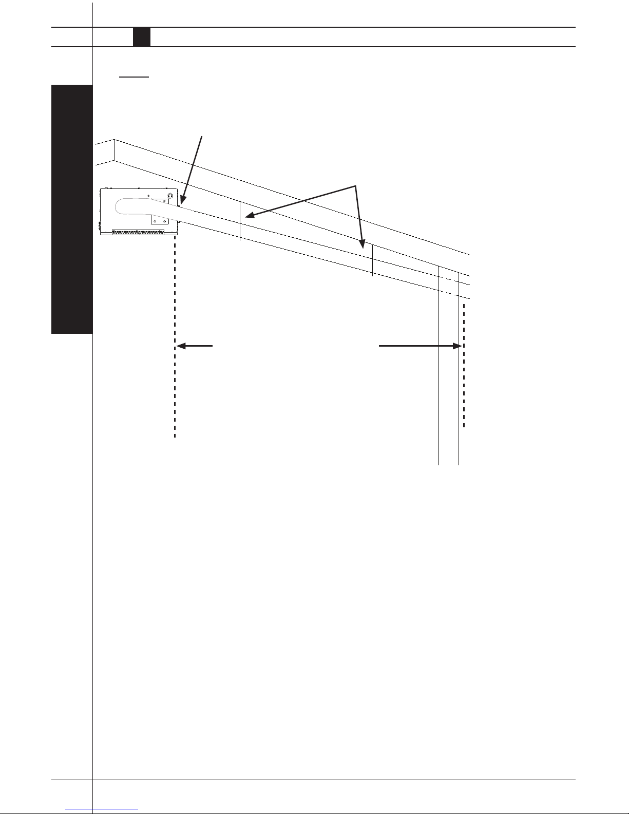
FIG. 4
DRAWING INLET AIR THROUGH SIDEWALLS
General Installation Instructions
4. Ensure the heater installation does not interfere with water, gas, or electrical lines.
5. Position the gas hose to prevent any contact
with the tubes, heat refl ectors, and burner
box.
6. Ensure that all accessories that ship with the
heater have been removed from shipping
containers and installed. This pertains to gas
hose, regulators, supports, hangers, etc.
7. This heater requires a regulated gas supply
to its gas inlet :
-- The regulator must be the proper design for
the
application.
-- The regulator must control the inlet pressure
to the heater within the range specifi ed on the
dataplate.
Use minimum length of 4 in. diameter fl ex duct when connecting 4 in. PVC to
burner box. An adapter connection for the burner box to the 6 in. PVC must be
obtained through local source.
Install supports every 5 ft. to prevent inlet sagging
Secure inlet to wall
For inlet runs up to 20 ft., use smooth
4 in. iD PVC. For runs over 20 ft.,
use 6 in. ID PVC
Air inlet use
inlet cap,
24861 for 4
in. PVC. Can
also use 1/4 x
1/4 hardware
cloth for either
4 in. or 6 in.
PVC
Do not locate the heater’s air inlet by
any building air inlet.
Air inlet
Oval 80 v.2 and Sentinel v.2 Radiant Tube Heaters
Owner’s Manual • Oval 80 v.2 and Sentinel v.2
11
-- Regulators mounted outside must be protected from
adverse weather conditions.
-- Regulators with pressure relief valves should be
installed outside the building.
-- Regulators installed inside should be vented outside.
-- Local state and national codes apply to regulator in-
stallation. Refer to NFPA 54, National Fuel Gas Code,
and NFPA 58, Standard for Storage and Handling of
Liquifi ed Petroleum Gas.
8. Always use pipe joint compound that is resistant to
liquefi ed petroleum gas and natural gas.
9. Check all connections for gas leaks using approved
gas leak detectors. Gas leak testing is performed as
follows:
-- Check all pipe connections, hose connections, fi ttings
and adapters upstream of the gas control with approved gas leak detectors.
-- In the event a gas leak is detected, check the compo-
nents involved for cleanliness and proper application of
pipe compound before further tightening.
-- Tighten the gas connections as necessary to stop the
leak.
-- After all connections are checked and any leaks are
stopped, turn on the main burner.
-- Stand clear while the main burner ignites to prevent
injury caused from hidden leaks that could cause
fl ashback.
-- With the main burner in operation, check all connec-
tions, hose connections, fi ttings and joints as well as
the gas control valve inlet and outlet
-- If a leak is detected, check the components involved
for cleanliness in the thread areas and proper application of pipe compound before further tightening.
WARNING
Fire and Explosion Hazard
■ Do not use open fl ame (matches, torches,
candles, etc.) in checking for gas leaks.
■ Use only approved leak detectors.
■ Failure to follow this warning can lead to fi res
or explosions.
■ Fires or explosions can lead to property
damage, injury or death.
-- Tighten the gas connection as necessary to stop the
leak.
-- If necessary, replace the parts or components involved
if the leak cannot be stopped.
-- Ensure all gas leaks have been identifi ed and repaired
before proceeding.
10. Install a sediment trap at the gas valve inlet to prevent
foreign materials (pipe compound, pipe chips and
scale) from entering the gas valve. Debris blown into
the gas valve may cause that valve to malfunction
resulting in a serious gas leak that could result in a
possible fi re or explosion causing loss of products,
building or even life. A properly installed sediment trap
will keep foreign materials from entering the gas valve
and protect the safe functioning of that important safety
component.
11. Any heater connected to a piping system must have an
accessible, approved manual shut off valve installed
within six feet (6 ft.) of the heater it serves.
12. Install the proper size of gas supply line to assure
proper functioning of the heaters. Consult your fuel
gas supplier, or the L.B. White Co., Inc. for proper line
sizing and installation.
13. Light according to instructions on heater or within
Owner’s Manual.
14. The heater is designed for L.P. vapor withdrawal or
natural gas only. Do not use this heater in a propane
liquid withdrawal system. Do not permit propane in
liquid form to enter the heater.
15. The corrosive atmosphere present in animal confi ne-
ment buildings can cause component failure or heater
malfunction. The heater should be periodically inspected and cleaned in accordance with the Maintenance
and Cleaning Instructions in this manual. Make sure
that livestock is protected by a back up alarm system
that limits high and low temperatures and also activates
appropriate alarms.
16. Take time to understand how to operate and maintain
the heater using the owner’s manual. Make sure you
know how to shut off the gas supply to the building and
to the heater. Contact your gas supplier if you have any
questions.
17. Any defects found in performing any of the service
procedures must be eliminated and defective parts
replaced immediately. Retest the heater before placing
it back into service.
Oval 80 v.2 and Sentinel v.2 Radiant Tube Heaters
www.lbwhite.com
Owner’s Manual • Oval 80 v.2 and Sentinel v.2
12
1. Plan the installation. Determine location for the heater
to optimize its heat pattern, keeping in mind cooler
regions in the house (end walls, and curtains) and
clearances to combustibles.
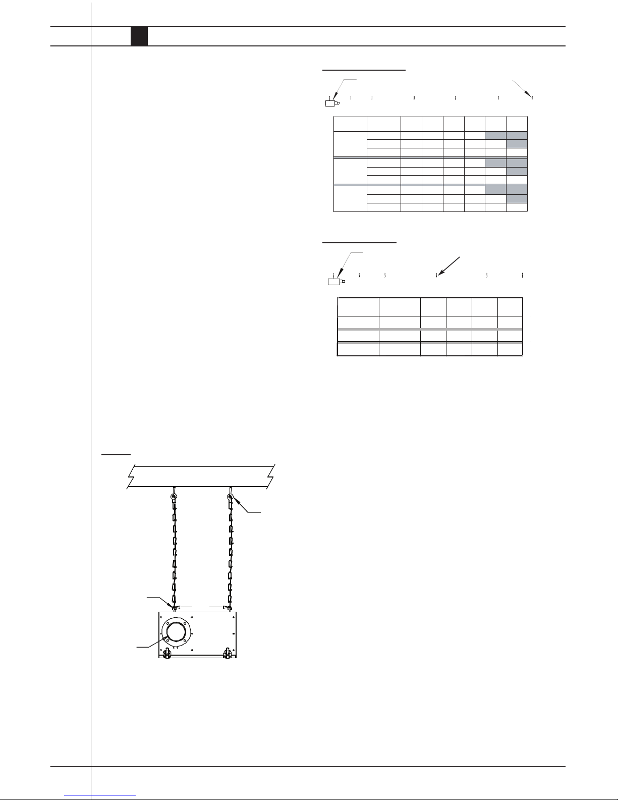
2. Hang the burner box. See Fig. 5. Maintain clearances
to combustibles as shown in Fig. 1.
3. From the burner box chain, measure the distances
shown in Fig. 6 or 7 depending on if a Sentinel or
Oval 80 heater is being installed. Aligning to the
center of the burner box discharge, hang
chains at these points, using open eye hooks.
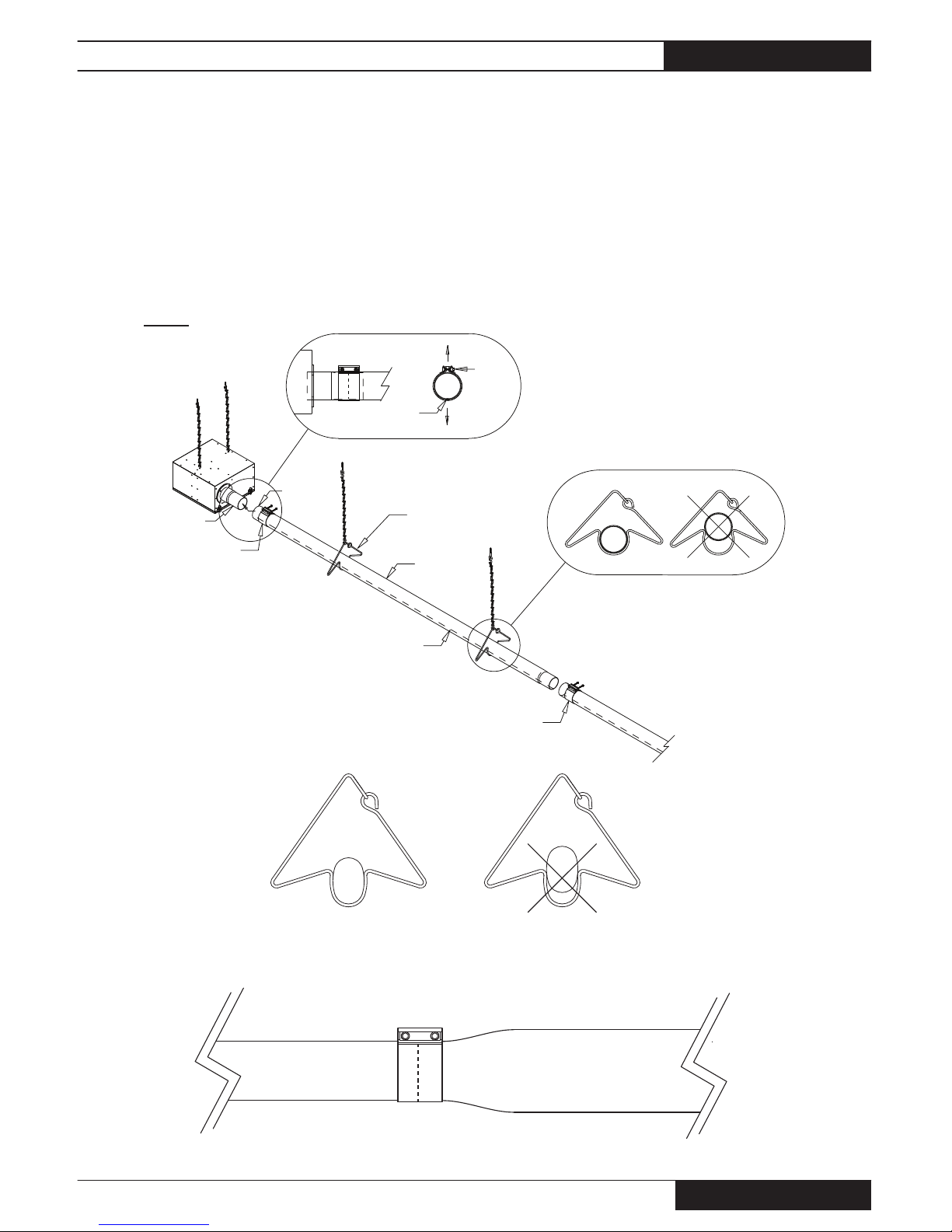
Refer to Fig. 8 (on next page) and the following instructions:
1. Slide a tube clamp over the non-swaged end of the 10 ft.
bright aluminized tube. One aluminized tube per tube kit.
2. Install the tube over the swaged discharge tube on the
burner box:
a. Tube weld seam must be down.
b. Non-swaged end of tube must be complete-
ly pushed over swaged end of adjoining
tube.
c. Clamp must be centered over tube
connection.
d. Clamp bolts must be up.
e. Clamp bolts must be tight.
-- Tighten both bolts fi rmly.
-- Tighten both bolts to 35 ft.-lbs.
-- Finish tightening bolts:
-- Sentinel Heaters: Finish tightening bolts
to 65 ft. lbs.
-- Oval 80 Heaters: Finish tightening bolts
to 44-59 ft. lbs.
Initial Setup
FIG. 5
FIG. 6 SENTINEL
FIG. 7 OVAL 80
JOIST
OPEN EYE HOOKS
IN LINE WITH
EYE BOLTS ON
BURNER BOX
OPEN EYE BOLT
.30m
BURNER
DISCHARGE
TIGHTEN HOOKS
SECURELY
Hanging the Tubes
A
B
C
D
E
HEATER
LENGTH
TRUSS
CENTERS
A - B
B - C C - D D - E
4 FOOT
50 FOOT
4
4
12
8
5 FOOT
50 FOOT
5
5
10
10
10 FOOT
50 FOOT
5
5
10
10
*
* A SUPPORT MUST BE CREATED BETWEEN THE TRUSS
BURNER BOX
HANGING CHA
HANGING CHAIN DISTANCES
(FT)
(FT)
(FT) (FT)
HANGING CHAINS
BURNER BOX
20 FOOT
20 FOOT
20 FOOT
4
4
4
8
5
5
5
5
5
5
5*
5*
F
A
B
C
D
E
F
G
HEATER
LENGTH
TRUSS
CENTERS
A - B
B - C C - D D - E
E - F F - G
4 FOOT
30 FOOT
40 FOOT
50 FOOT
4
4
4
4
4
4
12
12
12
8
8
8
12
12
8
5 FOOT
30 FOOT
40 FOOT
50 FOOT
5
5
5
5
5
5
10
10
10
10
10
10
5
10
5
10 FOOT
30 FOOT
40 FOOT
50 FOOT
5
5
5
5
5
5
10
10
10
10
10
10
5
10
5
*
*
*
*
*
* A SUPPORT MUST BE CREATED BETWEEN THE TRUSSES
BURNER BOX
HANGING CHAINS
HANGING CHAIN DISTANCES
(FT)
(FT)
(FT) (FT) (FT) (FT)
1Ft.
18. Do not exceed input rating stamped on the
dataplate of the heater. Do not exceed the burner
manifold pressure stated on the dataplate. Do
not use an orifi ce size different than specifi ed for
the specifi c input rating of this heater, fuel type
confi guration and altitude.
Oval 80 v.2 and Sentinel v.2 Radiant Tube Heaters
Owner’s Manual • Oval 80 v.2 and Sentinel v.2
13
FIG. 8
CLAMP
SWAGED TUBE
ON BOX
NON-SWAGED
TUBE END
HANGER
CLAMP
BOLTS UP
TUBE WELD
SEAM DOWN
BRIGHT
ALUMINIZED
TUBE
TUBE WELD SEAM
CLAMP
THIS NOT THIS
ROUND TUBE HANGER INSTALLATION - SENTINEL AND OVAL 80
POSITION CLAMP
EVENLY
CLAMPS MUST BE CENTERED OVER
SWAGED AND NON-SWAGED ENDS OF
TUBES
OVAL 80 HE ATERS
OVAL TUBE HANGERS
ROUND TUBE TO OVAL TUBE CLAMP INSTALLATION
3 IN. ROUND CLAMP (CENTERED WITH BOLTS UP)
3 IN. ROUND TUBE
OVAL TUBE
THIS
NOT THIS
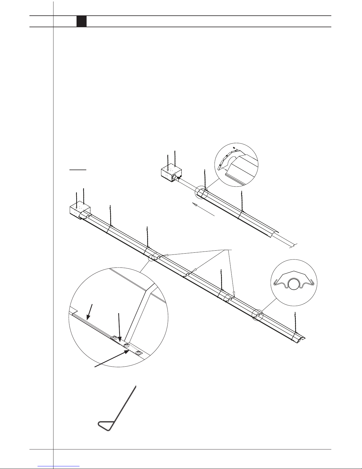
3. Slide on hangers and connect to chains.
4. Connect and hang remaining tubes. Follow the procedures
given in Step 2.
5. The tube assembly should be either hung level, or
with a downward slope away from the burner box not
exceeding 1 in. for every 10 ft. of tube.
Oval 80 v.2 and Sentinel v.2 Radiant Tube Heaters
www.lbwhite.com
Owner’s Manual • Oval 80 v.2 and Sentinel v.2
14
SUPPORTS
FIG. 9
CONNECTION STRIPS:
• Insert a connection strip halfway
into the folded channel at both
sides of a refl ector, at the end
without fl anges.
• Slide this end of the refl ector
through the hanger and push it
fi rmly into the folded channels of
the refl ector at the burner box.
• The unfl anged end of the refl ector
will overlap the fl anged end of the
adjacent refl ector.
FLANGE
OVERHEAD
SUPPORT
CONNECTOR STRIP
(DIMPLES UP)
Refer to Fig. 9 and the following instructions:
1. Slide the refl ector through the hangers until it is
about 1 or 2 inches away from the burner box.
2. Attach end cap to end of this refl ector.
Use 4 U-clips. Push this refl ector up to burner box.
3. Sentinel Heaters Only: Install a support at end of
refl ector nearest burner box and at middle and
ends of all refl ectors. Do not install a support
directly next to a hanger on the same refl ector.
Installing Reflectors & Supports
4. Connect the refl ectors using the dimpled con-
nector strips. See below.
5. Repeat Steps 3 and 4 for remaining refl ectors.
6. Attach remaining end cap to last refl ector with
U-clips.
REFLECTOR END VIEW
SHOWING FOLDED
CHANNEL
DOTTED LINES: INDICATE
CONNECTOR WITHIN FOLDED
CHANNEL
Oval 80 v.2 and Sentinel v.2 Radiant Tube Heaters
Owner’s Manual • Oval 80 v.2 and Sentinel v.2
15
REGULATOR
NIPPLE
VALVE, MANUAL
SHUT-OFF
GAS HOSE
ADAPTER
SEDIMENT TRAP
TO CONTROL
VALVE INLET
REGULATOR VENT
GAS FLOW
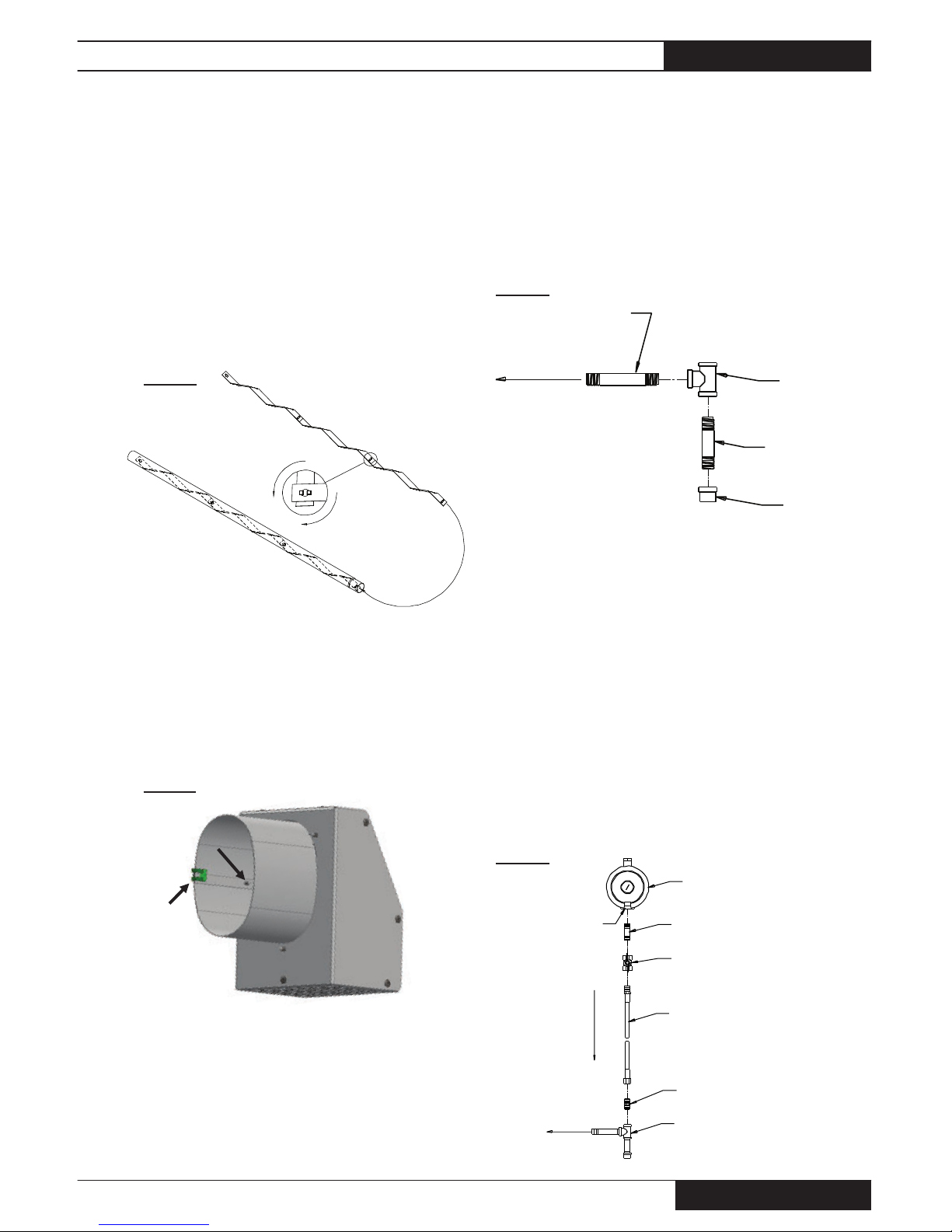
SENTINEL HEATERS: Assemble the strips and insert
into last tube, see Fig. 10. Edge of strip is fl ush with
end of tube.
OVAL 80 HEATERS: Both strips are
factory installed into the oval tube. At
installation, ensure strips are snugly fi t
into oval tube and do not extend past
end of tube.
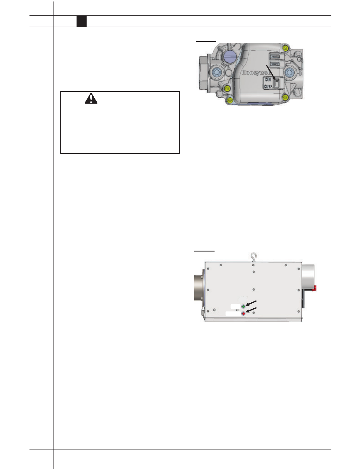
Assemble the tee, nipple, and cap to the nipple at the
gas inlet of the heater. See Fig. 12. Use a wrench to
hold the pipe nipple when installing the sediment trap.
Tighten securely. The sediment trap assembly must
always be mounted in a vertical position. Check all
connections for gas leaks using approved gas leak
detectors.
1. Assemble the components together. See Fig. 13.
This view shows general assembly of the components. The regulator must always be mounted so its
vent, regardless of location on the regulator, is always pointed downward. Ensure hose is positioned
away from the heater.
2. Tighten all connections securely and check
for gas leaks
Air Turbulation Strips
& Vent
Sediment Trap Assembly
Manual Shut-off Valve,
Hose & Regulator
FIG. 10
FIG. 12
FIG. 13
FIG. 11
NIPPLE
TEE
NIPPLE
CAP
OUTLET END
TO GAS CONTROL VALVE INLET
INSERT STRIP ASSEMBLY
INTO LAST 10 FT. OF TUBE
GREEN
CLIP
REGARDLESS OF TUBE DESIGN:
-- Ensure the green clip is installed on the exhaust vent.
See Fig. 11.
-- Insert the exhaust vent to the end of the last tube.
-- Push the exhaust vent until the tube is stopped at
the rivet.
Oval 80 v.2 and Sentinel v.2 Radiant Tube Heaters
www.lbwhite.com
Owner’s Manual • Oval 80 v.2 and Sentinel v.2
16
Heater Controls
Refer to the heater’s burner box hinged access panel, or
refer to Start-up instructions in this manual to determine if
your heater has a single or two stage gas control.
The tube heater is operated by the building’s environmental control system. To accomplish this, the heater must be
connected to an electrical outlet controlled by a relay or
set of contacts that is closed and opened by the building
controller.
A series tap thermostat may be used to operate the tube
heater.
Connecting a Series Tap
Thermostat
-- Connect the power cord of the heater to the female side
of the thermostat cord set.
-- Plug the male side of the thermostat cord to an approved extension cord or to a wall outlet.
Start-Up Instructions
Follow steps 1 - 6 on initial start-up after heater installation. For normal start-up, set building control thermostat
above room temperature. The heater will start.
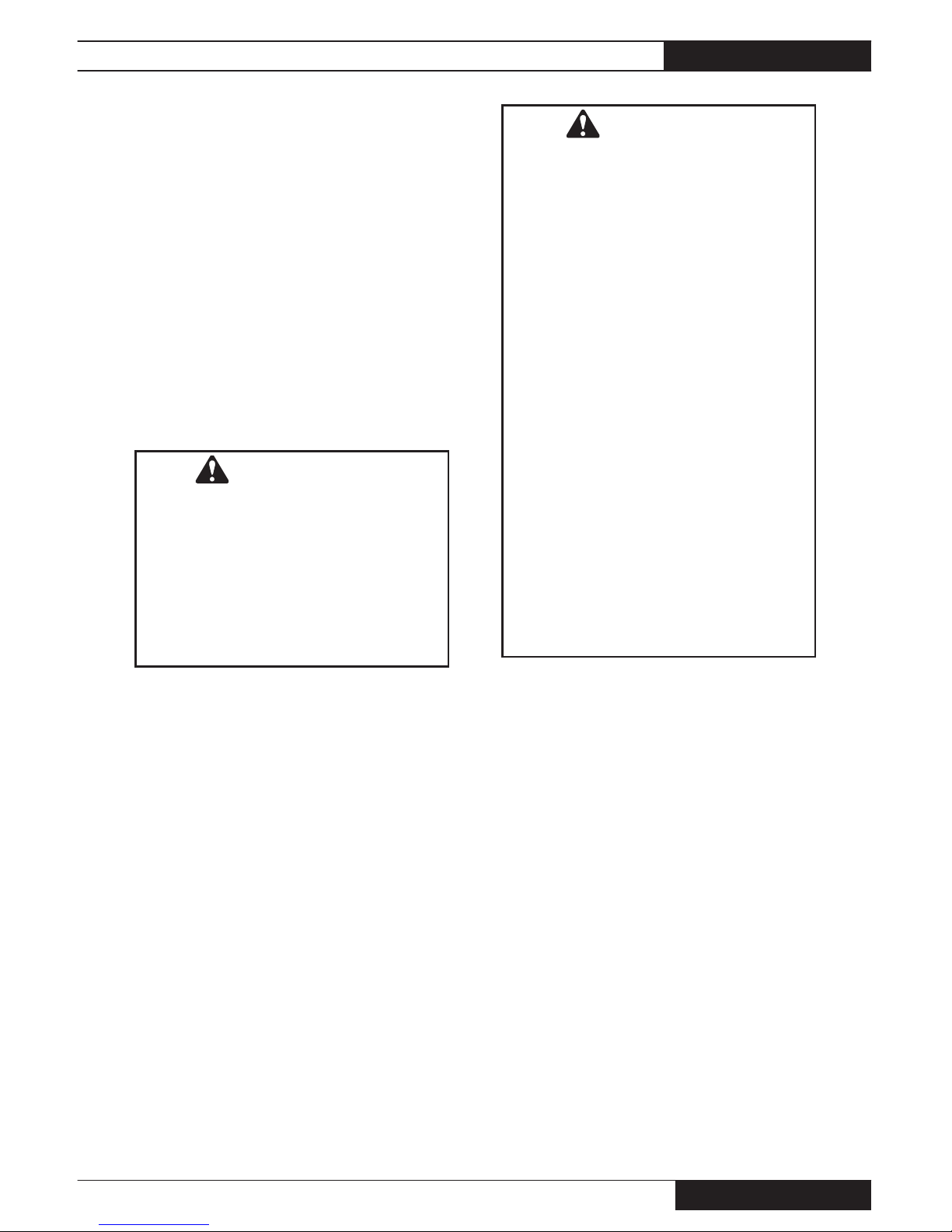
1. Open all manual fuel supply valves and check for gas
leaks using approved leak detectors. The gas control
valve has a manual shut-off feature incorporated into
the valve assembly. Ensure the indicator on the valve
is turned to the ON position. See Fig. 14.
WARNING
Electrical Shock Hazard
■ Disconnect the heater’s electrical supply before
interconnecting the temperature control.
■ Failure to disconnect the electrical supply will
result in electrical shock.
■ Electrical shock will cause severe injury or
death.
2. Connect the electrical cord to an approved electrical outlet.
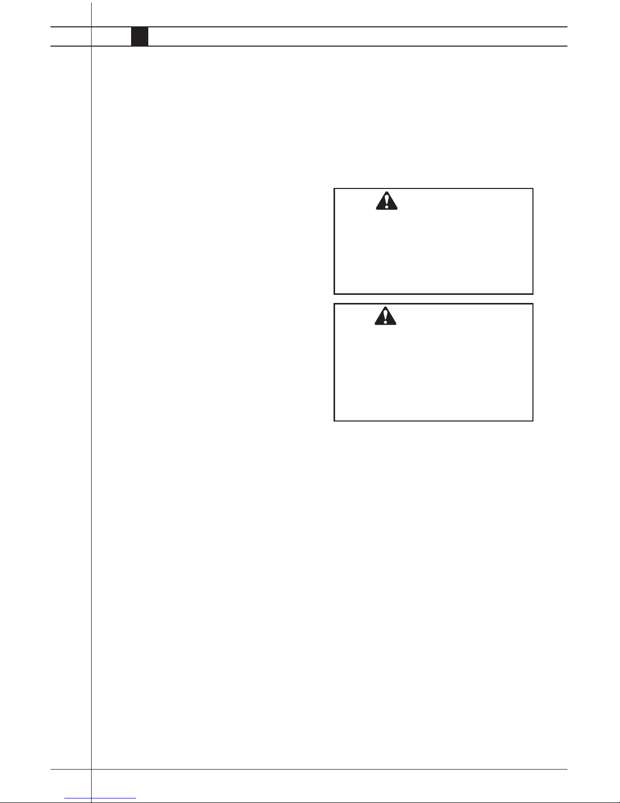
3. This heater includes a direct ignition control
module for purposes of controlling the timing of the
ignition process of the heater as well as monitoring
of the safety functions. A red FAULT LED (light
emitting diode) is on the burner box. A fl ash-
ing red light identifi es a problem in
the operation of the heater. Refer to the
troubleshooting decal on the interior of the access
panel for assistance in troubleshooting.
4. On a call for heat, the ON green light will be lit and
the motor will start up and run for fi ve (5) seconds.
See Fig. 15.
FIG. 15
GREEN
RED
ON
FAU LT
5. This pre-purge is a safety feature and a normal
operational characteristic prior to ignition taking
place. After fi ve (5) seconds, the igniter will spark.
6. The ignition control will make up to three trials for
ignition. Each trial for ignition will take approximately ten seconds. If the main burner does not
light, the system will lock out, and a three fl ash
pattern will be given by the red LED.
NOTE: It is normal for air to be trapped in the gas
hose on new installations. The heater may try more
than once for ignition before the air is fi nally purged
from the line and ignition takes place.
FIG. 14
Oval 80 v.2 and Sentinel v.2 Radiant Tube Heaters
Owner’s Manual • Oval 80 v.2 and Sentinel v.2
17
Shut-Down Instructions
If the heater is to be shut down for cleaning, maintenance or repair, follow steps 1 - 4. Otherwise, set the
thermostat to off or no heat for standard shut down.
1. Close all manual fuel supply valves.
2. With the heater lit, allow heater to burn off excess
fuel in gas supply hose.
3. Turn thermostat to off or no heat position.
4. Disconnect the heater from the electrical supply
Cleaning Instructions
1. Before cleaning, close the fuel supply valve to the
heater and disconnect the electrical supply. Allow
heater to cool.
2. The heater should have dirt or dust removed
periodically:
a. After each fl ock or between building re-popula-
tion, give the heater a general cleaning using
pressurized air or a soft brush on its burner box,
refl ectors, and tubes.
b. At least once a year, give the heater a thorough
cleaning. At this time, open the burner box and
brush or blow off control components, and fan
motor assembly. Ensure the burner air inlet
venturi ports and the throat of the casting are
free of dust accumulation.
c. When washing with water, do not spray water
into the burner box or the tubes. Observe and
obey the Warning within these Cleaning Instructions. This same Warning is supplied on the
heater.
WARNING
Fire, Burn and Explosion Hazard
■ This heater contains electrical and mechanical
components in the gas management, safety and
airfl ow systems.
■ Such components may become inoperative or
fail due to dust, dirt, wear, aging, or the corrosive
atmosphere of an animal confi nement building.
■ Periodic cleaning and inspection as well as
proper maintenance are essential to avoid serious injury or property damage.
WARNING
This heater may be washed only on its external
areas provided:
■ The burner box is disconnected from the electri-
cal supply.
■ The burner box access panel is closed and
securely latched.
■ Water spray nozzle shall not discharge within 6
feet of the burner box and its tubes.
■ The water pressure does not exceed 45 PSIG
for 10 seconds on each side of burner box.
■ The burner box is not reconnected to electrical
supply for a minimum of 1 hour or until the it is
thoroughly dry.
Improper cleaning can cause severe personal
injury or property damage due to water and/or
cleaning solution:
■ In electrical components, connections and wires
within the burner box causing electrical shock or
component failure.
■ On gas control components causing corrosion
which can result in gas leaks and fi re or explo-
sion from the leak.
Clean internal components of the burner box with a
soft, dry brush or cloth, or compressed air.
Oval 80 v.2 and Sentinel v.2 Radiant Tube Heaters
www.lbwhite.com
Owner’s Manual • Oval 80 v.2 and Sentinel v.2
18
Maintenance Instructions
Before Each Use:
1. Check to make sure the heater’s surrounding area
is kept clear and free from combustible materials,
gasoline, and other fl ammable vapors and liquids.
2. Regulators must be periodically inspected to make
sure the regulator vents are not blocked. Debris,
insects, insect nests, snow, or ice on a regulator
can block vents and cause excess pressure at the
appliance.
3. Check all hose and tubing assemblies for cracks,
cuts, abrasions or ruptures. Replace any hoses that
are suspect.
4. Check all gasketing on burner box and fan housing
discharge. Ensure all is in good condition. Replace
any gasket material if suspect
5. Ensure refl ector supports and hangers are secure,
refl ectors do not sag, and are properly located.
6. Check overall condition of heater for cracked or
damaged components, loose screws or bolts,nicked
or cut electrical leads, etc. Replace any suspect
components.
7. For safety as well as for optimum performance at
the heater, it is necessary to keep the outside of the
heater free of dust, dirt or any combustible material.
If any operational component shows signs of rust or
corrosion, replace the component immediately.
8. Check all warning or instruction labels, dataplates,
etc. If any are lost or become hard to read, replace
them immediately. Do not operate the heater until you
have all instructions and can read and understand
them.
Annually:
1. Check the air inlet assembly. Ensure the air inlet assembly and its duct are free of blockages.
2. Have your gas supplier check all gas piping for leaks
or restrictions in gas lines. Also, at this time have
your gas supplier clean out the sediment trap at the
inlet of the burner box of any debris that may have
accumulated.
3. Regulators can wear out and function improperly.
Have your gas supplier check the date codes
on all regulators installed and check delivery
pressures to the appliance to make sure that the
regulator is suitable for continued use.
General Service
Instructions
1. Close the fuel supply valve to the heater and
disconnect the heater’s electrical supply before
servicing unless it is necessary to have the valve
open and electrical supply connected for your
service procedure.
2. Open the burner box for access to control components. Close and latch after servicing.
3. For reassembly, reverse the respective service
procedure. Ensure gas connections are tightened
securely.
4. Clean the heater’s burner orifi ce and pressure
switch orifi ces with compressed air or a soft,
dry rag. Do not use fi les, drills, broaches, etc. to
clean the orifi ce hole. Doing so will enlarge the
hole, causing ignition or combustion problems.
Replace the orifi ce if it cannot be cleaned
properly.
5. Disconnect appropriate component electrical
leads when servicing. After servicing, light
the heater to ensure proper operation
and check for gas leaks.
WARNING
Burn Hazard
■ Heater surfaces are hot for a period of time after
the heater has been shut down.
■ Allow the heater to cool before performing
service, maintenance, or cleaning.
■ Failure to follow this warning will result in burns
causing injury.
WARNING
Fire and Explosion Hazard
■ Do not disassemble or attempt to repair any
heater components or gas train components.
■ All component parts must be replaced if defects
are found.
■ Failure to follow this warning will result in fi re or
explosions, causing property damage, injury, or
death.
Oval 80 v.2 and Sentinel v.2 Radiant Tube Heaters
Owner’s Manual • Oval 80 v.2 and Sentinel v.2
19
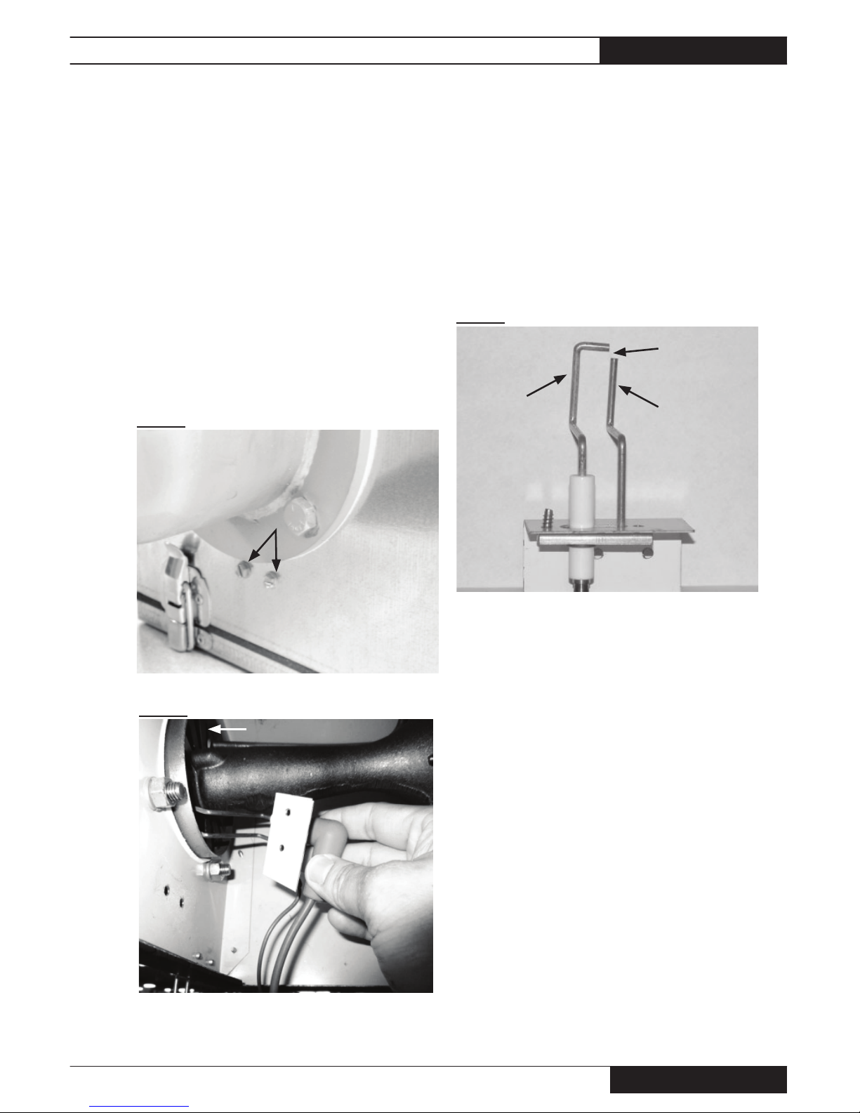
Igniter
The tip of the igniter is exposed to a harsh environment
consisting of high temperatures and combustion products. Periodic servicing is required.
A. REPLACEMENT
1. Remove igniter mounting screws. See Fig. 16.
2. Lift and pivot the igniter until it clears the burner.
See Fig. 17 (Sentinel) for example.
DO NOT FORCE OR BEND THE IGNITER
DURING IGNITOR REMOVAL. DO NOT
FORCE OR BEND THE BURNER VANES
(SENTINEL) DURING IGNITER REMOVAL.
3. Pull the igntion cable’s rubber boot from the igniter.
B. MAINTENANCE
1. Ensure the gap is 1/8 in. See Fig.18.
2. Clean the electrode and ground rod using emery
cloth.
3. Ensure the insulative base of the electrode is not
cracked.
FIG. 16
FIG. 18
SCREWS
ELECTRODE
GROUND ROD
GAP
(1/8 IN.)
FIG. 17
SENTINEL BURNER VANES
Oval 80 v.2 and Sentinel v.2 Radiant Tube Heaters
www.lbwhite.com
Owner’s Manual • Oval 80 v.2 and Sentinel v.2
20
Air Differential Pressure
Switch, Tubing and
Orifices.
Air inlet plate orifi ce:
See Fig. 21. Ensure this orifi ce is free of dust. If the
orifi ce is plugged, remove the two screws that hold
the plate to the burner box. Clean using compressed
air.
FIG. 21
Pressure switch tube: See Fig. 22. Check for
blockage. Clean with compressed air after removing
the tube from the switch and the air inlet plate orifi ce.
FIG. 22
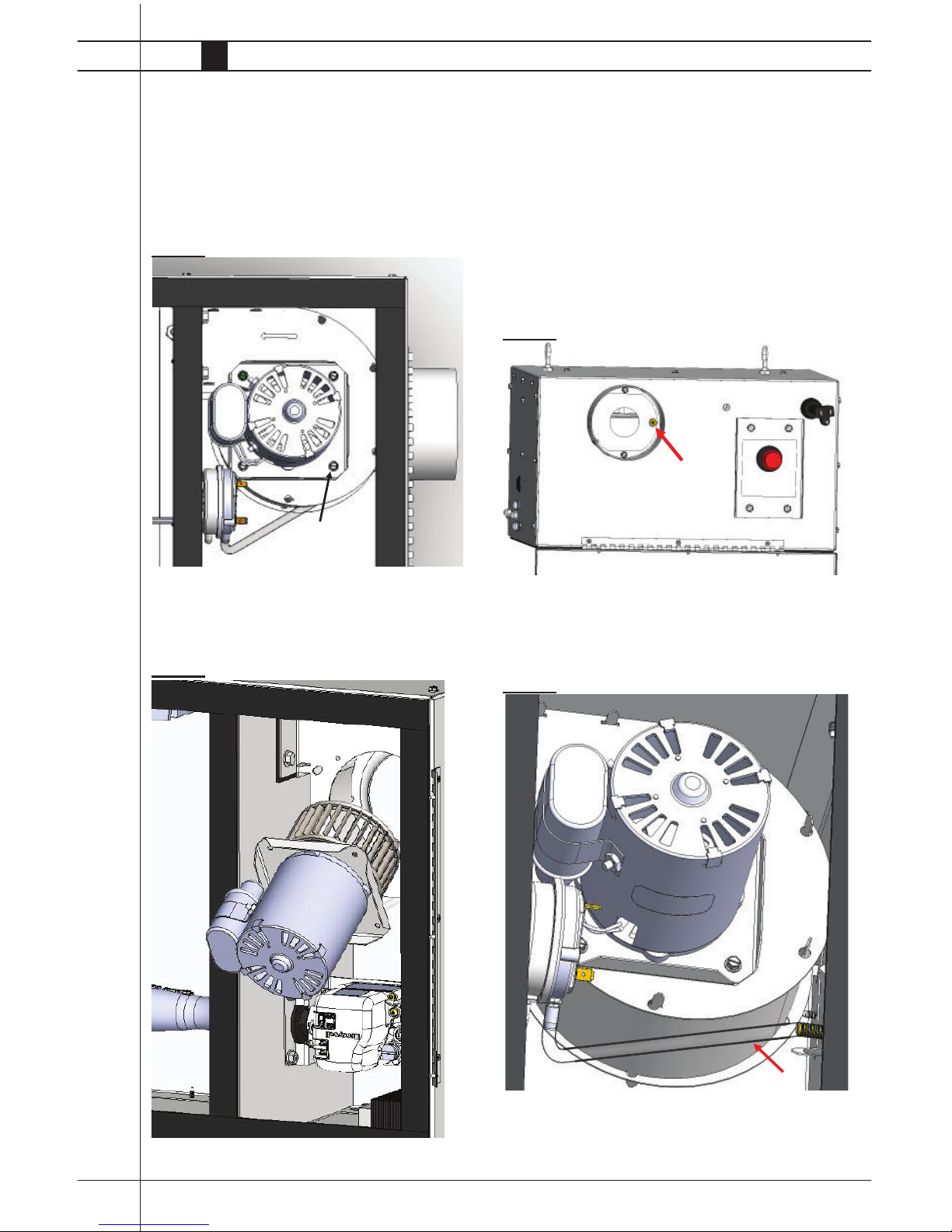
Motor and Fan Assembly
1. Disconnect motor leads.
2. Remove the four (4) motor mounting screws.
See Fig. 19.
FIG. 19
3. Remove motor/fan wheel assembly from fan housing.
See Fig. 20.
FIG. 20
Oval 80 v.2 and Sentinel v.2 Radiant Tube Heaters
Owner’s Manual • Oval 80 v.2 and Sentinel v.2
21
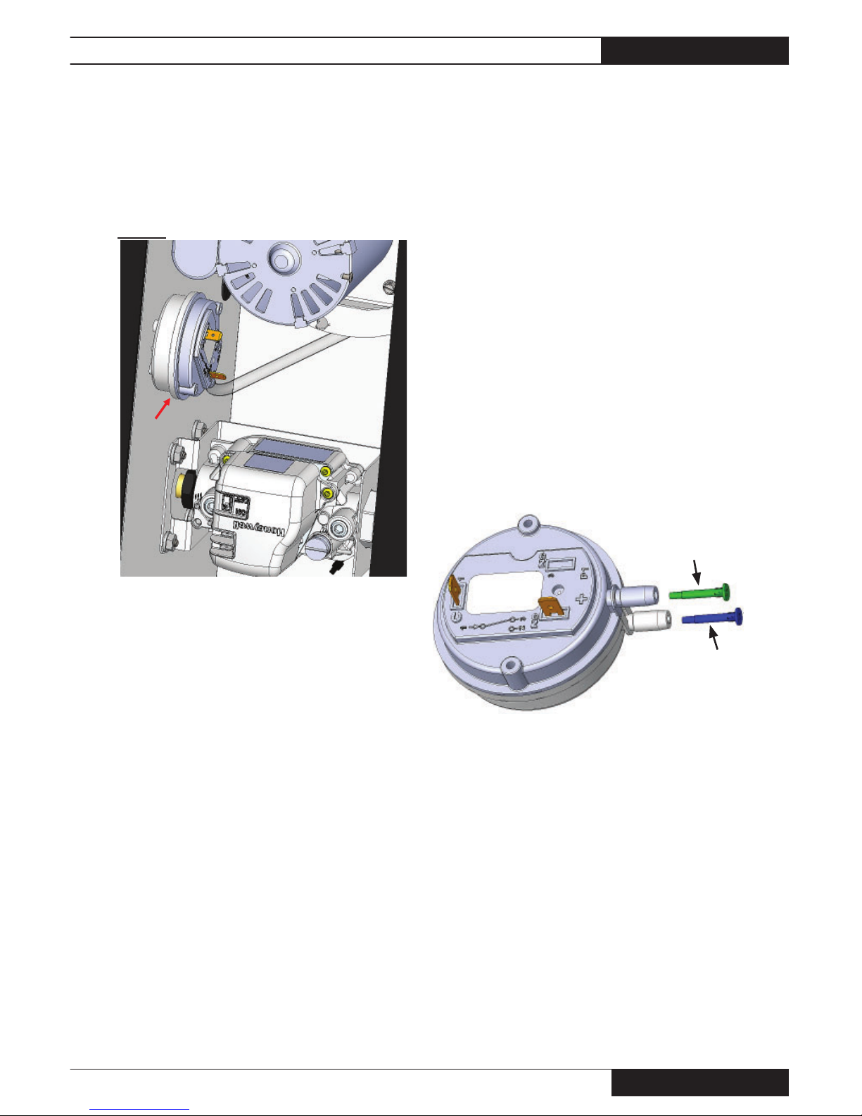
Air diff erential switch:
The air differential switch is a normally open, critical
safety device. See Fig. 23 for location. Its purpose is
to prove to the ignition control that there is a suffi cient
difference in pressure within the burner box before the
ignition control sends power to open the gas control
valve.
FIG. 23
Its electrical contacts close based on the difference
between pressures between the air inlet and the burner
box compartment. If the switch does not close after the
fan motor starts, the igniter will not spark nor will the gas
control valve open. A rapid fl ash will occur on the red
fault diagnostic light. The ignition control will lock-out
for 60 seconds before another trial attempt. After three
(3) fail attempts, a 2-time fl ash pattern will occur. The
same will occur if the fan motor does not start on a call
for heat.
If the switch is already closed from a past ignition trial,
and stays closed prior to a call for heat, the fan motor
will not start, nor will the igniter spark or the valve open.
A rapid fl ash will occur on the red fault diagnostic light.
The ignition control will lock-out for 60 seconds before
another trial attempt. After three (3) failed attempts, a
1-fl ash pattern will occur.
The air differential switch orifi ces should be free of dirt.
If cleaning is needed, use pressurized air. See picture
below.
• Remove the respective orifi ce from the switch.
• Hold up to light. If blocked, clean with air.
• Ensure the orifi ces are pushed back into the proper
location on the switch.
• Green orifi ce into black stem
• Blue orifi ce into white stem on switch.
To test the switch:
• Disconnect the pressure switch wiring at terminals PSI
and PSO of the ignition control.
• Route the wires so both are exterior of the burner box
when the burner box’ access door is closed and latched.
• Start the heater. As soon as the fan motor starts, connect both air switch leads together.
• If the heater starts and operates normally, verify the
following:
o Pressure switch wire terminals at the ignition control
are tight and in good condition.
o No obstructions at air inlet
GREEN
BLUE
Oval 80 v.2 and Sentinel v.2 Radiant Tube Heaters
www.lbwhite.com
Owner’s Manual • Oval 80 v.2 and Sentinel v.2
22
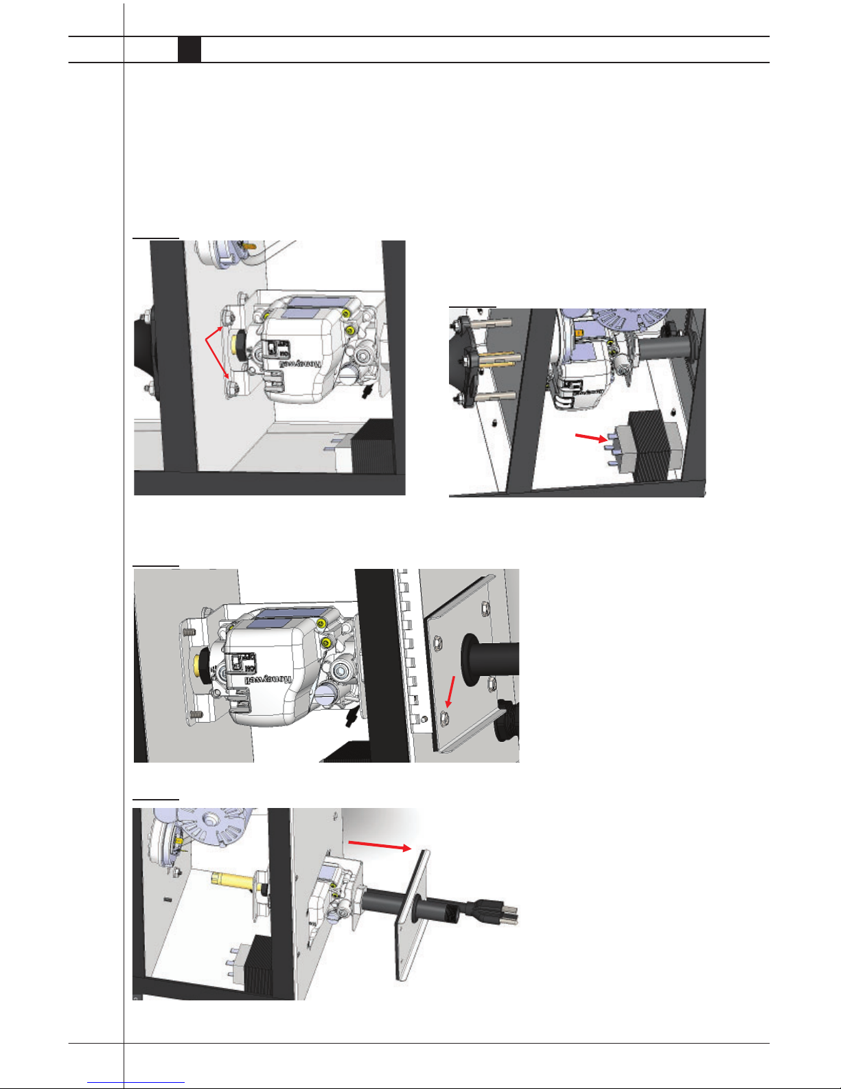
Gas Control Valve
1. Remove the hose from sediment trap.
2. Remove the two nuts that secure the gas control valve’s
mounting bracket to the center partition of the burner
box. See Fig. 24.
FIG. 24
3. Remove the 4 screws from gas valve door. See Fig. 25.
FIG. 25
FIG. 26
4. Pull valve assembly through the gas valve door opening.
See Fig. 26.
Transformer
The transformer (Fig. 27) reduces the main power supply voltage to 24 VAC. The 24 VAC is sent to the ignition
controller. Once the ignition controller receives 24 VAC,
an ignition cycle begins.
If the transformer is receiving main power voltage, but
24 VAC is absent from its output terminals, the transformer is defective. The heater will not operate, nor will
the green LED on the burner box side be on.
FIG. 27
 Loading...