

L.B. White SENTINEL AT 150, SENTINEL AT 125, SENTINEL AT 100 Owner's Manual And Instructions

Owner’s Manual and Instructions
SENTINEL
®
Agricultural Building Radiant Tube Heaters
MODELS OUTPUT (Btuh) FUEL
AT 150 150,000
AT 125 125,000
AT 100 100,000
Propane Vapor
Withdrawal
or
Natural Gas
Congratulations!
You have purchased the finest radiant tube heater available for the heating of
poultry confinement buildings.
Your new L.B. White radiant heater incorporates the benefits from the most
experienced manufacturer of heating products using state-of-the-art technology.
We, at L.B. White, thank you for your confidence in our products and welcome
any suggestions or comments you may have...call us toll free at (800) 345-7200.
ATTENTION ALL USERS
This heater has been tested and evaluated by C.S.A. International in
accordance with the requirements of standard ANSI Z83.20-2008 .CSA
2.34-2008 and is listed and approved as a direct gas-fired radiant tube
heater with intended use for the heating of poultry confinement buildings.
If you are considering using this product for any application other than its
intended use, then please contact your fuel gas supplier, or the
L.B. White Co., Inc.
150-26736
GENERAL HAZARD WARNING
■ Failure to comply with the precautions and instructions provided with this heater, can result in:
—Death
— Serious bodily injury or burns
— Property damage or loss from fire or explosion
— Asphyxiation due to lack of adequate air supply or carbon monoxide poisoning
— Electrical shock
■ Read this Owner’s Manual before installing or using this heater.
■ Only properly-trained service people should repair or install this heater.
■ Save this Owner’s Manual for future use and reference.
■ Owner’s Manuals and replacement labels are available at no charge. For assistance, contact
L.B. White at 800-345-7200.
WARNING
■ Proper gas supply pressure must be provided to the inlet of the heater.
■ Refer to rating plate for proper gas supply pressure.
■ Gas pressure in excess of the maximum inlet pressure specified at the heater inlet can cause
fires or explosions.
■ Fires or explosions can lead to serious injury, death, building damage or loss of livestock.
■ Gas pressure below the minimum inlet pressure specified at the heater inlet may cause
improper combustion.
■ Improper combustion can lead to asphyxiation or carbon monoxide poisoning and therefore
serious injury or death to humans and livestock.
WARNING
Fire and Explosion Hazard
■ Not for home or recreational vehicle use.
■ Installation of this heater in a home or
recreational vehicle may result in a fire or
explosion.
■ Fire or explosions can cause property
damage or loss of life.
FOR YOUR SAFETY
Do not store or use gasoline or other
flammable vapors and liquids in the vicinity of
this or any other heater.
FOR YOUR SAFETY
If you smell gas:
1. Open windows.
2. Don't touch electrical switches.
3. Extinguish any open flame.
4. Immediately call your gas supplier.
WARNING
Improper installation, adjustment, alteration,
service or maintenance can cause property
damage, injury or death. Read the installation,
operating and maintenance instructions
thoroughly before installing or servicing
this equipment.
WARNING
Fire and Explosion Hazard
■ Keep solid combustibles a safe distance
away from the heater.
■ Solid combustibles include wood or paper
products, feathers, straw, and dust.
■ Do not use the heater in spaces which
contain or may contain volatile or airborne
combustibles.
■ Volatile or airborne combustibles include
gasoline, solvents, paint thinner, dust
particles or unknown chemicals.
■ Failure to follow these instructions may
result in a fire or explosion.
■ Fire or explosions can lead to property
damage, personal injury or loss of life.
2

Table of Contents
SECTION
General Information . . . . . . . . . . . . . . . . . . . . . . . . . . . . . . . . . . . . . . . . . . . . . . . . . . . . . . . . . . . . . . . . . . .3
Heater Specifications . . . . . . . . . . . . . . . . . . . . . . . . . . . . . . . . . . . . . . . . . . . . . . . . . . . . . . . . . . . . . . . . . .4
Safety Precautions . . . . . . . . . . . . . . . . . . . . . . . . . . . . . . . . . . . . . . . . . . . . . . . . . . . . . . . . . . . . . . . . . . . .6
Installation Instructions
General . . . . . . . . . . . . . . . . . . . . . . . . . . . . . . . . . . . . . . . . . . . . . . . . . . . . . . . . . . . . . . . . . . . . . . . . .8
Inlet Air Requirements . . . . . . . . . . . . . . . . . . . . . . . . . . . . . . . . . . . . . . . . . . . . . . . . . . . . . . . . . .8
Drawing Inlet Air From Attic . . . . . . . . . . . . . . . . . . . . . . . . . . . . . . . . . . . . . . . . . . . . . . . . . . . . . .8
Drawing Inlet Air Through Side Wall . . . . . . . . . . . . . . . . . . . . . . . . . . . . . . . . . . . . . . . . . . . . . . .8
Initial Set-Up . . . . . . . . . . . . . . . . . . . . . . . . . . . . . . . . . . . . . . . . . . . . . . . . . . . . . . . . . . . . . . . . . . . .10
Hanging the Tubes . . . . . . . . . . . . . . . . . . . . . . . . . . . . . . . . . . . . . . . . . . . . . . . . . . . . . . . . . . . . . . .11
Installing Reflectors & Supports . . . . . . . . . . . . . . . . . . . . . . . . . . . . . . . . . . . . . . . . . . . . . . . . . . . .12
Air Turbulation Strips & Vent Hood . . . . . . . . . . . . . . . . . . . . . . . . . . . . . . . . . . . . . . . . . . . . . . . . . .13
Sediment Trap Assembly . . . . . . . . . . . . . . . . . . . . . . . . . . . . . . . . . . . . . . . . . . . . . . . . . . . . . . . . . .13
Manual Shut Off Valve, Hose & Regulator Assembly . . . . . . . . . . . . . . . . . . . . . . . . . . . . . . . . . . . .13
Heater Controls . . . . . . . . . . . . . . . . . . . . . . . . . . . . . . . . . . . . . . . . . . . . . . . . . . . . . . . . . . . . . . . . . . . . .14
Start-Up Instructions . . . . . . . . . . . . . . . . . . . . . . . . . . . . . . . . . . . . . . . . . . . . . . . . . . . . . . . . . . . . . . . . .15
Shut-Down Instructions . . . . . . . . . . . . . . . . . . . . . . . . . . . . . . . . . . . . . . . . . . . . . . . . . . . . . . . . . . . . . . .15
Cleaning Instructions . . . . . . . . . . . . . . . . . . . . . . . . . . . . . . . . . . . . . . . . . . . . . . . . . . . . . . . . . . . . . . . . .16
Maintenance Instructions . . . . . . . . . . . . . . . . . . . . . . . . . . . . . . . . . . . . . . . . . . . . . . . . . . . . . . . . . . . . .17
Service Instructions
General . . . . . . . . . . . . . . . . . . . . . . . . . . . . . . . . . . . . . . . . . . . . . . . . . . . . . . . . . . . . . . . . . . . . . . . .17
Igniter . . . . . . . . . . . . . . . . . . . . . . . . . . . . . . . . . . . . . . . . . . . . . . . . . . . . . . . . . . . . . . . . . . . . . . . . . .18
Gas Control Valve . . . . . . . . . . . . . . . . . . . . . . . . . . . . . . . . . . . . . . . . . . . . . . . . . . . . . . . . . . . . . . . .18
Burner Orifice . . . . . . . . . . . . . . . . . . . . . . . . . . . . . . . . . . . . . . . . . . . . . . . . . . . . . . . . . . . . . . . . . . .19
Motor and Fan . . . . . . . . . . . . . . . . . . . . . . . . . . . . . . . . . . . . . . . . . . . . . . . . . . . . . . . . . . . . . . . . . . .19
Air Differential Pressure Switch, Tubing & Pressure Orifice . . . . . . . . . . . . . . . . . . . . . . . . . . . . . . .20
Gas Pressure Checks . . . . . . . . . . . . . . . . . . . . . . . . . . . . . . . . . . . . . . . . . . . . . . . . . . . . . . . . . . . . .21
Troubleshooting Information . . . . . . . . . . . . . . . . . . . . . . . . . . . . . . . . . . . . . . . . . . . . . . . . . . . . . . . . . . .23
Electrical Connection and Ladder Diagrams . . . . . . . . . . . . . . . . . . . . . . . . . . . . . . . . . . . . . . . . .27 & 28
Heater Component Function . . . . . . . . . . . . . . . . . . . . . . . . . . . . . . . . . . . . . . . . . . . . . . . . . . . . . . . . . . .29
Parts Identification
Parts Schematic . . . . . . . . . . . . . . . . . . . . . . . . . . . . . . . . . . . . . . . . . . . . . . . . . . . . . . . . . . . . . . . . .30
Parts List . . . . . . . . . . . . . . . . . . . . . . . . . . . . . . . . . . . . . . . . . . . . . . . . . . . . . . . . . . . . . . . . . . . . . . .31
Warranty Policy . . . . . . . . . . . . . . . . . . . . . . . . . . . . . . . . . . . . . . . . . . . . . . . . . . . . . . . . . . . . . . . . . . . . .32
Replacement Parts and Service . . . . . . . . . . . . . . . . . . . . . . . . . . . . . . . . . . . . . . . . . . . . . . . . . . . . . . . .32
PAGE
This owner's manual includes all options and accessories
commonly used on or with this heater. However, depending
on the configuration purchased, some options and
accessories may not be included.
When calling for technical service assistance, or for other
specific information, always have the model number and
serial number available.
This manual will instruct you in the operation and care of
your radiant heater. Have your qualified installer review this
manual with you so that you fully understand the heater and
how it functions.
General Information
The gas supply line installation, and the repair, installation
and servicing of the heater requires continuing expert
training and knowledge of gas heaters and should not be
attempted by anyone who is not so qualified. See page 6 for
definition of the necessary qualifications.
Contact your local L. B. White distributor or the L.B. White
Co., Inc. for assistance, or if you have any questions about
the use of the heater or its application.
The L.B. White Co., Inc. has a policy of continuous product
improvement. It reserves the right to change specifications
and design without notice.
3
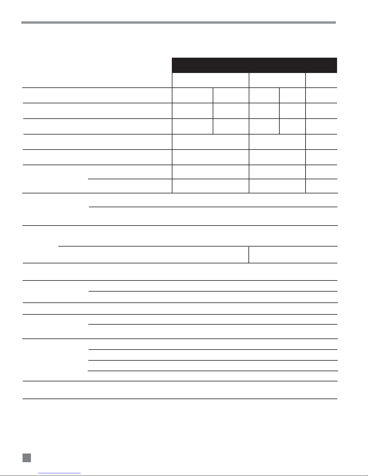
Tube Heater Specifications
Models
SPECIFICATIONS
Available Tube Lengths (ft.)
Net Weight (lbs.)
Shipping Weight (lbs.)
Maximum Input per Hour (BTUH)
Minimum Input per Hour (BTUH)
(Two Stage Gas Control)
Fuel Consumption
per Hour (Max.)
Inlet Gas Supply
Pressure Acceptable
at the Inlet of the
Heater for Purpose of
Input Adjustment
MAIN IN SINGLE STAGE CONTROL
Burner
Manifold
Pressure
SECOND STAGE IN TWO
STAGE CONTROL
FIRST STAGE IN TWO
STAGE CONTROL
Ventilation Air Required
to Support Combustion
L.P. GAS (lbs.)
NAT. GAS (cu. ft.)
MAX.
MIN.
AT100 AT125 AT150
30 40 40 50 50
120 150 150 180 180
140 170 170 200 200
100,000 125,000 150,000
65,000 75,000 90,000
4.63 5.79 7.09
100 125 150
13.5 in. W.C., L.P. and Natural Gas
11.0 in. W.C., L.P. Gas
7.0 in. W.C., Natural Gas
10.0 in. W.C., L.P. Gas
4.0 in. W.C., Natural Gas
4.5 in. W.C., L.P. Gas
2.0 in. W.C., Natural Gas
140 CFM
4.0 in. W.C., L.P. Gas
1.8 in. W.C., Natural Gas
Motor Characteristics
Electrical Supply (Volts/Hz/Phase)
Amp Draw
(Starting Amps
Include Igniter)
Minimum Safe
Distances of Heater
STARTING 1.16
CONTINUOUS
OPERATION
TOP
SIDES 6 ft.
From Nearest
Combustible Materials
(See Fig. 1 on page 5)
DISCHARGE END 6 ft.
BELOW RADIANT TUBES 6 ft.
Temperature Sensor Location
(See Fig. 2 on page 5)
4
Ball Bearing
1/30 H.P., 3020 RPM, CW Rotation
115/60/1
1.02
1 ft.
12-18 in. Above Litter and Approx. 15 Ft. Down from Burner Box
6 FT
6 FT
6 FT
6 FT 6 FT
6 FT
6 IN
FIG. 1
LITTER
INSIDE WATER LINE
SENSOR
TO AN IN
SAFE CLEARANCES FROM COMBUSTIBLES
FIG. 2
TEMPERATURE SENSOR LOCATION
HEATER
WATER LINES
INSIDE WATER LINE
FEED LINE
1 FT
SENSOR LOCATED DIRECTLY
ABOVE INSIDE WATER LINE AND
12-18 IN. ABOVE THE LITTER
FEED LINE
12-18 IN.
INSTALL SENSOR APPROX. 15 FT DOWN FROM BURNER BOX
INSIDE WATER LINE
LITTER
12"-18"
SENSOR
5
Safety Precautions
Asphyxiation Hazard
■ Do not use this radiant heater for heating human living
quarters.
WARNING
L.B. White Company to determine combustion air
ventilation requirements of the heater.
■ Do not use in unventilated areas.
■ The flow of combustion and ventilation air must not be
obstructed.
■ Proper ventilation must be provided to support the
combustion air requirements of the heater being used.
■ Refer to the specification section of the Owner’s
Manual, heater’s dataplate, or contact the
■ Lack of proper ventilation air will lead to carbon
monoxide poisoning in humans leading to serious
injury or death. Symptoms of carbon monoxide
poisoning can include headaches, dizziness and
difficulty in breathing.
■ Symptoms of improper ventilation affecting livestock
can be disease, lower feed conversion, or death.
FUEL GAS ODOR
Propane gas and natural gas has man-made odorant added specifically for detection of fuel gas leaks.
If a gas leak occurs, you should be able to smell the fuel gas.
THAT’S YOUR SIGNAL TO GO INTO IMMEDIATE ACTION!
■ Do not take any action that could ignite the fuel gas. Do
not operate any electrical switches. Do not pull any
power supply or extension cords. Do not light matches
or any other source of flame. Do not use your
telephone.
■ Get everyone out of the building and away from the area
immediately.
■ Close all propane (LP) gas tank or cylinder fuel supply
valves, or the main fuel supply valve at the meter if you
use natural gas.
■ Propane gas is heavier than air and may settle in low
areas. When you have reason to suspect a propane
leak, keep out of all low areas.
■ Natural gas is lighter than air and can collect around
rafters or ceilings.
■ Use your neighbor’s phone and call your fuel gas
supplier and your fire department. Do not re-enter the
building or area.
■ Stay out of the building and away from the area until
declared safe by the firefighters and your fuel gas
supplier.
■ FINALLY, let the fuel gas service person and the
firefighters check for escaped gas. Have them air out
the building and area before you return. Properly
trained service people must repair the leak, check for
further leakages, and then relight the heater for you.
ODOR FADING -- NO ODOR DETECTED
■ Some people cannot smell well. Some people cannot
smell the odor of the man-made chemical added to
propane or natural gas. You must determine if you
can smell the odorant in this fuel gas.
■ Learn to recognize the odor of propane gas or natural
gas. Local propane gas dealers will be more than
happy to give you a “scratch and sniff” pamphlet. Use it
to become familiar with the fuel gas odor.
■ Smoking can decrease your ability to smell. Being
around an odor for a period of time can affect your
sensitivity to that particular odor. Odors present in
animal confinement buildings can mask fuel gas odor.
■ The odorant in propane gas and natural gas is
colorless and the intensity of its odor can fade under
some circumstances.
■ If there is an underground leak, the movement of gas
through the soil can filter the odorant.
■ Propane gas odor may differ in intensity at different
levels. Since propane gas is heavier than air, there may
be more odor at lower levels.
■ Always be sensitive to the slightest gas odor. If you
continue to detect any gas odor, no matter how small,
treat it as a serious leak. Immediately go into action as
discussed previously.
ATTENTION -- CRITICAL POINTS TO REMEMBER!
■ Propane gas and natural gas has a distinctive odor.
Learn to recognize this odors. (Reference “Fuel Gas
Odor” and “Odor Fading” sections above.
■
If you have not been properly trained in repair and service
of propane gas and natural gas fueled heaters, then do
not attempt to light the heater, perform service or repairs,
or make any adjustments to the heater on a propane gas
or fuel system.
6
■ Even if you are not properly trained in the service and
repair of radiant heaters, ALWAYS be consciously aware
of the odors of propane gas and natural gas.
■ A periodic “sniff test” around the heater or at the
heater’s joints; i.e. hose, connections, etc., is a good
safety practice under any conditions. If you smell even
a small amount of gas, CONTACT YOUR FUEL GAS
SUPPLIER IMMEDIATELY. DO NOT WAIT!

1. Do not attempt to install, repair, or service this heater
or the gas supply line unless you have continuing
expert training and knowledge of gas heaters.
Qualifications for service and installation of this
equipment are as follows:
a.
To be a qualified gas heater service person, you
must have sufficient training and experience to
handle all aspects of gas-fired heater installation,
service and repair. This includes the task of
installation, troubleshooting, replacement of
defective parts and testing of the heater. You
must be able to place the heater into a continuing
safe and normal operating condition. You must
completely familiarize yourself with each model
heater by reading and complying with the safety
instructions, labels, Owner’s Manual, etc., that is
provided with each heater.
b.
To be a qualified gas installation person, you must
have sufficient training and experience to handle
all aspects of installing, repairing and altering gas
lines, including selecting and installing the proper
equipment, and selecting proper pipe and tank
size to be used. This must be done in accordance
with all local, state and national codes as well as
the manufacturer’s requirements.
5. For safety, this heater is equipped with an differential
air pressure switch. Never operate this heater if this
safety device has been bypassed. Do not operate this
heater unless this feature is fully functioning.
6. The heater is designed to operate only with its access
door closed and latched. Do not operate the heater
with its burner box access door open.
7. Do not block air intakes or discharge outlets of the
heater. Doing so may cause improper combustion or
damage to heater components leading to property
damage or animal loss.
8. The hose assembly shall be visually inspected on an
annual basis. If it is evident there is excessive
abrasion or wear, or if the hose is cut, it must be
replaced prior to the heater being put into operation.
The hose assembly shall be protected from animals,
and contact with hot surfaces during use. The hose
assembly shall be that specified by the manufacturer.
See parts list.
9. Check for gas leaks and proper function upon heater
installation and before building repopulation.
10. This heater should be inspected for proper operation
by a qualified service person at least annually.
2. All installations and applications of L.B. White heaters
must meet all relevant local, state and national
codes. Included are L.P. gas, electrical, and safety
codes. Your local fuel gas supplier, a local licensed
electrician, the local fire department or similar
government agencies, or your insurance agent can
help you determine code requirements.
-- ANSI/NFPA 58, latest edition, Standard for
Storage and Handling of Liquefied Petroleum
Gas and/or
-- ANSI Z223.1/NFPA 54, National Fuel Gas
Code
-- ANSI/NFPA 70, National Electrical Code.
3. Do not move, handle, or service heater while in
operation or connected to a power or fuel supply.
4. This heater may be installed in areas subject to
washdown. This heater may only be washed on the
external components. See Cleaning Instructions. Do
not wash the interior of the burner box or the tubes.
Use only compressed air, soft brush or dry cloth to
clean the interior of the heater and it’s components.
After external washdown, do not operate this heater
until it is completely dry. In any event, do not operate
the heater for at least one hour after external
washdown.
11. Always turn off the gas supply to the heater when not
in use.
12. This heater is equipped with a three-prong
(grounding) plug for your protection against shock
hazard and must be plugged directly into a properly
grounded three-prong receptacle. Failure to use a
properly grounded receptacle can result in electrical
shock, personal injury, or death.
13. Direct ignition heaters will make up to three trials for
ignition. If ignition is not achieved, the control system
will lock out the gas control valve. If gas is smelled
after system lock out has occurred, immediately close
all fuel supply valves. Do not relight until you are sure
that all gas that may have accumulated has cleared
away. In any event, do not relight for at least 5
minutes.
14. Use only approved gas hose or approved flexible
connectors which are rated for use with propane or
natural gas.
7
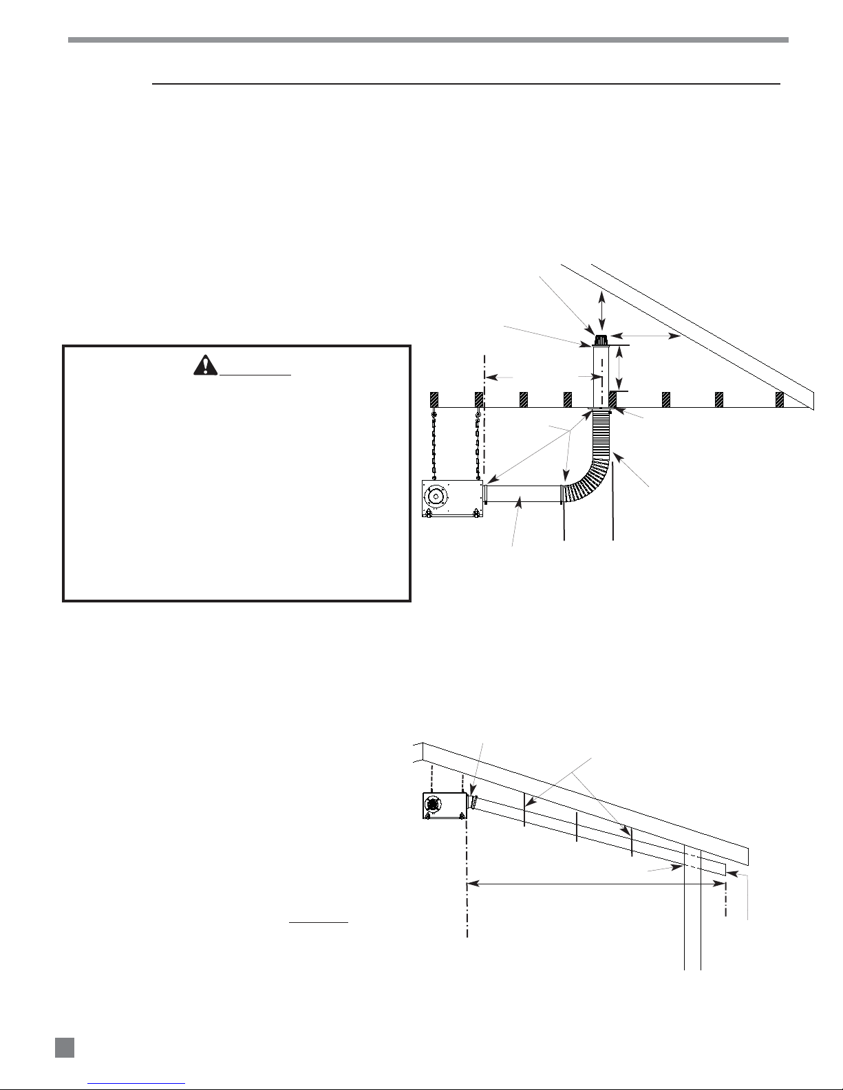
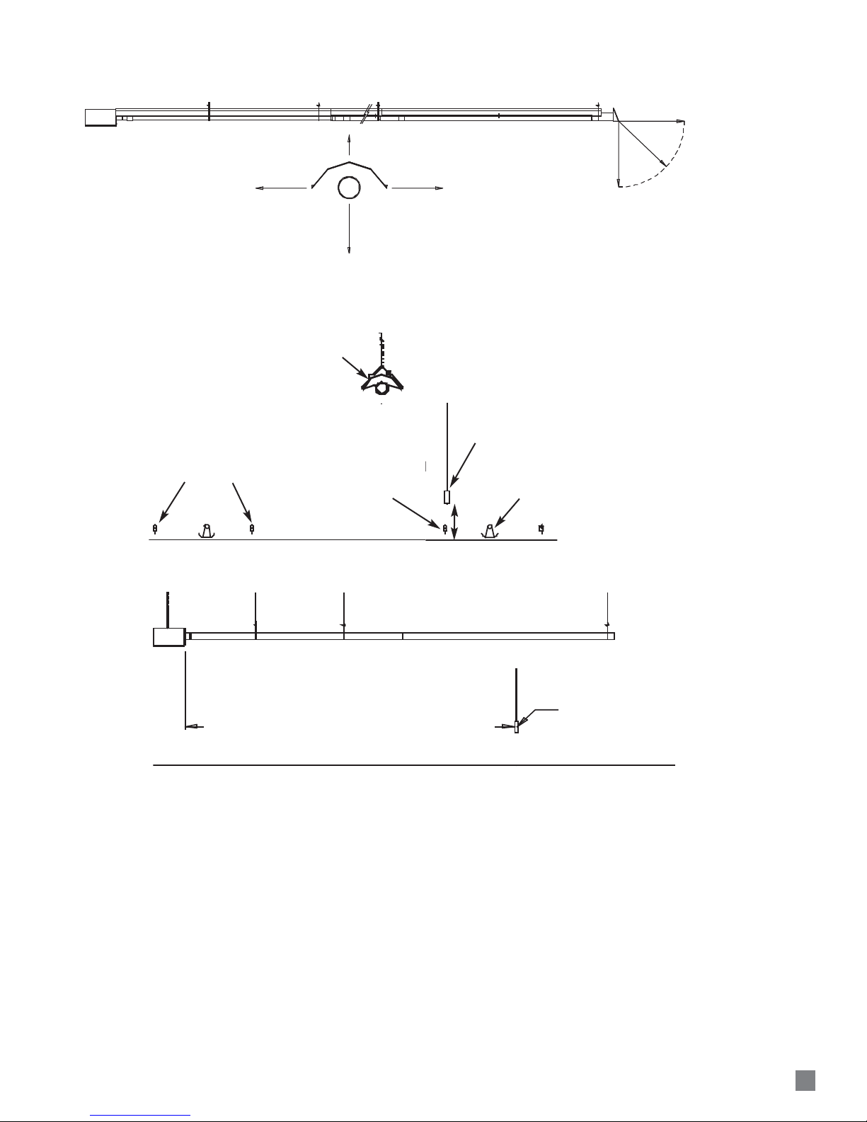
Inlet Air Requirement
The air inlet system must be kept as straight
as possible. No more than 1 - 90º bend is
allowed.
Drawing Inlet Air From Attic
Drawing Inlet Air Through Side Walls
Installation Instructions
GENERAL
1. Read all safety precautions and follow L.B. White
recommendations when installing this heater. If
during the installation of the heater, you suspect that
a part is damaged or defective, call a qualified
service agency for repair or replacement.
2 A qualified service agency must check the heater
upon installation and periodically. This shall consist
of the following:
c. locations where wind and/or the
elements can create a negative
pressure.
■ Use L.B.White air inlet kit 24950:
-- Start up and shut down of the heaters to test for
proper operation.
-- Leak check all gas pipe joints and gas hose
connections.
-- Gas pressure checks.
-- Ensuring the heater is properly positioned away
from combustible materials.
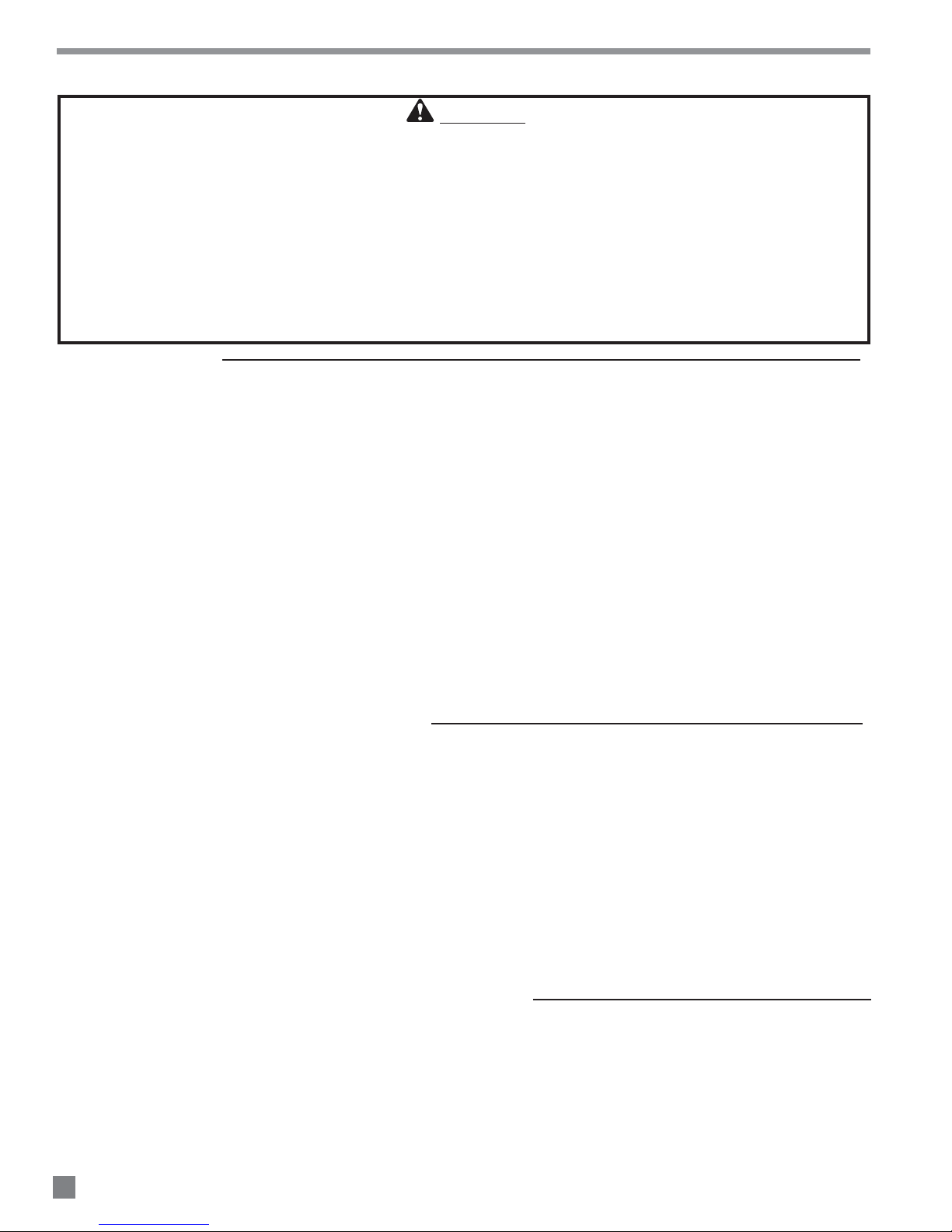
WARNING
Combustion Hazard
■ Provide a properly located and sized fresh air inlet for
the heater.
-- Refer to Inlet Air Requirements instructions.
■ Failure to provide a fresh air inlet can lead to:
-- Sooting causing building damage
-- High carbon monoxide levels, causing serious
injury or death to livestock and humans
-- Overheating of the first 10 ft. tube, causing fires
leading to building damage and injury to livestock
and humans.
-- Higher temperature differences over the length of
the tubes, causing problems in temperature
control and bird performance
FIG. 3
ENSURE INLET CAP IS
UNBLOCKED BY INSULATION
SMOOTH INLET TUBE, MAX. 2
FT. LENGTH, 4 IN. DIA.
(FIT OVER CEILING FLANGE)
INLET CENTER
30-40 IN. FROM
BURNER BOX
CLAMPS
24 IN. RIGID TUBE
MINMIZE
HORIZONTAL
TRAVEL OF
FLEX DUCT
CUT TUBE 6 IN. SHORTER IF CEILING FLANGE IS CLOSER THAN 30 IN.
FROM BURNER BOX.
ADD ADDITIONAL LENGTH OF 4 IN. RIGID TUBE (NOT INCLUDED) IF
CEILING FLANGE IS 40 IN. OR MORE FROM BURNER BOX.
12 IN. MIN.FROM
INSIDE OF ROOF
12 IN. MIN. ABOVE
INSULATION
CUT 4 1/4 IN. HOLE THROUGH CEILING
ADJACENT TO JOIST. SPREAD INSULATION
AWAY AND FASTEN CEILING FLANGE TO
JOIST.
FLEX TUBE CUT TO LENGTH
-- DO NOT EXCEED 4 FT. MAX. LENGTH
-- DO NOT KINK
ROOF
3.I
This heater requires clean, fresh air from a
normal, atmospheric pressure environment for
proper operation and combustion. Contact
L.B.White Company if you have any questions
regarding the installation of this heater.
Inlet air may be drawn from the attic or through
side walls under a protective eve. See Figs. 3
and 4.
-- All inlet air seams and joints must be sealed
-- Do not use any filters on the air inlet system
-- T
-- Contact L.B.White Co. if you have any
questions regarding the installation of
the heater
Inlet air for combustion must not be drawn
from:
■ Inside the confinement room.
■ An attic or location where negative pressure
8
s:
(vacuum) affects the air draw of the heater’s
fan. Examples include, but are not limited to:
a. houses with attic soffit vent area smaller
than ridge cap vent area
b. heater air inlet located within 20 ft. of
building ventilation fans
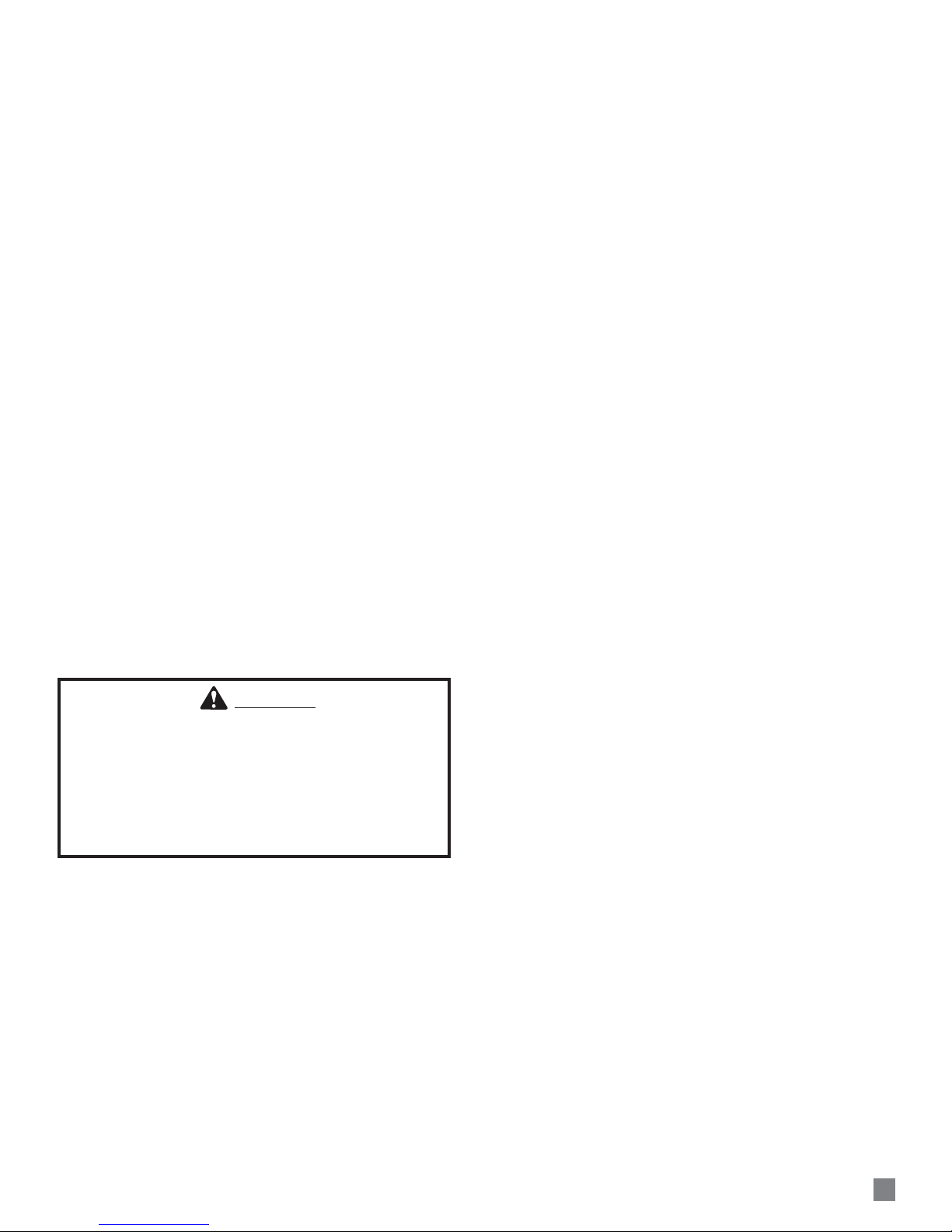
FIG. 4
USE MINIMUM LENGTH OF 4 IN DIAMETER FLEX DUCT WHEN
CONNECTING 4 IN.PVC TO BURNER BOX.
AN ADAPTER CONNECTION FOR THE BURNER BOX TO THE 6 IN.PVC
MUST BE OBTAINED THROUGH LOCAL SOURCE.
INSTALL SUPPORTS EVERY 5 FT. TO
PREVENT INLET SAGGING
ROOF
AIR INLET
SECURE INLET TO WALL
FOR INLET RUNS UP TO 20 FT., USE SMOOTH 4 IN. ID PVC
FOR RUNS OVER 20 FT., USE 6 IN.ID. PVC
4. The heater is approved for indoor use
only
WALL
AIR INLET
USE INLET CAP,
24861 FOR 4 IN PVC
CAN ALSO USE
1/4 X 1/4 HARDWARE
CLOTH FOR EITHER
4 IN. OR 6 IN. PVC
5. Heater installation must take into consideration
proper hanging height to allow for clearance of
catching machines, litter spreaders, and any other
equipment used.
6. Ensure the heater installation does not interfere with
water, gas, or electrical lines.
7. Position the gas hose to prevent any contact with the
tubes, heat relectors, and burner box.
-- If a leak is detected, check the components
involved for cleanliness in the thread areas and
proper application of pipe compound before
further tightening.
-- Tighten the gas connection as necessary to stop
the leak.
-- If necessary, replace the parts or components
involved if the leak cannot be stopped.
-- Ensure all gas leaks have been identified and
repaired before proceeding.
8. Ensure that all accessories that ship with the heater
have been removed from shipping containers and
installed. This pertains to gas hose, regulators,
supports, hangers, etc.
9. This heater requires a regulated gas supply to its gas
inlet :
-- The regulator must be the proper design for the
application.
-- The regulator must control the inlet pressure to
the heater within the range specified on the
dataplate.
-- Regulators mounted outside must be protected
from adverse weather conditions.
-- Regulators with pressure relief valves should be
installed outside the building.
-- Regulator installed inside should be vented
outside.
-- Local state and national codes apply to regulator
installation. Refer to NFPA 54, National Fuel Gas
Code, and NFPA 58, Standard for Storage and
Handling of Liquified Petroleum Gas.
10. Always use pipe joint compound that is resistant to
liquefied petroleum gas and natural gas.
11. Check all connections for gas leaks using approved
gas leak detectors. Gas leak testing is performed as
follows:
WARNING
Fire and Explosion Hazard
■ Do not use open flame (matches, torches, candles,
etc.) in checking for gas leaks.
■ Use only approved leak detectors.
■ Failure to follow this warning can lead to fires or
explosions.
■ Fires or explosions can lead to property damage,
injury or death.
-- Check all pipe connections, hose connections,
fittings and adapters upstream of the gas
control with approved gas leak detectors.
-- In the event a gas leak is detected, check the
components involved for cleanliness and proper
application of pipe compound before further
tightening.
-- Tighten the gas connections as necessary to
stop the leak.
-- After all connections are checked and any leaks
are stopped, turn on the main burner.
-- Stand clear while the main burner ignites to
prevent injury caused from hidden leaks that
could cause flashback.
-- With the main burner in operation, check all
connections, hose connections, fittings and
joints as well as the gas control valve inlet and
outlet connections with approved gas leak
detectors.
12. Install a sediment trap at the gas valve inlet to
prevent foreign materials (pipe compound, pipe
chips and scale) from entering the gas valve. Debris
blown into the gas valve may cause that valve to
malfunction resulting in a serious gas leak that
could result in a possible fire or explosion causing
loss of products, building or even life. A properly
installed sediment trap will keep foreign materials
from entering the gas valve and protect the safe
functioning of that important safety component.
13. Any heater connected to a piping system must have
an accessible, approved manual shut off valve
installed within six feet (6 ft.) of the heater it serves.
14. Install the proper gas supply line to assure proper
functioning of the heaters. Consult your fuel gas
supplier, or the L.B. White Co., Inc. for proper line
sizing and installation.
15. Light according to instructions on heater or within
Owner’s Manual.
16. The heater is designed for L.P. vapor withdrawal or
natural gas only. Do not use this heater in a
propane liquid withdrawal system. Do not permit
propane in liquid form to enter the heater at any
time.
17. The corrosive atmosphere present in animal
confinement buildings can cause component failure
or heater malfunction. The heater should be
periodically inspected and cleaned in accordance
with the Maintenance and Cleaning Instructions in
this manual. Make sure that livestock is protected
by a back up alarm system that limits high and low
temperatures and also activates appropriate alarms.
18. Take time to understand how to operate and
maintain the heater using the owner’s manual.
Make sure you know how to shut off the gas supply
to the building and to the heater. Contact your gas
supplier if you have any questions.
19. Any defects found in performing any of the service
procedures must be eliminated and defective parts
replaced immediately. Retest the heater before
placing it back into service.
20. Do not exceed input rating stamped on the
dataplate of the heater. Do not exceed the burner
manifold pressure stated on the dataplate. Do not
use an orifice size different than specified for the
specific input rating of this heater, fuel type
configuration and altitude.
9
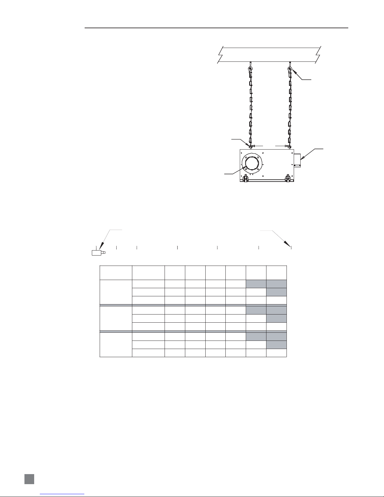
INITIAL SETUP
1. Plan the installation. Determine location for the
heater to optimize its heat pattern, keeping in mind
cooler regions in the house (end walls, and curtains)
and clearances to combustibles.
2. Hang the burner box. See Fig. 5. Maintain clearances
to combustibles as shown in Fig. 1.
3. From the burner box chain, measure the distances
shown in Fig. 6. Aligning to the center of the burner
box discharge, hang chains at these points, using
open eye hooks.
FIG. 6
FIG. 5
OPEN EYE BOLT
BURNER
DISCHARGE
OPEN EYE HOOKS
IN LINE WITH
EYE BOLTS ON
BURNER BOX
JOIST
1 FT
TIGHTEN HOOKS
SECURELY
AIR INLET
BURNER BOX
A
B
TRUSS
CENTERS
4 FOOT
5 FOOT
10 FOOT
* A SUPPORT MUST BE CREATED BETWEEN THE TRUSSES
C
HEATER
LENGTH
30 FOOT
40 FOOT
50 FOOT
30 FOOT
40 FOOT
50 FOOT
30 FOOT
40 FOOT
50 FOOT
D
HANGING CHAIN DISTANCES
A - B
B - C C - D D - E
(FT)
(FT)
4
4
4
5
5
5
5
*
*
5
5
*
HANGING CHAINS
E
(FT) (FT) (FT) (FT)
4
4
4
5
5
5
5
5
5
12
12
12
10
10
10
10
10
10
8
8
8
10
10
10
10
10
10
F
E - F F - G
12
12
5
10
5
10
8
5
*
5
G
*
10
 Loading...