

Page 1
Installation Instructions for
980MROCKCW
Mini-Rock Candy Cylinder Wall
WALL
GENERAL PRODUCT INFORMATION:
This product is suitable for damp locations.
This product can mount either to a 4” square electrical box with a
round plaster ring or an octagon electrical box.
This product can be dimmed with a standard incandescent dimmer.
This instruction shows a typical instruction.
CAUTION - RISK OF FIRE
This product requires installation by a qualified
electrician. Before installing be sure to read all
instructions and TURNTHE POWER TO THE
ELECTRICAL BOX OFF.
HW623_2G
1.0
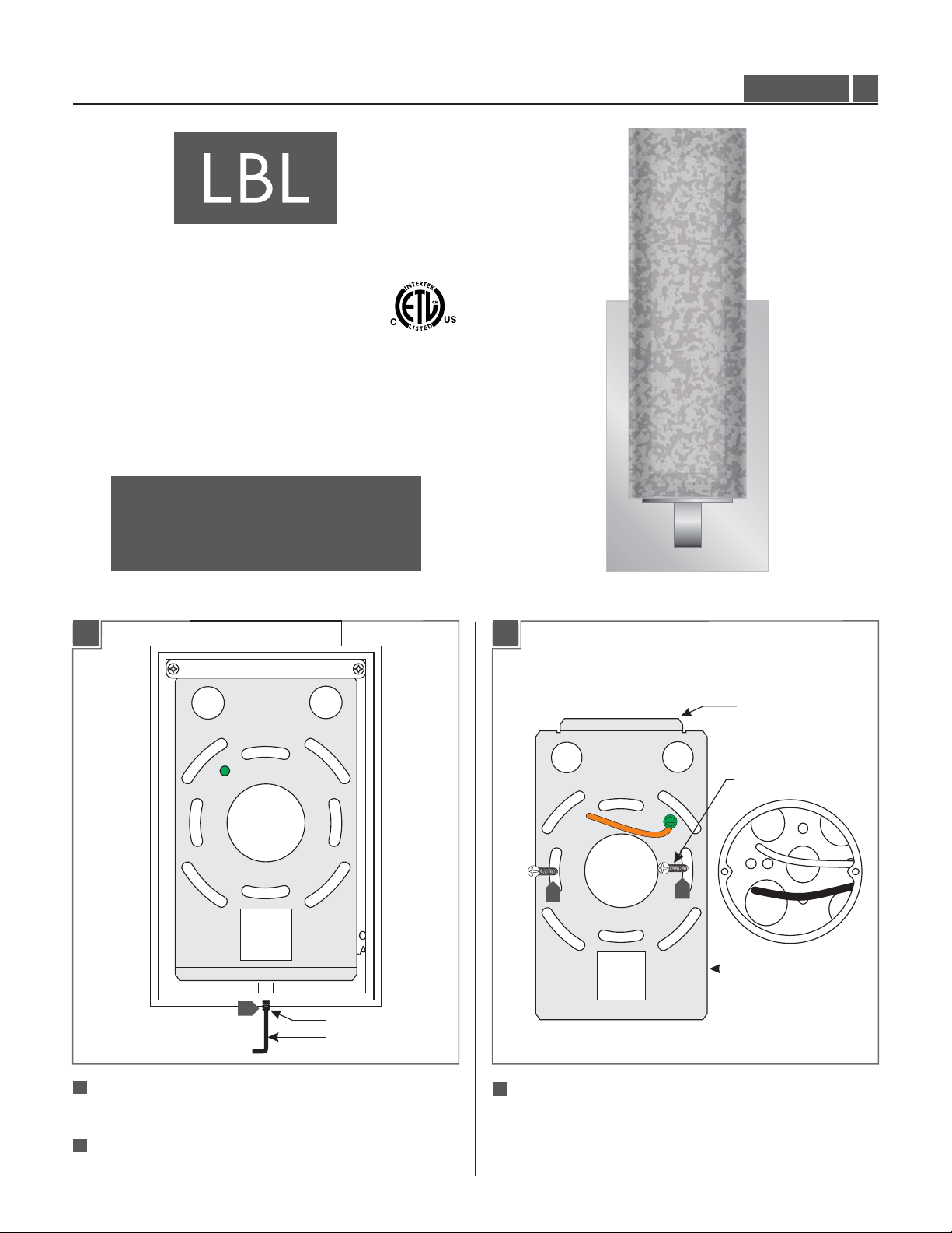
Install the Fixture
1A
1
MOUNTING
PLATE
SET SCREW
ALLEN WRENCH
1B
NOTCHED END
#8-32 SCREW
3
3
MOUNTING
PLATE
1
With the Allen wrench provided, back out (do not fully
remove) the set screws at the base of the fixture.
2
Remove the mounting plate from the back of the
fixture.
3
Attach the mounting plate to the electrical box using
the two #8-32 screws provided. Make sure the notched
end of the mounting plate is at the top.
1
Page 2
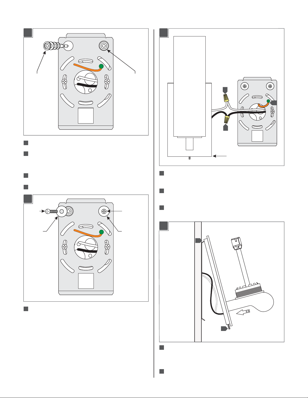
1C
ANCHOR
4
Verify that the mounting plate is level before continuing.
5
Line up an anchor tip with the center of the mounting
plate hole and push the anchor into the wall up to the
threads.
61E6
Screw the anchors in the rest of the way.
Repeat steps 4-6 for the other anchor.
67
1D
SCREW
SCREW
ANCHOR
10
11
SCONCE
Connect the mounting plate ground wire to a suitable
69
ground in accordance to local electrical codes.
Connect the white fixture wire to the neutral power line
610
wire with a wire nut.
611
Connect the black fixture wire to the hot power line
wire with a wire nut.
9
WASHER
Slide a #8 screw through a washer and screw it into an
68
WASHER
anchor. Repeat for the other anchor to secure the
mounting plate to the wall.
1F
12
13
612
Hook the top of the sconce to the top of the mounting
plate and swing the bottom of the sconce toward the
plate until it is flush with the wall.
613
Tighten the set screw at the bottom of the sconce to
secure it to the mounting plate.
2
Page 3

Install the Lamp and Shades
2A
CAUTION: To reduce the risk of a burn or electric
shock during relamping, disconnect the power to
the fixture.
2C
LAMP
SOCKET
OUTER
GLASS
SHADE
SOCKET
ASSEMBLY
BASE
Use Volt, type T4, G9 base
MAX 60120 Watt
bi-pin halogen lamp in each socket.
NOTE: Use only your fingers and a soft cloth to
replace the lamp.
1
Push the lamp base completely into the socket.
2B
INNER
GLASS
SHADE
3
Carefully screw the outer glass shade onto the socket
assembly base until it is firmly in place.
NOTE:To re-lamp, reverse the section 2 instructions.
SOCKET
ASSEMBLY
BASE
2
Gently push the inner glass shade into the center of the
socket assembly base until it is firmly in place.
3
Page 4

SAVE THESE INSTRUCTIONS!
7400 Linder Ave, Skokie, IL 60077
800.323.3226 - 847.626.6300
www.lbllighting.com
© 2012 LBL Lighting.All rights reserved. The "LBL Lighting" graphic is a
registered trademark of LBL Lighting. LBL Lighting reserves the right to
change specifications for product improvements without notification.
A Generation Brands Company
4
 Loading...