

Page 1
Installation Instructions for
980JUNPRSPCF
Juniper (Compact Fluorescent)
Suspension
GP I :ENERAL RODUCT NFORMATION
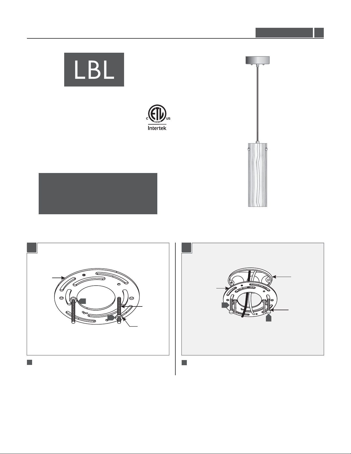
This product can mount to either a 4" square electrical box with
round plaster ring or an octagon electrical box.
This product is suitable for indoor dry locations only.
CAUTION - RISK OF FIRE
This product must be installed in accordance with
the applicable installation code by a person familiar
with the construction and operation of the product
and the hazards involved.
Use minimum 90°c supply conductors.
PF229OPSC32T
1.0
Install the Fixture
CROSSBAR
1
1
NUT
11
Screw one nut onto each threaded rod and tighten it to secure
the threaded rod in place.
THREADED
ROD
1B1A
CROSSBAR
2
2
2
Mount the crossbar to the electrical box with two #8-32
screws.
ELECTRICAL
BOX
#8-32 SCREW
1
Page 2
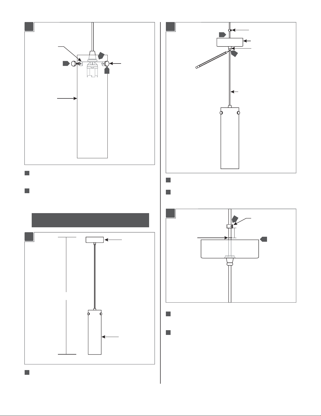
1C
SOCKET
BRACKET
3
4
4
GLASS SHADE
3
Place the glass shade onto the socket bracket and align the
glass shade holes with socket bracket holes.
THUMB SCREW
1E
6
7
6
Feed the cord into the canopy and plastic strain relief.
PLASTIC STRAIN RELIEF
CANOPY
BUSHING
CORD
4
Tighten the three thumb screws through the glass shade holes
completely into the socket bracket holes to secure the glass
shade in place.
NOTE:Do not over tighten the thumb screws which may
cause the glass shade to break.
1D
(H)
CANOPY
GLASS SHADE
7
Adjust the fixture height and mark the cord below the canopy
bushing.
1F
9
7
MARKED LINE
8
Feed the cord inside the canopy so that the marked line is
PLASTIC STRAIN
RELIEF
1"
8
exposed behind the canopy.
Hold the plastic strain relief 1" above the marked line and
9
tighten the set screw.
5
Determine the desired fixture height (From the bottom of
glass shade to the top of canopy).
2
Page 3

1G
1J
CAP
M4 SET
SCREW
10
Slide the canopy up against the plastic strain relief and tighten
2 MM ALLEN
WRENCH
the M4 set screw snugly on the cap with 2 MMAllen wrench.
1H
4"
12
13
16
17
15
In accordance with local electrical codes, make sure that the
15
crossbar and fixture ground wire are grounded.
16
Connect the white ballast wire to the neutral power line wire
with a wire nut.
17
Connect the black ballast wire to the hot power line wire with
a wire nut.
1K
11
Leave 6" of the cord behind the canopy for power connections
and cut the excess cord.
12
From the end of the cord remove 4" of the cord insulation.
13
Strip 1/4" of the insulation from the wire ends.
1I
14
14
WIRE NUT
BALLAST
THREADED ROD
CAP NUTS
18
Place all wires and wire nut connections properly inside the
19
19
canopy housing.
19
Slide the canopy onto the threaded rods and secure it in place
by tightening the cap nuts completely to the threaded rods.
14
Connect one ballast wire to each fixture wire (except ground
wire) with a wire nut.
3
Page 4

Install the Lamp
2A
SOCKET
LAMP
SAVE THESE INSTRUCTIONS!
CAUTION:To reduce the risk of a burn or electric shock
during relamping, disconnect the power to the fixture.
Use WattTypeTripleTubeMAX 32
GX24q-3 Base Compact Fluorescent
Lamp.
1
Push the lamp pins completely into the socket holes.
7400 Linder Ave, Skokie, IL 60077
800.323.3226 - 847.626.6300
www.lbllighting.com
© 2014 LBL Lighting.All rights reserved. The "LBL Lighting" graphic is a
registered trademark of LBL Lighting. LBL Lighting reserves the right to
change specifications for product improvements without notification.
4
A Generation Brands Company
 Loading...