

Page 1
Installation Instructions for
980JUNPRSP
Juniper
Suspension
GP I :ENERAL RODUCT NFORMATION
This product can mount to either a 4" square electrical box with
round plaster ring or an octagon electrical box.
This product is suitable for indoor dry locations only.
This product can be dimmed with a standard incandescent dimmer.
CAUTION - RISK OF FIRE
This product must be installed in accordance with
the applicable installation code by a person familiar
with the construction and operation of the product
and the hazards involved.
Use minimum 90°c supply conductors.
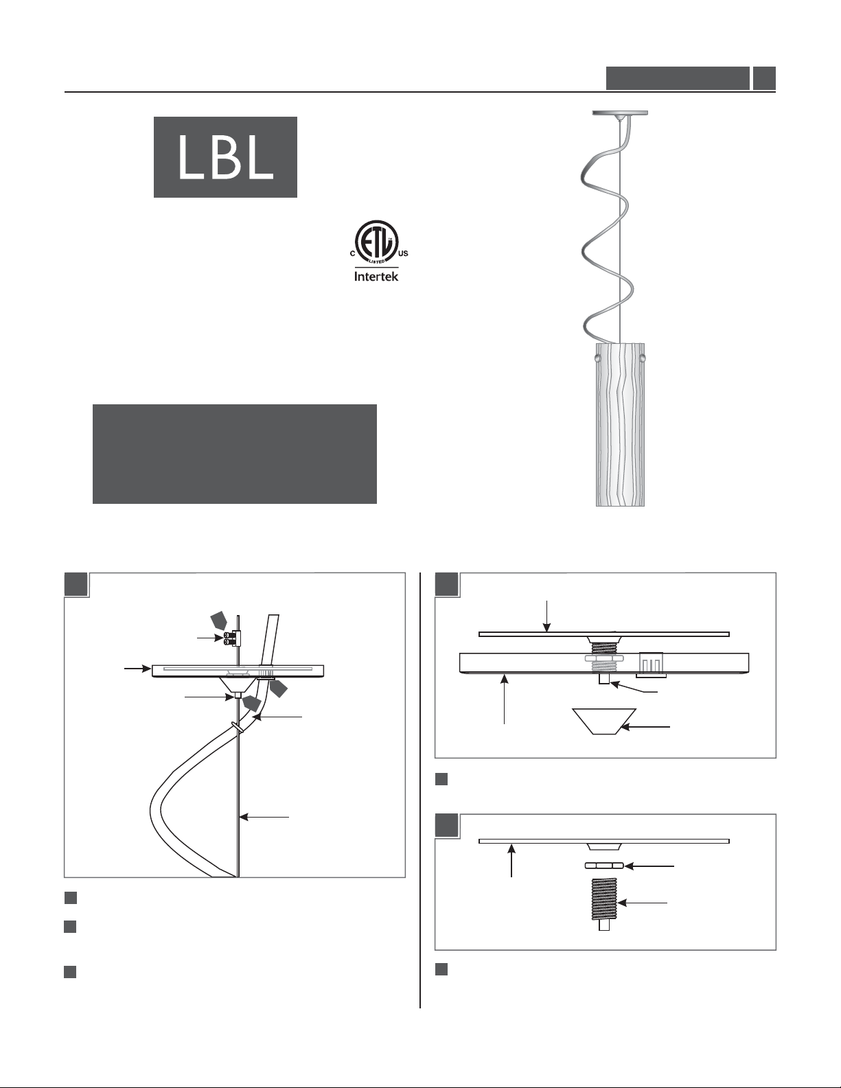
LF229OPSC2D100
1.0
Install the Fixture
1A
2
METAL STRAIN RELIEF
CANOPY
TA B
11
Pull the clear cord out of the canopy.
2
Remove the two screws on the metal strain relief and remove
it from the aircraft cable.
1
3
CLEAR CORD
AIRCRAFT CABLE
1B
4
Loosen the cap from the cable grip to remove the crossbar.
CANOPY
CROSSBAR
CABLE GRIP
CAP
1C
NUT
CROSSBAR
CABLE GRIP
3
Push the tab down on cable grip and pull out the aircraft cable.
5
Loosen to remove the nut and cable grip from the crossbar.
1
Page 2
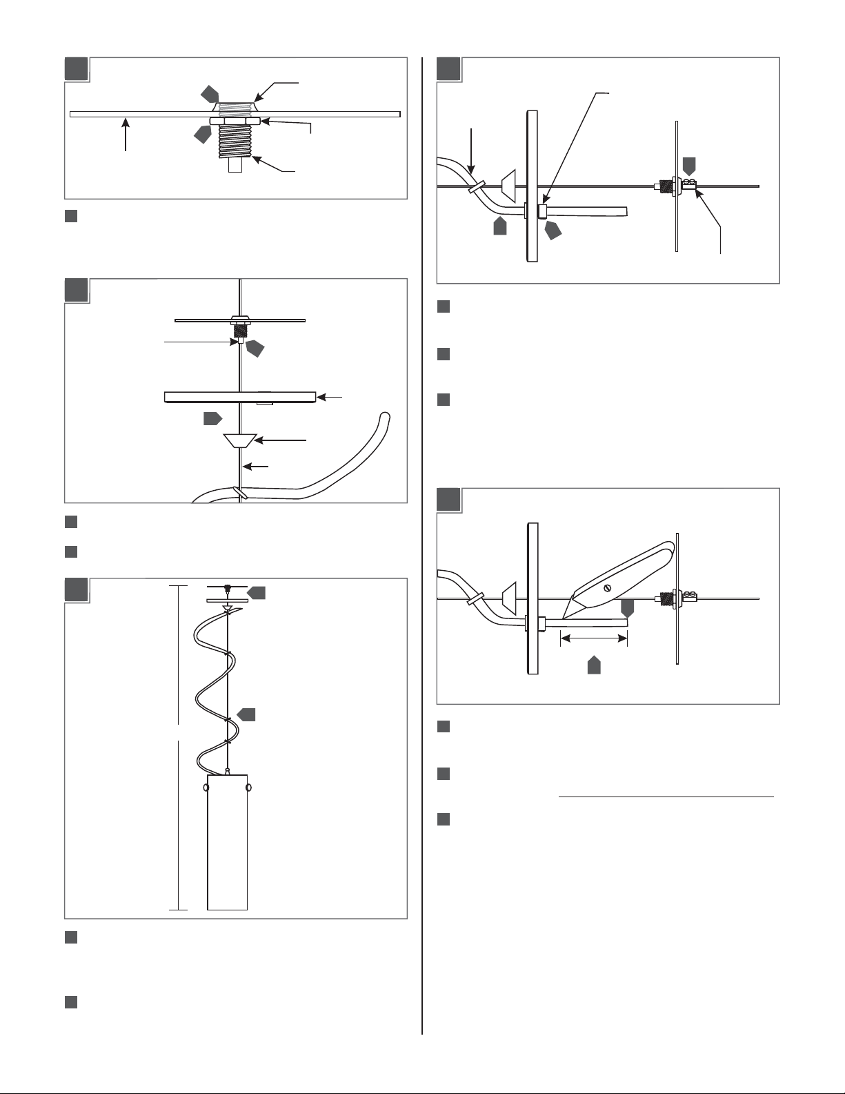
1D
6
CROSSBAR LIP
PLASTIC STRAIN
RELIEF
1G
6
CROSSBAR
6
Insert the cable grip to the crossbar so that the cable grip is
NUT
CABLE GRIP
flush to the top of crossbar lip.Tighten the nut completely
against the crossbar to secure the cable grip.
1E
CABLE GRIP
5
7
7
Slide the cap and canopy down the aircraft cable respectively.
8
CAP
AIRCRAFT
CABLE
CANOPY
CLEAR CORD
11
13
11
Slide the metal strain relief onto the aircraft cable against the
12
METAL STRAIN
RELIEF
crossbar and tighten the screws.
12
Insert the clear cord from the canopy side hole into the
canopy.
13
Slide the plastic strain relief onto the clear cord against the
canopy. Dress the clear cord around the aircraft cable and
tighten the screw on plastic strain relief.
1H
8
Push the tab on cable grip and insert the aircraft cable in.
1F
H
9
Adjust the fixture to desired height (From the bottom of glass
10
9
shade to the top of crossbar) by pushing the tab on cable grip
and sliding the aircraft cable up and down.
16
11
14
Leave 6" of the cord behind the canopy for power connections.
4"
15
Cut the excess clear cord.
15
From the end of the clear cord, strip the outer insulation 4"
using a sharp knife. .Make sure not to nick the inner wires
16
Strip the end of the wires.
10
When desired height is achieved release the tab of the cable
grip to lock the aircraft cable in place.
2
Page 3

1I
1K
18
AIRCRAFT CABLE
CAUTION:Cut the access aircraft cable behind the metal
strain relief and make sure that it does not come in contact
with power wires or ground.
17
Connect the fixture ground wire to the ground in accordance
17
18
with local electrical codes.
18
Connect the fixture wires properly to power line wires with
wire nuts.
Place all wires and wire nut connections properly inside the
19
electrical box.
CABLE GRIP
21
Slide the canopy up against the ceiling and secure it by
CAP
21
tightening the cap to cable grip.
CANOPY
1J
20
20
Mount the crossbar to the electrical box with the two #8-32
screws.
#8-32 SCREW
20
3
Page 4

Install the Lamp
2A
CAUTION:To reduce the risk of a burn or electric shock
during relamping, disconnect the power to the fixture.
Use Volt, WattType A19MAX 100120
Medium Base Lamp.
1
Screw the lamp completely into the socket.
SOCKET
CAP
SAVETHESE INSTRUCTIONS!
7400 Linder Ave, Skokie, IL 60077
800.323.3226 - 847.626.6300
www.lbllighting.com
© 2014 LBL Lighting.All rights reserved. The "LBL Lighting" graphic is a
registered trademark of LBL Lighting. LBL Lighting reserves the right to
change specifications for product improvements without notification.
4
A Generation Brands Company
 Loading...