

Page 1
Installation Instructions for
980BOX2IN
2” Electrical Box
ACCESSORIES
GP I :ENERAL RODUCT NFORMATION
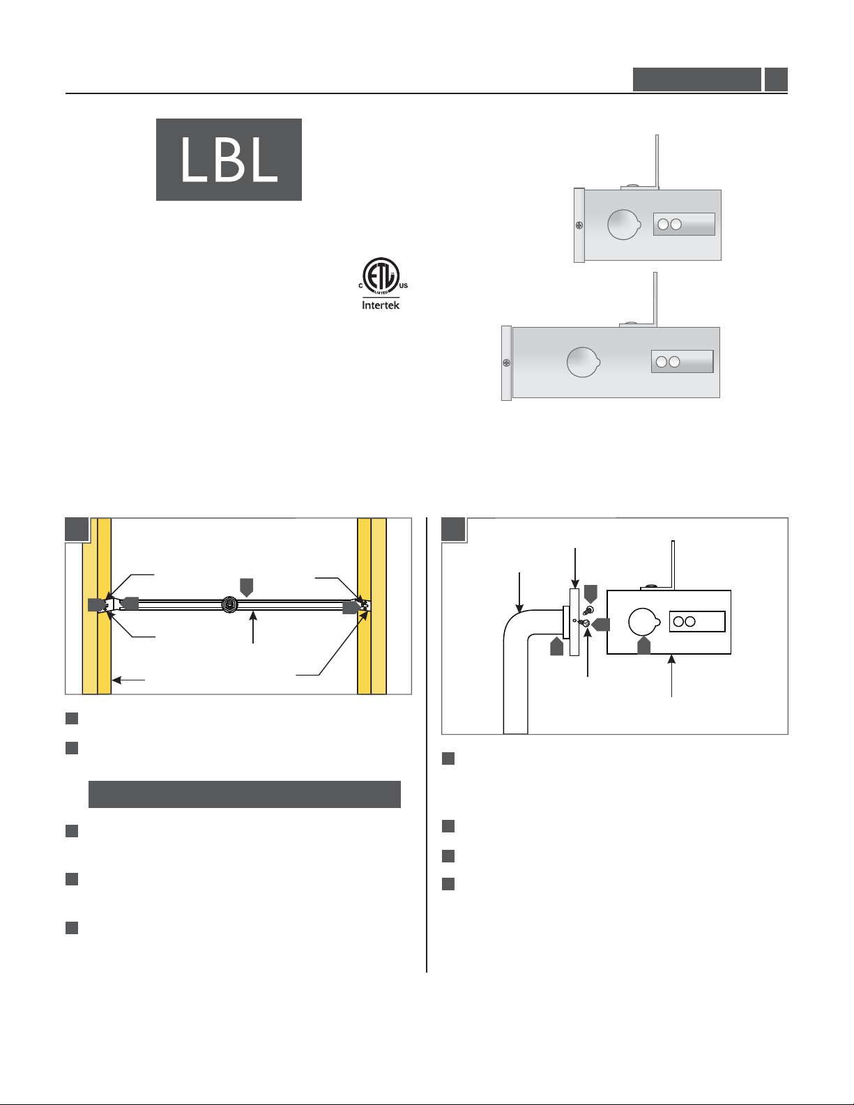
This product must only be used with LBL lighting systems.
Minimum volume of the electrical box must be 6 cubic inches (98
cubic centimeter).
ELEC-BOX-2”
1.0
For New Construction Installation
1A
#8 SCREW
4
3
#8 SCREW
STUD
1
Select the location for the 2" electrical box.
2
Place the adjustable bar between the studs.
NOTE:The adjustable bar is for studs that are 16" apart.
3
Line up the front edge of the side brackets with front
edge of the studs.
4
Hammer the tabs on side brackets into the studs to hold
the adjustable bar.
2
ADJUSTABLE BAR
SIDE BRACKET
TAB
5
1B
CONDUIT
6
If mounting the conduit onto back of the 2" electrical
box, remove the two #4 screws from the back cover to
detach the back cover from the box.
7
Remove the knock out and mount the conduit.
8
Replace the back cover and #4 screws if removed.
9
Conduit can also be mounted on the side knockouts.
BACK COVER
6
7
#4 SCREW
8
9
2" BOX
5
Secure the adjustable bar into the studs with four #8
screws.
1
Page 2
1C
1E
REAR HOLES
FOR 5/8"
DRYWALL
THICKNESS
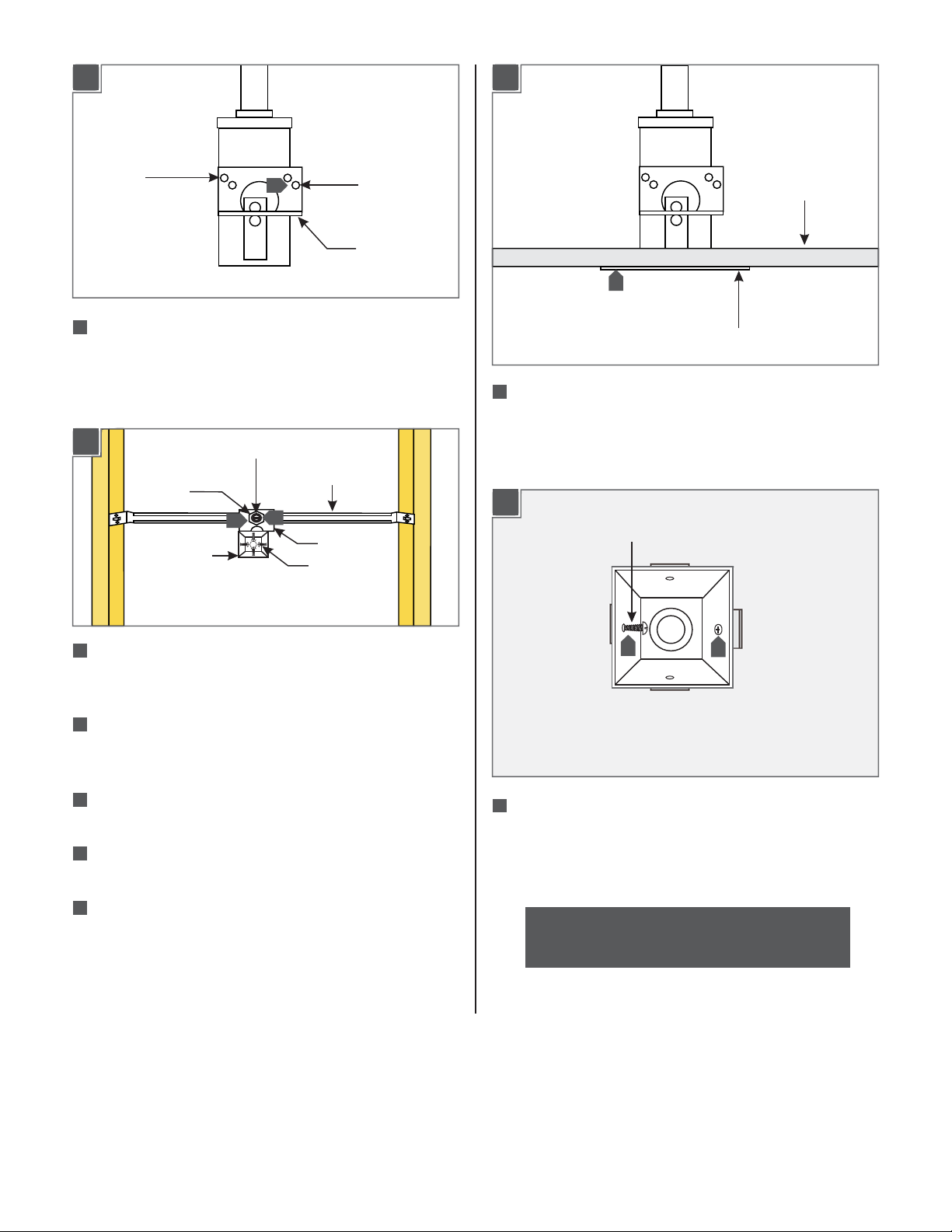
10
For 1/2" drywall thickness mount the "L" bracket on the
10
FRONT HOLES
FOR 1/2"
DRYWALL
THICKNESS
"L" BRACKET
2" electrical box by using the two front holes. For 5/8"
drywall thickness mount the "L" bracket to the 2"
electrical box by using the two rear holes.
1D
2" ELECTRICAL
BOX
FLAT HEAD SCREW
NUT
11
ADJUSTABLE BAR
12
"L" BRACKET
#6 SCREW
DRY WALL
16
DRESSING PLATE
16
After installing the drywall, place the dressing plate on
the 2" electrical box. The dressing plate should cover the
plaster or open spaces around the 2" electrical box.
1F
#6 SCREW
11
Remove the nut on the adjustable bar and place the "L"
bracket onto the nipple. Tighten the nut to secure the 2"
electrical box.
12
Loosen the flat head screw on the adjustable bar and
slide the 2" electrical box to the desired position. Tighten
the flat head screw to secure the 2" box in position.
13
Remove the four #6 screws on the front of the 2"
electrical box.
14
Mark a 1-13/16" square on the drywall where the 2"
electrical box is going to be located.
15
Cut out the marked square with a sharp knife and install
the drywall.
17
17
Replace and tighten two #6 screws on opposing sides
17
of the 2” electrical box so that the spring tabs on the
side of the 2" electrical box push out against the drywall
and secure the box in place.
NOTE: Refer to the canopy instructions for final
installation.
2
Page 3

For Retrofit Installation
2A
1-13/16”
1
1
Mark a 1-13/16" square on the drywall where the 2"
1-13/16”
ACTUAL SIZE
electrical box is going to be located. The drawing above
can be used as a template.
2
Cut out the marked square with a sharp knife.
2B
FLEXIBLE
CONDUIT
BACK COVER
4
3
#6 SCREW
2C
8
7
Remove the four #6 screws on the front of the 2"
electrical box.
8
Place the 2" electrical box into the square cut out.
7
2D
#6 SCREW
#6 SCREW
6
5
#4 SCREW
2" BOX
3
Loosen the two #4 screws on the back cover. Remove
the back cover.
4
Remove the two #6 screws on the "L" bracket. Remove
the "L" bracket.
NOTE: The "L" bracket and adjustable bar are not
used for retrofit installations.
5
Remove the knockout from the back cover and mount
the flexible conduit.
6
Replace the back cover and #4 screws on the 2"
electrical box.
9 9
9
Replace and tighten two #6 screws on opposing sides
of the 2” electrical box so that the spring tabs on the
side of the 2" electrical box push out against the drywall
and secure the box in place.
NOTE: Refer to the canopy instructions for final
installation.
3
Page 4

SAVE THESE INSTRUCTIONS!
7400 Linder Ave, Skokie, IL 60077
800.323.3226 - 847.626.6300
www.lbllighting.com
© 2014 LBL Lighting.All rights reserved. The "LBL Lighting" graphic is a
registered trademark of LBL Lighting. LBL Lighting reserves the right to
change specifications for product improvements without notification.
4
A Generation Brands Company
 Loading...