

Page 1
Installation Instructions for
980CONSTGSCF
Constellation Grande (Compact Fluorescent)
Suspension
GP I :ENERAL RODUCT NFORMATION
This product is suitable for damp locations.
CAUTION - RISK OF FIRE
This product requires installation by a qualified
electrician. Before installing be sure to read all
instructions and TURNTHE POWER TO THE
ELECTRICAL BOX OFF.
Assemble the Fixture
LP747_CF
1.0
1A
21
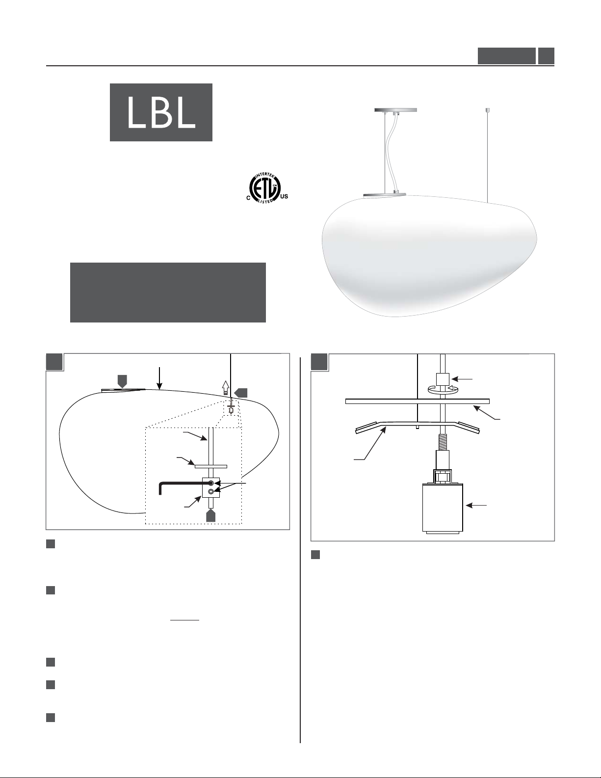
Loosen the two set screws on the stopper at the bottom
of the cable post aircraft cable using the provided Allen
wrench.
22
Determine the desired height of the fixture, move the
stopper to the determined location, and tighten the two
set screws on the stopper. Take note of theNOTE:
height measurement, it will be needed for the canopy
aircraft cable.
SHADE
4
5
AIRCRAFT
CABLE
RUBBER
GROMMET
STOPPER
3
SET SCREW
1B
CAP
COVER
BRACKET
SOCKET
6
Disassemble the socket assembly by unscrewing the cap
and separating the socket, bracket, and the cover.
23
Cut off the excess aircraft cable.
24
Ensure that the rubber grommet is in place and install
the separate aircraft cable into the shade.
25
Feed the open end through the small hole in the shade
and pull it all the way through until the stopper is
reached.
1
Page 2
1C
1E
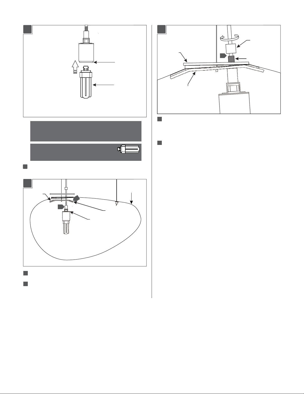
CAP
CAUTION:To reduce the risk of a burn or electric shock
during relamping, disconnect the power to the fixture.
Use MAX 32 Watt GX24Q-3
Triple Tube Compact Fluorescent lamp.
1
7
Hold the socket with one hand and push the lamp base
firmly all the way into the socket.
1D
CUSHION
PAD
8
9
BRACKET
SOCKET
LAMP
SHADE
COVER
BRACKET
210
Place the socket nipple through the bracket hole and
11
NIPPLE
pull the assembly up until it rests inside the top of the
shade.
211
Place the cover over the top of the shade opening lip,
ensure that the bracket is centered and is gripping the
shade properly, and secure it all by screwing on and
tightening the cap.
SOCKET
ASSEMBLY
8
Place the socket assembly inside the shade.
29
Ensure that the cushion pads are in place and insert the
bracket into the shade by slightly rotating it into place.
2
Page 3
Shorten the Power Cord
2A
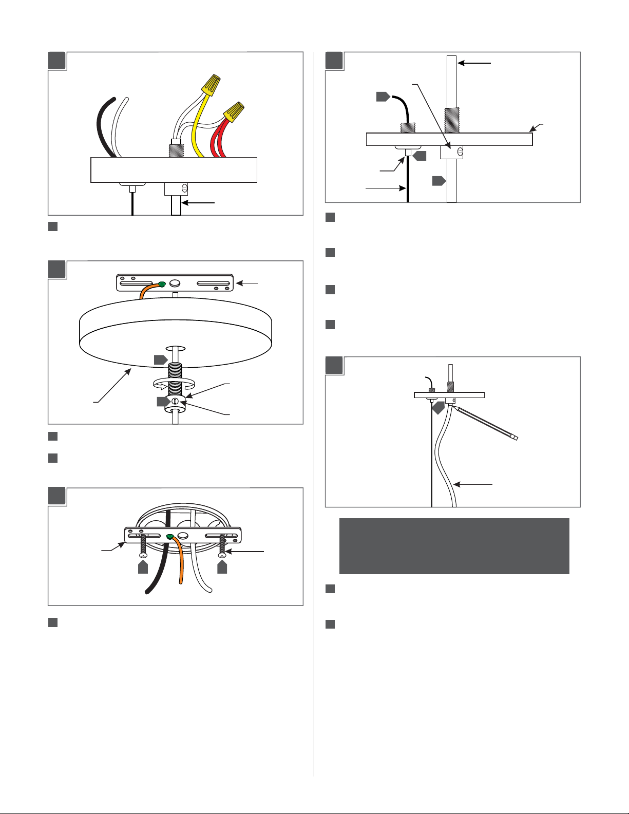
POWER CORD
1
Take note of the wire connections and remove the wire nuts
to disconnect the power cord wires from the driver wires.
2B
CROSSBAR
2D
STRAIN RELIEF
7
CABLE
CLUTCH
AIRCRAFT
CABLE
5
Feed the aircraft cable through the cable clutch in the
5
8
POWER CORD
canopy.
6
2
Pull the aircraft cable up through the canopy to raise
the fixture to the determined length.
Cut off the excess aircraft cable leaving enough for fine
7
2
leveling later.
8
2
Pull the power cord through the canopy to the desired
length.
3
STRAIN RELIEF
CANOPY
2
Loosen the set screw on the strain relief.(Do Not Remove)
3
Remove the crossbar from the canopy by completely
2
SET SCREW
unscrewing the strain relief.
2C
CROSSBAR
4 4
4
Mount the crossbar assembly to the electrical box with
the two provided #8-32 screws.
#8-32
SCREW
2E
10
CORD
NOTE: The power cord does not support the fixture.
For a casual “lazy cord” look, cut the power cord
several inches longer that the drop height of the
fixture.
2
9
Once the desired look is determined, tighten the set
screw on the strain relief.
10
2
Mark the cord underneath the strain relief.
3
Page 4

2F
3B
7
4"
711
Leave 6" of the cord behind the canopy for power
connections. Cut the excess cord.
7
12
From the end of the cord, strip the insulation 4" using a
sharp knife. .Make sure not to nick the inner wires
7
13
Strip the end of the wires.
Mount the Fixture
CAUTION: Make sure to support the fixture while
installing, an assistant will be needed to complete
the remaining steps.
3A
2
3
4
7
6
5
BALLAST
25
10
Connect the red ballast wires to one of the insulated
pendant wires.
26
Connect the yellow ballast wire to the other insulated
pendant wire.
7
Ground the fixture to a suitable ground in accordance
2
with local electrical codes.
8
2
Connect the white ballast wire to the neutral power line
wire.
9
2
Connect the black ballast wire to the hot power line
wire.
9
8
4
TAB
1
21
10
Feed the fixture wires through the crossbar center hole
and then pull them out of the electrical box.
22
Install the secondary strain relief by first feeding the
power cord through it.
23
Snap the strain relief tab into place.
24
Pull the cord to take up the slack and fit the rest of the
cord in the strain relief’s openings.
4
Page 5

Install the Cable Post
3C
SET SCREW
STRAIN RELIEF
CORD
10
Place all wires, wire nut connections, and the secondary
strain relief properly inside the electrical box.
11
Loosen the set screw on the primary strain relief.
12
Align the canopy center hole with the crossbar center
hole.
13
Slide the canopy up against the ceiling and secure it in
place by tightening the primary strain relief into the
crossbar. Do not turn the cord.
CAUTION: Make sure to support the fixture while
installing, an assistant will be needed to complete
the remaining steps.
4A
10”
CABLE CLUTCH
CABLE POST LOCATION
14
Push the cord into the canopy and line up the marked
point on the cord with bottom of the primary strain
relief.
Tighten the plastic set screw to secure the cord.
15
CAUTION: CONTINUE TO SUPPORT THE SHADE!
Do not let the fixture hang with out the completion
of the cable standoff installation (next section).
71
Mark the cable post location point 10” away from the center
cable clutch on the canopy. .
4B
2
ANCHOR
CEILING
Tap the anchor at the marked point up to the threaded portion
72
with a hammer.
5
Page 6

Adjust the Suspension Cable
4C
3
Screw the anchor in the rest of the way with a Phillips
73
screwdriver.
4D
ANCHOR
WASHER
#8 SCREW
4
THREADED NIPPLE
5A
1
CABLE
CLUTCH
CAUTION: Make sure to support the fixture while
making adjustments, an assistant will be needed to
complete this step.
74
Insert the #8 screw into the threaded nipple and washer.
Tighten the #8 screw completely into the anchor to secure the
washer and threaded nipple in place.
4E
5
CABLE POST
5
Screw the cable post completely to the threaded nipple.
THREADED NIPPLE
1
If necessary, adjust the aircraft cable until the fixture is
level; feed the cable into the cable clutch to raise the
fixture and push in on the cable clutch nipple to release
the cable and lower the fixture.
6
Page 7

7
Page 8

SAVE THESE INSTRUCTIONS!
7400 Linder Ave, Skokie, IL 60077
800.323.3226 - 847.626.6300
www.lbllighting.com
© 2013 LBL Lighting.All rights reserved. The "LBL Lighting" graphic is a
registered trademark of LBL Lighting. LBL Lighting reserves the right to
change specifications for product improvements without notification.
A Generation Brands Company
8
 Loading...