

Page 1
Installation Instructions for
950CLFTN
Clifton Wall
GP I :ENERAL RODUCT NFORMATION
This product is suitable for damp locations.
Fixtures using incandescent lamps may be dimmed with a standard
incandescent dimmer.
CAUTION - RISK OF FIRE
This product must be installed in accordance with
the applicable installation code by a person familiar
with the construction and operation of the product
and the hazards involved.
Use minimum 90°c supply conductors.
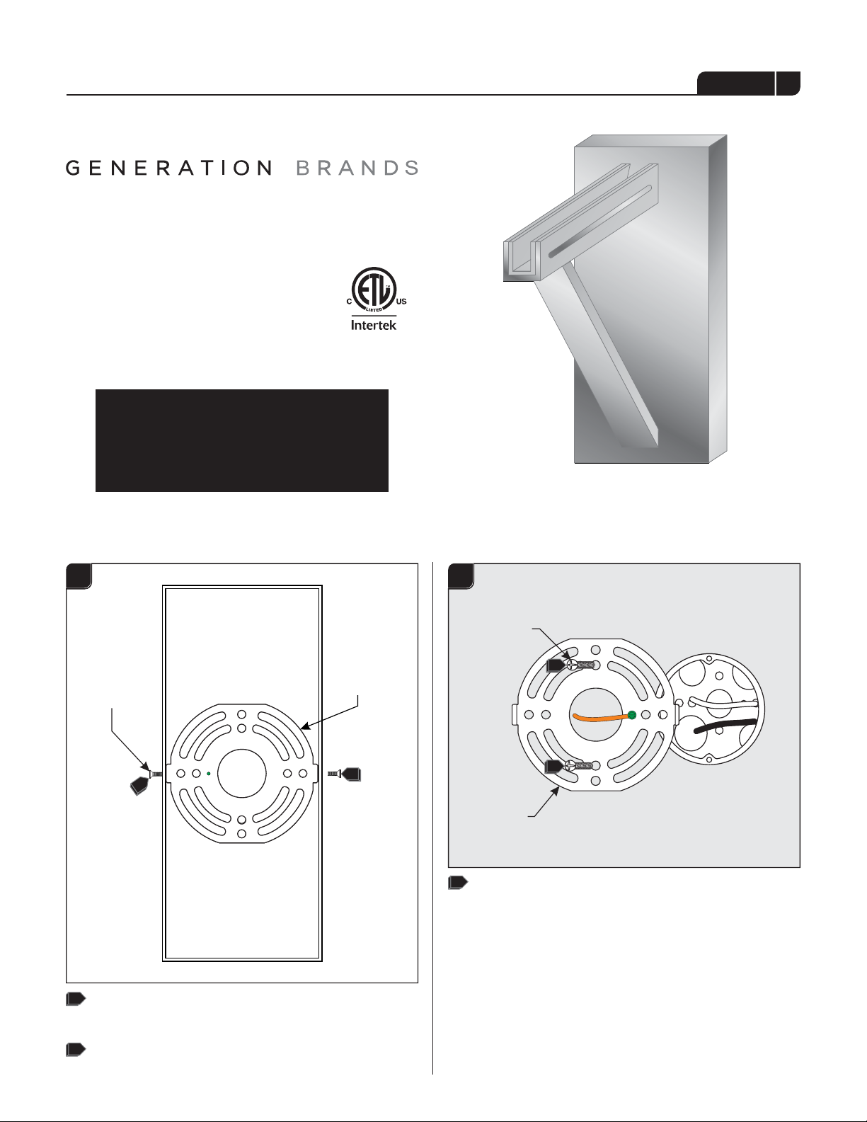
1.1
Install the Mounting Plate
1A1A
FIXTURE SCREW
1
MOUNTING
PLATE
1
1A1B
#8-32 SCREW
3
3
MOUNTING
PLATE
3
Attach the mounting plate to the electrical box using
the two #8-32 screws provided.
1
Remove the fixture screws located on both sides of the
fixture base.
2
Remove the mounting plate from the fixture base.
1
Page 2
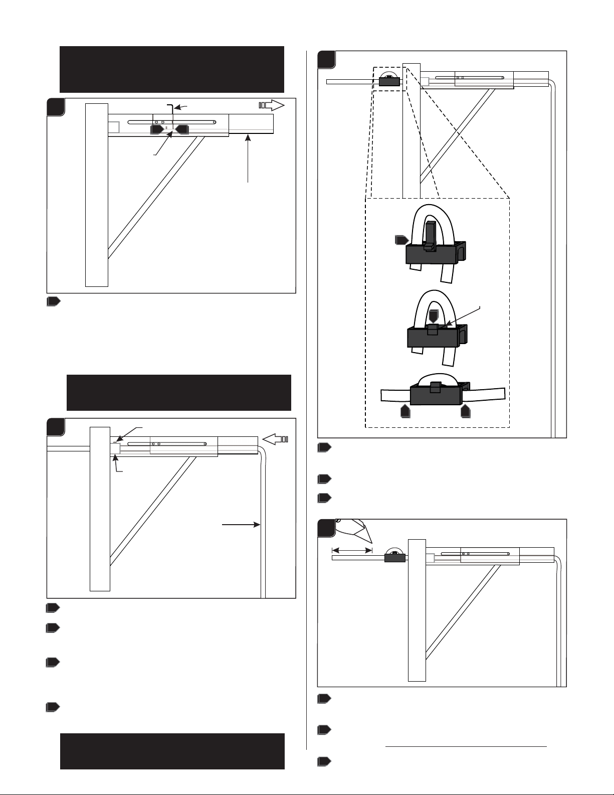
Adjust the Canopy
Note: Depending on the size of the shade and the
desired distance of the shade from the wall,
Adjustments of the canopy length can be made
using this section.
1A3B
1A2A
SET SCREW
If needed, adjust the canopy arm’s length by loosening
1
ALLEN WRENCH
11
CANOPY ARM
the two set screws on the top of the canopy arm, pull
the arm out to the desired position, and secure it in
place by re-tightening the set screws.
Install the Fixture
Note: It is important to plan out the desired height
of the pendant along with the desired distance from
the wall before shortening the cable.
1A3A
SET SCREW
5
TAB
6
7 7
STRAIN RELIEF
CORD
1
Loosen (Do Not Remove) the set screw on the strain relief.
2
Feed the cord through the primary strain relief and the
canopy.
3
Adjust the fixture height (from bottom of the fixture shade
to the canopy arm) by feeding the fixture cord through the
canopy and strain relief.
4
When the desired height is achieved, tighten the set screw
on the strain relief.
Note: If the fixture has a cord with a cloth cover,
taping down the frayed end of the cloth may assist
in feeding it through the strain relief.
5
Install the secondary strain relief by first feeding the
power cord through it.
6
Snap the strain relief tab into place.
7
Pull the cord to take up the slack and fit the rest of the
cord in the strain relief’s openings.
1A
3C
4"
Leave 6" of the cord behind the canopy for power
8
connections. Cut the excess cord.
From the end of the cord, strip the insulation 4" using a
9
sharp knife. .Make sure not to nick the inner wires
Strip the end of the wires.
10
2
Page 3

Wire the Fixture
BALLAST
3
1
5
6
Caution: The wiring diagram will vary depending on
the type of lamp and wattage of the fixture. Choose
the correct wiring method accordingly and make
sure to only use the transformer provided with your
pendant.
1A4B
Four Pin Compact Fluorescent
Version
1A4A
Incandescent and 24 CompactGU
FluorescentVersion
2
1
3
1
Connect the mounting plate ground wire and the fixture
ground wire to a suitable ground in accordance with
local electrical codes.
4
1
2
13 OR 18
WATT
2
BALLAST
26 OR 32
WATT
6
5
2
Connect the neutral power line to the insulated pendant
wire with the white tracer (white) using a wire nut.
Connect the hot power line to the other insulated
3
pendant wire (black) with a wire nut.
1
Connect the yellow ballast wire to the insulated pendant
wire with the white tracer (white wire) using a wire nut.
2
For 13 or 18 Watt lamps: Connect one of the red
ballast wires to the other insulated pendant wire (black)
with a wire nut. Cap off the other red ballast wire with a
wire nut.
3
For 26 or 32 Watt lamps: Connect both of the red
ballast wires to the other insulated pendant wire (black)
with a wire nut.
4
Connect the fixture and the crossbar ground wire to a
suitable ground in accordance with local electrical
codes.
135
Connect the white ballast wire to the neutral power line
wire with a wire nut.
136
Connect the black ballast wire to the hot power line wire
with a wire nut.
3
Page 4

Install the Canopy
1A4C
1
1
Connect the mounting plate ground wire and the fixture
LED Version
3
2
DRIVER
ground wire to a suitable ground in accordance with
local electrical codes.
Connect the white (blue) driver wire to the insulated
2
pendant wire with the white tracer (white wire) using a
wire nut.
3
Connect the black (red) driver wire to the other
insulated pendant wire (black) with a wire nut.
1A5A
FIXTURE SCREW
1
5
4
1
Properly place the secondary strain relief, transformer (if
applicable), wires, and wire nut connections into the
electrical box.
2
Mount the fixture by sliding it back onto the mounting
plate and reinstalling the two fixture screws (reversal of
figure 1A).
1
SAVETHESE INSTRUCTIONS!
7400 Linder Ave, Skokie, IL 60077
800.323.3226 - 847.626.6300
www.generation-brands.com
© 2014 Generation Brands.All rights reserved.The "Genereation Brands"
graphic is a registered trademark of Generation Brands. Generation Brands
reserves the right to change specifications for product improvements without
notification.
4
A Generation Brands Company
 Loading...