

Page 1
Installation Instructions for
980CALIX7S
Calix 7-Light Suspension (LED)
SU768_
Suspension
GP I :ENERAL RODUCT NFORMATION
This product is suitable for damp locations.
This product may be dimmed with a low-voltage electronic dimmer.
CAUTION - RISK OF FIRE
This product must be installed in accordance with
the applicable installation code by a person familiar
with the construction and operation of the product
and the hazards involved.
Use minimum 90°c supply conductors.
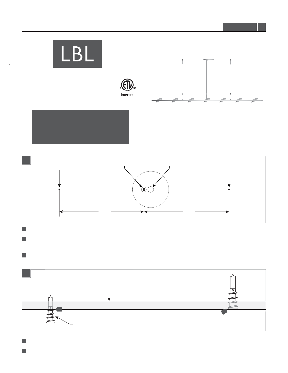
Install the Fixture
1A
AIRCRAFT CABLE POST LOCATION AIRCRAFT CABLE POST LOCATION
THUMB SCREWPOWER CORD POST
1.0
10.625” 10.625”
1
Determine the desired location fixture and center the canopy to the electrical box.
2
Ensure that the power cord port will be aligned with the canopy’s thumb screw and the locations of the two aircraft cable
posts as illustrated above.
3
While ensuring that the fixture’s location is aligned accordingly, make two aircraft cable post location marks 10.625” away
from the center of the power cord post.
1B
CEILING
4
ANCHOR
Tap the anchor at the marked point up to the threaded portion with a hammer.
74
5
Screw the anchor in the rest of the way with a Phillips screwdriver.
75
1
Page 2
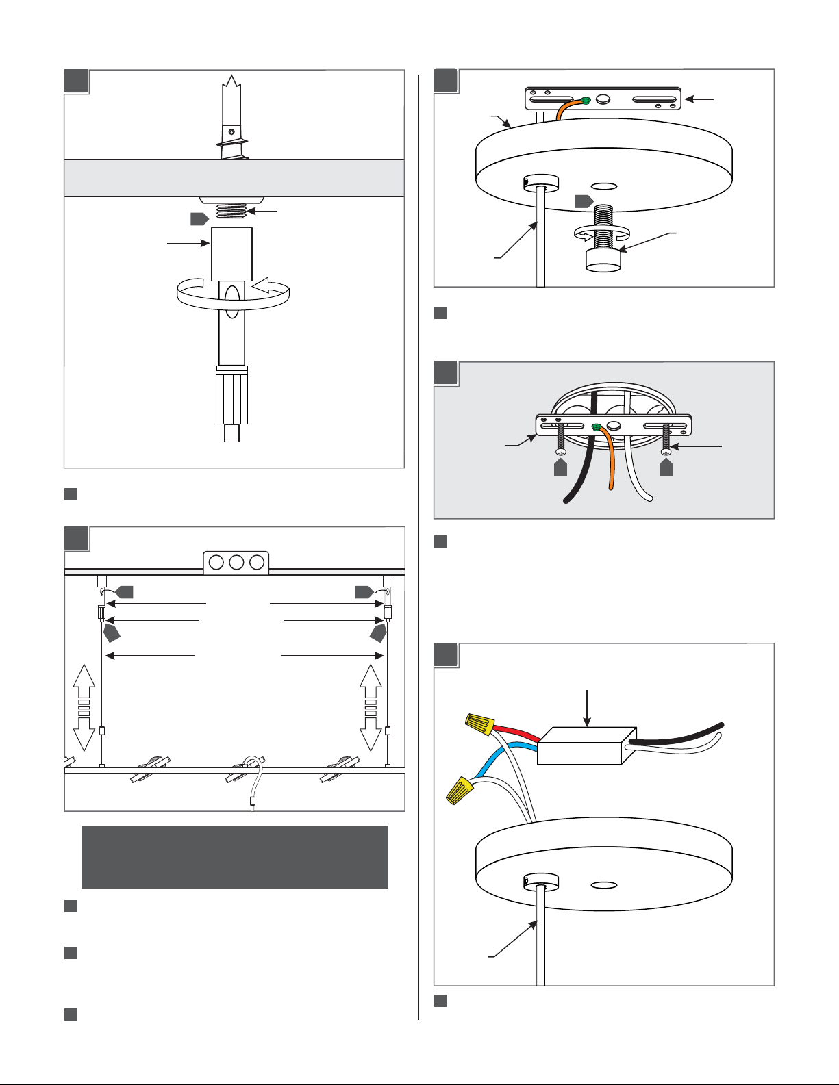
Prepare the Canopy
1C
CABLE POST
2A
CROSSBAR
CANOPY
3
6
THREADED NIPPLE
POWER
CORD
21
Remove the crossbar from the canopy by completely
1
THUMB SCREW
unscrewing the thumb screw.
2B
CROSSBAR
2 2
#8-32
SCREW
6
Screw the cable post completely to the threaded nipple.
1D
9
8
CAUTION: Make sure to support the fixture while
making adjustments, an assistant will be needed to
complete this step.
CABLE POST
CABLE CLUTCH
AIRCRAFT CABLE
2
Mount the crossbar assembly to the electrical box with
the two provided #8-32 screws.
9
8
Shorten the Power Cord (optional)
3A
DRIVER
7
Feed the aircraft cables through the cable post to the desired
length.
To level the fixture, push the tab on the cable clutch and feed
8
more or less of the support cable into the cable clutch. Make
fine adjustments to each cable until the fixture is level.
9
If necessary, trim the excess cable from the cable post.
POWER
CORD
1
Take note of the wire connections and remove the wire nuts
to disconnect the power cord wires from the driver wires.
2
Page 3

Install the Canopy
3B
SET SCREW
POWER
CORD
2
Loosen the 2 set screws on the strain(Do Not Remove)
4
3
STRAIN
RELIEF
relief.
3
Pull the power cords through the strain relief to the
desired length and re-tighten the 2 set screws.
4
Leave at least 6” of cord in the back of the canopy for
wire connections and trim off the excess cable.
5
From the end of the cord, strip the insulation 4" using a
sharp knife. .Make sure not to nick the inner wires
4A
1
3
3
DRIVER
2
6
Strip the end of the wires.
7
Reconnect the power cord wires to their original
connections to the driver (reversal of 2A).
POWER
CORD
21
10
Ground the fixture to a suitable ground in accordance
with local electrical codes.
22
Connect the white driver wire to the neutral power line
wire.
3
Connect the black driver wire to the hot power line
2
wire.
3
Page 4

4B
5
THUMB SCREW
24
Properly place the driver, all wires, and wire connections into
the electrical box.
25
Mount the canopy to the crossbar by completely screwing in
the thumb screw.
NOTE: If installing the canopy onto a electrical box
with a plaster ring, loosen the screws to the crossbar
to insert the driver into the electrical box, then retighten the screws the screws to the crossbar.
Adjust the Heads
5A
22
Rotate the heads to the desired direction.
SAVETHESE INSTRUCTIONS!
7400 Linder Ave, Skokie, IL 60077
800.323.3226 - 847.626.6300
www.lbllighting.com
© 2014 LBL Lighting.All rights reserved. The "LBL Lighting" graphic is a
registered trademark of LBL Lighting. LBL Lighting reserves the right to
change specifications for product improvements without notification.
4
A Generation Brands Company
 Loading...