

Page 1
Installation Instructions for
980BAYBR3CH
Baybridge 3 Light
Chandeliers
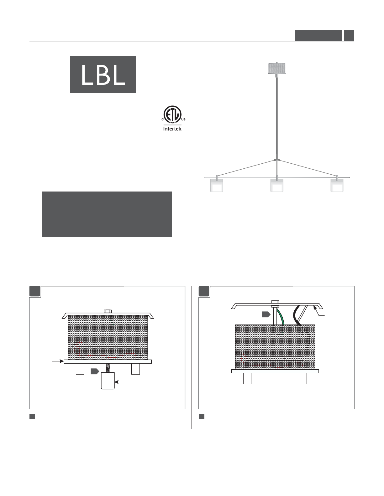
GP I :ENERAL RODUCT NFORMATION
This product can mount to either a 4" square electrical box with
round plaster ring or an octagon electrical box.
This product is suitable for indoor dry locations only.
This product can be dimmed with an electronic dimmer.
CAUTION - RISK OF FIRE
This product must be installed in accordance with
the applicable installation code by a person familiar
with the construction and operation of the product
and the hazards involved.
Use minimum 90°c supply conductors.
HS1861_1A
1.1
Install the Fixture
1A
CANOPY
1
1
Remove the cap nut completely from the canopy.
CAP NUT
1B
2
2
Remove the backplate from canopy.
BACKPLATE
1
Page 2
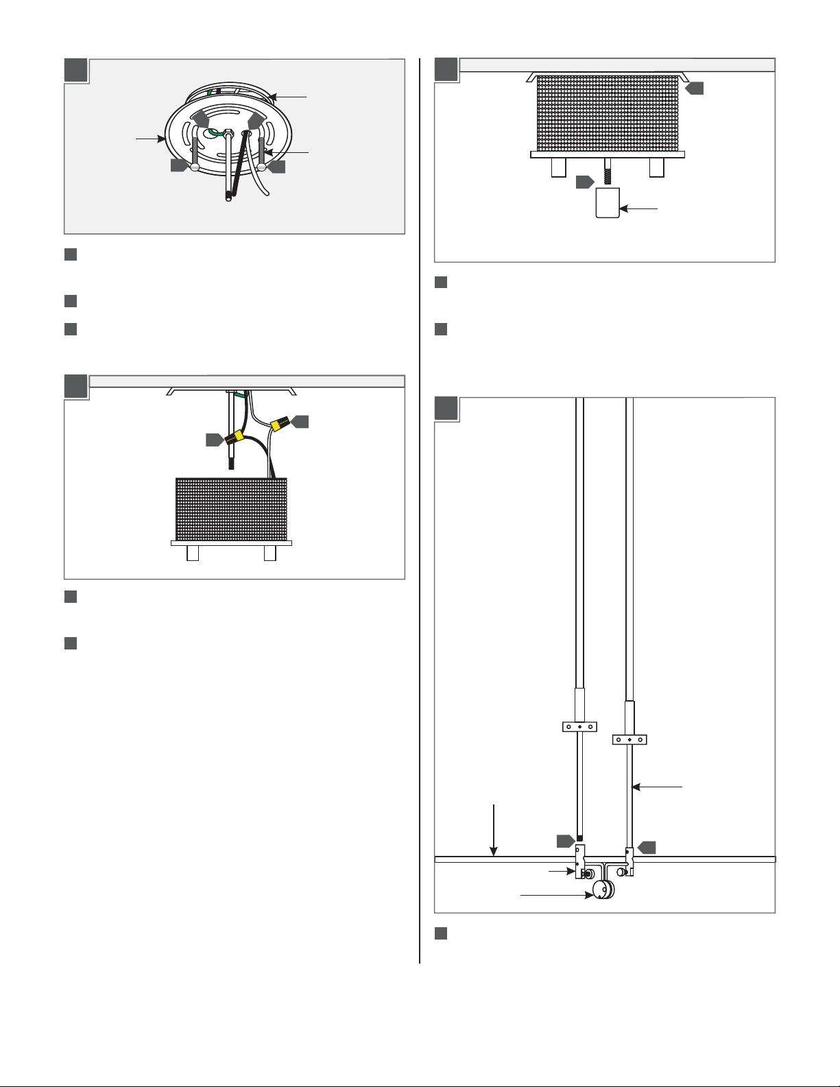
1C
ELECTRICAL
BOX
3
BACKPLATE
5
3
Make sure the backplate is grounded in accordance with local
electrical codes.
4
Feed the power wires through the backplate side hole.
4
#8-32 SCREW
5
1E
9
CAP NUT
8
Place all wires and wire nut connections properly inside
the canopy.
8
5
Mount the backplate to the electrical box with two #8-32
screws.
1D
6
7
6
Connect the canopy white wire to the neutral power line wire
with a wire nut.
7
Connect the canopy black wire to the hot power line wire
with a wire nut.
9
Slide the canopy center hole onto the threaded rod. Replace
and completely tighten the cap nut to secure the canopy in
place.
1F
SUSPENSION
SOCKET RAIL
10
SOCKET POST
SOCKET
10
Screw the two suspension rods completely into the middle
10
ROD
socket posts.
2
Page 3

Install the lamps
1G
SUSPENSION ROD
2 MM ALLEN WRENCH
CROSS METAL ARM
11
Hook one end of the cross metal arm to the socket post and
hook the other end to the suspension rod post.Tighten the
M4 set screw on the suspension rod post with the provided
2mm Allen wrench. Repeat this step for the other cross metal
arm.
1H
2A
M3 SET SCREW
SOCKET
1.5 MM ALLEN
WRENCH
NOTE:To reduce the risk of a burn or electric shock
during relamping, disconnect the power to the fixture.
MAX 50
Use Watt MR16 Front Cover
Halogen Lamp With Each Socket.
1
Push the lamp pins completely into the socket holes and
tighten the two M3 set screws with the 1.5mm Allen wrench to
secure the lamp in place.
LAMP
M4 SET
SCREW
2 MM ALLEN
WRENCH
13
13
CANOPY POWER
POST
SUSPENSION
RODS
NOTE:It is recommended that one person hold the
chandelier while the electrician finishes the installation.
12
Measure the distance between the canopy power posts and
the desired height of the chandelier. Measure and mark this
distance on the suspension rods, and cut the suspension rods
with a hacksaw.
2B
2
2
THUMB
SCREW
GLASS
SHADE
2
Slide the glass shade up into the socket post and secure it in
place by tightening the two thumb screws.
NOTE:DO NOT OVERTIGHTEN the thumb screws
which may cause the glass shade to break.
SOCKET
POST
13
Insert the rods completely into the canopy power posts and
tighten the four M4 set screws with the 2mm Allen wrench.
3
Repeat steps 1 & 2 for the remaining sockets.
3
Page 4

SAVETHESE INSTRUCTIONS!
7400 Linder Ave, Skokie, IL 60077
800.323.3226 - 847.626.6300
www.lbllighting.com
© 2014 LBL Lighting.All rights reserved. The "LBL Lighting" graphic is a
registered trademark of LBL Lighting. LBL Lighting reserves the right to
change specifications for product improvements without notification.
4
A Generation Brands Company
 Loading...