

Page 1
18-11-26-REV-A
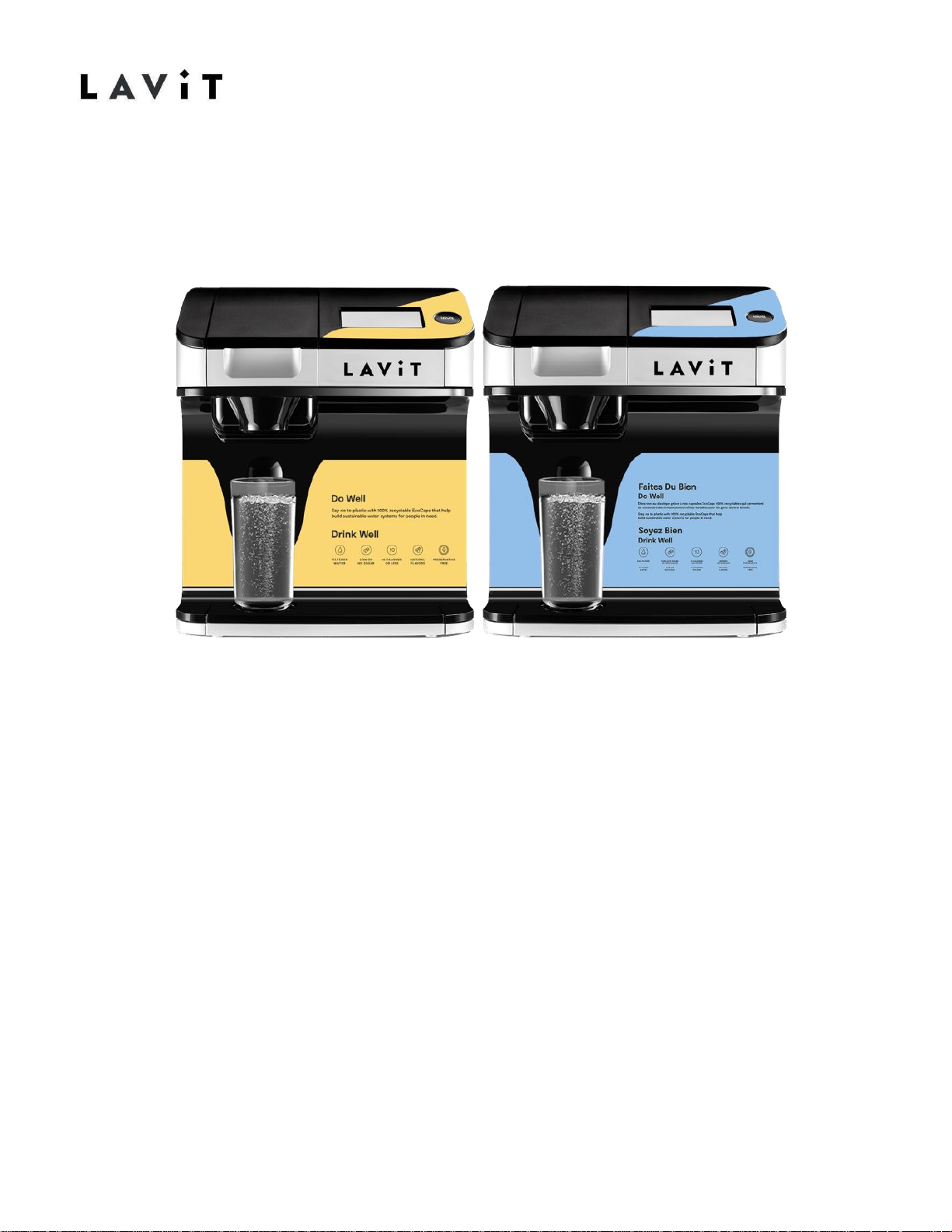
Troubleshooting Guide LB115
Series Lavit Dispenser
FOR TECHNICAL ASSISTANCE
PLEASE CALL 1.855.750.5377
Page 2

18-11-26-REV-A
Table of Contents
Page 1. Introduction
Page 2. Water Flow Diagram
Page 3-4 Electrical Diagrams
Page 5. Beverage Dispense Splatters/Multiple
Streams Page 6-7 “Clean Brewer” Screen Appears
Page 8. “Close Brewer Lid” Error when Brewer lid is
Closed Page 9. “Possible Water Leak” Error Screen
Page 10. No Soda Water – Gas Only
Page 11-13 Troubleshooting the Soda Water Circuit
Page 14 -16 Replacing the Soda Probe
Page 17-18 Soda Solenoid Valve Replacement
Page 19. No Still Water Dispense
Page 20-23 Water Stream Calibration
Page 24 -25 Water Tanks Not Filling at Start Up
Page 26- 27 Water Run On
Page 28 Blank or Black Touchscreen
Page 29 All white touch screen
Page 30 Touch Screen Calibration
Page 31 Water Chilling Screen
Page 32 Unit not Cooling or Chilling
Page 33-35 Basic Troubleshooting
Page 36 Large Amount of water left in Capsule
Page 37-38 Lavit Quick installation guide
Page 39 Lavit User Guide
Page 40 Draining & Decommission
Page 3
1
18-11-26-REV-A
Introduction
The purpose of this manual in conjunction with the LB115 Series service manual
is to ensure that technicians are provided with the necessary information and
instruction needed to address any concern or issues that may come up during
the life of the Lavit Beverage Dispenser.
“DID YOU KNOW”
All our technical documents and videos can be accessed anywhere using your
smart phone, Tablet, Lap Top or PC. See instructions below!
Go to https://www.drinklavit.com/ Click on support when the drop down comes
up select Technical then type in the password aluminum. Here you can find our
Field Service Technical solutions manual, technical bulletins, parts and service
manuals and our technical Video.
FOR TECHNICAL ASSISTANCE
PLEASE CALL 1.855.750.5377
Page 4
2
18-11-26-REV-A
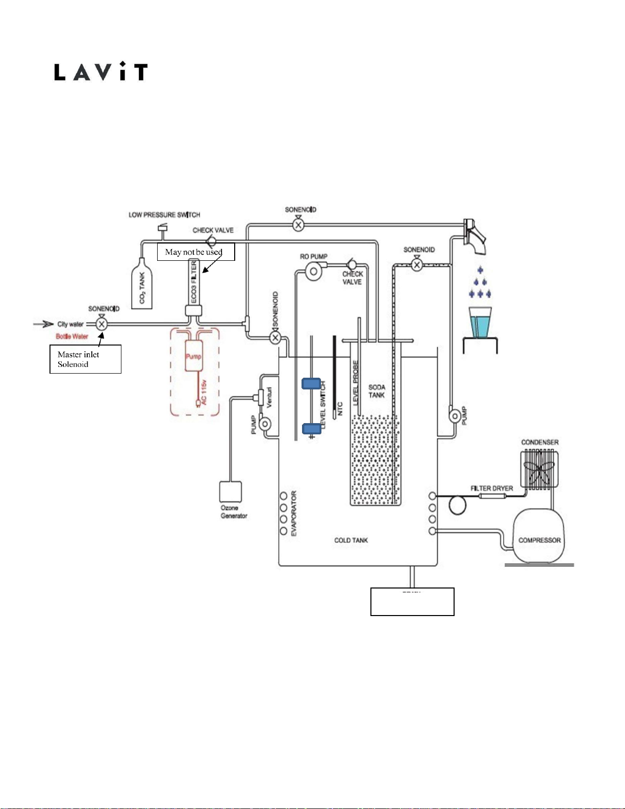
Water Flow Diagram
COLD TANK
DRIAN
Page 5
3
18-11-26-REV-A
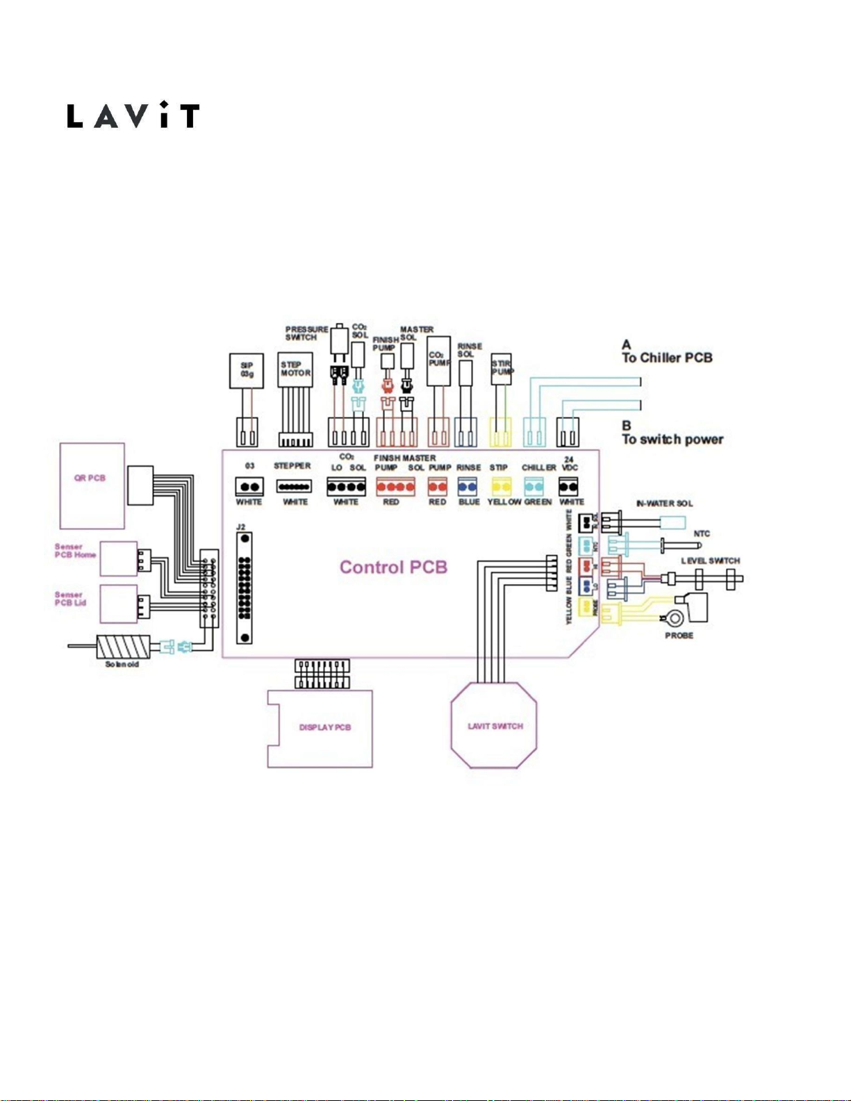
PCB Electrical Diagram
Page 6
4
18-11-26-REV-A
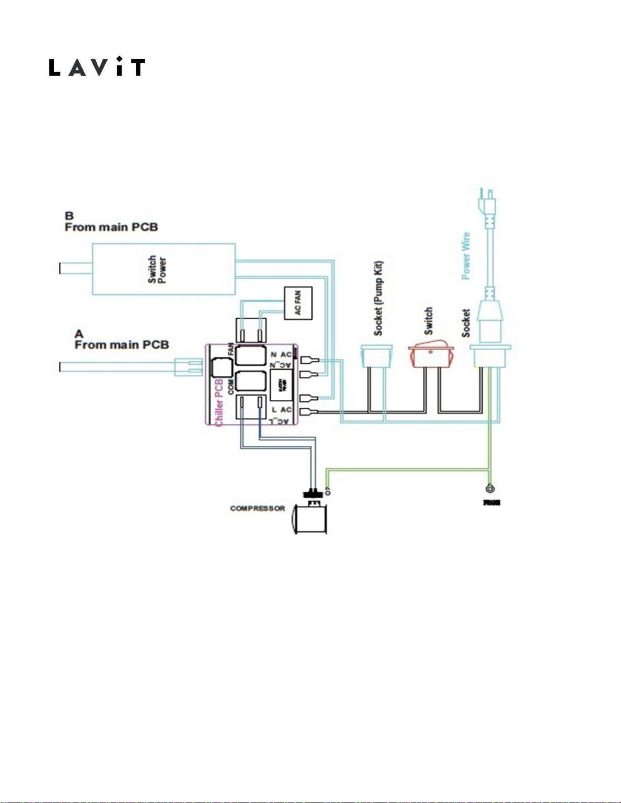
Cooler Electrical Diagram
Page 7
5
18-11-26-REV-A
4.
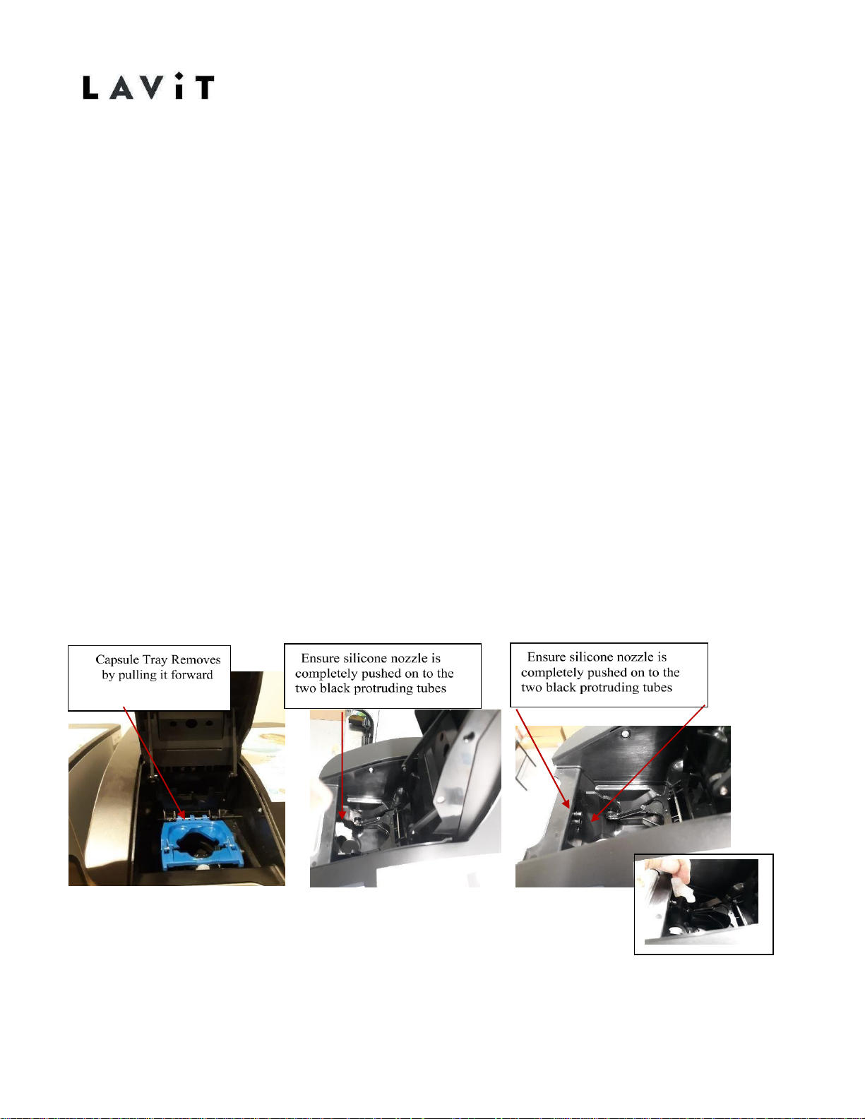
Beverage Dispense Splatters/Multiple Streams
Issue:
When crafting a Lavit beverage the dispense stream is broken up and several streams
may be present and the cup may overflow.
Solution:
This situation is usually the result of one of the conditions below.
1.
Verify that the silicone nozzle inside the brewer is present and that itis
firmly attached to the water outlet fittings.
2.
If water is also present in the capsule after the dispense cycle then
recalibrate the mix stream. Recalibrate other streams if
necessary.
3.
Clean the chamber and verify the full rotation of the capsule lifting
mechanism. Remove the capsule tray. Pull the linkage attached to the top
of the chamber towards you. Reach down under the linkage and grasp the
capsule lifting mechanism (solid black plastic with a semi-circle cut out).
Rotate the mechanism forward to a full 90-degree position. Push
mechanism all the way back and repeat 3 times ensuring it moves freely.
Page 8
6
18-11-26-REV-A
“Clean Brewer” Screen Appears
Issue:
When using the unit, the Clean Brewer screen appears.
Solution:
There are two reasons why the "Clean Brewer Screen” appears.
1.
The brewer is designed so that after a beverage is brewed the capsule lifting
mechanism returns fully to the “Home” position. A Hall Sensor is installed in
the unit to verify that the mechanism has returned Home. If the mechanism
does not return to Home then the Clean Brewer screen is displayed. The
normal cause for this to occur is that there has been a beverage build up in
the chamber preventing the mechanism to fully return to Home. Follow the
cleaning instructions to clean the brewer.
2.
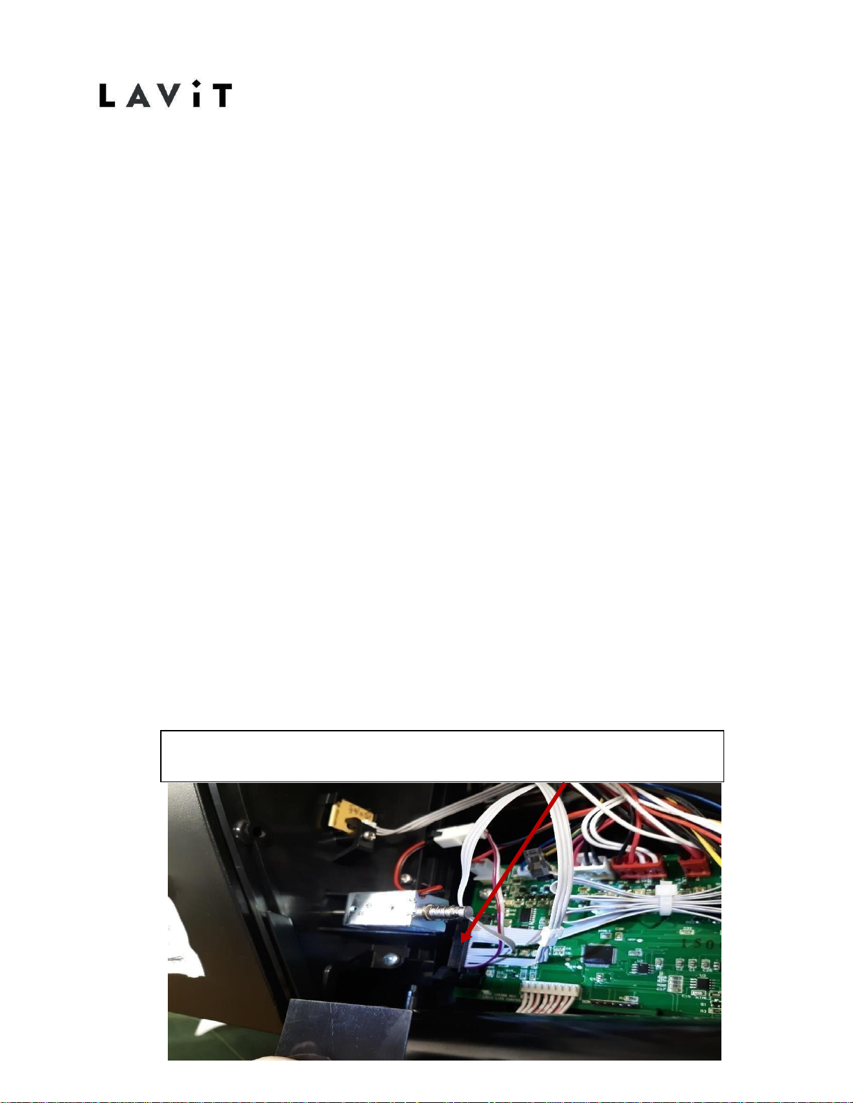
The second reason the Clean Brewer screen will appear is due to afaulty Hall
Sensor or faulty connection. Remove the lid of the unit. Locate the main PCB
under the black plastic shield on the front right of the unit. On the far left of the
main PCB locate the black connector attached to the ribbon cable. Ensure the
black connector is properly seated onto the main PCB. Remove, reinstall, and
ensure the two locks are secure. If that does not resolve the issue, follow the
ribbon lead going to the back bottom of the brewer. Locate the secondary
connection to the Hall Sensor. Ensure that the secondary connection is
properly seated. If that does not resolve the issue then replace the Home Hall
Sensor located in the brewer gearbox.
ALWAYS- Check the connections on the Main PCB. Ensure the black ribbon connector with
the grey wires are properly snapped in place. It is a good practice is to remove and reset
this connection, ensuring the side clips are properly snapped in place
Page 9
7
18-11-26-REV-A
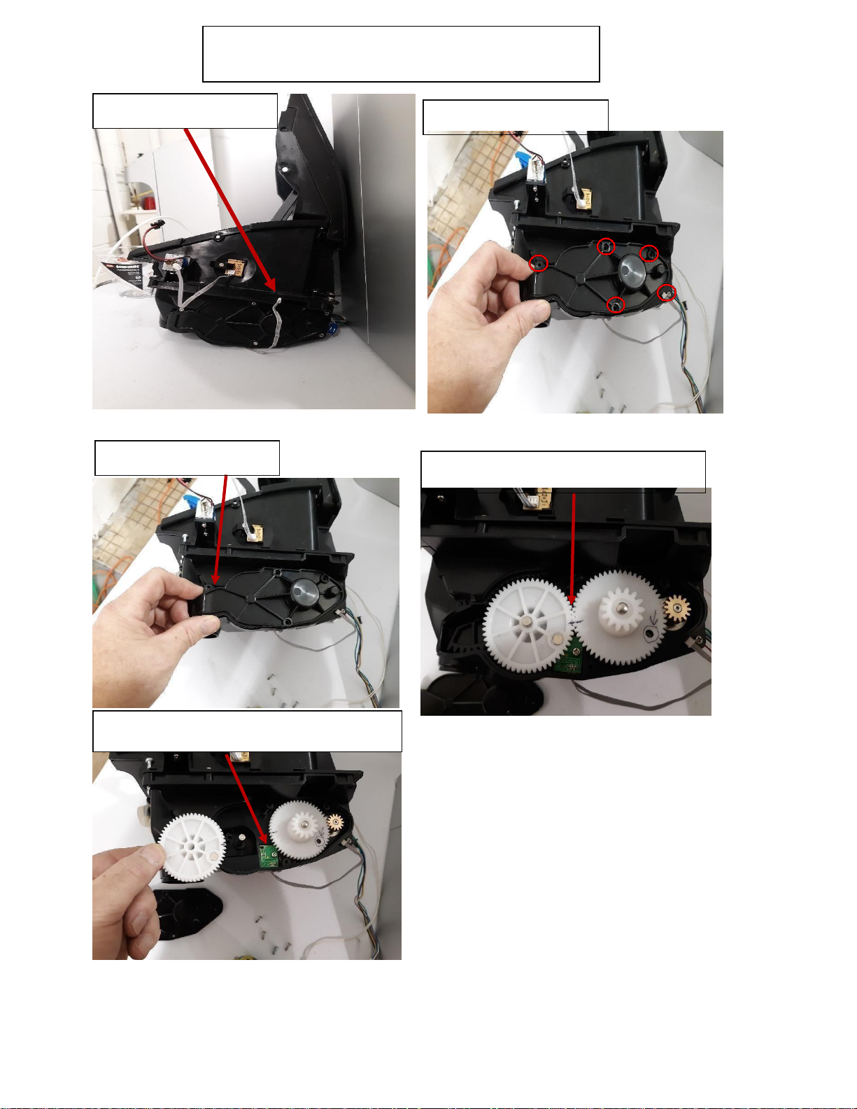
Re-install all components in reverse
order and test all functions
Reference pictures for changing the Brew
Chamber Hall/Home sensor
Check Hall Sensor Connection
Remove 5-#1 Philips screws
Mark Gears to ensure proper placement when
re-installing.
Remove Gear Cover
Remove Gear to gain access to Hall Sensor.
Remove 1-#1 Philips screw to change sensor.
Page 10
8
18-11-26-REV-A
“Close Brewer Lid” Error when Brewer Closed
Issue:
The touchscreen displays a "Close Brewer" message but the brewer lid is in
the closed position.
Solution:
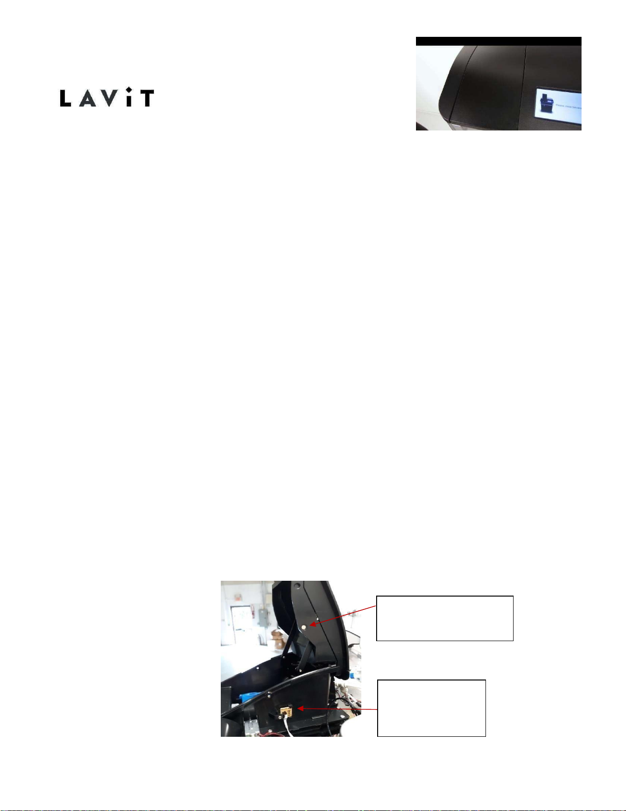
The close brewer message will be displayed when the brewer lid is closed
under three circumstances:
1. Ensure that the brewer magnet is present. Open the brewer and locate the
magnet on the right hand outside wall on the brewer lid. It will be a small
1/4" metallic disc pressed into the external side wall. If the magnet is not
present insert a replacement.
2. The ribbon connector is loose on the main PCB. Remove the top panel
cover. Pull back the plastic cover over the main PCB located on the front
right of the unit. Verify that the black ribbon connector on the far left of
the PCB is firmly attached and the two locks are in place. Disconnect and
reconnect as necessary.
3. If neither of the above clear the error check the Hall Sensor connection to
the ribbon cable. With the top panel removed locate the magnet and Hall
Sensor attached to the external wall of the brewer 1
st
ensure the magnet
is in place. If not replace it. Then make sure the sensor lead is properly
connected to the main ribbon cable. If it is and the error remains then
replace the Hall Sensor
Magnet- this activates
the Hall sensor when lid
is closed
Hall Sensor. This let
the board know if
the lid is open or
closed
Page 11
“Possible Water Leak” Error Screen
Issue:
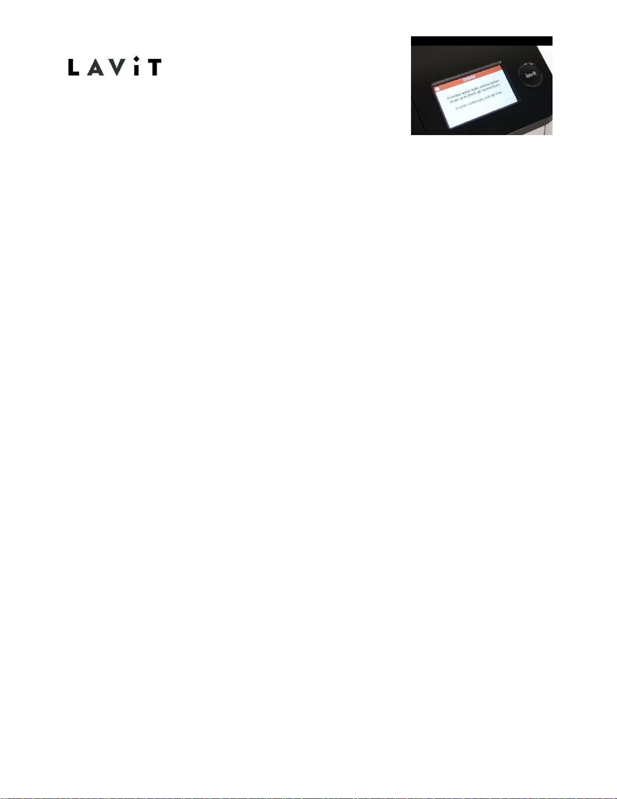
During start up or during normal operation the unit will display "A Possible Water
Leak" error message screen.
Solution:
This error message appears when the inlet solenoid to the unit has been open
for more than five minutes. Under normal circumstances tank filling or refilling
should not take more than five minutes. If there was a major water leak inside
the unit then the unit would shut down until a repair is made. A false error
message will occur under the following circumstances:
1.
A plumbed in unit with low inlet water pressure. If the water pressure
going into the unit is less than 30 psi then the 5-minute cycle could time
out and the error message will appear. Turn unit off and restart to clear the
error. Dispense a cup of water to reopen the inlet solenoid. This may
happen frequently during a new install since the amount of water
necessary to fill the tanks may exceed the inlet water line's capacity of 5
minutes. Restart and clear error. Dispense water to o p e n solenoids.
2.
A bottled water unit with a Flo-Jet or Lavit pump will show this error if the
bottle is empty or the pump is not on. Check to make sure your water
bottle has adequate water remaining in it and that the pump is powered on.
Replace bottle water if needed. Turn off the unit and restart. Dispense two
cups of water making sure the pump is on. This will clear any air blocks in
the line and the tanks should refill as normal.
3.
The water tanks are not filling due to a solenoid or float issue. See Water
Tanks
Not Filling at Start Up Page 24-25 in this manual.
9
18-11-26-REV-A
Page 12
18-11-26-REV-A
No Soda Water – Gas Only
Issue:
When the user selects soda water or a soda beverage no soda water is
dispensed just CO2 gas. This mayhappen all the time or on occasion.
Solution:
The soda tank is not refilling properly. There may be an air lock in the inlet
water line to the soda tank which the soda pump cannot overcome.
This usually happens on the installation of a unit when the tech turns the CO2
gas on before allowing the soda pump to start pumping water into the soda
tank. To resolve:
1.
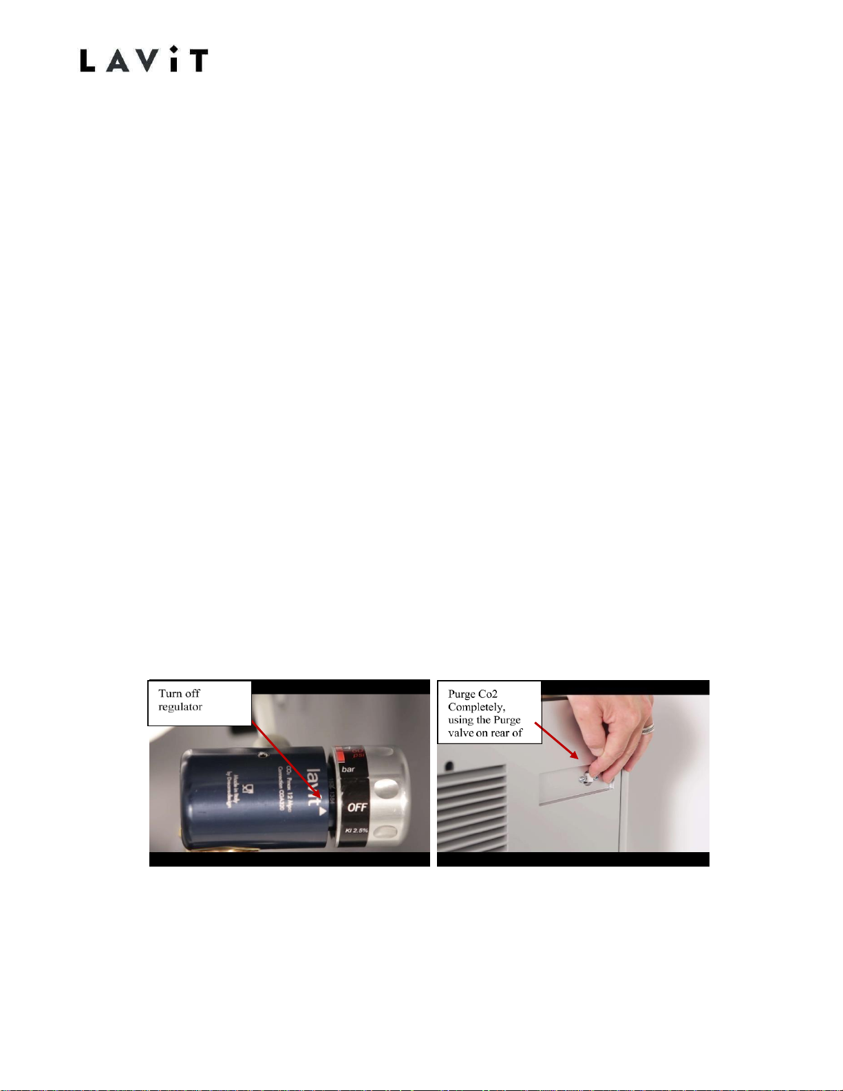
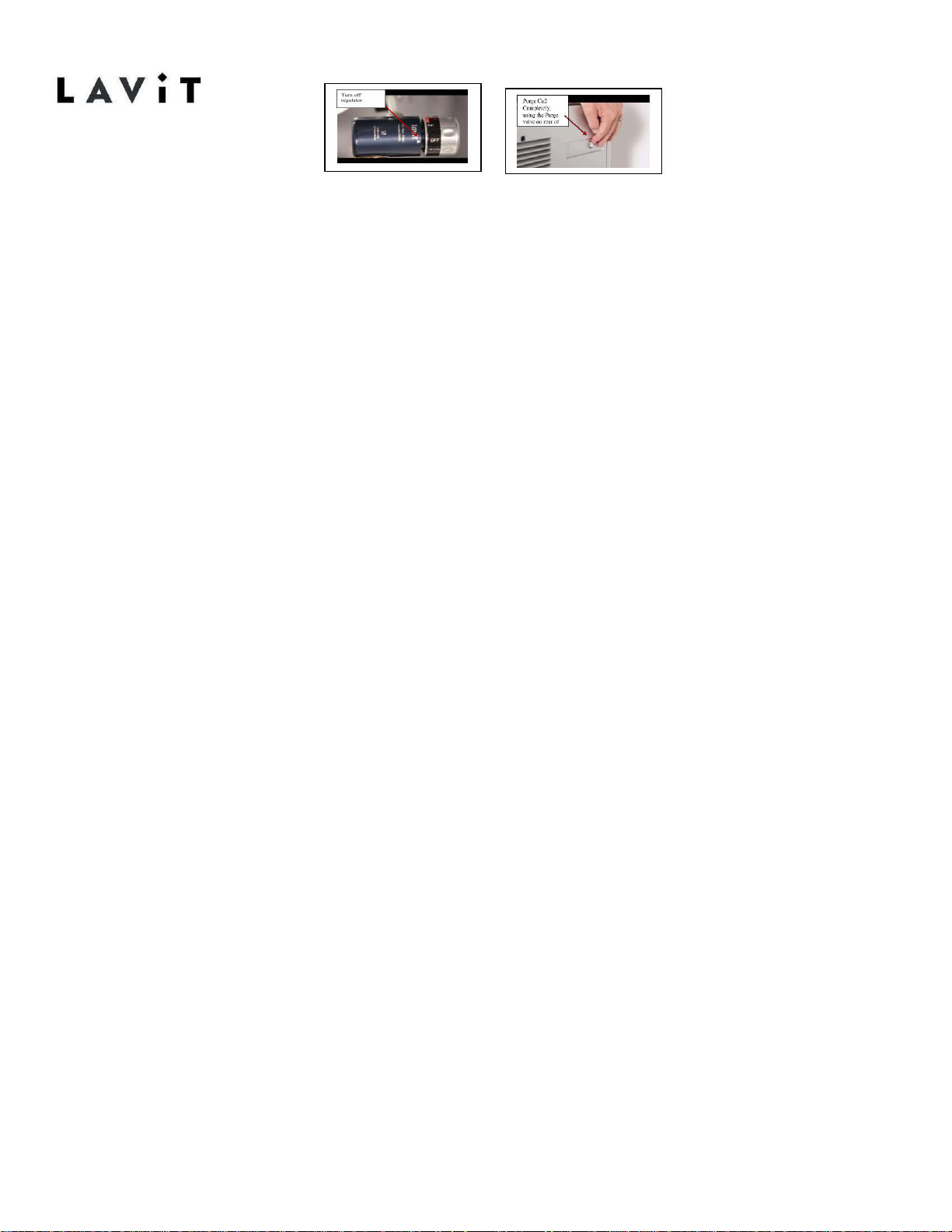
Turn off the regulator
2.
Relieve all gas pressure thru the purge v a l v e
3.
Turn off and restart u n i t
4.
Dispense a full cup of cold-water
5.
Let the soda pump refill the tank (5 to 7 minutes)
6.
Turn on CO2.
7.
Before going on with trouble shooting try the above process once
more.
8.
If this does not correct the issue follow trouble shooting the soda
circuit on pages
10
Page 13
18-11-26-REV-A
Troubleshooting the Soda Water Circuit
Problem:
When a user selects sparkling water, the unit dispenses just CO2 gas. This may happen
periodically or it may happen continuously.
Issue:
The soda tank is not refilling properly when the water level in the tank is low. Root
Cause:
Air block in the soda water inlet line or a faulty soda level probe circuit.
Troubleshooting Procedure:
1. Remove the top cover panel but keep the touchscreen
and Lavit button connectors attached.
2. On the main PCB located on the front right of the unit under the
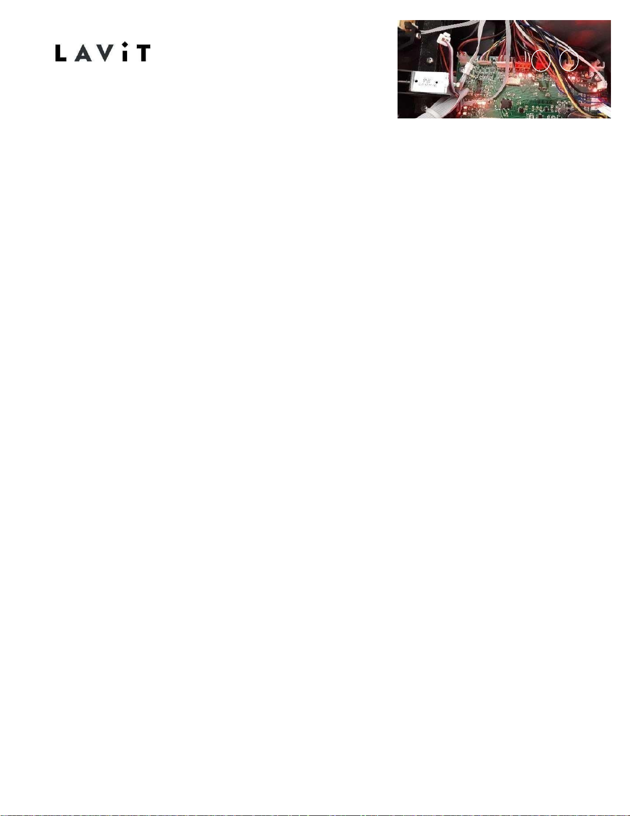
plastic shield, locate the soda probe lead connector. The connector
will be the yellow connector found on the front right-hand side of the
unit closest to you. It will have a yellow and black wire attached.
3. Locate the soda pump connector. The connector will be a red
connector along the top of the PCB located in the middle
(5
th
from right or left). It will have a red and black wire
attached.
4. Inboard to the soda pump connector on the PCB a RED LED
illuminates when power is applied to the Soda Pump. Dispense two
medium soda waters. Watch to see if the RED LED illuminates. If the
RED LED does not illuminate proceed to STEP12.
5. If the RED LED comes on verify that water is being pumped to the
soda tank. This can be verified by the cycling on and off of the inlet
and cold tank solenoids which will also have RED LEDs cycling on
and off as well.
6. If the soda pump RED LED is illuminated and not cycling on
and off of the solenoids then an air block is present.
11
Page 14
12
18-11-26-REV-A
7.
Turn the CO2 regulator to off by turning counter clockwise until the knob
cannot turn any more. Ignore the “Off” on the regulator label. Turn past
that to fully turn the pressure off.
8.
Relieve all gas from the system by opening the purge valve on
the upper rear of the unit.
9.
Turn the unit off. Power the unit on. Dispense a half of cup
of still water by pressing the Lavit Button.
10.
Verify that the soda pump comes on (RED LED illuminates). Verify that
they water is flowing to the soda tank (Inlet and Cold Tank Solenoid RED
LEDs cycle on and off.
11.
Once the soda tank fills (soda pump RED LED will turn off), set the CO2
pressure to 3.5 bar. Dispense two medium soda waters to ensure that the
soda pump comes on and water is being pumped into the soda tank.
Proceed to Step23.
12.
Disconnect the yellow soda probe connector. Verify that the soda pump
comes on (RED LED will illuminate). Verify that water is being pumped into
the soda tank by watching for the Inlet and Cold-Water tank solenoids
cycle on and off (RED LEDs will illuminate). Reconnect the connector.
Verify that the soda pump immediately turnoff.
13.
Dispense two medium soda waters. If the soda pump does not
power on then a faulty soda probe circuit exists. Power the unit off.
14.
Remove the ozonator from the top of the cold tank (Blackbox
connected by 4 screws).
15.
Locate the yellow wire leading to the spade connector attached to
the probe. Disconnect the spade connector.
16.
Cut away the insulation foam around the probe and save the
insulation.
17.
Using an 11/16” socket unscrew the probe. Use pliers if a socket is not
available.
18.
Remove the O-ring gasket from the old probe and place on the
replacement probe if the replacement probe does not have an Or i n g .
Page 15

13
18-11-26-REV-A
19.
Install the replacement probe. Replace the foam insulation.
20.
Reconnect the spade connector.
21.
Reinstall the ozonator.
22.
Power on the unit. Dispense a half cup of still water.
Verify that the soda pump comes on and that the soda
pump is pumping water.
23.
Reinstall the top cover panel.
Page 16
14
18-11-26-REV-A
Replacing the Soda Probe
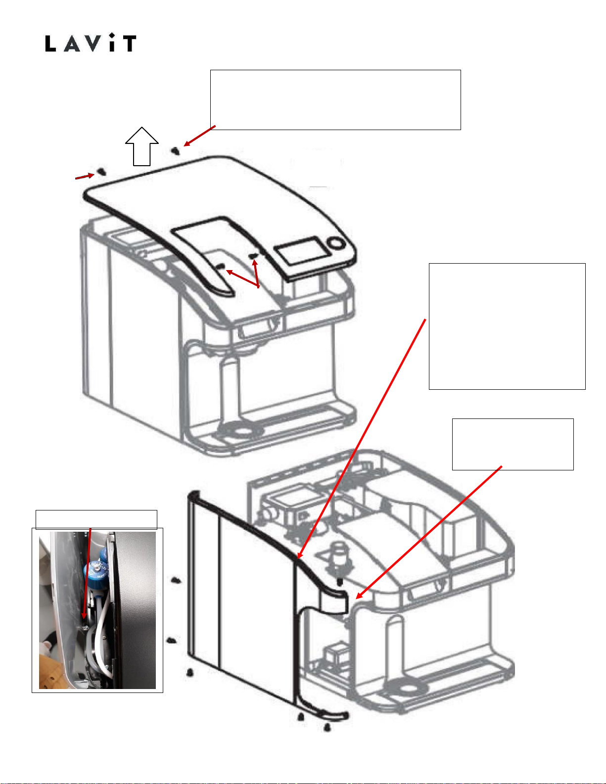
Pic # 1
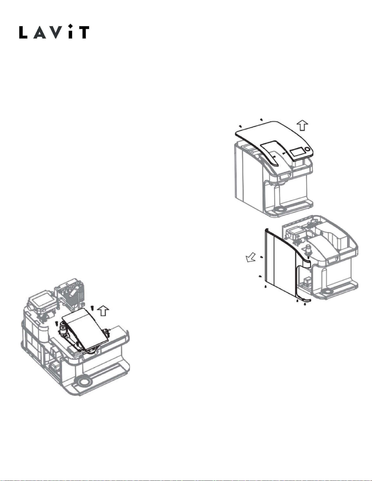
Step -1 Open the beverage lid remove the 4screws shown below. Then lifting upwards in
the center rear section of the top cover,
unsnap and remove top cover
Step -2 Remove all Screws
shown in diagram below.
Then Look Over top edge of
panel to locate the internal
side panels crew Using Long #
2 Phillips bit remove screw
before removing side cover.
See Pic # 1
Release plastic snap
before removing side
cover
Page 17
15
18-11-26-REV-A
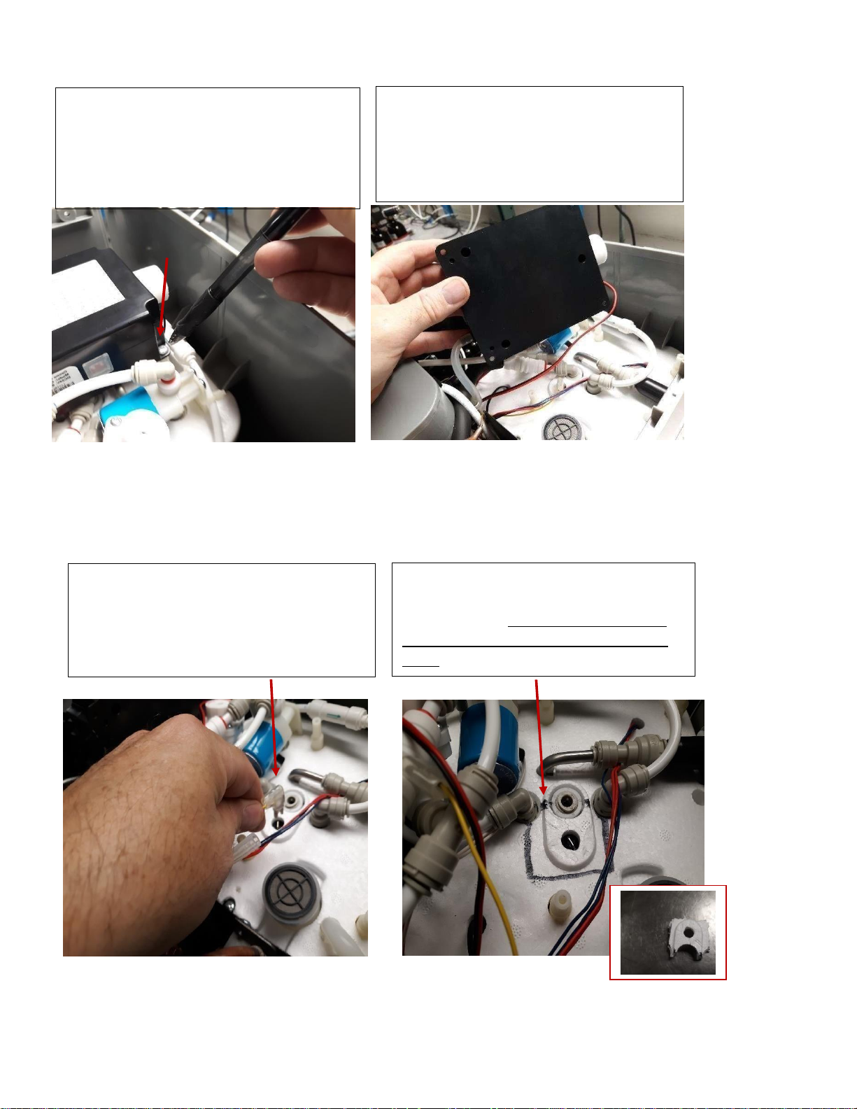
Step – 5 Expose the soda probe head
by cutting out the polystyrene as
marked below .DO NOT DISCARD!! IT
MUST BE REPLACED Remove and set
aside
Step -4 Disconnect the Soda
probe connection.
Step 2 -Remove the four screws, one
on each corner holding 03 Generator/
Ozonator in place.
The 03 Generator/ Ozonator assembly
is located at rear of cooling tank
Step – 3 tilt the 03 Generator/
Ozonator assembly to the one side
Page 18
16
18-11-26-REV-A
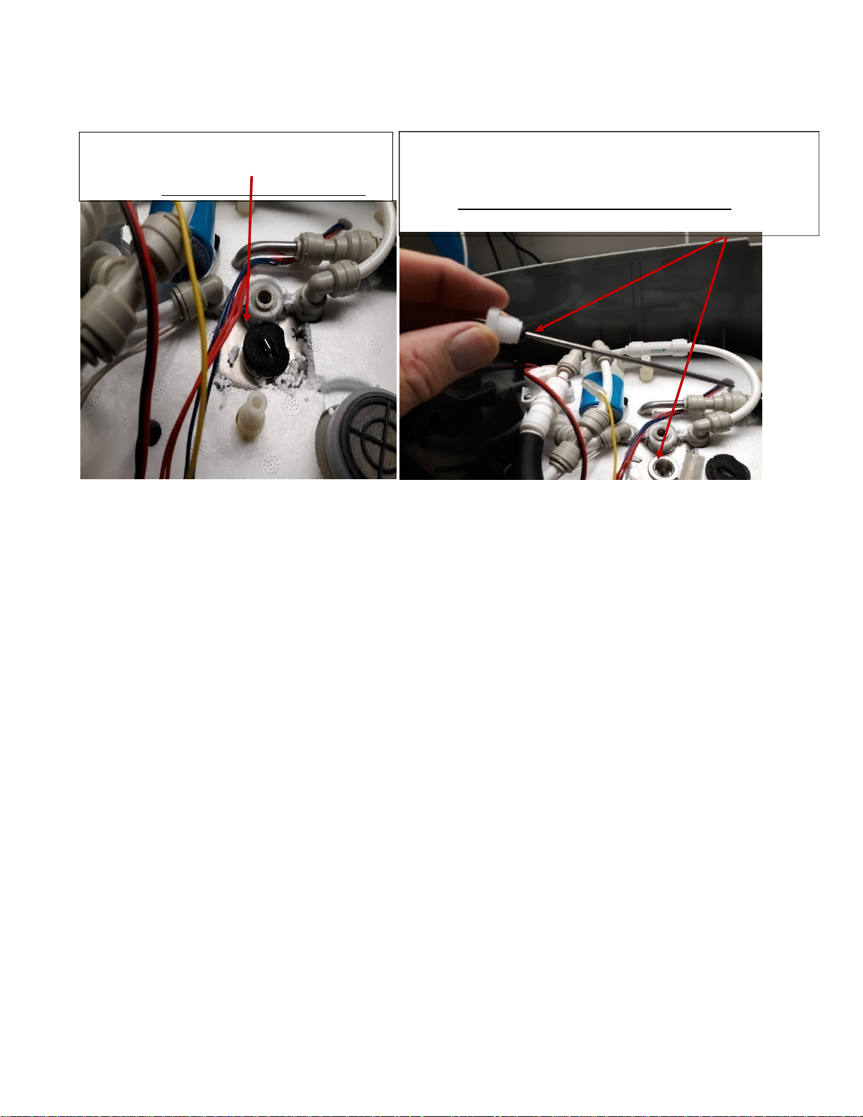
FINAL STEP -Replace probe, replace polystyrene and secure it with a non-conductive tape,
white duct tape is preferred, then reassemble in reverse order.
Step -6 After removing polystyrene
Remove black probe cover and set
aside and clear any Polystyrene debris.
Step -7 Gently unscrew soda probe and replace. Soda
probeheadisanM17.
NOTE: Be careful not to lose black O-ring seal, it may
remain in the tank opening, if so remove and place it
back on the probe
Page 19
17
18-11-26-REV-A
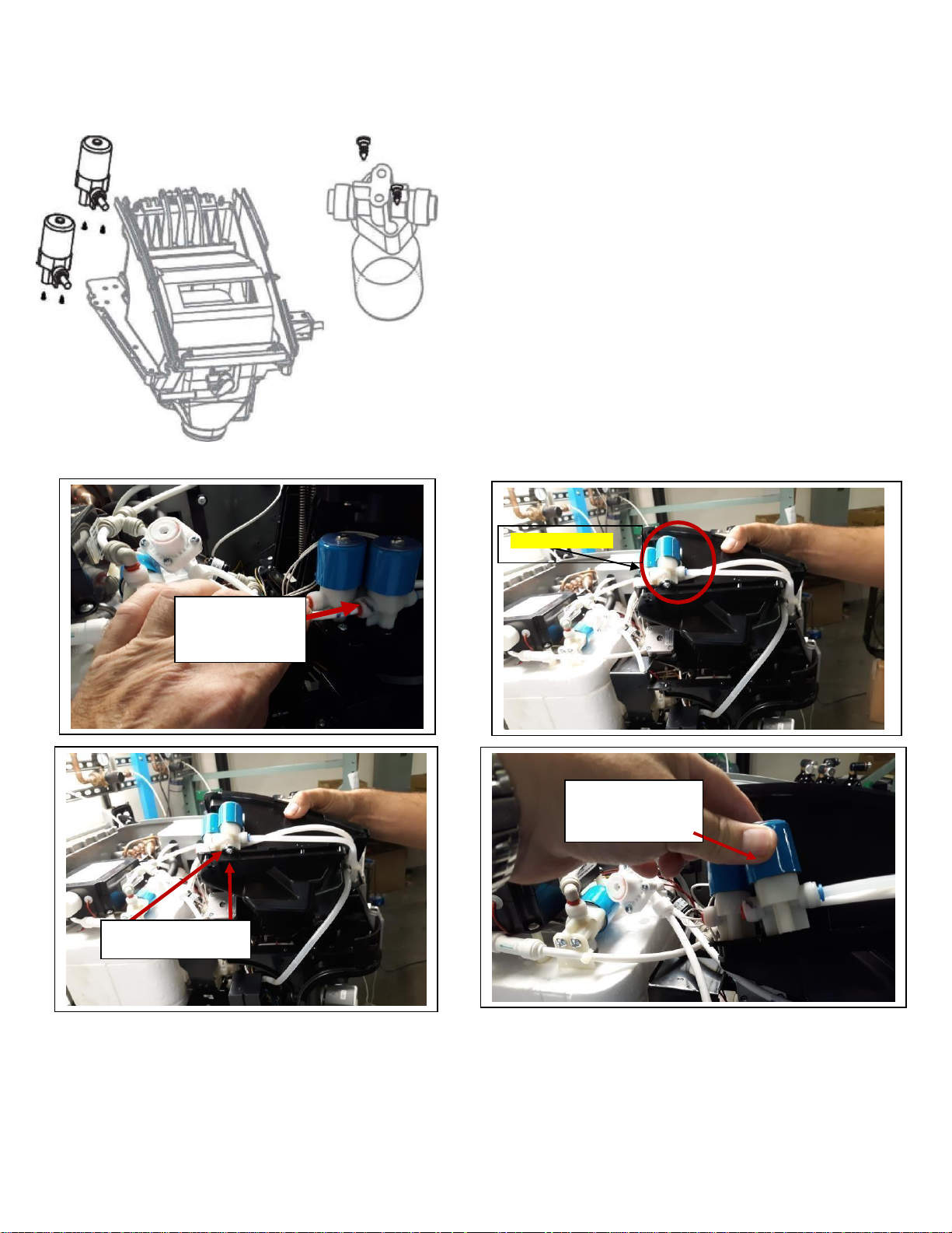
Soda Solenoid Replacement
If the soda valve is continually dripping it may be due to a piece of sediment trapped on the
plunger seal of the valve and stopping it from sealing shut. To confirm the soda valve is
dripping, first vend a still water, then turn off the water supply to the machine, then power
down the machine, and make sure the C02 regulator is turned on. If the soda water is
continually dripping for a minute then it is not sealing correctly.
1)
The soda valve is mounted on the left-hand side of the brewer and is the valve nearest to front (the front valve)
2)
The valve needs to be stripped to gain access to the plunger
seal where there may be a piece of sediment.
3)
To do this you need to remove the valve and do the following.
4)
Power down, turn off the water supply, turn off the C02
regulator, and release the pressure in the soda tank by
actuating the purge valve mounted on the rear of the
machine.
5)
Remove the top cover. 2 screws at the back and 2 screws
on the side wall of the brewer. Disconnect the LCD and the
push button cable plugs
6)
Remove the left-hand side panel, release the 3 screws at
the base, 1 screw on inside of panel near the brewer, two
screws on the rear panel, and a push clip on the rounded
front part of the panel.
7)
The solenoid is held in place by 2 screws from base.
8) To gain access to the 2
screws you need to loosen
the 4-screws holding t he
brewer and tilt it on its side gently.
9) Undo the solenoid.
10) Purge the C02 again before you remove the
soda water line. This line is pressurized so always turn
off C02 and purge before disconnection. The line will
drip as the soda water expand.
11) Remove the solenoid enough to gain access to
the base.
12) On the underside in two recessed holes are two
small retaining screws that hold the valve bonnet in
place.
Page 20
18
18-11-26-REV-A
12)
Remove these two screws and the bonnet will now come off of the valve’s plastic body. Take care the plunger and spring do not fallout.
13)
Look in the valve body outlet orifice and
the valve plunger seal for a small piece of
sediment that would have stopped the
plunger seal mating correctly with the valve
body.
14)
Reassemble in reverse order.
15) Turn on C02, water and power and
test for function or any leaks.
Remove Soda
Solenoid valve
tubing
Soda Solenoid valve
Remove the two screws
Remove Soda
Solenoid valve
assembly
Page 21
19
18-11-26-REV-A
No Still Water Dispense
Issue:
The unit will not dispense cold still water nor create a still water beverage. Soda water
dispense is normal.
Solution:
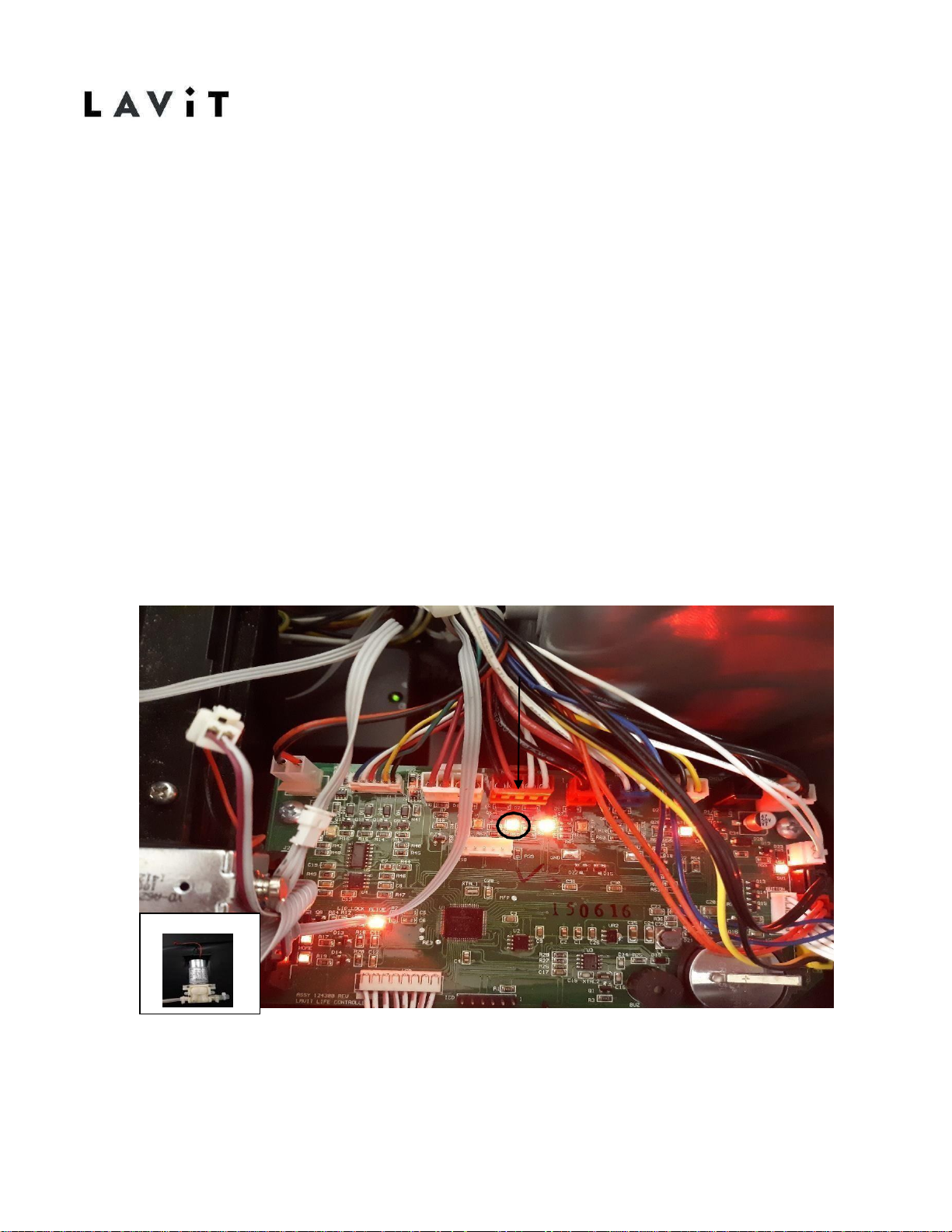
This condition is due to a faulty still water pump or still water pump connection. Remove
the top of the unit keeping the connectors attached. Observe the main PCB and the 4th
connector from the left on the top row of connectors (a red connector with dual leads
- two white and a red and black). Press and hold the Lavit button. A red light should
illuminate on the main PCB next to the connector indicating power to the dispense
pump. If the light does not illuminate then replace the main PCB. If the light does
illuminate ensure that the red connector is properly seated on the main PCB. Follow
the red and black leads back towards the dispense pump and locate the secondary
connection. Ensure that connection is properly seated. If the pump does not power on
after checking the PCB and connections replace the dispense pump.
Still Water pump
Page 22
20
18-11-26-REV-A
Water Stream Calibration
EACH LAVIT BEVERAGE DISPENSER INSTALLED IN A CUSTOMER LOCATION SHOULD
BE CALIBRATED DURING THE INSTALLATION PROCESS TO ENSURE THAT PROPER
WATER AND BEVERAGE VOLUMES ARE DISPENSED. The Lavit
Beverage Capsule is sized to deliver 12-ounce beverages. It is important to deliver 12ounce beverages to maximize customer satisfaction with the beverage taste. Too little
water will produce overly sweet and intense beverage flavor. Too much water will
deliver weak and watery beverages.
It is critical that 12-ounce beverages be served each time. To properly calibrate the Lavit
Dispenser, three water streams must be calibrated: mix, still, and sparkling. During the
calibration process 12 ounces of water should be drawn from the dispenser for each
calibration. The unit’s software determines the amount of time it takes for the 12 ounces
to be dispensed for each stream. The software then sets the proper time sequence to
deliver 7 and 12-ounce water servings and 12-ounce beverage servings.
The entire calibration process should take no more than five (5) minutes.
Required Materials and Tools
Measuring Cup or Beaker – marked for 12 oz. or 355 ml
Optional weight Scale – (Food scales are available in most department stores such as
Wal- Mart or Target)
Calibration Instructions
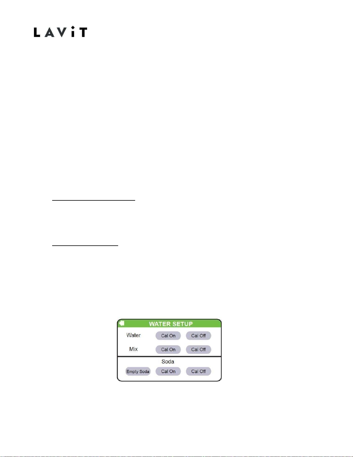
1. Open the mix chamber and remove the blue capsule tray. Close the chamber.
2. At initial startup, all the water lines should be first purged of air. Enter the WATER
SETUP screen from the SERVICE MENU screen. Your WATER SETUP screen
should be as below.
Page 23

21
18-11-26-REV-A
3. Place your measuring beaker under the water dispense.
4. Press the Water CAL ON icon. Let the still water run for about five seconds
to remove all air in the still water lines. Press the CAL OFF icon. Dispose the
water.
5. Place your measuring beaker in the dispense area and press the Water CAL
ON icon. Allow the unit to dispense 12 ounces of still water. Press the CAL
OFF icon immediately when 12 ounces are d i s p e n s e d.
6. (Optional)-Weigh your beaker of water. 12 ounces will weigh 355 grams. The
acceptable range is plus or minus 10 grams (345 g to 365 g). Repeat as
necessary to achieve a result in the target r a n g e .
7. Follow Steps 3 through Step 7 for the Mix Stream using the appropriate CAL
ON and CAL OFF icons for the Mix Stream (Purge air and then calibrate).
8. To calibrate the sparkling water stream first ensure that the CO2pressure
regulator is set to 3.5 bar or 50psi.
9. Follow Steps 3 through Step 7 for the Sparkling Stream using the appropriate
CAL ON and CAL OFF icons for the Sparkling Stream (Purge air and
calibrate).
10. After calibration has been completed return to the HOME screen by pressing
the BACK ARROW in the upper left of the touchscreen until reaching HOME.
11. Empty your measuring beaker.
12. Dispense a medium water. It should weigh 207 grams plus/minus 10g.
13. Dispense a large water. It should weigh 355 grams plus/minus 10g.
14. Dispense a sparkling water. It should weigh 207 grams plus/minus 10g.
15. If the volumes are out of range DO NOT RECALIBRATE. Proceed to the next
step.
16. Replace the blue capsule tray in the m i x chamber.
Page 24
22
18-11-26-REV-A
17. Dispense a Lavit Tea, a Lavit still water beverage, and a Lavit sparking water
beverage. Use one capsule for all beverage measurements. If available use
lemonade, lemon lime, or apple pear.
18. All selections should dispense 12-ounces or 355 grams plus/minus 10 grams
of beverages.
19. IF THE BEVERAGE VOLUMES ARE TOO HIGH OR TOO LOW THEN
RECALIBRATE THE STILL WATERORTHE SPARKLING WATER STREAMS AS
NECESSARY TO EITHER INCREASE OR DECREASE THE BEVERAGE
VOLUME.RE-CHECK YOUR BEVERAGE VOLUMES.
20. Once complete, the Lavit Dispenser will retain the settings and 12 ounces
of beverages will be served each time. See Pictures on next page for
reference.
Page 25
23
18-11-26-REV-A
Water Stream Calibration
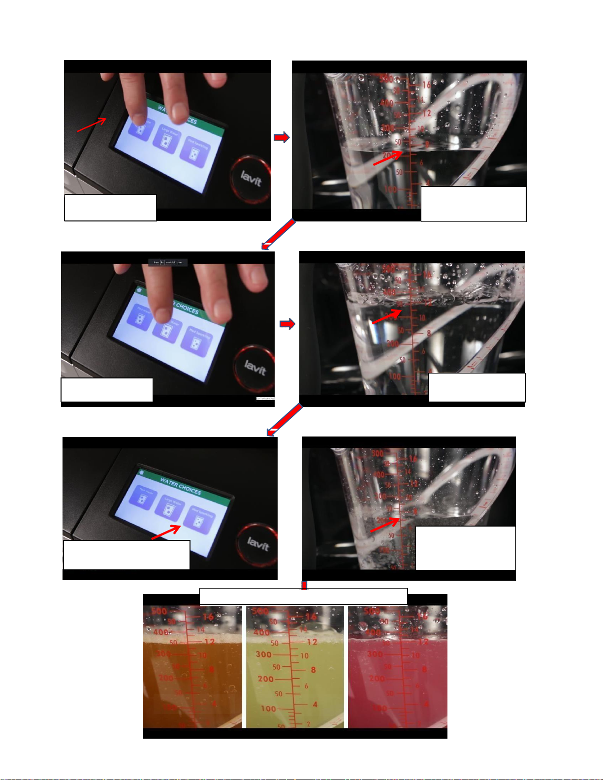
Reference Pictures
SPARKLING
Select Medium water
Measure Medium Water
Target is between 7 to
7.5 ounces
Select Large water
Measure Large Water
Target is 12 ounces
Select Medium sparkling water
Measure medium
sparkling water,
Target is between 7
to 7.5 ounces
The example below is considered normal for all
TEA
FLAVORED
Page 26
24
18-11-26-REV-A
Water Tank Not Filling at Start Up
Issue:
At initial install the water tanks will not fill.
Solution:
When the unit is powered on the touchscreen should show the following:
1.
Warming Up and software versions displayed
2.
No CO2 (because the CO2 should not be turned on at startup)
3.
Home Screen with two red icons on the bottom right of the
touchscreen (low water and low CO2pressure)
The Lavit Button should be flashing RED. Press the Lavit button firmly and the inlet
and cold tank solenoids will open and the tanks will fill. You should hear the
solenoids engage and the water running. If the above does not resolve the issue
then the inlet solenoid or the cold tank solenoid is not opening.
This can be caused by the f o l l o w i n g:
1. The inlet water pressure may be above 60 psi. High water pressure will
mechanically prevent the inlet solenoid from opening. Check the water
pressure and ensure a pressure reducer on the inlet line (40to 60 psi)
has been installed.
2. There is no power to the inlet solenoid or the cold tank solenoid. Remove the
top of the unit keeping the connectors attached. Access the main PCB by
pulling back the black plastic cover over the PCB on the front right side of
the unit. Find the 4th connector from the left on the top row of connectors (a
dual red connector with two white and a red and black wires). Also locate the
cold tank solenoid connection
(small white connector at the top of the right- hand side of the PCB). Follow
the above start up instructions. Look for red lights to illuminate next to the
red and small white connectors when the Lavit button is depressed firmly. If
no lights are illuminated or just one light then check that the connectors are
properly seated. Also follow the white leads from the red connector back
from the connector to a secondary connector. Ensure the secondary
connector is properly seated. Recheck by restarting as above.
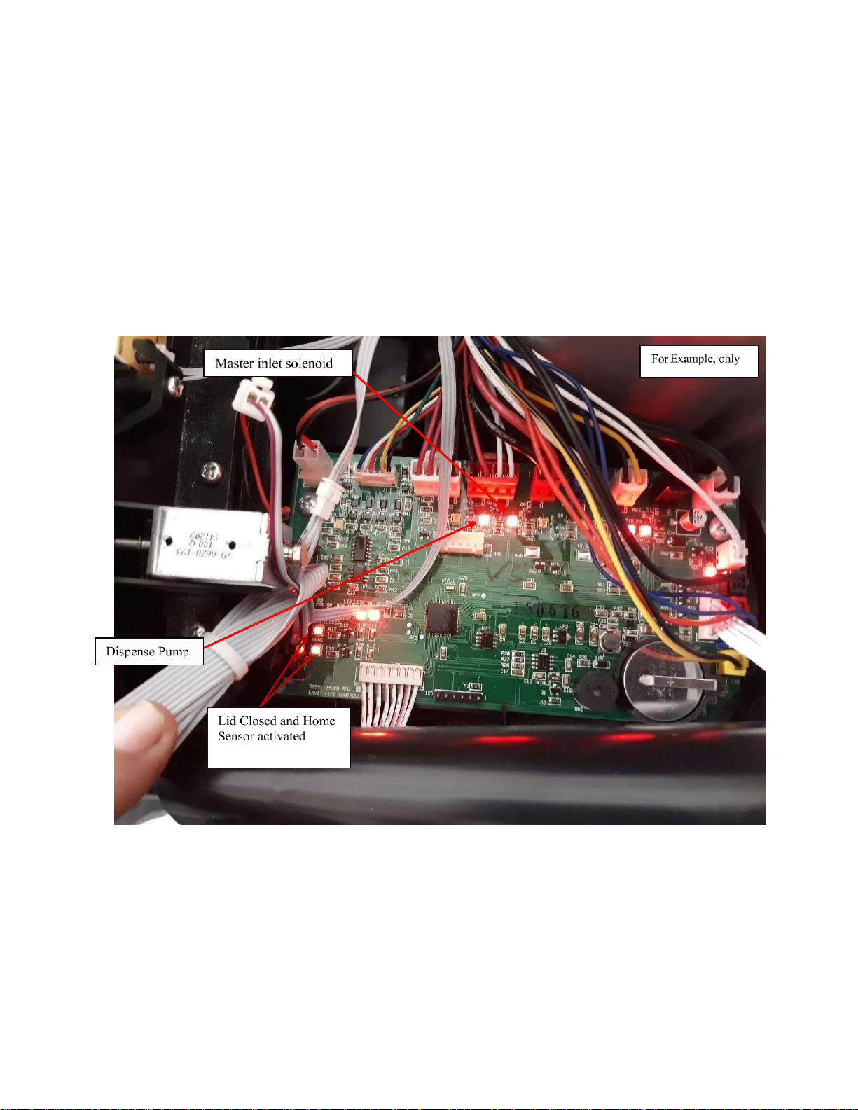
3. If the lights still do not illuminate, the electrical float mechanism in the coldwater tank may be faulty. To verify - on the right side of the PCB remove the
red connector and the white connector with the blue w ir e
Page 27
25
18-11-26-REV-A
leads. These will be the third and fourth connectors from the top on the right
side. Jump the two blue prongs in the blue connector slot on the PCB. If the
solenoid lights come on and water starts filling the tanks then the float
mechanism is faulty. Replace the float mechanism. If the lights do not
illuminate replace the main PCB.
4.
If the lights do illuminate and no water is flowing then a faulty solenoid may be
present. To determine which solenoid is faulty disconnect the inlet tubing
going into the cold tank solenoid sitting on top of the cold tank. Run the
inlet tubing into a container. Restart as above. If water flows into
container the cold tank solenoid is faulty. If no water flows into the
container then the main inlet solenoid is faulty. Replace the faulty
solenoid. Each component is marked on the board. Use the lights to
identify if the main PCB is sending a voltage signal to the necessary
components.
Page 28

26
18-11-26-REV-A
Water Run On After Dispense
Problem:
When a dispense of a beverage, soda water, or still water is finished
there is a continuous dripping of water from the dispense point.
Root Cause:
After a soda dispense or a soda water beverage is dispensed, it is
normal to have some dripping, this occurs as the soda water in the
outlet tube warms and the gas expands and pushes any water out.
But if the dripping is continuing there may be foreign material lodged
in the soda solenoid v a l v e .
Corrective Action:
1.
Verify the soda solenoid valve is the issue by 1stturningthe CO2 regulator o f f
and purging all gas pressure from the system by then holding open the purge valve on
the rear of the unit. The dripping should slow and then completely
stop. Then turn on the CO2 regulator back on to 3.5 bar pour a medium sparkling
water allow approximately 3 minutes to see if the dripping stops. If the dripping
continues follow the steps below.
2.
Power off the unit and remove the top cover completely (4 screws – 2in
the top rear and 2 inside the brewer on each internal side wall, then pull up on the
rear center of the top cover, it will snap loose. While holding the top in one hand
disconnect the ribbon connectors from the Lavit button assembly and display board.
3.
Remove the left side panel (6 screws – 2 on the rear, 3 under, 1 on the inside
wall towards the front which requires along Phillip screwdriver to reach).
4.
Relieve all gas pressure in the system by turning off the CO2
regulator and opening the purge valve until all pressures
released.
5.
Remove the inlet tubing from both the soda solenoid and the midstream
solenoid located on the left side of the brewer. The soda solenoid is the
outside solenoid. Remove the outlet tubing from the soda s o l e n o i d .
6.
Remove the four corner screws holding the brewer assembly in
place. Be careful on the right rear screw to secure the two spacer
washers.
7.
Unplug the soda solenoid from its black connector extension cable.
Page 29
27
18-11-26-REV-A
8.
Tilt the brewer assembly on its side to gain access to the 2-soda
solenoid mounting screws. Remove the screws and the soda solenoid.
9.
Turn the soda solenoid upside down and remove the 2 small screws that
hold the white plastic base to the magnetic drive. Note the orientation of
the red and blue water ports to the magnetic drive. This will help you in
reassembling the solenoid.
10.
Carefully remove the white plastic base and locate any foreign material in
the flow chamber or on the red rubber seal at the end of the plunger. Be
careful in handling so that the O-ring, plunger spring, and 2 small screws are
not misplaced.
11.
When the foreign material has been removed reassemble the solenoid in
its original orientation.
12.
Remount the solenoid to the brewer assembly.
13.
Remount the brewer assembly to the unit. It is recommended you start at
the right rear screw and properly place the spacer washers and then start
the mounting screw. Secure the base.
14.
Reinsert the inlet and outlet tubing. Reconnect the soda solenoid (black
male and female connection).
15.
Power unit on. Turn the CO2 pressure on to 3.5bar.
16.
Verify that all dripping has stopped.
17.
If this has resolved the issue -reinstall left side panel and the top panel.
18.
If this did not resolve the issue replace the soda solenoid valve. See valve
location below.
Page 30

28
18-11-26-REV-A
Blank or Black Touchscreen
Issue:
When the power to the unit is on the touchscreen is blank or black.
Solution:
This can be caused by a faulty connection to the touchscreen PCB or a
faulty touchscreen assembly.
1. Remove the top cover of the unit.
2. Unplug and reinstall the touchscreen ribbon connector to the main PCB
and then to the touch screen.
3. Turn unit back on, if touch screen works then go back through the
recalibration for the touchscreen process. (See instructions page30)
4. if the screen remains blank or black replace the touchscreen assembly.
Page 31

29
18-11-26-REV-A
All White Touchscreen or
Flickering/Diminished Colors
Issue:
The touch screen is white or the touch screen colors are diminished and
flickering lines appear.
Solution:
1. If the touchscreen is all white and you are unable to recalibrate then
the touchscreen assembly should be replaced.
2. Diminished colors or a flickering touchscreen will result when the ribbon
connection from the touchscreen to the touchscreen PCB is loose.
Ensure that the ribbon connector on the touchscreen PCB is properly
closed. Press down firmly on the connector to ensure proper sealing. If
this does not resolve the issue then replace the touch screen assembly
.
Page 32
30
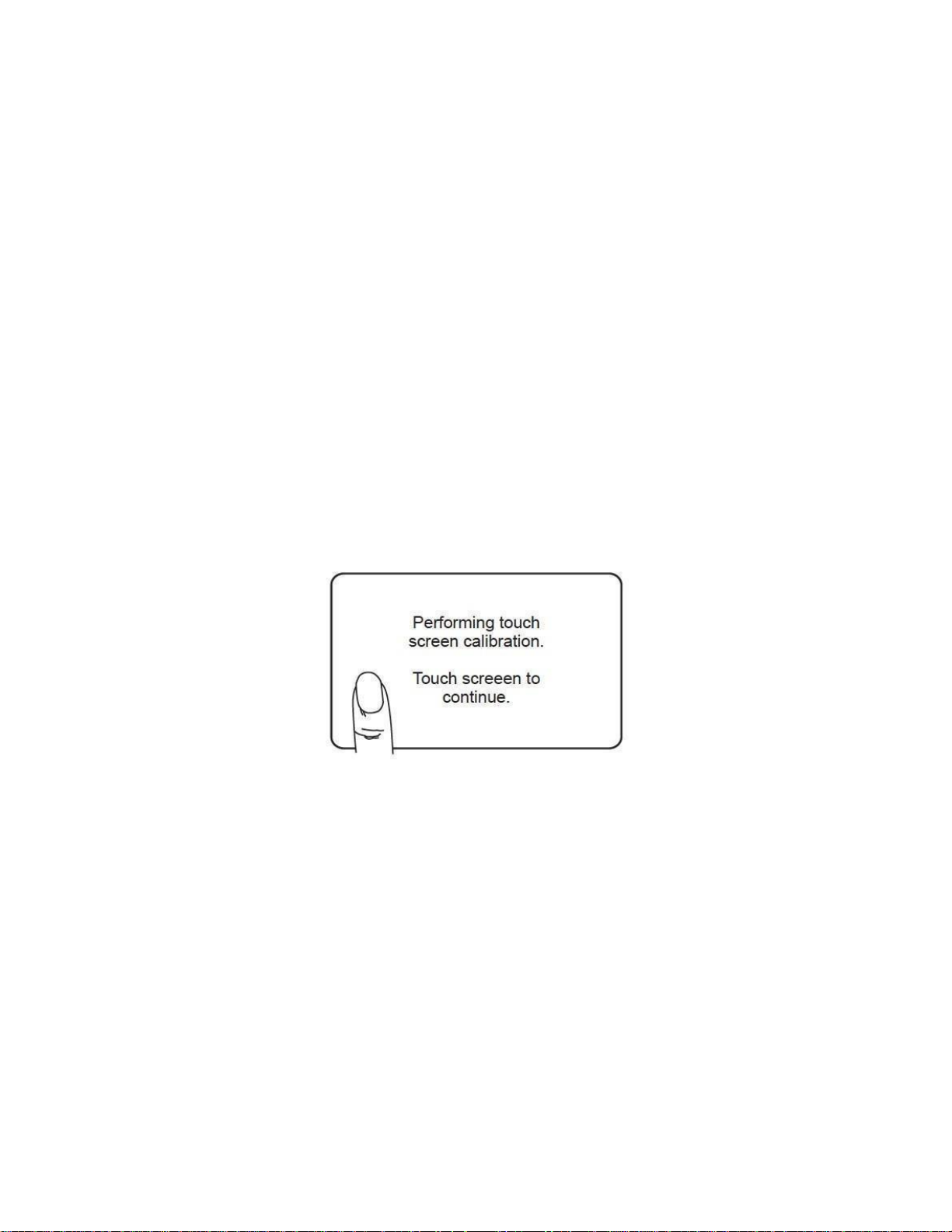
Touchscreen Recalibration
Condition:
During normal operation of the Lavit Dispenser the touchscreen may
become unresponsive or the pushing of icons may result in an incorrect
entry or no response.
Corrective Action:
To reset and to recalibrate the touchscreen perform the following
actions:
1.
Turn the power OFF.
2.
While pressing a finger on the touchscreen, turn the power
ON keeping your finger on the touchscreen.
3.
A white calibration screen will appear.
4.
Follow the instructions on the screen.
5.
After the screen has been recalibrated and starts to restart, turn
the power OFF and the power ON. This will restart the unit in a
normal condition.
6.
The touchscreen should now perform as normal.
7.
If the touchscreen remains unresponsive,
change the touchscreen.
Page 33
31
18-11-26-REV-A
Water Chilling Screen
Issue:
When water is dispensed or a beverage is created a new dispense cycle cannot be
performed because the Water Chilling Screen is on.
Solution:
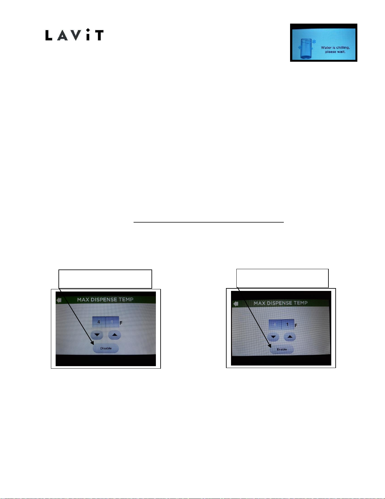
The MAX TEMP function in the service menu has been enabled. Enter the service
menu and select MAX TEMP. IF THE DISABLE icon is present. Press the DISABLE icon
and the ENABLE icon will appear.
Other Comments:
The units come factory set with this feature disabled. A service technician or a
customer who has the password has gained access to the service menu and enabled
the feature. This feature DOES NOT set the water temperature of the unit. It sets
the maximum temperature allowed for water or beverage dispensing. This feature is
set at the factory 41 degrees F.
The incorrect icon
displayed is “Disable”
The
correct
icon displayed is
“Enable”
Page 34

32
18-11-26-REV-A
Issue:
Unit is Not Cooling or Chilling
The unit is powered on for a period of time and the cold water never
chills. In some cases, the water is actually warm or hot.
Solution:
“No Chill” can occur from one of four circumstances:
1.
A defective main PCB
2.
A faulty compressor connection on the
main PCB
3.
A faulty connection at the compressor relay
4.
Loss of Freon or inefficient compressor Causes
1 -3 will result in the compressor not running.
Cause #4 the compressor maybe running but will not cool or chill
the water.
Instructions:
1.
Remove the top of the unit.
2.
With the power on, locate the compressor connection on the
main PCB. This will be the second connector from the top
right on the main PCB.
3.
Verify that the red power light is on adjacent to the connector. If
the light is not on replace the main PCB.
4.
If the light is on disconnect and reconnect the compressor
connector. Determine if the compress or powers on and off
as you do this. Repeat as necessary to determine if the
compressor powers on and off. If the compressor does power
on allow it to run for 20 minutes. Verify that the condenser on
the back of the unit is warm and the water has chilled.
5.
If the condenser is cool then remove the left side panel. Feel
the compressor. If the compressor is running and warm to the
touch and the unit is still not chilling then a loss of Freon has
occurred. Proceed to Step8.
6.
If the compressor is not running and is cool to the touch,
remove the side relay connection on the compressor.
Remove and reinstall the relay connectors (2).
7.
Verify that the compressors running. Allow 20 minute to
determine if the compressor becomes warm to the touch and
the condenser is warm.
8.
If the compressor is running and not chilling issue
continues, Contact Lavit Tech-line .855.750.5377.
Page 35
33
Troubleshooting
Potential problems and solutions.
Condition
Possible Solution
Water dripping
continuously
from the
dispense area.
After the dispensing of a sparkling beverage or sparkling
water several drops may occur as the sparkling water in the
water line heats up and expands. This is normal.
Continuously dripping water is caused by foreign material
lodged in the soda water solenoid. Remove the soda water
solenoid per the instructions on Page xx and disassemble
the solenoid to remove any trapped material.
Leaking water
from the rear
of the unit.
Possible leak issues:
First – Check the still water drain plug and then check the inlet
water line. If those connections are dry and not the source of
the water leak, remove the top cover of the unit.
Inspect the connections on the top of the water tanks.
Remove the ozone generator to view all connections. Ensure
all fittings are tight and dry. Inspect the area around the top
insulation seam towards the left side panel. If there is wetness
in that area the leak may be from the soda tank seal.
Other possible sources of a leak are the soda pump inlet
fitting, the inlet solenoid, or the cold tank drain connection.
To inspect these areas, remove the back panel per the
instructions of Page17.
Inspect the soda pump inlet fitting for leak at the quick
connect insert. Inspect the connections to the inlet
solenoid. If those connections show no evidence of leaking
and water is captured in the area at the bottom of the coldwater tank, the water drain connection to the tank may be
the cause of the leak. Remove the insulation from around
the water tank drain pipe and inspect.
Other possible sources of leaks are the still water and
recirculation pump connections and the cooling coil
connection running to and from the compressor and
condenser.
Page 36
No Sparkling
Water Dispense,
CO2 gas only.
If the soda pump is not filling the soda tank properly then
CO2 gas will be released at the dispense nozzle when you
select a sparkling beverage or sparkling water.
The following four conditions may exist:
1. The CO2 pressure is too high on the CO2 regulator
and the high pressure stops the soda pump from
refilling the tank. Check that the regulator setting is
3.5 bar. Purge CO2 from the rear of the unit.
2. Faulty soda pump. To verify that the soda pump is
powered on inspect the main PCB. The red plug
connection marked PUMP feeds 24V DC to the soda
pump. If the red LED adjacent to the PUMP
connection is on and the soda pump is not running
then it indicates that the pump is faulty and you
should change it.
3. An airlock exists in the water line. If the water line to
the soda pump has an air lock then the pump will run
but not fill the soda tank. To clear an airlock, you will
need to power down the machine and disconnect the
outlet pipe from the soda pump to the soda tank.
Turn the machine back on and run the pump to waste
until the soda pump discharges without air. Power
down, reconnect the water pipe to the soda tank,
power up and verify proper operation.
4. A short circuit exists in the level control line. A short
between the level probe wires will signal the PCB that
the soda tank is full of water. The PCB turns on the
soda pump when the signal lines are open circuit. To
diagnose this fault, unplug the soda tank level control
plug from the PCB (yellow plug marked probe). The
soda pump should run in this condition. Verify the red
LED adjacent to the PUMP connection is on. Replace
the yellow probe plug and the pump will stop.
Dispense sparkling water. The soda pump should
power on and the red LED should be on. If it is not on
then there is a short on the signal lines, normally on
the cap of the cold tank which can be caused by
condensation or a leak. Remove the cold tank
insulation cap and dry any condensation.
Page 37
35
34
Dry powder
dispenses or a
large amount
of undissolved
powder.
This condition will only be present if the mix stream
dispense volume is too low. A low mix stream volume can
occur under the following circumstances:
1. For a POU installation the inlet water stream pressure
has been reduced. If the inlet water is running
through a filter ensure that the filter is not clogged
with sediment. If a low water pressure exists
recalibrating the mix stream may resolve the
problem.
2. If the installation is running off of a bottled water
supply check the bottle. An empty bottle will result in
a dry capsule dispense.
3. A faulty mix stream solenoid will cause a dry powder
dispense. To check if there is a faulty solenoid, locate
on the main PCB the blue plug marked RINSE. Make a
beverage. The RINSE solenoid and the MASTER
solenoid should come on together and allow water to
into the capsule. Both the RINSE and the MASTER
plugs on the main PCB have a red LED adjacent to
them. If the LEDS light and the solenoid does not
open and allow water into the capsule then change
the RINSE solenoid.
4. If the silicone dispense nozzle has been dislodged a
dry or partial beverage dispense can occur. Ensure
Page 38
36
Large Amount of Water Remains in Capsule After Dispense
Issue:
After dispensing a beverage, a large amount of water remains in the capsule.
Solution:
Two possible conditions will create this situation:
1.
The mix stream is improperly calibrated. The mix stream will run
beyond the proper time and continue to fill the capsule. This is
usually accompanied by a dispersed dispense stream spraying all
over. Recalibrate the mix stream to eliminate this condition.
2.
The capsule is not raised fully to 90 degrees vertical. This is
usually caused by an unclean chamber that prevents the
capsule drive mechanism to stop short of 90 degrees. Clean the
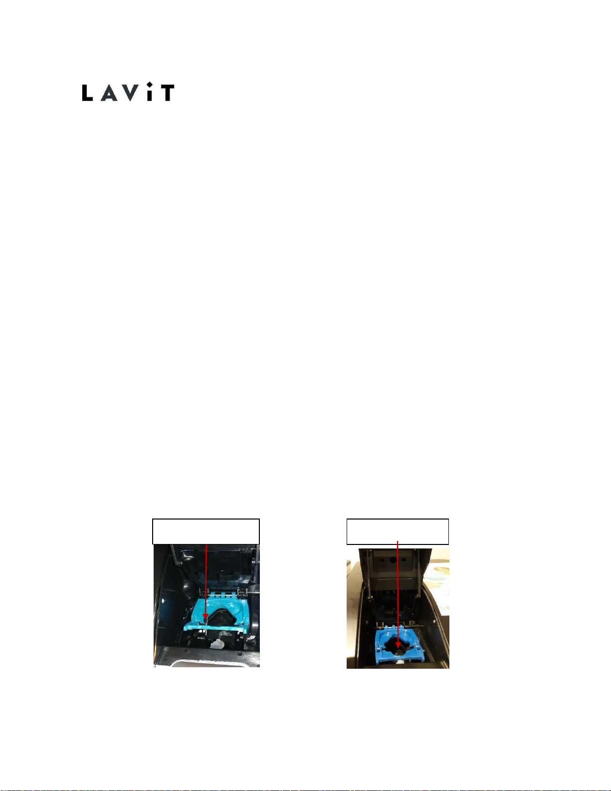
chamber fully. Remove the capsule tray. Pull the linkage attached
to the lid towards you. Reach down underneath the linkage and
grasp the drive mechanism (solid black plastic piece with a semicircle opening). Pull the drive mechanism all the way towards you
until it reaches 90 degrees. Push it all the way back until it stops.
Do this a couple of times. Replace the capsule tray and dispense
a beverage.
A Dirty capsule tray may
stick !
Correct position
Page 39
37
Draining & Decommissioning The Lavit Cooler
1. Turn off the water supply to the m a c h i n e.
2. Using a suitably sized bucket drain the main water tank 1st. (1.5 gallon)
3. Remove the rear bung and drain water to the bucket until the flow stops, tip cooler
Back to ensure all water is drained.
4. If the "error" screen appears then reset it by powering the machine off and on.
5. Drain the soda water only after the main tank has been drained. This is done by
accessing the soda purge program in the service screen.
6. Drain the soda until it blows CO2 gas o n l y .
7. Turn off the power.
8. Turn off the CO2 and remove the CO2 bottle.
9. Secure the CO2 regulator.
10. Purge CO2 gas from the purge valve on the rear of the machine.
11. Replace the still water drain bung and secure with the # 2 Stainless Steel Screw.
12. Remove the power cord
13. Secure the drip tray, power cord, and CO2 regulator in the polystyrene with the
dispenser.
14. Pack the machine in a protective bag and or original packing.
15. Failure to protect the machine during transport can lead to panel damage
NOTE:
➢ ALWAYS! Transport the machine in an upright p o s i ti o n .
Page 40
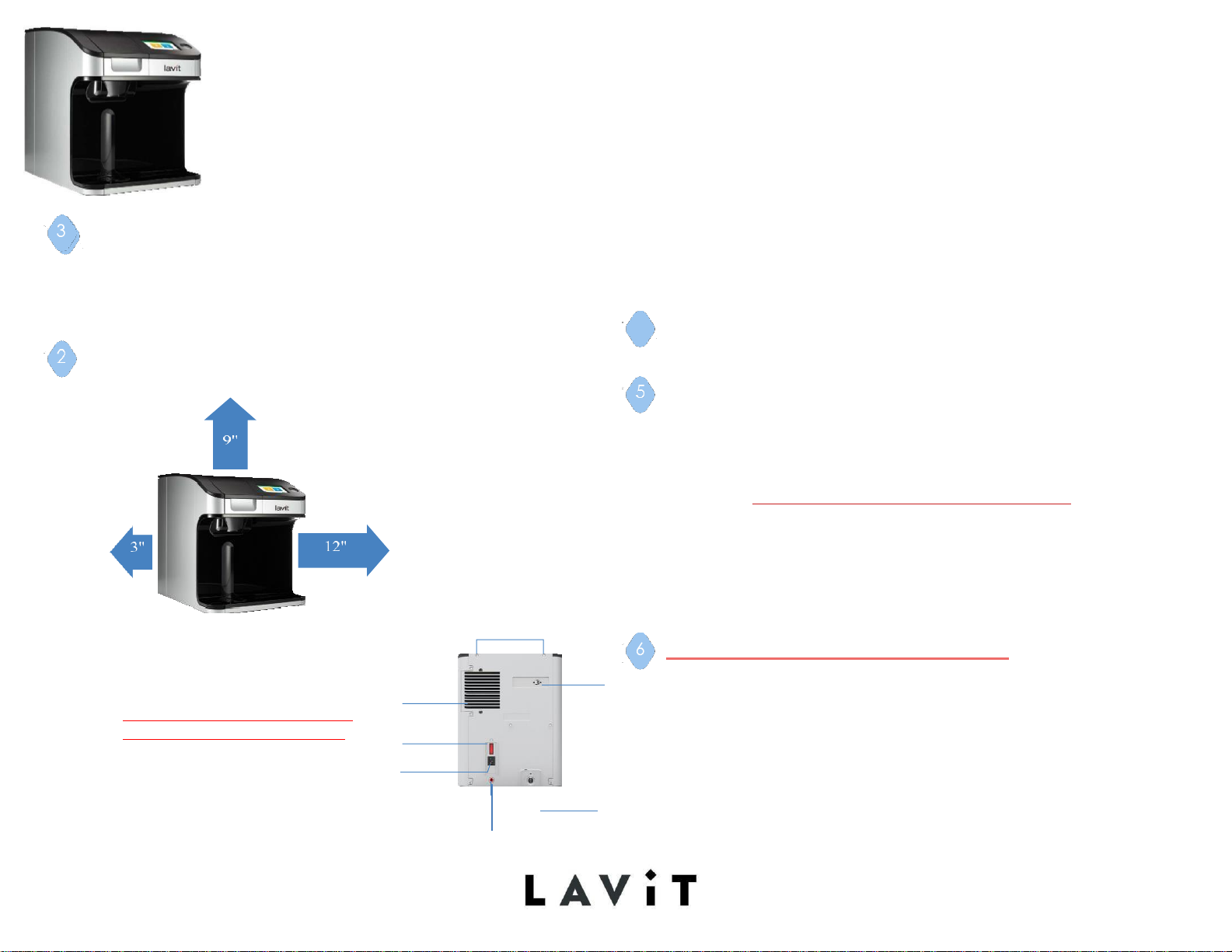
THE LAVIT WATER COOLER
TM
Installation Quick Guide
UNPACK AND INSPECT THE COOLER ON THE OUTSIDE OF
THE STYROFOAM PACKAGING, YOU WILL FIND:
CO2 Regulator
Power Cord
✔ 40 to 60 psi pressure reducing valve
✔¼” quick connect check valve (check local plumbing codes)
✔ ¼” NSF approved water tubing
✔ ¼” shut off valve
✔ NSF 42 and 53 rated carbon filter
✔
#2 Phillips head screwdriver
✔
Measuring cup
It is the responsibility of the installer to follow local
codes during installation
Drip Tray
PLACE THE COOLER AWAY FROM DIRECT SUNLIGHT
AND HEAT. ALLOW ENOUGH SPACE FOR VENTILATION.
INSTALL YOUR FILTER
START UP AND FILL TANK
AND PLUG IN
1. Turn off the main water supply
TOPCOVER SCREWS
CO2
PURGE
VALVE
1.
Power on to unit
2.
System will self-check with software version
3.
NoCO2DetectedScreen willappear thenHOMEScreen will
display.DO NOT INSTALL CO2 AT THIS POINT
4.
Press RED flashing Lavit button to fill water tanks
5.
As the still water tank fills, the WATERFILLING screen will be
displayed.
6.
When the HOME screen appears, the compressor,
recirculationpump,andsodapumpwillstart.
7.
Once Water Droplet Iconturns
black
– move to next step.
NOW YOU MAY INSTALL THE CO2 TANK
2. Tap into your mains water supply
3.
Install your pressure reducing
valve MAX- 60PSI MIN-45PSI
4.
Connect ¼” watersupply line to
inlet connection
CONDENSER
FAN
POWER
SWITCH
COLD
TANK
POWER Cord
Connection
1. Make sure Regulator is in OFF position
2. Before turning on your CO2 tank, purge all CO2 from system
using the purge valve on the left rear of the cooler
3. Screw Regulator on to CO2 cylinder tightly
4. Connect Regulator and attached to CO2 inlet line
located inside the right-side door.
DRAIN
5.
Connect thePowerCord
1/4"QUICKCONNECTWATERINLET
BEHIND
ABOVE
ALL SIDES
4
Page 41
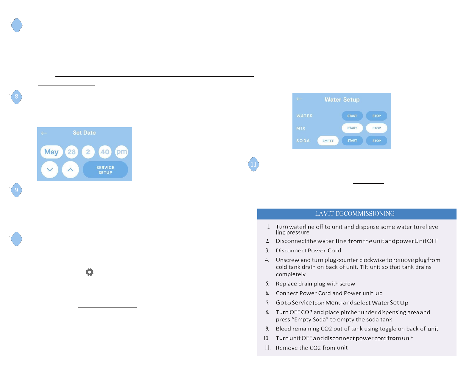
SET CO2 PRESSURE
1. Set the CO2 regulator to 50 psi or (3.5 Bar)
2. Align the arrow to the beginning of the wide RED bar on the knob
3. OnceCO2is turned on, CO2CylinderIcon willchange from redtoblack
4. Purge air from the system from the rear purge valve. (3) one second pulses
NOTE: ITTAKESAPPROXIMATELYTWO HOURS FOR THE SYSTEMTOCHILL DOWN TO THE
PROPER TEMPRETURE
SET UP DATE AND TIME
1. Select the gear icon from the home screen
2. Set the date and time
3. Hitthe back arrow to returntothemainscreen
BLEED AIR FROM LINES
1. Press the Lavit button to clear the still water line
2. Select Water
Only – Medium Soda Water
to clear the
soda water line
CALIBRATION
Proper Beverage Volume is critical to create great tasting
beverages.
1. Select the Gearicon
2. Select Service Set Up shown above in Set date picture
3.Enter Password 8888 – Enter to display the SERVICE
MENU
4.on next screen Select Water Set Up
CALIBRATION continued
There are three water streams in a Lavit Cooler:
1. Still Water–pumped from cold tank
2. Mix Stream– Using an ECO Cap start mix stream for 2- second then
stop. Dump water from your measuring then start mix stream
calibration again stopping it at 12OZ. The Mix stream uses external
inlet water to create the beverage mixture
3. Soda Water – from soda tank using CO2 pressure
Calibrate the three water streams: Still, Mix and Soda.
1. Using a measuring cup press “Start” to begin flowand
“Stop” to end flow when 12 ounces is dispensed
2. Do this for each stream
3. After calibration, verify 12oz volume by creating a new
Still and Carbonated Beverage
7
10
Page 42
Draining & Decommissioning The Lavit Cooler
1. Turn off the water supply to the m a c hi n e .
2. Using a suitably sized bucket drain the main water tank 1st. (1.5 gallon)
3. Remove the rear bung and drain water to the bucket until the flow stops, tip cooler
Back to ensure all water is drained.
4. If the "error" screen appears then reset it by powering the machine off and on.
5. Drain the soda water only after the main tank has been drained. This is done by
accessing the soda purge program in the service screen.
6. Drain the soda until it blows CO2 gas o n l y .
7. Turn off the power.
8. Turn off the CO2 and remove the CO2 bottle.
9. Secure the CO2 regulator.
10. Purge CO2 gas from the purge valve on the rear of the machine.
11. Replace the still water drain bung and secure with the # 2 Stainless Steel Screw.
12. Remove the power cord
13. Secure the drip tray, power cord, and CO2 regulator in the polystyrene with the
dispenser.
14. Pack the machine in a protective bag and or original packing.
15. Failure to protect the machine during transport can lead to panel damage
NOTE:
ALWAYS! Transport the machine in a upright position.
37
Page 43
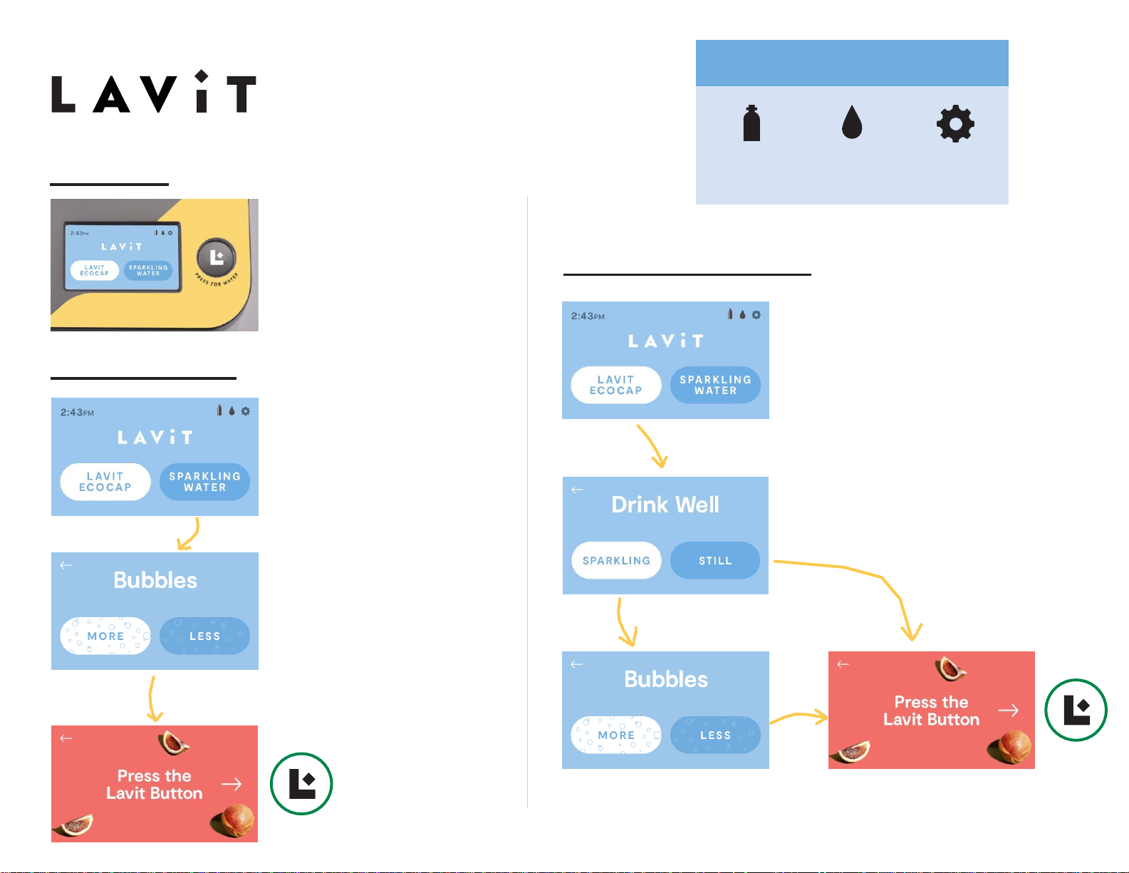
Still Water
User Guide
Sparkling Water
Press and hold the
circle L button to the
right of the screen for
chilled, still water.
Select the “SPARKLING
WATER” button
Choose between MORE
or LESS for your
carbonation level
Using a Lavit EcoCap
Select the “Lavit
EcoCap” button
Choose “SPARKLING” or
“STILL” depending on your
beverage preference
Press the Lavit
button. Press the
Lavit button again
if you wish to stop
the dispense.
If chose SPARKLING, choose
between MORE or LESS for
your carbonation level.
Press the Lavit button. Press
the Lavit button again if you
wish to stop the dispense.
Service Notifications
CO2
Alert
Water
Alert
Service
Setting
 Loading...