

Page 1

V1.00.001
2011-12-07
Page 2

LAUNCH X-431 GDS User’s Manual
All rights reserved! No part of this publication may be reproduced, stored in a
retrieval system or transmitted, in any form or by any means of electronic,
mechanical, photocopying and recording or otherwise, without the prior written
permission of LAUNCH.
This manual is designed only for the use of this unit. LAUNCH is not
respons
ible for any
use of this manual on the other units.
The manual and all the samples herein can be changed without prior notice.
Neither LAUNCH nor its affiliates shall be liable to the purchaser of this unit or
third parties for damages, losses, costs or expenses incurred by purchaser or
third parties as a result of: accident, misuse, or abuse of this unit, or
unauthorized modifications, repairs, or alterations to this unit, or failure to
strictly comply with LAUNCH operating and maintenance instructions.
LAUNCH shall not be liable for any damages or problems arising from the use
of any options or any consumable products other than those designated as
Original LAUNCH Products or LAUNCH Approved Products by LAUNCH.
Notice: other product names used herein are for identification purposes only
and may be trademarks of th
eir respective owners. LAUNCH disclaims any
and all rights in those marks.
This device is only for professional technicians and maintenance personnel.
Registered Trademark
LAUNCH is a registered trademark of LAUNCH TECH. CO., LTD. (LAUNCH)
in China and o
ther countries.
In other countries where any of the LAUNCH
trademarks, service marks, domain names, logos and company names is not
registered, LAUNCH claims other rights associated with unregistered
trademarks, service marks, domain names, logos and company names. Other
products or company names referred to in this manual may be trademarks of
their respective owners. You may not use any trademarks, service marks,
domain names, logos or company name of LAUNCH or any third party without
permission from the owner of the applicable trademarks, service marks,
i
Page 3

LAUNCH X-431 GDS User’s Manual
domain names, logos or company name. You may visit LAUNCH at
http://www.cnlaunch.com
for the information of Launch's NCP and the other
specialized diagnostic tools, or contact Launch by visiting
http://www.X431.com
or writing to Customer Center, LAUNCH TECH. CO.,
LTD., Launch Industrial Park, North of Wuhe Avenue, Banxuegang, Bantian,
Longgang, Shenzhen, Guangdong. P.R. China, to request written permission
to use materials on this manual for purposes or for all other questions relating
to this manual.
ii
Page 4

LAUNCH X-431 GDS User’s Manual
Precautions on Operating Vehicle’s ECU
z Do not disconnect the v
ehicle inner consumer when the ignition switch is
on. High voltage transients may encounter at the moment of
disconnecting, which may damage the sensors and the ECU.
z Protect the computer from magnetic object (such as wireless speaker).
z Do cut off the power supply of ECU system before welding on the
vehicle.
z Pay
more attention to the ECU and the sensors when the operation is
next to them.
z Ground yourse
sensors will be
lf when you disassemble PROM, otherwise ECU and
damaged by static electricity.
z Do not use the pointer ohmmeter instead of DMM to test the ECU and
the sensor without spec
z Do no
t test electric devices in relation with ECU with a test lamp unless
otherwi
se ex
pre
ssly provided.
z Do wear a metal ground strip that one end around your wri
ial requirement.
st and the
other to the vehicle body when you get in and out the vehicle.
z Do connect ECU harness connector fir
mly, otherwise electro elements,
such as IC inside ECU, will be damaged.
Precaution on Operation
z The appl
iance is a sophi
sticated electronic device, never have it clashed
when in use.
z Make sure the appliance is properl
y connected to the DLC to avoid
communication interruptions. During operation, keep the screen upward
and leveled.
z Don’t disconnect the wire ne
twork or Wi-Fi network while software
updating or sending E-mail, otherwise, it will be interrupted.
z After the operation, the stylus shall be inserted into the hole on the back
of the main unit,
and put away the cable and connector, etc accessories
to the box to avoid the lost.
z Handle with care. Avoid collision. Unplug the power after operation.
iii
Page 5
LAUNCH X-431 GDS User’s Manual
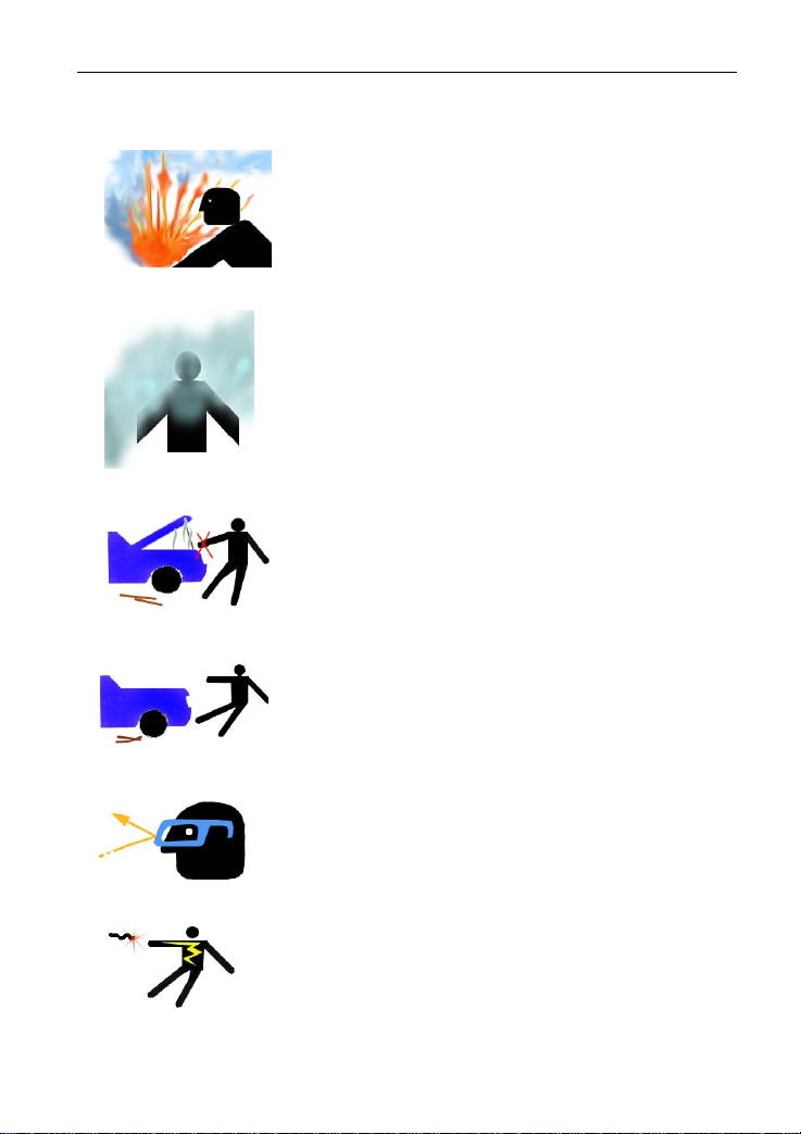
Safety Precautions
z Automotive batteries contain sulfuric acid
that is harmful to skin. In operation, direct
contact with the automotive batteries should
be avoided. Pay attention not to splash the
sulfuric acid into eyes. Keep the ignition
sources away from the battery at all times.
z Engines produce various poisonous
compounds (hydrocarbon, carbon monoxide,
nitrogen oxides, etc,) which should be
avoided. The vehicles shall be tested in a
well-ventilated area.
z Avoid contacting high temperature assembly
such as water tank and vent-pipe as the
temperature of the running engine is very
high.
z Before starting engine, put the speed lever
in the neutral position or in the P position to
avoid injury.
z Wear an ANSI-approved eye shield when
testing or repairing vehicles.
z If you use the battery as a power source,
connect the RED (+) battery clip to the
positive of the vehicle battery and the
BLACK (-) battery clip to the negative.
iv
Page 6

LAUNCH X-431 GDS User’s Manual
Contents
1. FOREWORD............................................................................................. 1
1.1 PRODUCT SUMMARY...............................................................................1
1.2 PRODUCT FEATURES...............................................................................1
1.3 PRODUCT FUNCTIONS .............................................................................1
1.4 TECHNICAL SPECIFICATIONS .....................................................................2
2. ABOUT X-431GDS....................................................................................3
2.1 X-431 GDS MAIN SET ............................................................................ 3
2.1.1 Composition.................................................................................3
2.1.2 Structure......................................................................................4
2.2 X-431 GDS COMMON ACCESSORIES .........................................................8
2.3 First operation.................................................................................9
2.3.1 Turn on........................................................................................ 9
2.3.2 Icons and function items ................................................................ 9
2.3.3 System Settings.......................................................................... 10
3. HOW TO DIAGNOSE...............................................................................27
3.1 PREPARA TION AND CONNECTIONS...........................................................27
3.1.1 Preparation................................................................................. 27
3.1.2 X-431 GDS connections ..............................................................27
3.2 START DIAGNOSING .............................................................................. 27
3.2.1 How to start diagnostic program ................................................... 27
3.3 HOW TO DIAGNOSE............................................................................... 32
3.3.1 Read trouble code.......................................................................33
3.3.2 Clear trouble code.......................................................................34
3.3.3 Read data stream........................................................................35
3.3.4 Special Function ......................................................................... 38
3.3.5 Driving record management.........................................................40
3.4 FLOW CHART FOR ENTERING DIAGNOSTIC PROGRAM ................................... 43
4. HEAVY-DUTY DIAGNOSIS PLATFORM....................................................44
5. BROWSER.............................................................................................45
6. INFORMATION........................................................................................47
6.1 NEWS ................................................................................................47
v
Page 7

LAUNCH X-431 GDS User’s Manual
6.2 SOFTWARE DOWNLOAD INFORMATION....................................................... 49
7. MAILBOX...............................................................................................51
7.1 READ MAIL.......................................................................................... 51
7.2 NEW MAIL...........................................................................................52
8. UPDATE.................................................................................................54
8.1 REGISTER........................................................................................... 54
8.2 UPDATE..............................................................................................56
9. OPTIONAL FUNCTIONS BRIEF FOR X-431 GDS......................................60
9.1 OSCILLOSCOPE....................................................................................60
9.2 IGNITION............................................................................................. 61
9.3 SENSOR............................................................................................. 61
9.4 MULTIMETER....................................................................................... 62
9.5 BATTERYTEST .....................................................................................62
10. FQA......................................................................................................63
vi
Page 8

LAUNCH X-431 GDS User’s Manual
1. Foreword
1.1 Product summary
X-431 GDS is a sophisticated and integrated diagnostic product with powerful
functions developed by LAUNCH. It features wired network, meanwhile it also
supports Wi-Fi communication, which enables you to access Internet, update
online, search information anytime and anywhere, and makes X-431 GDS
diagnose vehicle trouble more conveniently. It has functions of diagnose,
oscilloscope, ignition, sensor, Multimeter, browser and battery test and service
functions such as wireless LAN. VGA extending display function is available.
As a result, it has strong practicability and high performance-price ratio, which
is a helpful assistant for vehicle diagnosis and maintenance.
X-431 GDS is also applicable to HeavyDuty vehicles, depending on whether
HeavyDuty diagnosis software is supplied for your product or not.
1.2 Product features
z High performance industrial control computer runs rapidly and stably.
z Wi-Fi communication makes software upd
convenient.
z Inheriting advanced diagnostic functions from X-431 super scanner, it
almost can diagnose all
makes, and testing speed is greatly improved.
z Perfect service informa
etc.
vehicles from China, Asia, Europe and America
tion, including service documents, service cases
ate and compliant much
1.3 Product functions
Diagnosing: covers a wide range of electrical control systems for any
model from Asia, Europe and America makes; Diagnosing and software
upgrading keep pace with other products.
Wi-Fi connection: easy to
documents and cases online.
Browser: users can visit the service websites saved in Favorites.
(Inputting websi
VGA interface available for external display;
te address manually is disabled temporarily)
make online update, feedback, search service
1
Page 9

LAUNCH X-431 GDS User’s Manual
Ethernet interface for connecting wired network;
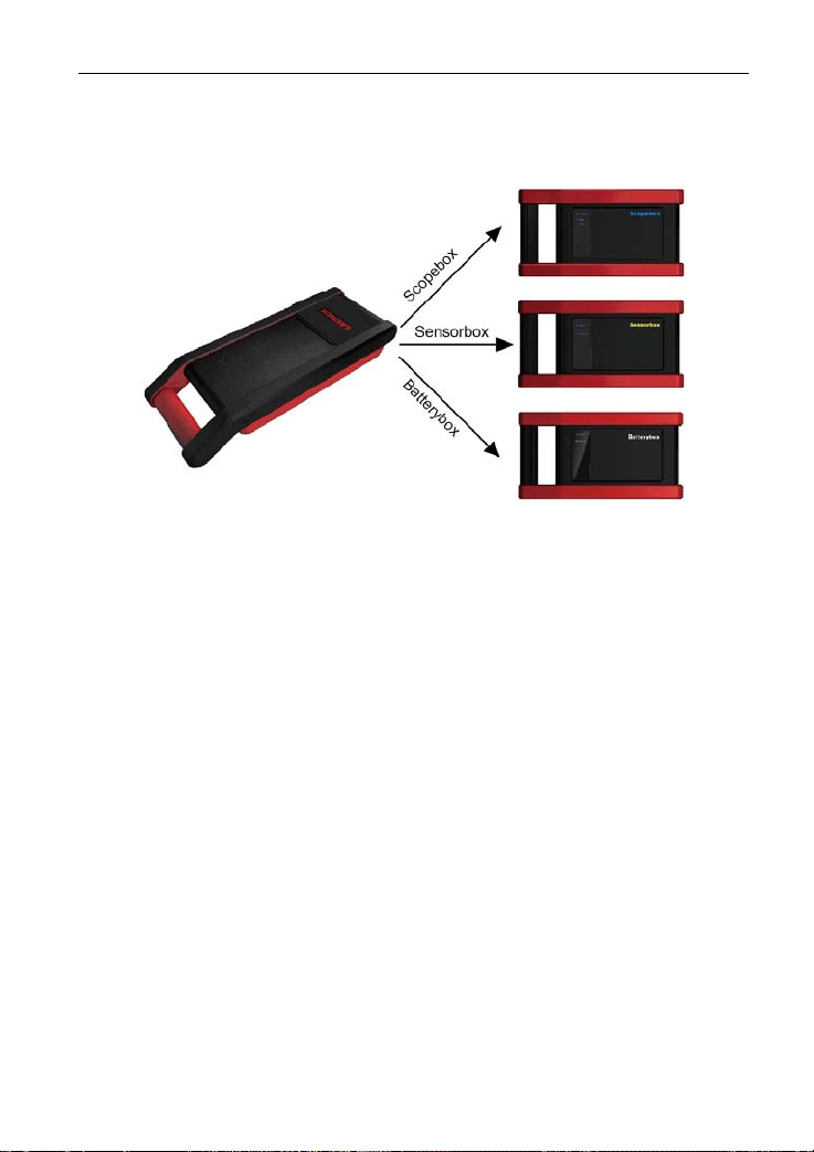
Extending functions by connecting it to Scopebox, Sensorbox and
Batterybox.
1.4 Technical specifications
Operation system: Windows Embedded Standard
CPU: 32bits CPU
Display: 7" TFT Hi-brightness color touch screen
Main unit power supply: DC14V
Working temperature:
Vehicle Type: 12V/24V
Built-in hard disk: 8G
-10℃~55℃
2
Page 10
LAUNCH X-431 GDS User’s Manual
2. About X-431GDS
2.1 X-431 GDS Main set
Figure 2-1 X-431 GDS Diagram
2.1.1 Composition
z Main Unit
Including display, diagnosing, printing and all standard functions of
handheld computer; ba
capacity hard disk to memorize data; supports Wi-Fi communication.
z Scopebox (Optional)
Special Scope
supplied.
z Senso
z Batte
rbox (O
V
ehicle senso
rybox (Optional)
Detects the ve
outside-the-vehicle testi
box and ignition analysis functions for vehicles are
ptional)
r analog
hicle battery status and provides inside-the-vehicle and
sed on Windows operating system; built-in large
test and multimeter test are supported.
ng modes.
3
Page 11

LAUNCH X-431 GDS User’s Manual
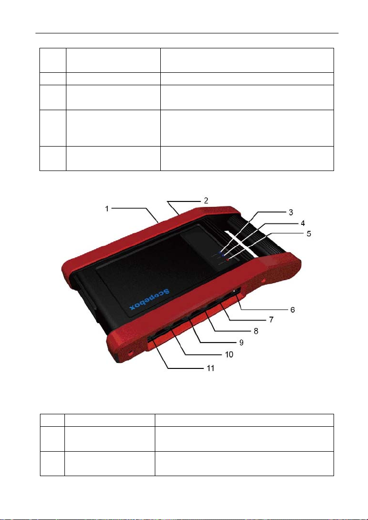
2.1.2 Structure
1. Structure view
Figure 2-2 X-431 GDS Main set structure view
Table 2-1: X-431 GDS terminals and indicators description
No. Name Descriptions
1 Handle Holding or carrying the main unit.
2 SIM slot Not applied for X-431 GDS.
3 Exhaust vent For expelling heating to ensure normal
temperature of internal parts.
4 VGA terminal Connect to projector or display.
5 LAN terminal Connect to wire network with LAN cable.
6 Diagnose terminal Connect to test cable.
7 USB ports Connect to USB devices. While
connecting function boxes, Scopebox
must be connected to the blue USB port.
8 Hard Disk indicator
Indicates diagnosis communication state.
(green)
9 Power indicator (red) Indicates power status.
10 Power connector Connect to outer power to supply power or
charge for main unit.
4
Page 12
LAUNCH X-431 GDS User’s Manual
11 Diagnostic box Communication module between main unit
and vehicle.
12 Printer Print the displayed results.
13 Power switch Press to turn on the device and hold
pressing to turn off the device.
14 Main display Color touch screen to display the function
interface, touch input or manual input is
supported.
15 Air intake vent Intake air to ensure internal parts
temperature normal.
2. Scopebox structure
Figure 2-3 Scopebox structure view
Table 2-2: Scopebox terminals and indicators description
No. Name Descriptions
1 B type USB port Connect to main unit with USB cable when
it is applied as separated USB device.
2 Power connector Connect to power supply via the power
adaptor.
5
Page 13
LAUNCH X-431 GDS User’s Manual
3 Communication
Blinks green during data communication
indicator
4 Operation indicator
Keeps lighting after oscilloscope operated.
(green)
5 Power indicator
Keeps lighting after scopebox powered on.
(red)
6 1K calibration signal
terminals (2 pcs)
One terminal: 1K square wave signal
output, 2VP-PVP-P.
The other terminal: connect to the ground.
7 CH1 Channel 1
8 CH2 Channel 2
9 CH3 Channel 3
10 CH4 Channel 4
11 External trigger External trigger signal
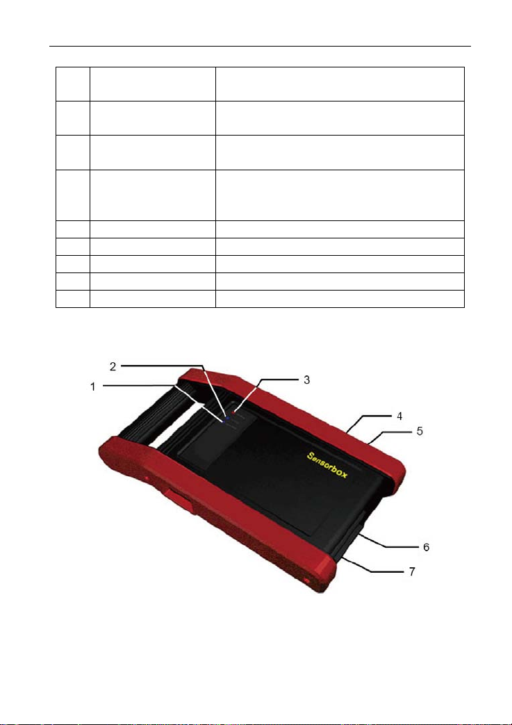
3. Sensorbox structure
Figure 2-4 Sensorbox structure view
6
Page 14
LAUNCH X-431 GDS User’s Manual
Table 2-3: Sensorbox terminals and indicators description
No. Name Description
1 Data receiving
indicator
2 Data sending
Indicator (green) for receiving data from main
unit.
Indicator (green) for sending data to main unit.
indicator
3 Power indicator It keeps steady on (red) after Sensorbox is
powered on.
4 B type USB port Connect to main unit with USB cable when it is
applied as separated USB device.
5 Power connector Connect to power supply through the power
adaptor.
6 COM Common terminal of multimeter
7 VΩHz Testing terminal of multimeter
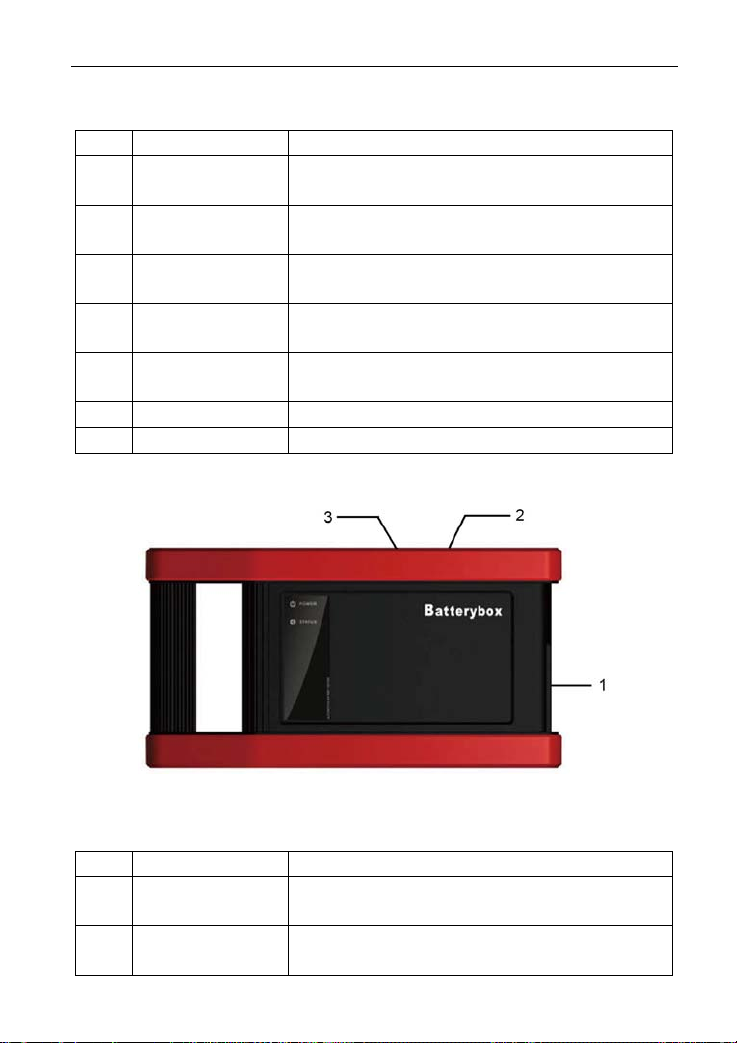
4. Batterybox structure
Figure 2-5 Batterybox structure view
Table 2-4: Batterybox terminals and indicators description
No. Name Description
1 Battery
Connect to battery via cable for testing battery
connector
2 Power connector Connect to power supply via the power
adaptor. (unused)
7
Page 15
LAUNCH X-431 GDS User’s Manual
3 B type USB port Connect to main unit with USB cable when it is
applied as separated USB device.
2.2 X-431 GDS Common accessories
Common accessories for each X-431 GDS are same, but for different
destinations, the accessories of X-431 GDS (such as diagnostic software,
testing connectors) may vary. Please consult from the local agency or check
the package list supplied with X-431 GDS together.
Table 2-5: X-431 GDS common accessories and descriptions
No. Name Descriptions View
1 Main test cable Connect X-431 GDS
to vehicle’s DLC.
2 Diagnostic connector Connect to vehicle’s
DLC. Several
different testing
connectors are
included for each
X-431 GDS.
3 Cigarette lighter
power cable
4 Power adaptor
Obtain power supply
from vehicle’s
e lighter.
cigarett
Convert 100~240V AC
power supply to 14V
DC po
wer supply.
5 Stylus For clicking or writing
on the screen.
6 Accessories Including User’s
Manual, Service
Manual etc.
8
Page 16
LAUNCH X-431 GDS User’s Manual
2.3 First operation
2.3.1 Turn on
Press the [Power Switch] butt
on the main u
nit, the system will
on
begin to initialize, as shown in
Figure 2-6.
Figure 2-6
Note: Hold and press the [Power Switch] button for 6~8 seconds to turn off
the main unit, but this i
s not recommended, please click [Exit system]
icon on the main menu to turn off the device.
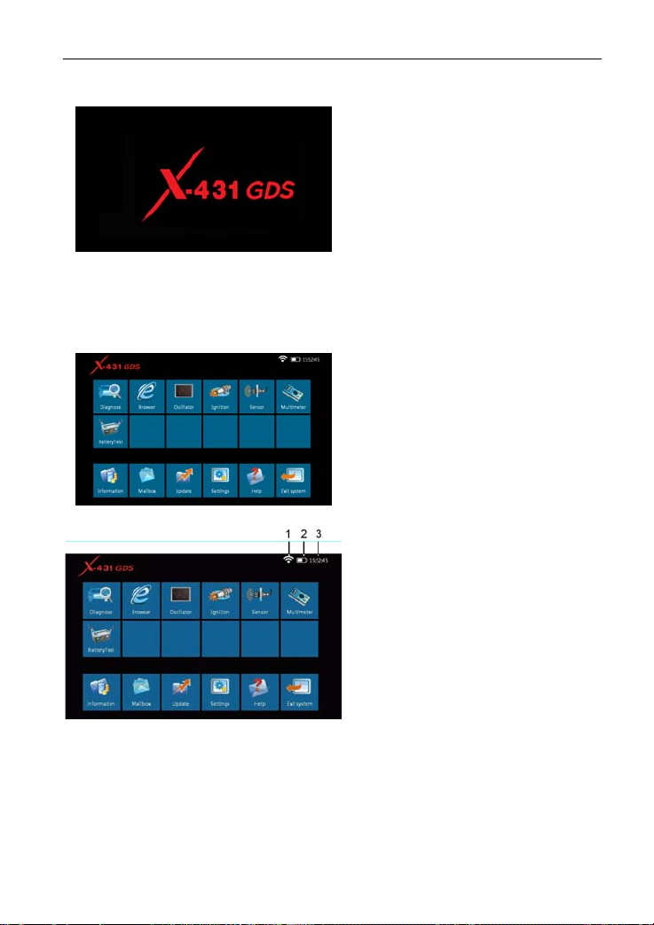
After the system completes
initializing, the main menu
shown
as Figure 2-7 will appear on the
screen. Here you can select a
certain function and operate it.
Figure 2-7
2.3.2 Icons and function items
There are three icons on the top
right corner of main menu, as
shown in Figure 2-8.
Figure 2-8
Signal indicator: Indicate① s
current signal
and its strength.
② Power indicator: Indicates the power capacity / power charging status /
connection to o
uter power supply.
③ Time: Display current local time.
9
Page 17

LAUNCH X-431 GDS User’s Manual
Various function items are listed in the main menu of X-431 GDS: Diagnose,
Browser, Oscilloscope, Ignition, Sensor, Multimeter, BatteryTest, Information,
Mailbox, Update, Settings, Help and Exit system, as shown in Figure 2-8.
Function items and descriptions:
[Diagnose]: Ju
dge vehicle tec
hnical state, find out trouble location and cause.
[Browser]: Visit the service documents websites saved in Favorites. (Manually
inputting a website add
ress is temporarily unavailable.)
[Oscilloscope]: Rapidly determine vehicle electrical equipment and circuit
trouble, making the measurement and setting of vehicle electrical equipment
much easier and
[Ignition]: Display and analyze ignitio
intuitive.
n waveforms, assist to detect current
status and relevant performance of the engine.
[Sensor]: Diagnose/simulate v
[Multimeter]: Measure the physical
ehicle ECU sensor trouble.
parameters such as voltage, resistance,
frequency etc.
[BatteryTest]: The most advanced conduct
ance testing technology in the
world is applied to make vehicle battery and charging system testing safe,
rapid and easy.
[Information]: Obtain the relevant i
nformation of news and software updating
via X-431 website.
[Mailbox]: Feed back the trouble of the device or vehicle to us by E-mail and
we will give you a profe
ssional reply in time.
[Update]: Visit X-431 website by Internet, one-key to update vehicle software,
it is necessary to complete registering before the first operation.
[Settings]: Set the relevant fun
ction operations.
[Help]: Display the relevant help information for users.
[Exit system]: Shut down or restart the mai
n unit.
2.3.3 System Settings
X-431 GDS provides the following setting items: Change Language, Wi-Fi
Settings, User Data Import/Export, Date/T
ime Settings, Power Option, Adjust
10
Page 18
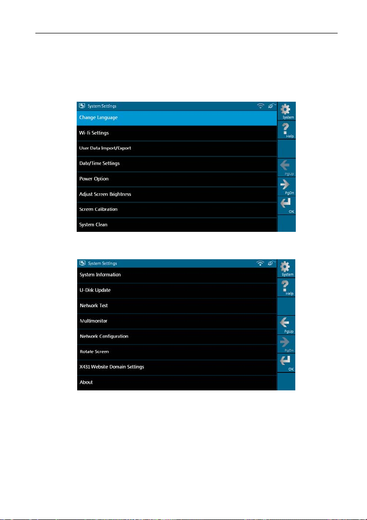
LAUNCH X-431 GDS User’s Manual
Screen Brightness, Screen Calibration, System Clean, System Information,
U-Disk Update, Network Test, Multimonitor, Network Configuration, Rotate
Screen, and X431 Website Domain Settings and About, as shown in Figure
2-9 and Figure 2-10.
Figure 2-9 (Page 1)
Figure 2-10 (Page 2)
11
Page 19
LAUNCH X-431 GDS User’s Manual
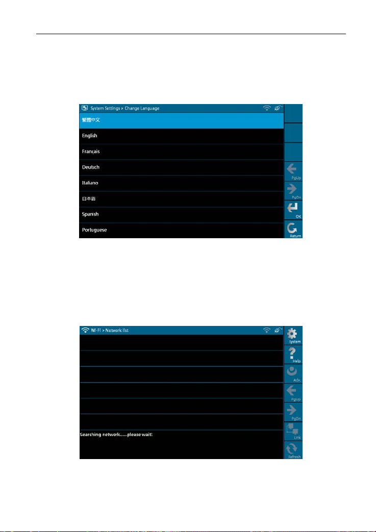
1. Change Language
This option is used to define the system language. Total seven languages are
available: Traditional
Chinese, English, French, German, Italian, Japanese,
Spanish and Portuguese, as shown in Figure 2-11.
Figure 2-11
2. Wi-Fi Settings
This option allows you to configure Wi-Fi network.
Select [Wi-Fi Settings] in [Syst
em Settings] and click [OK], the system starts
searching network, as shown in Figure 2-12.
Figure 2-12
It will take some time to search network, after searching, the searched
12
Page 20
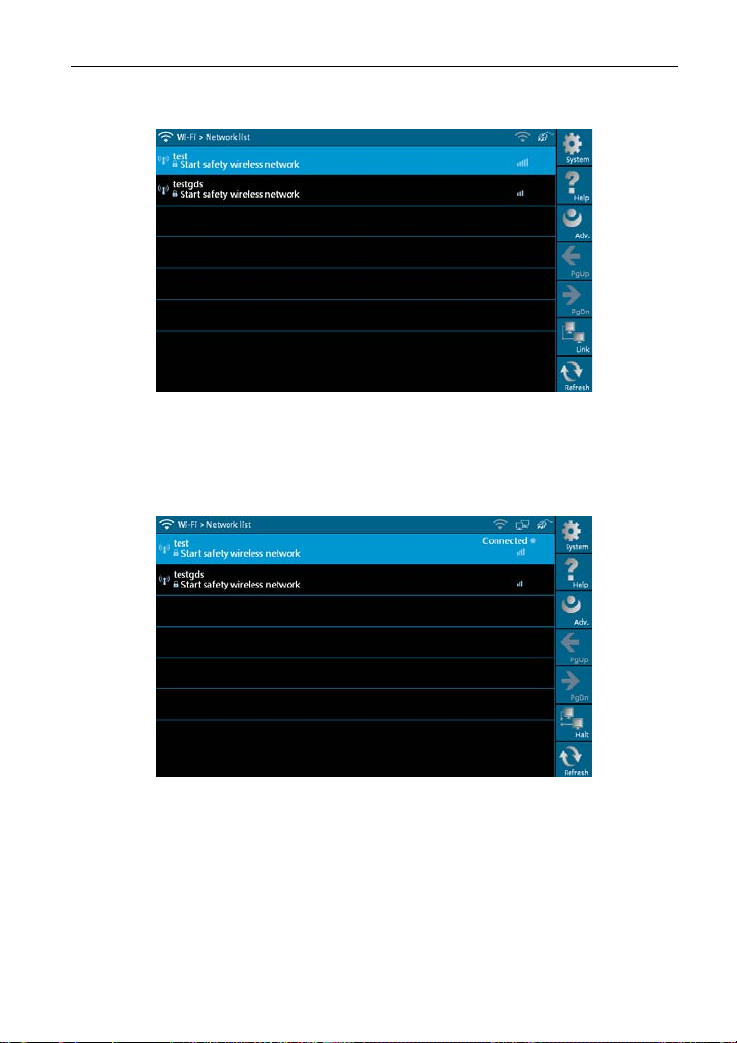
LAUNCH X-431 GDS User’s Manual
networks will be listed on the screen, as shown in Figure 2-13.
Figure 2-13
Select one of the network list and click [Link] in Figure 2-13, “Connected” will
appear on the screen as shown in Figure 2-14, indicating the device is
connected to the network successfully.
Figure 2-14
Note: When selecting Wi-Fi to access Internet, please set Wi-Fi properly and
make sure it is connect
ed successfully, otherwise, the following functions
may be abnormal: Browser, Register, U-Disk Update, Network Test,
Information, Mailbox and Update.
13
Page 21
LAUNCH X-431 GDS User’s Manual
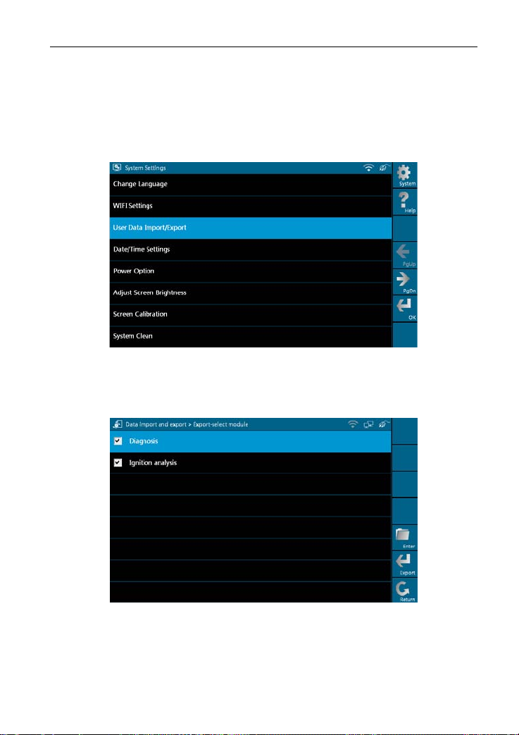
3. User Data Import/Export
This option enables you to import the saved trouble and diagnostic information
from or export it to anoth
Select [
User Data Import/Export] in [Syste
er X-431 GDS for analysis and comparison.
m Settings], a screen shown as
Figure 2-15 will appear.
Figure 2-15
Click [OK] in Figure 2-15, modules will appear on screen for your selection, as
shown in Figure 2-16.
Figure 2-16
In Figure 2-16, select "Diagnosis" and click [Enter], history files similar to
Figure 2-17 will be listed on
the screen.
14
Page 22
LAUNCH X-431 GDS User’s Manual
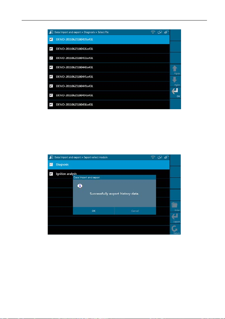
Figure 2-17
Click the checkbox to select the desired files in Figure 2-17 and click [OK] to
export the data.
screen after data is exported successfully. Click
A dialog box shown as in Figure 2-18 will pop up on the
[OK], the [Enter] icon will
become active, and click it to import the history data.
Figure 2-18
Note: If "Export history data fail
ed" appears on screen, please click [Export] to
export the data again.
Method for "Import" is same as "Export". Select the history data and click
rt] to import data.
[Impo
15
Page 23

LAUNCH X-431 GDS User’s Manual
4. Date/Time Settings
This option is used to set the current date and time.
Select [Data/Time Settings] in the [System Settings] and click [OK], the
system will enter the following screen, as shown in Figure 2-19.
Figure 2-19
Click the on-screen buttons to set the date and time, and click [OK] to confirm.
5. Power Option
Through it, you can have a general knowledge of current power information.
Select [Power Option] in [System Settings] and click [OK], a screen similar
to Figure 2-20 will appear:
Figure 2-20
16
Page 24

LAUNCH X-431 GDS User’s Manual
6. Adjust Screen Brightness
It is used to adjust the brightness of the screen to your preference.
Select [Adjust Screen Brightness] in [System Settings] and click [OK], a
screen shown as Figure 2-21 will appear.
Figure 2-21
Drag the slider with the stylus to adjust (0 -100), and click [Return] to exit.
7. Screen Calibration
This option lets you calibrate the touch screen.
Select [Screen Calibration] in [System Settings] and click [OK], a screen
r to Figure 2-22 will ap
simila
pear.
Figure 2-22
17
Page 25

LAUNCH X-431 GDS User’s Manual
In Figure 2-22, properly click the cross symbol on the screen, the cross symbol
changes to blue with a hint sound, then one calibration has been finished. After
calibrating all crosses, the system will automatically return to [System Settings]
interface.
8. System Clean
This option enables you to release disk space, delete unnecessary models,
s, recordings, an
version
d also clear snap file and video text which was
recorded by oscilloscope and ignition mode, etc.
It includes "Clear history data", "Clear diagnosis software - Car", "Clear
diagnosis software - Car(Die
HeavyDuty (Tr
uck/Bus/Engineering Vehicle)".
sel Engine)" and "Clear diagnosis software -
Select [System Clean] in [System Settings] and click [OK], the interface will
wn as Figure 2-23.
be sho
Figure 2-23
Click [Diagnostic] to enter Figure 2-24.
18
Page 26

LAUNCH X-431 GDS User’s Manual
Figure 2-24
1. In Figure 2-24, select [Clear history data] and click [Enter] to enter Figure
2-25. Select one item that you want to clear and click [Clear].
Figure 2-25
Click [OK] in the dialog box shown as Figure 2-25, and the item will be
cleared successfully.
19
Page 27

LAUNCH X-431 GDS User’s Manual
Figure 2-26
2. On figure 2-24, select [Clear diagnosis software-Car] and click [Enter].
Select one car model that you want to clear, as shown in Figure 2-27 and click
[Fast Clean].
Figure 2-27
Note: For "Clear diagnosis software-Car (Diesel Engine)" and "Clear diagnosis
software-HeavyDuty (
Truck/Bus/Engineering Vehicle)", the operations are
same as [Clear diagnosis software-Car]
9. System Information
This option is used to display the system information.
Select [System Information] in [System Settings] and click [OK], then click
20
Page 28

LAUNCH X-431 GDS User’s Manual
[Update] according to the hints, the latest system information will appear on
the screen, as shown in Figure 2-28.
Figure 2-28
10. U-Disk Update
You can download the necessary software from X431 website in the U disk,
and then
connect it to X-431
GDS to update.
Steps to download software with U disk:
1. Connec
2. Access www.x4
t the U disk to a USB port of PC.
.
31.com
3. Log in the website. (Please register your X-431 GDS before operating it
to obtain the Us
er Name and Password)
4. Enter the Download Center.
5. Download the n
ecessary software and save it in the U disk.
Note: Before a
or Wi-Fi co
ccessing X-431 website, please check the network configuration
nnec
tion.
Select [U-
as Figu
Disk Update] in [System Settings] and click [OK], a screen shown
re 2-29 will ap
pear.
21
Page 29

LAUNCH X-431 GDS User’s Manual
Figure 2-29
Click [Find], the system starts searching the software in the U disk, as shown
in Figure 2-30.
Figure 2-30
Mark a "Check" in the box before the software you want to update in Figure
2-30 a
nd click [
Upgrade], the system begins to update. After updating,
"Installation successful" appears in column "Installation status", as shown in
Figure 2-31.
22
Page 30

LAUNCH X-431 GDS User’s Manual
Figure 2-31
11. Network Test
This option helps you detect the network configuration and whether it can
browse
web page nor
mally.
Select [Network Test] in [System Settings] and click [OK], a test result page
will appear on the s
creen. Figure 2-32 indicates that network is detected
successfully.
Figure 2-32
Note: If network detecting failed, please check the network configuration or
Wi-Fi conne
ction, and detect a
gain.
23
Page 31

LAUNCH X-431 GDS User’s Manual
12. Network Configuration
This option is used to configure wired network options.
Wired Network Configuration interface is shown in Figure 2-33.
Figure 2-33
Operations:
Automatically or manually obtain IP includes:
A. You can select "Automatic DNS server address" or "Use the following DNS
server addre
ss" to obtain IP
address.
B. You need to set DNS to manually input IP address.
Suggestion: I
f there is
no network limited, please keep the setting as default,
that means, Automatic IP address and Automatic DNS server address should
be checked. Thus, if you use DHCP to set IP address, no other settings are
needed.
Note: If you use wired network but not Wi-Fi to access Internet, please
configure network properly,
otherwise, the following functions may be
abnormal: Browser, Register, U-Disk Update, Network Test, Information,
Mailbox and Update.
24
Page 32

LAUNCH X-431 GDS User’s Manual
13. Multimonitor
Select [Multimonitor] in [System Settings] a
nd click [OK] to enter.
Figure 2-34
Note: Please confirm that VGA cable is connected to VGA connector of X-431
GDS,
select [P
rojector Mode] and click [Enter], projecting effect will
appear in a while. You can click [Config] to modify the project resolution.
14. Rotate Screen
Select [Rotate Screen] in [System Set
tings] and click [OK] to enter the
interface, as shown in Figure 2-35. You can choose either "Rotate the screen
to the original position" or "Rotate the screen by 180 degree" to view the
display screen easily.
25
Page 33

LAUNCH X-431 GDS User’s Manual
Figure 2-35
Note: Please calibrate the screen every time you rotate the screen (refer to
. Scre
"2.3.3 > 7
en Calibration" for details)
15. X431 Website Domain Settings
The system provides two Domain names for users’ option.
Select [X4
31 Website Domain Settings] in [S
ystem Settings] and click [OK],
the interface will be shown as Figure 2-36.
Figure 2-36
Note: The default website is Hong Kong SAR.
26
Page 34

LAUNCH X-431 GDS User’s Manual
3. How to diagnose
3.1 Preparation and Connections
3.1.1 Preparation
1. Normal testing conditions
z Turn on the vehicle power supply.
z Vehicle battery voltage range should be 11-14V and working voltage of
X-431 GDS is 12V
z Throttle should be closed at its close position.
z Ignition timing and idle speed s
transmission oil temperature are within normal working range (water
temperature is 90-110℃ and transmission oil temperature is 50-80℃).
2. Select testing connectors
Please
vehicles which are equi
3.1.2 X-431 GDS connections
X-431 GDS connection steps are as follows:
z Connect one terminal of main test cable to diagnostic terminal of X-431
z Connect the ot
select the corresponding connectors while X-431 GDS is testing
GDS.
.
hould be within specified range; water and
pped with universal OBD II 16 PIN diagnostic socket.
her terminal of main test cable to vehicle’s DLC.
3.2 Start diagnosing
X-431 GDS can test a lot of series, models and systems which may
continuously increase day by day. Please refer to the "Update" on the main
menu interface for more details of X-431 GDS and download the latest
diagnostic programs to fully enjoy its powerful diagnostic functions.
3.2.1 How to start diagnostic program
Make sure all connections are properly made (For detailed connection, please
refer to
3.1.2)
, p
n to enter the main menu, and then click "Diagnose":
ower o
27
Page 35

LAUNCH X-431 GDS User’s Manual
1. If only for Mini-car, the interface will display as following figure 3-1.
Figure 3-1
Buttons description:
[System]: To display the desktop, view current version No. and exit the
program.
]: To view help information for current operation.
[Help
[File]: T
o view "Recently used models" and "Historical driving records".
[PgUp.]: To d
[PgD
n]: To dis
isplay the previous page.
pl
ay the next page.
Diesel Engine or Heavy-duty vehicles, in addition to Mini-car, the
here is
2. If t
following six po
ssible interfaces shown as figure 3-1a~f will appear.
Figure 3-1a
28
Page 36

LAUNCH X-431 GDS User’s Manual
Figure 3-1b
Figure 3-1c
Figure 3-1d
29
Page 37

LAUNCH X-431 GDS User’s Manual
Figure 3-1e
Figure 3-1f
Click corresponding option and the interface will enter Figure 3-1.
In Figure 3-1, select "DEMO" and the screen will display the selection menu for
DEMO diag
nosis program v
ersion, as shown in Figure 3-2.
Note: The operations for other models, series and systems are similar to
"DEMO". Please refer to the re
levant operation interface for details. Here
only take the "DEMO" for an example.
30
Page 38

LAUNCH X-431 GDS User’s Manual
Figure 3-2
Buttons descriptions:
[System]: To display the deskt
op functions, view current version No. and exit
the program.
[Help]: To view help information
for current operations.
[File]: To view "Recently used models" and "Historical driving records".
[PgUp.]: To view
[PgDn.]: To view the next pa
the p
reviou
s page.
ge.
[OK]: To go to next step.
[Back]: To go back to the previ
ous interface.
31
Page 39

LAUNCH X-431 GDS User’s Manual
3.3 How to diagnose
In Figure 3-2, click [OK] to proceed to Figure 3-3.
Figure 3-3
Note: Diagnosing different vehicles has the same operation steps (including
the test
model, system, mo
please refer to the page prompts during operation.
Buttons description:
[System]: To display the deskt
the program.
[Help]: To view help information
[File]: To view "Recently used models" and "Historical driving records".
[PgUp.]: To view
the p
reviou
[PgDn.]: To view the next pa
[Reset]: To verifies the SMAR
[Back]: To go back to the previ
Click [Engine] in Figure 3-3 (If there is more than one page of system menu,
click [Next Pg.] to view.), the system message "Communication is initialized…"
will appear on the screen, as shown in Figure 3-4.
del year and the DLC selection options),
op functions, view current version No. and exit
for current operations.
s page.
ge.
TBOX again.
ous interface.
32
Page 40

LAUNCH X-431 GDS User’s Manual
Figure 3-4
Note: The test method is similar for different systems, here take [Eng
an exa
mple.
ine] for
After communicating, the interface will skip to the function menu of [Diag
as show
n in Figure 3-5:
nose],
Figure 3-5
gin
In Figure 3-5, there are four functions of [En
e]: "Read trouble code", "Clear
trouble code", "Read data stream" and "Special function".
3.3.1 Read trouble code
Click [Re
ad trouble code] in Figure 3-5, X-431 GDS starts executing this
33
Page 41

LAUNCH X-431 GDS User’s Manual
function. After testing, results will appear on screen, as shown in Figure 3-6.
Figure 3-6
Buttons description:
[System]: To display the deskt
op, view current version and exit the program.
[File]: To view "Historical driving records" and “Print" current DTCs.
[Search]: To s
earch the corres
ponding details of fault code by Google through
Internet.
[Back]: To go back to the previ
ous interface.
If the tested system has no DTCs, a message will appear on the screen,
indicating that there ar
e no DTCs in the system.
3.3.2 Clear trouble code
Click [Clear trouble code] as shown
will be cleared.
in
Figure 3-7, all existing trouble code
34
Page 42

LAUNCH X-431 GDS User’s Manual
Figure 3-7
If trouble codes are cleared successfully, a prompt message will appear on the
screen, as shown in Figur
are no trouble codes, "No DTCs" will appear on the screen.
e 3-8. If all trouble codes have been cleared, or there
Figure 3-8
3.3.3 Read data stream
Click [Read data stream] as shown in Figure 3-9, you can read the running
parameters.
35
Page 43

LAUNCH X-431 GDS User’s Manual
Figure 3-9
As Figure 3-10 shows, the selected datastream are displayed in blue.
Figure 3-10
Click [OK] in Figure 3-10,
dynamic data of the selected datastream will appear
on screen, as shown in Figure 3-11.
36
Page 44

LAUNCH X-431 GDS User’s Manual
Figure 3-11
To view the dynamic waveform of the selected data stream, click [Advanced]
-> [Plot] in
Figure 3-11, as shown in Figure 3-12.
Figure 3-12
Buttons description:
[Plot]: To display single data stream waveform.
[Record]: To record the d
mic data stream during a certain time. (After
yna
clicking, [Record] becomes [Stop])
[Help]: To view the
help information
of current operation.
Click [Pl
ot] in Figure 3-1
2, the waveform of "O2 sensor" will be displayed on
the screen, as shown in Figure 3-13.
37
Page 45

LAUNCH X-431 GDS User’s Manual
Figure 3-13
In Figure 3-13, click [Plot-2],
[Plot-3], [Plot-4]…etc., four waveforms of
selected data stream displayed in different colors will appear on the screen,
which helps you view easily, as shown in Figure 3-14.
Figure 3-14
3.3.4 Special Function
This function is applied to detect whether the system parameters are normal or
not.
Special function] in function me
Click [
nu, the screen will be shown as Figure
3-15.
38
Page 46

LAUNCH X-431 GDS User’s Manual
Figure 3-15
Note: We just take [1# injector] as an example to show how to set the special
function.
To detect whether [1# injector]
works normally or not, click [1# injector].
Figure 3-16
After detecting, the result will appear on the screen, as shown in Figure 3-17.
39
Page 47

LAUNCH X-431 GDS User’s Manual
Figure 3-17
Note: If [1# injector] works abnormally, the system will fail to indicate that the
part has some trouble.
3.3.5 Driving r
ecord management
View the recorded and saved data streams and waveforms (To "Record", click
[Advanced] - >
Click [File] -> [History]
[Record] button on the running interface of data streams).
b
utton on the "Select maker" menu, as shown on
Figure 3-18.
Figure 3-18
The system switches to Figure 3-19, listing datastream information for different
vehicles and records in
different time.
40
Page 48

LAUNCH X-431 GDS User’s Manual
Figure 3-19
Select the one you want to view and click [Open] in Figure 3-19, recor
ded
datastream will be shown on the screen, similar to Figure 3-20.
Figure 3-20
Select the desired datastream and click [OK], then the rec
datastream information will appear, as shown in Figure 3-21.
41
orded dynamic
Page 49

LAUNCH X-431 GDS User’s Manual
Figure 3-21
42
Page 50

LAUNCH X-431 GDS User’s Manual
3.4 Flow chart for entering diagnostic program
Press Power Switch to turn on
Single click [Diagnose] in the main menu.
"Select maker" interface of X-431 GDS
Select the model per the icon. Here
only take some functions of DEMO for
example as the operations on the other
models, series, and systems are the
same.
Enter diagnose interface
Read
DTCs
Clear
DTCs
Read data
streams
Special
function
43
Page 51

LAUNCH X-431 GDS User’s Manual
4. Heavy-Duty diagnosis platform
Heavy-Duty platform included in X-431 GDS is designed for Heavy-Duty
vehicles including diesel and gasoline automotive diagnosis. Users can select
Heavy-Duty function depending on product configuration.
It has the following features:
z No need to switch voltage level
z Support all the current X-431 test software.
z Fast upgrading
via the interne
models.
z International standard design, applicable to all diagnostic sockets.
z Including all the electronic control system.
z Unique data transmission to ensure update in time.
For more de
y-Duty Au
“Heav
tailed Heavy
tomobile Diagnostic Platform User’s Manual”.
-Duty diagnosing and operations, please refer to
Note: The Heavy-Duty function can be activated if Heavy-Duty product
configuration was purchased.
when testing 24V trucks.
to keep updated with the latest vehicle
t
44
Page 52

LAUNCH X-431 GDS User’s Manual
5. Browser
Browser is available on X-431 GDS, which helps you view and obtain relevant
service docume
Click [Browser] on the
Click [Fav
as shown in Figure 4-2 and Figure 4-3.
nts from the third-party website saved in Favorites.
main menu to enter b
orites] and select [View
Figure 4-1
], the website list will appear on the screen,
rowser, as shown in Figure 4-1.
Figure 4-2
45
Page 53

LAUNCH X-431 GDS User’s Manual
Figure 4-3
Select a desired website shown as Figure 4-4, and click [Open link] to browse
the contents of the website quickly.
Figure 4-4
Notes:
1. Before operating Browser, please make sure that Network Configuration or
Wi-Fi has b
een connected suc
cessfully.
2. Only the website listed in Favorites can be viewed presently, manually
inputting website addre
ss is unavailable now.
46
Page 54

LAUNCH X-431 GDS User’s Manual
6. Information
This option enables you to obtain the latest news and software download
information about the device.
6.1 News
Click [Information] on the main menu, the system starts checking network, as
shown in Figure 6-1.
Figure 6-1
After network accesses successfully, [N
screen, as shown in Figure 6-2.
ews] interfac
e will appear on the
Figure 6-2
47
Page 55

LAUNCH X-431 GDS User’s Manual
Buttons description:
[System]: To display the desktop, view current version or exit the program.
[Help]: T
[Info]: To switc
o view the help information of current operation.
h to "Software downloads Information" interface.
[PgUp]: To view the previous page.
[PgDn]: To view the next page.
[View]:
[Retry]: T
To view the details.
o re-try the current operation.
Select
one
ain news in Figure 6-2 and click [View], det
cert
ailed information will
appear on the screen, as shown in Figure 6-3.
Buttons description:
[PgUp]: To view the previous page.
[PgDn]: To view the next page.
[Return]: T
[NextItem]: T
o return to the previous interface.
o view the next item.
If read timeout,
Figure 6-4. In this case, pleas
a prompt message will appear on the screen, as shown in
e check your network configuration and click
"Retry".
Figure 6-3
48
Page 56

LAUNCH X-431 GDS User’s Manual
Figure 6-4
6.2 Software download information
Click [Info] in Figure 6-2, the system will switch to software download info
interface, as shown in Figure 6-5.
Figure 6-5
Button description:
[System]: To display the desktop, view the version or exit the program.
[Help]: T
[News]: To swit
o view the help information of current operation.
ch to "News" interface.
[PgUp]: To view the previous page.
[PgDn]: To view the next page.
49
Page 57

LAUNCH X-431 GDS User’s Manual
[View]: To view the details.
[Retry]: To retry the same operation.
In Figure 6-5, s
elect one of the software programs and click [View], the
system
will enter the content page, as shown in Figure 6-6.
Figure 6-6
50
Page 58

LAUNCH X-431 GDS User’s Manual
7. Mailbox
X-431 GDS has a Mailbox function, by which you can send E-mail to us once
you come across any question or problem unresolved, and we will give you
professional answer in time.
7.1 Read mail
Click [Mailbox] on the main menu, system starts checking network, as shown
in Figure 7-1.
Figure 7-1
After accessing network, the system will display as Figure 7-2.
Figure 7-2
51
Page 59

LAUNCH X-431 GDS User’s Manual
In Mailbox interface, there are four items: Unread mail, Read mail, Sent mail
and Draft box. Select one (e.g. Read mail), and click [View] to read the details.
Figure 7-3
7.2 New mail
Click [NewMail] in Figure 7-3, mail writing interface appears on the screen, as
shown in Figure 7-4.
Figure 7-4
Write down the title and contents by stylus manually, as shown in Figure 7-5.
52
Page 60

LAUNCH X-431 GDS User’s Manual
Figure 7-5
Buttons description:
[Save]: To save a mail that is not finished or will be sent later.
[Send]: To sen
[Return]: T
d the mail.
o return to the previous interface.
When a new mail is finished, click [Se
nd]. If the mail is sent o
ut successfully, a
dialog box will appear as shown in Figure 7-6.
Figure 7-6
If the mail fails to send out, a prompt message will appear on the screen, as
shown in Figure 7-7.
53
Page 61

LAUNCH X-431 GDS User’s Manual
Figure 7-7
Click [OK] in Figure 7-7 to send the mail again, or click [Cancel] to canc
sending.
Note: Please check the network configuration or Wi-Fi connection before
operating Mailbox functi
on.
el
8. Update
X-431 GDS provides quick and easy software update service, by which you
can enjoy all update services including download and update the software.
Note: Enter the update center, vehicle software which can be updated are
default to check, you
also click [Select] to select all or cancel all.
can click [Update] to perform one-key update. You can
8.1 Register
To operate this device, you have to experience a product registration. After
entering the function modules, a registration page will appear automatically
and once registering is complete, this page will never appear again.
Note: Before registering, please check you network configuration or Wi-Fi
connecti
Click [
on.
Update] on the main menu, terms of update service will be shown on
54
Page 62

LAUNCH X-431 GDS User’s Manual
the screen, as shown in Figure 8-1.
Figure 8-1
Agree
Read the "Terms of Service of X431 Website" and click [
] to proceed to
the next step, as shown in Figure 8-2. Some registration information are
required to fill (by stylus or manually input).
Fill the product information
Figure 8-2
By default, Product SN is created by system. While purchasing this product,
you will be of
fered one envelop, in which there is the register password
(secret). You can obtain the dealer code from the dealer. Complete filling the
information in Figure 8-2 and click [Next step], a new dialogue box pops up,
55
Page 63

LAUNCH X-431 GDS User’s Manual
then fill the detailed user information (items with "*" must be filled, confirm
password must be same as login password, Email must be effective and same
as confirm Email, we will send you the secret information to this Email after
registering successfully.). Click [Register], a prompt message indicating that
you have registered successfully will appear on the screen, and you can enter
purchasing or download center.
Note: Please contact the local dealers if you can not register.
8.2 Update
While updating, the system will check network configuration, perform ID
verification and access latest version information, as shown in Figure 8-3.
Figure 8-3
Software update list appears on the screen, as shown in Figure 8-4.
56
Page 64

LAUNCH X-431 GDS User’s Manual
Figure 8-4
In Figure 8-4,
Current Ver.: current version No.
Update Ver.: the lowest version that can be installed currently.
Top version: the current top version.
Click [His
tory] to select one or several desired software, as shown in Figure
8-5.
Figure 8-5
Button description:
[System]: To display the desktop, view the current version or exit the program.
[Help]: T
[Update]: T
o view the help information of current page operation.
o execute software update operation.
57
Page 65

LAUNCH X-431 GDS User’s Manual
[History]: To select version that can be downloaded or corresponding vehicle.
In Figure 8-5, you can select several pieces of software and update them
together for correspondi
ng vehicles, then click [Update].
Here, we take "BENZ" as an example to explain one-key update.
Select "BENZ" and click [Update] in Figure 8-5, the software will be
aded and installed auto
downlo
matically, as shown in Figure 8-6 and Figure
8-7.
Figure 8-6
Figure 8-6 shows the downloading progress. When "100%" appears, it
indicates that the software ha
s been downloaded completely.
Figure 8-7
58
Page 66

LAUNCH X-431 GDS User’s Manual
Figure 8-7 shows the installation state. If "Installation succeed" appears, it
indicates that installation has completed.
If the network configuration is not correct, software download will fail and
[Retr
y] turns a
ctive. In this case, please check the network and download it
again, as shown in Figure 8-8.
Figure 8-8
Button description:
[System]: To display the desktop, view current version or exit the program.
[Help]: T
[Stop]: To
[Retry]: To exe
[Return]: To return to the previ
o view the help information of current page operation.
stop downloading or installing.
cute the same operation again.
ous interface.
59
Page 67

LAUNCH X-431 GDS User’s Manual
9. Optional functions brief for X-431 GDS
9.1 Oscilloscope
X-431 GDS has an optional function of oscilloscope, which can make the auto
repair technician quickly judged the faults on automotive electronic equipment
and wiring. If using an ordinary oscilloscope to test the electronic equipment,
the biggest problem is how to set the oscilloscope (adjust the display
parameters of oscilloscope to make the waveform become clear), while using
the automotive oscilloscope can make the setting on testing automotive
electronic equipment become simple and intuitive (via automatic setting
function), just via clicking "Automatic settings", the waveform can be directly
observed without any setting and adjustment. For some automotive electronic
equipment, the signal change rate is very fast, whose cycle reached a
thousandth, besides, many fault signals are intermittent, and unsteady, which
makes the ordinary equipments, such as decoder, Multimeter etc., hard to
capture such fault signal and affects the fault diagnosis and trouble; and the
oscilloscope sweep speed is far greater than the signal frequency of such
vehicles, usually 5-10 times of the measured signal. The automotive
oscilloscope not only can quickly capture the circuit signal, but also can slowly
display the waveform to observe and analyze. It can also record and store the
tested signal waveform which can be playback to observe for the fast signal,
having great convenience to failure analysis. Either high-speed signal (e.g.:
injection nozzle, intermittent fault signal) or the slow-speed signal (e.g. the
throttle position change and the oxygen sensor signal) can be observed
through automotive oscilloscope in an appropriate waveform.
We know that the electronic signal can be compared and judged via testing
rame
five pa
maximum voltage of signal), the frequency (the cycle time of signal), the shape
(the appearance of signal), the pulse width (the duty cycle or the time range of
signal), and the array (the repetition characteristic of signal), which can be
tested, displayed, saved by the automotive oscilloscope. Via the waveform
analysis can further detect the circuit fault on sensors, actuators, circuits, and
electronic control units, etc.
For detailed operations and specifications, please refer to X431 GDS
Scopebo
indexe
ters
x user’s manu
s. The five parameters indexes are the amplitude (the
al.
60
Page 68

LAUNCH X-431 GDS User’s Manual
9.2 Ignition
The ignition system is the system which has greatest impact on the
performances of gasoline engine, as the statistical data shows that nearly half
of the failures are caused by poor work of electrical system. And the
performance tests of engine often start from the ignition system. Nowadays
ignition system includes distributor and distributorless. Distributorless includes
independent ignition and simultaneous ignition.
1. Distributor ignition system: conventionally includes contact breaker
(commonly known as the pl
magnet, infrared or hall components breakless ignition system.
2. Direct ignition system: crankshaft sensor send out the ignition timing signal
and cylinder identificati
specified signal in specified time, each cylinder has its independent ignition
coil.
3. Simultaneous ignition system: two cylinders share one ignition coil, when
two cylinder pistons
compression, the other is the exhaust), two spark plugs will be ignited at the
same time, at this time, the ignition for the former cylinder with
high-pressure low temperature gas mixture, the ignition is valid, while for
the latter one with low-pressure high temperature exhaust gas, the ignition
is invalid.
X-431 GDS can test and analyze the primary/secondary signal coming from
various engine ignition s
For detailed operations and specifications, refer to X431 GDS Scopebox
user’s man
ual.
atinum) contact-controlled ignition system and
on signal for the specified cylinder send out the
reach top dead center at the same time (one is
ystems.
9.3 Sensor
Vehicle sensors are the signal input devices for electrical control systems,
which can transform all kinds of running parameters, such as vehicle speed,
coolant temperature, engine RPM, air flow, throttle opening, etc., into the
electronic signal for the vehicle computer who can optimize the engine running
status per the above-mentioned parameters to keep the engine working in a
prime status. As the sensors can be separated into many types, when you
troubleshoot a related-sensor fault, you shall focus not only on the sensor itself,
61
Page 69

LAUNCH X-431 GDS User’s Manual
but also the whole trouble circuit and variety of sensor's parameters while
running. “Sensor simulation test” function is specially developed to diagnose
and simulate vehicle sensor faults, including "DC voltage simulation", "Fixed
frequency simulation", "Predefined waveform simulation", and "Hand-drawing
waveform simulation", which can help customer to diagnose and simulate the
vehicle sensors quickly and conveniently.
For detailed operations and specifications, refer to X431 GDS Sensorbox
user’s manual.
9.4 Multimeter
X-431 GDS provides an optional function of “Multimeter”, by which, you can
perform voltage, resistance or frequency test.
For detailed operations and specifications, refer to X431 GDS Sensorbox
user’s man
ual.
9.5 BatteryTest
X-431 GDS provides an optional function of “BatteryTest”, which adopts the
most advanced conductance testing technology in the world, detects the
vehicle battery status and provides in-vehicle and out-vehicle testing modes.
In-vehicle testing can complete charging system and ignition system testing.
Several battery standards and regulars are supported, including CCA, DIN,
IEC, EN, JIS, SAE and GB etc.
For detailed operations and specification, refer to X431 GDS Batterybox user’s
manual.
62
Page 70

LAUNCH X-431 GDS User’s Manual
10. FQA
X431 GDS is a hi-tech product. With the development of modern automotive
industry, more and more new technologies will be adopted and there may be
questions during operation, including the software, hardware, operation and
something related to the vehicles. Read the user’s manual to get the answer
whenever you have any question, or contact our Customer Service Center for
help. Here, we list some frequently asked questions and answers relating to
the using of X431 GDS.
About Hardware
Q: Why does the LCD touch screen respond so slowly in cold whether?
A: It is because the ambient temperature is close to the lower limit of
operating temperature range (-10-55℃). Under this situation, it is
necessary to warm up the machine for 30 minutes before test.
Q: There is only backlight and no character on the screen. What should
I do?
A: Check if the power is well connected. Turn off the machine, unplug the
power connect
connected to the power for 1 second.
Q: Why there is no response or response incorrectly while clicking the
screen with touch pen?
A: Please c
for details.
About Op
Q: System halts while reading data stream.
A: Connector is loosen, shutdown the device and connect well to test again.
Q: E-mail sending failed.
A: Check netwo
or and re-plug it. Turn on the machine after it has been
alibrate the screen again. Refer to “2.3.3 7. Screen Calibration”
erations
rk configuration.
63
Page 71

LAUNCH X-431 GDS User’s Manual
Q: Fail in Mail operation while feedback problems.
A: Product is not registered, please register and operate again.
Q: Software download fa
A: Check netwo
rk configuration.
iled.
Q:
Blank screen after operating for a period.
A: When there
is no externa
l power supply connected, power of battery
exhausts, Please connect external power supply.
About Vehicles
Q: Main screen blinks at the moment when en
gine ignition.
A: It results from electromagnetic interference and this is normal phenomena.
Q: Detect
ing interrupted while testing.
A: It results from electromagnetic interference or loose connection.
Q: No res
A:
ponse while communicating with vehicle ECU.
Make sure that the voltage of vehicle battery is in specified range, the
throttle is in the
closed position, and all electrical consumers are turned off,
and water temperature is in specified range.
Q: Some systems can not be diagnosed
A: The diagnostic socket for the system on some early vehicle may be
separated. Refer to the
vehicle instruction manual.
Q: No corresponding trouble codes description.
A: It is generally normal circuit “sequel”, search the most approaching trouble
code and analy
ze it.
64
Page 72

LAUNCH X-431 GDS User’s Manual
Warranty
THIS WARRANTY IS EXPRESSLY LIMITED TO PERSONS WHO
PURCHASE LAUNCH PRODUCTS FOR PURPOSES OF RESALE OR USE
IN THE ORDINARY COURSE OF THE BUYER’S BUSINESS .
LAUNCH electronic product is warranted against defects in materials and
manship fo
work
warranty does not cover any part that has been abused, altered, used for a
purpose other than for which it was intended, or used in a manner inconsistent
with instructions regarding use. The exclusive remedy for any automotive
meter found to be defective is repair or replacement, and LAUNCH shall not
be liable for any consequential or incidental damages. Final determination of
defects shall be made by LAUNCH in accordance with procedures established
by LAUNCH. No agent, employee, or representative of LAUNCH has any
authority to bind LAUNCH to any affirmation, representation, or warranty
concerning LAUNCH automotive meters, except as stated herein.
r one year (12 months) from date of delivery to the user. This
Disclaimer
THE ABOVE WARRANTY IS IN LIEU OF ANY OTHER WARRANTY,
EXPRESSED OR IMPLIED, INCLUDING ANY WARRANTY OF
MERCHANTABILITY OR FITNESS FOR A PARTICULAR PURPOSE.
Order Information
Replaceable and optional parts can be ordered directly from your LAUNCH
authorized tool supplier. Your order should include the following information:
1. Quantity
2. Part number
3. Item description
Customer Service Department
If you have any questions on the operation of the unit, please contact us:
+86-0755-84528767
If your unit requires repair service, return it to the manufacturer with a copy of
the sa
les receip
t and a note describing the problem. If the unit is determined to
65
Page 73

LAUNCH X-431 GDS User’s Manual
be in warranty, it will be repaired or replaced at no charge. If the unit is
determined to be out of warranty, it will be repaired for a nominal service
charge plus return freight. Send the unit prepaid to:
Attn: Customer Service Department
LAUNCH TECH. CO., LTD.
Launch Industrial Park, North of Wuhe Avenue, Banxuegang, Bantian,
Longgan
g, Shenzhen, Guangd
ong P.R.China, 518129
Launch website: http://www.cnlaunch.com
66
Page 74

LAUNCH X-431 GDS User’s Manual
X-431 GDS SMARTBOX Serial No.
Dealer code
Notes:
1. The
Launch Tech Co., Ltd. shall label the "SMARTBOX SN" before
delivering;
2. The deale
r sha
ll fill in the "De
aler Code" o
n the box and stamp on it
before selling.
3. The “SMARTBOX SN” and “Dealer Code" need to be on site while
updating online via wired ne
twork or Wi-Fi. See "Update" in this manual
for the details. Please keep this manual well.
4. Dealers shall add the "Dealer Code" and the other information onto the
website: http://www
.x431.com after sold the products, otherwise the
user can't register and upgrade online via wired network or Wi-Fi.
Page 75

LAUNCH X-431 GDS User’s Manual
Statement: LAUNCH reserves the rights to make any change to product
designs and specifications without notice. The actual object may differ a little
from the descriptions in the manual in physical appearance, color and
configuration. We have tried our best to make the descriptions and
illustrations in the manual as accurate as possible, and defects are
inevitable, if you have any question, please contact local dealer or after-sale
service center of LAUNCH, LAUNCH does not bear any responsibility
arisin g from misunderstandings.
 Loading...