


FCC ID: XUJS3001
Heavy duty / Medium duty / Light duty Vehicle Communication Interface
S3001
LAUNCH
Launch Tech Co., Ltd.

LAUNCH |
S3001 User Manual |
Copyright Information
Copyright © 2018 by LAUNCH TECH. CO., LTD. All rights reserved. No part of this publication may be reproduced, stored in a retrieval system, or transmitted in any form or by any means, electronic, mechanical, photocopying, recording or otherwise, without the prior written permission of LAUNCH. The information contained herein is designed only for the use of this unit. LAUNCH is not responsible for any use of this information as applied to other units.
Neither LAUNCH nor its affiliates shall be liable to the purchaser of this unit or third parties for damages, losses, costs, or expenses incurred by purchaser or third parties as a result of: Accident, misuse, or abuse of this unit, or unauthorized modifications, repairs, or alterations to this unit, or failure to strictly comply with LAUNCH operating and maintenance instructions. LAUNCH shall not be liable for any damages or problems arising from the use of any options or any consumable products other than those designated as Original LAUNCH Products or LAUNCH Approved Products by LAUNCH.
Trademark Information
LAUNCH is a registered trademark of LAUNCH TECH CO., LTD. (LAUNCH) in China and other countries. All other LAUNCH trademarks, service marks, domain names, logos, and company names referred to in this manual are either trademarks, registered trademarks, service marks, domain names, logos, company names of or are otherwise the property of LAUNCH or its affiliates. In countries where any of the LAUNCH trademarks, service marks, domain names, logos and company names are not registered, LAUNCH claims other rights associated with unregistered trademarks, service marks, domain names, logos, and company names. Other products or company names referred to in this manual may be trademarks of their respective owners. You may not use any trademark, service mark, domain name, logo, or company name of LAUNCH or any third party without permission from the owner of the applicable trademark, service mark, domain name, logo, or company name. You may contact LAUNCH by visiting the website at www.cnlaunch.com, or writing to LAUNCH TECH. CO., LTD., Launch Industrial Park, North of Wuhe Avenue, Banxuegang, Bantian, Longgang, Shenzhen, Guangdong, P.R.China, to request written permission to use Materials on this manual for purposes or for all other questions relating to this manual.
Important Safety Precautions
Important: To avoid personal injury, property damage, or accidental damage to
i

LAUNCH |
S3001 User Manual |
the product, read all of the information in this section before using the product.
Never collide, throw, or puncture the tool, and avoid falling, extruding and bending it.
Do not insert foreign objects into or place heavy objects on your device. Sensitive components inside might cause damage.
Do not use the tool in exceptionally cold or hot, dusty, damp or dry environments.
In places using the tool may cause interference or generate a potential risk, please turn it off.
X-431 PAD V is a sealed unit. There are no end-user serviceable parts inside. All internal repairs must be done by an authorized repair facility or qualified technician. If there is any inquiry, please contact the dealer.
Never place the tool into apparatus with strong electromagnetic field.
Keep the tool far away from magnetic devices because its radiations can damage the screen and erase the data stored on the tool.
DANGER: Do not attempt to replace the internal rechargeable lithium battery. Contact the dealer for factory replacement.
CAUTION: Please use the included battery and charger. Risk of explosion if the battery is replaced with an incorrect type.
Precautions on Using S3001
Before using this tool, please read the following safety information carefully.
Always perform automotive testing in a safe environment.
If the VCI (Vehicle Communication Interface) device remains unused for a long period of time, it is suggested to unplug the connector from vehicle’s DLC to conserve battery power.
Wear an ANSI-approved eye shield when testing or repairing vehicles.
The vehicle shall be tested in a well-ventilated work area, as engines produce various poisonous compounds (hydrocarbon, carbon monoxide, nitrogen oxides, etc.)
Do not connect or disconnect any test equipment while the ignition is on or the engine is running.
Put blocks in front of the drive wheels and never leave the vehicle unattended while testing.
Keep the tool dry, clean, free from oil, water or grease. Use a mild detergent on a clean cloth to clear the outside of the equipment as necessary.
ii

LAUNCH |
S3001 User Manual |
Do not drive the vehicle and operate the tool at the same time. Any distraction may cause an accident.
Keep clothing, hair, hands, tools, test equipment, etc. away from all moving or hot engine parts.
Before starting the engine, put the gear lever in the Neutral position (for manual transmission) or in the Park (for automatic transmission) position to avoid injury.
To avoid damaging the tool or generating false data, please make sure the vehicle battery is fully charged and the connection to the vehicle DLC (Data Link Connector) is clear and secure.
Automotive batteries contain sulfuric acid that is harmful to skin. In operation, direct contact with the automotive batteries should be avoided. Keep the ignition sources away from the battery at all times.
Precautions on Operating Vehicle’s ECU
Do not disconnect battery or any wiring cables in the vehicle when the ignition switch is on, as this could avoid damage to the sensors or the ECU.
Do not place any magnetic objects near the ECU. Disconnect the power supply to the ECU before performing any welding operations on the vehicle.
Use extreme caution when performing any operations near the ECU or sensors. Ground yourself when you disassemble PROM, otherwise ECU and sensors can be damaged by static electricity.
When reconnecting the ECU harness connector, be sure it is attached firmly, otherwise electronic elements, such as ICs inside the ECU, can be damaged.
iii

LAUNCH |
S3001 User Manual |
TABLE OF CONTENTS |
|
1 INTRODUCTION ............................................................................................. |
1 |
1.1 PRODUCT PROFILE..................................................................................... |
1 |
1.2 FEATURES ................................................................................................. |
1 |
1.3 TECHNICAL SPECIFICATIONS....................................................................... |
2 |
1.3.1 X-431 PAD V tablet ........................................................................... |
2 |
1.3.2 S3001 VCI device (Only for Passenger Vehicle Version)................... |
3 |
2 KNOWLEDGE OF X-431 PAD V ..................................................................... |
4 |
2.1 X-431 PAD V TABLET ................................................................................ |
4 |
2.2 S3001 VCI DEVICE .................................................................................... |
7 |
2.3 PACKAGE LIST ........................................................................................... |
8 |
3 INITIAL SETUP ............................................................................................. |
10 |
3.1 CHARGING X-431 PAD V.......................................................................... |
10 |
3.2 POWER ON/OFF....................................................................................... |
10 |
3.3 SCREEN LAYOUT ...................................................................................... |
10 |
3.4 ADJUSTING SCREEN BRIGHTNESS............................................................. |
11 |
3.5 CHANGING LANGUAGE.............................................................................. |
11 |
3.6 NETWORK SETUP ..................................................................................... |
12 |
4 GETTING STARTED ..................................................................................... |
13 |
4.1 DIAGNOSTIC FLOWCHART ......................................................................... |
13 |
4.2 REGISTER & DOWNLOAD DIAGNOSTIC SOFTWARE ..................................... |
13 |
4.2.1 User registration.............................................................................. |
13 |
4.2.2 Home screen................................................................................... |
17 |
4.2.3 Vehicle menu layout ........................................................................ |
19 |
4.2.4 Diagnostics toolbar.......................................................................... |
20 |
4.3 DIAGNOSIS METHODS............................................................................... |
21 |
4.4 CONNECTIONS ......................................................................................... |
21 |
4.4.1 Preparation...................................................................................... |
21 |
4.4.2 DLC location ................................................................................... |
21 |
4.4.3 Vehicle connection (For Passenger Vehicle Version) ...................... |
22 |
4.3.3 Vehicle connection (For Commercial Vehicle/ Gasoline & Diesel |
|
Version).................................................................................................... |
23 |
4.5 COMMUNICATION SETUP........................................................................... |
24 |
5 DIAGNOSIS................................................................................................... |
25 |
5.1 INTELLIGENT DIAGNOSIS........................................................................... |
25 |
iv |
|

LAUNCH |
S3001 User Manual |
5.2 LOCAL DIAGNOSIS .................................................................................... |
30 |
5.2.1 Health Report (Quick Test) .............................................................. |
33 |
5.2.2 System Scan................................................................................... |
36 |
5.2.3 System Selection ............................................................................ |
36 |
5.3 REMOTE DIAGNOSIS ................................................................................. |
43 |
5.3.1 Interface layout................................................................................ |
43 |
5.3.2 Add friends ...................................................................................... |
44 |
5.3.3 Start instant messaging ................................................................... |
45 |
5.3.4 Launch remote diagnosis (Device-To-Device) ................................. |
47 |
5.3.5 Launch remote diagnosis (Device-To-PC) ....................................... |
50 |
5.4 HOW TO VIEW DIAGNOSTIC HISTORY?....................................................... |
52 |
5.5 HOW TO FEEDBACK DIAGNOSTIC LOGS? ................................................... |
53 |
6 SPECIAL (RESET) FUNCTION (ONLY FOR PASSENGER |
|
VEHICLE/GASOLINE & DIESEL VERSION) ................................................... |
56 |
6.1 OIL RESET SERVICE ................................................................................. |
57 |
6.2 ELECTRONIC PARKING BRAKE RESET........................................................ |
57 |
6.3 STEERING ANGLE CALIBRATION ................................................................ |
58 |
6.4 ABS BLEEDING ........................................................................................ |
58 |
6.5 TIRE PRESSURE MONITOR SYSTEM RESET................................................ |
58 |
6.6 GEAR LEARNING ...................................................................................... |
58 |
6.7 IMMO SERVICE........................................................................................ |
59 |
6.8 INJECTOR CODING.................................................................................... |
59 |
6.9 BATTERY MAINTENANCE SYSTEM RESET................................................... |
60 |
6.10 DIESEL PARTICULATE FILTER (DPF) REGENERATION ............................... |
60 |
6.11 ELECTRONIC THROTTLE POSITION RESET ............................................... |
60 |
7 SOFTWARE UPDATE ................................................................................... |
61 |
8 GOLO BUSINESS MANAGER...................................................................... |
62 |
9 SENSORBOX (TOOLBOX) ........................................................................... |
64 |
9.1 PRODUCT SUMMARY ................................................................................ |
64 |
9.2 STRUCTURE & ACCESSORIES ................................................................... |
65 |
9.2.1 Sensorbox structure ........................................................................ |
65 |
9.2.2 Sensorbox accessories ................................................................... |
66 |
9.3 SENSOR SIMULATION ............................................................................... |
67 |
9.3.1 Connections .................................................................................... |
67 |
9.3.2 Simulation test................................................................................. |
68 |
9.3.3 Precautions on checking vehicle sensor.......................................... |
72 |
v

LAUNCH |
S3001 User Manual |
10 MULTIMETER (TOOLBOX)......................................................................... |
74 |
10.1 MAIN MENU............................................................................................ |
74 |
10.2 TEST SAMPLE ........................................................................................ |
75 |
11 BATTERYBOX (TOOLBOX)........................................................................ |
77 |
11.1 PRODUCT SUMMARY .............................................................................. |
77 |
11.2 TEST ENVIRONMENT............................................................................... |
78 |
11.2.1 Test environment ........................................................................... |
78 |
11.2.2 Battery status and description ....................................................... |
78 |
11.3 BATTERYBOX STRUCTURE & ACCESSORIES............................................. |
79 |
11.3.1 Batterybox structure ...................................................................... |
79 |
11.3.2 Test accessories............................................................................ |
79 |
11.4. CONNECTIONS & OPERATIONS............................................................... |
80 |
11.4.1 Connection .................................................................................... |
80 |
11.4.2 Inside the vehicle test .................................................................... |
80 |
11.4.3 Outside the vehicle test ................................................................. |
83 |
11.5 PRECAUTIONS ON BATTERY TEST........................................................... |
83 |
12 OSCILLOSCOPE (TOOLBOX).................................................................... |
86 |
12.1 INTRODUCTION....................................................................................... |
86 |
12.2 STRUCTURE & ACCESSORIES ................................................................. |
87 |
12.2.1 Scopebox structure ....................................................................... |
87 |
12.2.2 Scopebox accessories .................................................................. |
88 |
12.3 CONNECTION & INITIAL USE .................................................................... |
91 |
12.3.1 Probe Compensation..................................................................... |
91 |
12.3.2 Connection.................................................................................... |
93 |
12.3.3 Initial interface introduction............................................................ |
95 |
12.4 OPERATIONS.......................................................................................... |
97 |
12.4.1 Channel selection and attributes setting........................................ |
97 |
12.4.2 Auto............................................................................................. |
102 |
12.4.3 View Settings .............................................................................. |
102 |
12.4.4 Measure ...................................................................................... |
103 |
12.4.5 File management ........................................................................ |
105 |
12.4.6 Expert reference.......................................................................... |
106 |
13 AUTOMOTIVE IGNITION WAVEFORM (TOOLBOX)................................ |
108 |
13.1 SECONDARY-DISTRIBUTOR IGNITION ANALYSIS....................................... |
108 |
13.2 SECONDARY-SIMULTANEOUS IGNITION ANALYSIS ................................... |
111 |
13.3 SECONDARY-DIRECT IGNITION ANALYSIS ............................................... |
113 |
vi |
|

LAUNCH |
S3001 User Manual |
|
13.4 WAVEFORM ANALYSIS MODE ..... |
............................................................ |
115 |
14 PERSONAL CENTER ............................................................................... |
|
121 |
14.1 MY REPORT ......................................................................................... |
|
121 |
14.2 VCI ..................................................................................................... |
|
123 |
14.3 VCI MANAGEMENT (FOR PASSENGER ......................VEHICLE VERSION) |
123 |
|
14.3VCI MANAGEMENT (ONLY FOR COMMERCIAL / GASOLINE & DIESEL VERSION) 124
14.4 ACTIVATE VCI...................................................................................... |
124 |
14.5 FIRMWARE FIX ..................................................................................... |
125 |
14.6 PROFILE .............................................................................................. |
125 |
14.7 CHANGE PASSWORD ............................................................................ |
126 |
14.8 SETTINGS ............................................................................................ |
126 |
14.8.1 Units of Measurement ................................................................. |
126 |
14.8.2 Shop Information......................................................................... |
126 |
14.8.3 Printer Set ................................................................................... |
127 |
14.8.4 About........................................................................................... |
129 |
14.8.5 Clear Cache ................................................................................ |
129 |
14.8.6 Login/Exit from current account................................................... |
129 |
15 OTHER MODULES ................................................................................... |
130 |
15.1 EMAIL .................................................................................................. |
130 |
15.2 BROWSER............................................................................................ |
130 |
15.2.1 Open browser.............................................................................. |
130 |
15.2.2 Download files............................................................................. |
131 |
15.3 TEAMVIEWER....................................................................................... |
131 |
15.4 SYSTEM OTA UPGRADE ....................................................................... |
132 |
15.5 FACEBOOK........................................................................................... |
133 |
15.6 WALLET ............................................................................................... |
133 |
15.6.1 Registering Wallet ....................................................................... |
133 |
15.6.2 How to Obtain Wallet Tokens....................................................... |
133 |
15.6.3 Checking Wallet Tokens .............................................................. |
134 |
15.6.4 How to Backup Wallet Tokens ..................................................... |
135 |
15.7 ES FILE EXPLORER .............................................................................. |
137 |
15.8 ALBUM................................................................................................. |
137 |
15.9 SYNCHRONIZATION............................................................................... |
137 |
16 FAQ ........................................................................................................... |
139 |
vii

LAUNCH |
S3001 User Manual |
1 Introduction
1.1 Product Profile
Featuring customized Android operating system, 2.0GHz 8-core CPU and 10.1” sunlight readable capacitive display screen with a resolution of 1920 x 1200 pixels, S3001 has functions of vehicle diagnosis, oscilloscope, ignition, sensor, multimeter, browser and battery test etc.
It supports Wi-Fi communication, which enables you to surf the Internet, update App and diagnostic software online, search repair information anytime and anywhere, getting your job faster and easier.
Through the wireless communication between VCI device and S3001 handset, it achieves full car model and full system vehicle trouble diagnosis, which include Reading DTCs, Clearing DTCs, Reading Data Stream, Actuation Test and Special Functions.
Moreover, taking advantage of the mobile Internet, it also integrates One-click Update, Remote Diagnosis, Repair Data and TeamViewer, which helps to diagnose vehicle issues more efficiently, and greatly increase customer’s retention and boost shop revenue.
1.2Features
1.Diagnose:
Intelligent Diagnosis: This module allows you to use the VIN information of the currently identified vehicle to access its data (including vehicle information, historical diagnostic records) from the cloud server to perform quick test.
Local Diagnosis: VINscan quick test and manual diagnosis are available. Diagnosis functions include: Read DTCs, Clear DTCs, Read Data Stream, Special Functions etc.
Remote Diagnosis: This option aims to help repair shops or technicians launch instant messaging and remote diagnosis, making the repair job getting fixed faster.
Reset: All kinds of common maintenance and reset items including Oil lamp reset, DPF regeneration, ABS bleeding can be done.
1

LAUNCH |
S3001 User Manual |
One-click Update: Lets you update your diagnostic software online.
Diagnostic History: This function provides a quick access to the tested vehicles and users can choose to view the test report or resume from the last operation, without the necessity of starting from scratch.
Diagnostic Feedback: Enables you to submit the vehicle issue to us for analysis and troubleshooting.
Preand PostRepair Result Comparison: By comparing the pre-repair and post-repair report, you can clearly determine which vehicle issues have been fixed and which remained unsolved.
Vehicle Coverage: Quick dial to view the vehicle models that the tool covers.
2.Equipped with USB port for connecting USB devices and other add-on modules such as Scopebox, Sensorbox, Batterybox and Videoscope.
3.Web browser: Users can make online search and visit any website.
4.ES File Explorer: Lets you manage files or downloaded files stored in the tablet efficiently.
1.3Technical Specifications
1.3.1 X-431 PAD V tablet
CPU |
8-core Processor, 2.0GHz |
|
|
|
|
Display |
10.1 inch touch screen with a |
resolution of |
1920 |
x |
|
1200P |
|
|
|
||
|
|
|
|
||
Memory |
4GB |
|
|
|
|
Hard disk |
64GB |
|
|
|
|
|
|
Wi-Fi (802.11 b/g/n/ac) |
|
|
|
Connectivity |
|
Universal serial BUS Ports |
(1 x Type-C |
+ 1 |
x |
|
Type-A) |
|
|
|
|
|
|
|
|
|
|
|
Bluetooth v4.0 with BLE |
|
|
|
|
Camera |
8MP front-facing camera + 13MP rear-facing camera |
|
|||
2
LAUNCH |
S3001 User Manual |
Sensor |
Gravity Accelerometer |
|
3-Axis Acceleration Sensor |
||
|
||
Battery |
9000mAh lithium-polymer battery |
|
Operating Temp. |
-10 ~ 50 (14 ~122 ) |
|
Storage Temp. |
-20 ~ 70 (-4 ~158 ) |
1.3.2 S3001 VCI device (Only for Passenger Vehicle Version)
Working Voltage |
DC 9V ~ 18V |
Working Temp. |
-10 ~ 55 (14 ~131 ) |
Storage Temp. |
-20 ~ 70 (-4 ~158 ) |
Relative Humidity |
20% ~ 90% |
3

LAUNCH |
S3001 User Manual |
2 Knowledge of S3001
There are two main components to the S3001 system:
S3001 Tablet – the central processor and monitor for the system (See Chapter “2.1”).
S3001 tablet
VCI Device – the device for accessing vehicle data (See Chapter “2.3”).
Fig. 2-2
2.1 S3001 Tablet
4

LAUNCH |
S3001 User Manual |
|
Fig. 2-3 S3001 tablet |
||
1 |
Memory Card Slot |
To store the memory card for storage |
|
expansion. |
|||
|
|
||
2 |
Type C Charging Port |
Reserved for charging the S3001 tablet. |
|
|
|||
5

LAUNCH |
S3001 User Manual |
3 |
Power/Screen Lock |
|
Button |
||
|
4 Volume Buttons
Data Transmission
5
Port
6SIM Card Slot
7Microphone
8Charging indicator
10.1" Capacitive
9
Touch Screen
Ambient Light
10
Sensor
11Front Camera
12Rear Camera
13Camera Flash
14Audio Speaker
To turn the tablet on/off with long press, or lock the screen with short press.
To adjust the volume.
*Note: Press and hold [POWER] and [VOL -] key to capture the current screenshot.
Reserved for add-on modules (such as Batterybox, Scopebox and Sensorbox), and other devices with similar port.
Only reserved for installing the SIM card.
It illuminates red while S3001tablet is charging. Once charging is finished, it will illuminate solid green.
15 Charging Slot
16 Adjustable kickstand
Flip out it to any angle and work comfortable at your desk, or hang it on automotive part.
6

LAUNCH |
S3001 User Manual |
2.2 S3001 VCI Device
Fig. 1-2
1Diagnostic socket: For connecting the diagnostic cable.
LED Indicators: Enables users to easily identify the working status of the VCI device. It is defined as follows (From the top to the bottom):
Power: It illuminates solid red when the device is powered on.
Vehicle: While communicating with the vehicle, the indicator lights up
2and flashes. Otherwise, it will not illuminate.
BT: Blue indicates the device is working in Bluetooth mode.
I/O: It lights up when the device is connected to the diagnostic tool via data cable.
Wireless: It lights up when the device works in wireless
7

LAUNCH |
S3001 User Manual |
communication mode.
3 Reset hole: For resetting the VCI device.
4
Data I/O port: For connecting it to the handset via USB cable to perform vehicle diagnosis.
5 DC-IN power jack: For connecting the power adaptor.
2.3 Package List
Common accessories for each S3001 are same, but for different destinations,
the accessories of S3001 may vary. For detailed accessory items, please consult from the local agency or check the packing list supplied with S3001
together.
No. Item
1S3001 tablet
2S3001 VCI device
3
OBD II extension cable
4 OBD I adaptor
5
Cigarette lighter cable
6
Battery clamps cable
7Power adaptor
8Data cable
Description
For analyzing the vehicle data and indicating the test results.
For connecting to vehicle’s OBD II DLC to access vehicle’s live data.
For connecting the S3001 VCI device for extension purpose.
For connecting the non-16pin connector to the S3001 VCI device.
Optional. To supply power to the non-16pin connector through connection to the vehicle’s cigarette lighter receptacle.
Optional. To supply power to the non-16pin connector through connection to the vehicle’s battery.
For charging the tablet.
For connecting the S3001 VCI device to the
Qt.
1
1
1
1
1
1
1
1
8

LAUNCH |
S3001 User Manual |
9 Password envelope
10
Non-16pin adaptor cable kit
tablet to perform vehicle diagnosis.
A piece of paper bearing Product S/N and Activation Code, which is needed for 1 product registration.
Optional. For connecting to Non-OBD II
1
vehicle DLC.
9

LAUNCH |
S3001User Manual |
3 Initial Setup
3.1 Charging S3001
*Notes:
•Only use the included power adaptor to recharge the tablet. Use of any other adaptor will damage the tool. We assume no responsibility for damage or loss resulting from using other similar adaptors other than the specified one.
•Always charge on a non-flammable surface in a well-ventilated area.
To check the battery power level, press and hold the Power button about 3 seconds to turn on the tablet. Power level is indicated as a percentage in the upper right corner of the screen. If the power level drops below 10% while the tablet is on, a “Connect Charger” notification will appear on the screen.
1.Connect one end of the power adaptor to DC IN port of the tablet, and the other end to the AC outlet.
2.If  appears on the screen, it indicates it is being charged. If the logo changes into
  , it indicates that the battery is fully charged.
3.Disconnect the power adaptor from the AC outlet.
3.2 Power On/Off
1.Press and hold the POWER button for about 3 seconds to turn on the tablet. The system starts initializing and then enters the Home screen.
2.To turn the tablet off, press and hold the POWER button until an option menu appears. Tap “Power Off”.
3.3 Screen Layout
On-screen keys and status bar are as follows:
Fig. 3-1
10

LAUNCH |
S3001 User Manual |
1 Tap  to visit the official website.
2 |
Tap |
to capture the current screen and all captured |
|
|
screenshots are stored in the Screenshots folder.
3 shows whether the VCI device is connected properly or not. Tap
  to display a list of applications that are currently running
4or recently used. To open an application, tap it. To remove an application, swipe it upwards.
5Tap  to jump to the Home screen.
6Tap  to return to the previous screen or exit the application.
3.4Adjusting Screen Brightness
The tablet is equipped with a built-in light intensity sensor. It can adjust the screen brightness according to the ambient light intensity automatically. Alternatively, you can also adjust it manually.
1.On the Home screen, tap Tablet Settings -> Display -> Brightness.
2.Drag the slider to adjust it.
Alternatively, user may also slide the “Automatically brightness” switch to ON, and the system will automatically adjust the screen brightness.
*Tips: Reducing the brightness of the screen is helpful to save the power of the tablet.
3.5 Changing Language
The handset supports multiple languages. To change the language of the tablet, please do the following:
1.On the Home screen, tap Tablet Settings -> Language.
2.Tap the desired language from the list and the system will change to the chosen language.
11

LAUNCH |
S3001 User Manual |
3.6 Network Setup
The tablet has built-in Wi-Fi that can be used to get online. Once you’re online, you can register the tablet, browse the Internet, get and update apps and send email on your network.
*Note: Once WLAN is set as ON, the tablet will consume more power. While WLAN keeps unused, please turn it off to conserve battery power.
1.On the Home screen, tap Tablet Settings -> WLAN.
2.Tap or slide the Wi-Fi switch to ON, the tablet starts searching for all available wireless LANs.
3.Choose the desired Wi-Fi access point / network,
If the network you chose is open, you can connect directly;
If the selected network is encrypted, you have to enter the right security key (network password).
When this tool is in range, it will connect to the previously linked network automatically.
12
LAUNCH |
S3001 User Manual |
4 Getting Started
4.1 Diagnostic Flowchart
For new users, please follow the operation chart shown in Fig. 4-1 to start using S3001.
Fig. 4-1
*Note: If “VIN Scan” or “Intelligent Diagnosis” is selected to diagnose a vehicle, this step shall not apply.
4.2 Register & Download Diagnostic Software
4.2.1 User registration
After the tablet is initialized, a screen similar to the following appears.
13

LAUNCH |
S3001 User Manual |
Fig. 4-2
(If you are a new user, follow A to proceed.)
(If you have registered to be a member, go to B to login the system directly.) (In case you forgot password, refer to C to reset a new password.)
A.If you are a new user, tap “New Registration” to enter sign-up page. See Fig. 4-3.
Fig. 4-3
1.Create an App Account: Input the information to create a new account (all fields must be completed). When finished tap “Register”, a screen similar to the following will appear:
14

LAUNCH |
S3001 User Manual |
Fig. 4-4
2.Register Wallet: Input the password for the Wallet (An 8-20 mixture of lower/upper case letters, numbers and special characters is recommended), and then tap “Create a Wallet account”.
*Note: You are suggested to note the password down for future use.
Backup Wallet Address & Keystore: A wallet address is automatically generated, tap “To Back Up”, and then follow the on-screen instructions to store it.
Fig. 4-5
*Note: For detailed backup process, please refer to Chapter 15.6.4.
15

LAUNCH |
S3001 User Manual |
3.Activate VCI: After registering a wallet account, the system navigates to the following screen:
Fig. 4-6
In Fig. 4-6, input the Product Serial Number and Activation Code, which can be found in the supplied password envelope.
Product SN
Product SN
Activation code
*Note: To exit and activate it later, tap “Skip”. In this case, you can activate your VCI by tapping “Activate VCI” in “Personal Center”. For details, please refer to Chapter 14.4.
Tap “Activate” to finish your registration. A popup displays to ask you to update the diagnostic software.
To update the diagnostic software, tap “Yes” to enter the vehicle software download screen. Tap “Update” to start downloading. To pause downloading, tap “Stop”. To resume, tap “Continue”. When download is complete, the system will install the software package automatically.
16

LAUNCH |
S3001 User Manual |
*Note: When downloading the diagnostic software or checking for updates, make sure the tablet has a strong Wi-Fi connection. It may take several minutes to finish it, please be patient to wait.
To download and install the software later, tap “No”. In this case, enter the Home screen and tap “Software Upgrade” to download the diagnostic software.
B.If you have registered to be a member, input your name and password, and then tap the “Login” button to enter the main menu screen directly.
*Note: The X-431 PAD V has an auto-save function. Once the username and password are correctly entered, the system will automatically store it. After initial setup, it is no longer necessary to input the account information manually to log in.
C.If you forgot the password, tap “Retrieve password” and then follow on-screen instructions to set a new password.
4.2.2 Home screen
It mainly includes the following items:
Fig. 4-7
Name |
Description |
This module allows you to obtain vehicle data from the
Intelligent
cloud server to perform quick test via reading VIN,
Diagnose
which provides a perfect solution to various defects resulting from step-by-step menu selection. In addition, user can also check the historical repair records online
17

LAUNCH |
S3001 User Manual |
 Local Diagnose
Remote Diagnose
Recommend owners bonus token
 Software Update
Reset
 through this module.
 To diagnose a vehicle manually.
This option aims to help repair shops or technicians launch instant messaging and remote diagnosis, making the repair job getting fixed faster.
Wallet App is a point (token) management application tailored for healthy vehicle maintenance. Those who share the Wallet App with car owner will be rewarded 1 point (token) when this car owner successfully registered. Later, the points will bring many unexpected benefits to you and the recommender. For detailed operations, please refer to Chapter 15.6.
 To update vehicle diagnostic software and APK.
To perform all kinds of common repair & maintenance items, including electronic throttle position reset, ABS bleeding, DPF regeneration, oil lamp reset etc.
*Note: This module only applies to Passenger Vehicle /Gasoline & Diesel Version.
Feedback
To feed back the recent 20 diagnostic logs to us for issue analysis.
Abundant maintenance data are available, which helps Maintenance repair professionals diagnose and repair vehicles
efficiently, accurately and profitably.
To manage VCI, diagnostic reports & records, change User Info password, configure printer, sample data and logout /
login etc.
 Tablet Setting
  Configures the system setting of the tablet.
Vehicle Coverage
To check the vehicle models supported on the X-431
PAD V.
Toolbox
Includes Camera, Browser, Oscilloscope, Ignition,
Sensor, Multimeter, Battery etc.
18
LAUNCH |
S3001 User Manual |
Other Modules
Includes TeamViewer, Email, Browser, and product manual etc.
4.2.3 Vehicle menu layout
After downloading the diagnostic software, you can go to “Local Diagnosis” to check if all software are completely downloaded and installed.
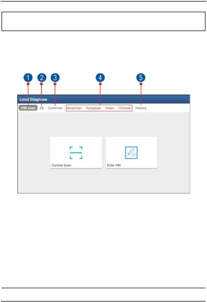
Tap “Local Diagnosis”, a screen similar to the following figure appears:
Fig. 4-8
VINScan button: Tap it to scan the Vehicle Identification Number (VIN) code of your vehicle. OBD VIN and INPUT VIN are included. This function does not apply to the commercial vehicles.
1
*Note: Before using this function, the corresponding diagnostic software and Auto search file need to be downloaded on your tool first while downloading the diagnostic software.
2All Tab: Displays all the vehicle makes in the vehicle menu.
3Common Tab: Displays all frequently-used vehicle makes.
4Regional buttons: Tap different buttons to switch to corresponding
19

LAUNCH |
S3001 User Manual |
vehicles. If you have purchased an S3001of Gasoline & Diesel Version, a Heavy-duty tab will appear next to the regional button.
History Button: Generally once a vehicle diagnosis is performed, S3001 will record the every details of diagnostic process. This
5function provides a quick access to the previously tested vehicles. Testing can be resumed from the previous operation without starting
 from scratch.
4.2.4 Diagnostics toolbar
The diagnostics toolbar contains a number of buttons that enable various procedures. It is displayed at the top of the vehicle diagnostic screen throughout the whole diagnostic session. Refer to the table below for a brief description of the functions of the diagnostics toolbar buttons:
|
|
Fig. 4-9 |
Name |
Icon |
Function |
Home |
|
Return to the Home screen. |
|
|
Tap to print the current screen. To perform |
|
printing, you need to purchase an extra Wi-Fi |
|
|
printer manufactured by LAUNCH separately |
|
|
|
and then properly configure the wireless printer |
|
|
following the steps described in Chapter 15.3. |
20

LAUNCH |
S3001 User Manual |
Testable Model |
Inquires the vehicle models that the |
|
S3001 supports. |
||
|
Personal Center  Quick access to personal center.
Exit |
Exit the diagnostic application. |
4.3 Diagnosis Methods
S3001 tablet supports 2 communication methods with the S3001 VCI device: Wi-Fi and data cable. You may choose any one of the methods to diagnose a vehicle.
*Notes:
To obtain stable communication, you are strongly recommended to perform the vehicle diagnosis via USB cable. In this case, the USB cable is required to connect the S3001 VCI device and the tablet.
When all communication methods are applied at the same time, the S3001 system will use the USB communication as the default priority.
4.4Connections
4.4.1 Preparation
Normal testing conditions
Turn on the vehicle power supply.
Throttle should be in a closed position.
4.4.2 DLC location
The DLC (Data Link Connector) is typically a standard 16 pin connector where diagnostic code readers interface with the vehicle’s on-board computer. The DLC is usually located 12 inches from the center of the instrument panel (dash), under or around the driver’s side for most vehicles. If Data Link Connector is not located under dashboard, a label should be there telling location. For some Asian and European vehicles, the DLC is located behind the ashtray and the ashtray must be removed to access the connector. If the DLC cannot be found, refer to the vehicle’s service manual for the location.
21

LAUNCH |
S3001User Manual |
Fig. 4-11
4.4.3 Vehicle connection (For Passenger Vehicle Version)
The method used to connect the diagnostic connector to a vehicle’s DLC depends on the vehicle’s configuration as follows:
A vehicle equipped with an OBD II management system supplies both communication and 12V power through a standardized DLC.
A vehicle not equipped with an OBD II management system supplies communication through a DLC connection, and in some cases supplies 12V power through the cigarette lighter receptacle or a connection to the vehicle battery.
Follow the steps mentioned below to connect OBD II vehicle:
1.Locate vehicle’s DLC socket.
2.Plug the S3001 VCI device into the vehicle’s DLC socket (It is suggested to use the OBD II extension cable to connect the S3001 VCI device and DLC socket).
Fig. 4-12
3.Choose one of the two ways to obtain power from:
A.Power adaptor: Connect one end of the included power adaptor to DC IN port of S3001 tablet, and the other end to AC outlet. B.
Internal battery pack
For non-OBDII vehicle, proceed as follows:
1.Locate vehicle’s DLC socket.
2.Select the corresponding non-16pin connector.
3.Plug the non-16pin end of the connector into the DLC socket, and the other end to the OBD I adaptor, and then tighten the captive screws.
22
 Loading...