

Page 1

(C) Diagtools & Launch Europe www.diagtools.lv, Riga, Pernavas 43A, LV-1009, t. +371 67704152, +371 29416069
Version: V1.00.000
Revised date: May-10-2017
Page 2

LAUNCH X431 EURO TAB User Manual
(C) Diagtools & Launch Europe www.diagtools.lv, Riga, Pernavas 43A, LV-1009, t. +371 67704152, +371 29416069
Copyright Information
Copyright © 2017 by LAUNCH TECH. CO., LTD. All rights reserved. No part of
this publication may be reproduced, stored in a retrieval system, or transmitted
in any form or by any means, electronic, mechanical, photocopying, recording or
otherwise, without the prior written permission of LAUNCH. The information
contained herein is designed only for the use of this unit. LAUNCH is not
responsible for any use of this information as applied to other units.
Neither LAUNCH nor its affiliates shall be liable to the purchaser of this unit or
third parties for damages, losses, costs, or expenses incurred by purchaser or
third parties as a result of: Accident, misuse, or abuse of this unit, or
unauthorized modifications, repairs, or alterations to this unit, or failure to strictly
comply with LAUNCH operating and maintenance instructions. LAUNCH shall
not be liable for any damages or problems arising from the use of any options or
any consumable products other than those designated as Original LAUNCH
Products or LAUNCH Approved Products by LAUNCH.
Trademark Information
LAUNCH is a registered trademark of LAUNCH TECH CO., LTD. (LAUNCH) in
China and other countries. All other LAUNCH trademarks, service marks,
domain names, logos, and company names referred to in this manual are either
trademarks, registered trademarks, service marks, domain names, logos,
company names of or are otherwise the property of LAUNCH or its affiliates. In
countries where any of the LAUNCH trademarks, service marks, domain names,
logos and company names are not registered, LAUNCH claims other rights
associated with unregistered trademarks, service marks, domain names, logos,
and company names. Other products or company names referred to in this
manual may be trademarks of their respective owners. You may not use any
trademark, service mark, domain name, logo, or company name of LAUNCH or
any third party without permission from the owner of the applicable trademark,
service mark, domain name, logo, or company name. You may contact LAUNCH
by visiting the website at www.cnlaunch.com, or writing to LAUNCH TECH. CO.,
LTD., Launch Industrial Park, North of Wuhe Avenue, Banxuegang, Bantian,
Longgang, Shenzhen, Guangdong, P.R.China, to request written permission to
use Materials on this manual for purposes or for all other questions relating to
this manual.
i
Page 3

LAUNCH X431 EURO TAB User Manual
(C) Diagtools & Launch Europe www.diagtools.lv, Riga, Pernavas 43A, LV-1009, t. +371 67704152, +371 29416069
Important Safety Precautions
Important: To avoid personal injury, property damage, or accidental damage to
the product, read all of the information in this section before using the product.
Never collide, throw, or puncture X-431 EURO TAB, and avoid falling,
extruding and bending it.
Do not insert foreign objects into or place heavy objects on your device.
Sensitive components inside might cause damage.
Do not use X-431 EURO TAB in exceptionally cold or hot, dusty, damp or dry
environments.
In places using X-431 EURO TAB may cause interference or generate a
potential risk, please turn it off.
X-431 EURO TAB is a sealed unit. There are no end-user serviceable parts
inside. All internal repairs must be done by an authorized repair facility or
qualified technician. If there is any inquiry, please contact the dealer.
Never place X-431 EURO TAB into apparatus with strong electromagnetic
field.
Keep X-431 EURO TAB far away from magnetic devices because its
radiations can damage the screen and erase the data stored on X-431 EURO
TAB.
DANGER: Do not attempt to replace the internal rechargeable lithium battery.
Contact the dealer for factory replacement.
CAUTION: Please use the included battery and charger. Risk of explosion if
the battery is replaced with an incorrect type.
Do not disconnect power abruptly when X-431 EURO TAB is being formatted
or in process of uploading or downloading. Or else it may result in program
error.
Do not delete unknown files or change the name of files or directories that
were not created by you, otherwise your X-431 EURO TAB software might
fail to work.
Be aware that accessing network resources can leave your X-431 EURO
TAB vulnerable to computer viruses, hackers, spyware, and other malicious
activities that might damage your device, software or data. It is your
responsibility to ensure that you have adequate protection in the forms of
firewalls, antivirus software, and anti-spyware software and keep such
software up to date.
ii
Page 4

LAUNCH X431 EURO TAB User Manual
(C) Diagtools & Launch Europe www.diagtools.lv, Riga, Pernavas 43A, LV-1009, t. +371 67704152, +371 29416069
Precautions on Using X-431 EURO TAB
Before using this test equipment, please read the following safety information
carefully.
Always perform automotive testing in a safe environment.
If the diagnostic connector remains unused for a long period of time, it is
suggested to unplug the connector from vehicle’s DLC to conserve battery
power.
Wear an ANSI-approved eye shield when testing or repairing vehicles.
The vehicle shall be tested in a well ventilated work area, as engines produce
various poisonous compounds (hydrocarbon, carbon monoxide, nitrogen
oxides, etc.)
Do not connect or disconnect any test equipment while the ignition is on or
the engine is running.
Put blocks in front of the drive wheels and never leave the vehicle unattended
while testing.
Keep the test equipment dry, clean, free from oil, water or grease. Use a mild
detergent on a clean cloth to clear the outside of the equipment as
necessary.
Do not drive the vehicle and operate the test equipment at the same time.
Any distraction may cause an accident.
Keep clothing, hair, hands, tools, test equipment, etc. away from all moving or
hot engine parts.
Before starting the engine, put the gear lever in the Neutral position (for
manual transmission) or in the Park (for automatic transmission) position to
avoid injury.
To avoid damaging the test equipment or generating false data, please make
sure the vehicle battery is fully charged and the connection to the vehicle
DLC (Data Link Connector) is clear and secure.
Automotive batteries contain sulfuric acid that is harmful to skin. In operation,
direct contact with the automotive batteries should be avoided. Keep the
ignition sources away from the battery at all times.
Precautions on Operating Vehicle’s ECU
Do not disconnect battery or any wiring cables in the vehicle when the ignition
switch is on, as this could avoid damage to the sensors or the ECU.
Do not place any magnetic objects near the ECU. Disconnect the power
iii
Page 5

LAUNCH X431 EURO TAB User Manual
(C) Diagtools & Launch Europe www.diagtools.lv, Riga, Pernavas 43A, LV-1009, t. +371 67704152, +371 29416069
supply to the ECU before performing any welding operations on the vehicle.
Use extreme caution when performing any operations near the ECU or
sensors. Ground yourself when you disassemble PROM, otherwise ECU and
sensors can be damaged by static electricity.
When reconnecting the ECU harness connector, be sure it is attached firmly,
otherwise electronic elements, such as ICs inside the ECU, can be damaged.
iv
Page 6

LAUNCH X431 EURO TAB User Manual
(C) Diagtools & Launch Europe www.diagtools.lv, Riga, Pernavas 43A, LV-1009, t. +371 67704152, +371 29416069
TABLE OF CONTENTS
1 INTRODUCTION ............................................................................................ 1
1.1 P
RODUCT PROFILE
1.2 F
EATURES
1.3 T
ECHNICAL SPECIFICATIONS
................................................................................................ 1
2 KNOWLEDGE OF X-431 EURO TAB ............................................................ 4
2.1 X-431 EURO TAB
2.2 VCI C
2.3 P
ONNECTOR (ONLY APPLIES TO
ACKAGE LIST
3 PREPARATIONS ............................................................................................ 8
HARGING
3.1 C
3.2 U
SING BATTERY
OWER ON/OFF
3.3 P
3.3.1 Power on .......................................................................................... 9
3.3.2 Power off .......................................................................................... 9
IPS ON FINGER OPERATIONS
3.4 T
3.5 L
OCK & UNLOCK SCREEN
3.5.1 Lock the screen .............................................................................. 10
3.5.2 Unlock the screen .......................................................................... 10
3.6 S
CREEN LAYOUT
OTIFICATION PANEL
3.7 N
3.8 A
DJUST BRIGHTNESS
ET STANDBY TIME
3.9 S
3.10 S
ET SCREEN LOCK
ETWORK SETTING
3.11 N
3.11.1 Wired Connection ......................................................................... 12
3.11.2 Connect to a Wi-Fi network .......................................................... 12
4 INITIAL USE ................................................................................................. 13
ETTING STARTED
4.1 G
4.2 R
EGISTER & DOWNLOAD DIAGNOSTIC SOFTWARE
4.2.1 User registration ............................................................................. 13
4.2.2 Function menu ............................................................................... 16
IAGNOSIS METHODS
4.3 D
.................................................................................... 1
...................................................................... 2
TABLET
........................................................................ 5
CARS
12V
) ......................................... 6
.......................................................................................... 7
X-431 EURO TAB ................................................................... 8
........................................................................................ 9
........................................................................................ 9
................................................................... 9
........................................................................ 10
..................................................................................... 10
.............................................................................. 11
.............................................................................. 11
................................................................................. 11
................................................................................ 11
............................................................................... 12
.................................................................................. 13
.................................... 13
.............................................................................. 16
v
Page 7

LAUNCH X431 EURO TAB User Manual
(C) Diagtools & Launch Europe www.diagtools.lv, Riga, Pernavas 43A, LV-1009, t. +371 67704152, +371 29416069
4.4 C
ONNECTIONS
........................................................................................ 17
4.4.1 Preparation..................................................................................... 17
4.4.2 DLC location .................................................................................. 17
4.4.3 Vehicle connection ......................................................................... 18
5 DIAGNOSIS & RESET ................................................................................. 20
TART DIAGNOSTICS
5.1 S
EALTH REPORT (QUICK TEST
5.1 H
............................................................................... 20
) ............................................................... 22
5.1.1 View fault report ............................................................................. 22
5.1.2 Clear DTC ...................................................................................... 24
YSTEM SCAN
5.2 S
5.3 S
YSTEM SELECTION
........................................................................................ 24
................................................................................ 24
5.3.1 Version Information ........................................................................ 25
5.3.2 Read Fault Code ............................................................................ 26
5.3.3 Clear Fault Memory ........................................................................ 27
5.3.4 Read Data Stream .......................................................................... 27
5.1.5 How to view diagnostic history? ..................................................... 29
PECIAL (RESET) FUNCTION
5.2 S
.................................................................... 30
6 SOFTWARE UPDATE .................................................................................. 33
7 GOLO BUSINESS MANAGER ..................................................................... 34
8 REMOTE DIAGNOSIS ................................................................................. 36
8.1 I
NTERFACE LAYOUT
8.2 A
DD FRIENDS
TART INSTANT MESSAGING
8.3 S
8.4 L
AUNCH REMOTE DIAGNOSIS
................................................................................. 36
.......................................................................................... 36
.................................................................... 37
................................................................... 38
9 SENSORBOX (TOOLBOX) .......................................................................... 41
RODUCT SUMMARY
9.1 P
9.2 S
TRUCTURE & ACCESSORIES
............................................................................... 41
.................................................................. 42
9.2.1 Sensorbox structure ....................................................................... 42
9.2.2 Sensorbox accessories .................................................................. 43
9.3 S
ENSOR SIMULATION
.............................................................................. 43
9.3.1 Connections ................................................................................... 43
9.3.2 Simulation test................................................................................ 44
9.3.3 Precautions on checking vehicle sensor ......................................... 48
vi
Page 8

LAUNCH X431 EURO TAB User Manual
(C) Diagtools & Launch Europe www.diagtools.lv, Riga, Pernavas 43A, LV-1009, t. +371 67704152, +371 29416069
10 MULTIMETER (TOOLBOX) ........................................................................ 50
10.1 M
10.2 T
AIN MENU
EST SAMPLE
........................................................................................... 50
....................................................................................... 51
11 BATTERYBOX (TOOLBOX) ....................................................................... 53
RODUCT SUMMARY
11.1 P
EST ENVIRONMENT
11.2 T
............................................................................. 53
.............................................................................. 54
11.2.1 Test environment .......................................................................... 54
11.2.2 Battery status and description ...................................................... 54
11.3 B
ATTERYBOX STRUCTURE & ACCESSORIES
............................................ 55
11.3.1 Batterybox structure ..................................................................... 55
11.3.2 Test accessories ........................................................................... 55
ONNECTIONS & OPERATIONS
11.4. C
.............................................................. 55
11.4.1 Connection ................................................................................... 55
11.4.2 Inside the vehicle test ................................................................... 56
11.4.3 Outside the vehicle test ................................................................ 59
RECAUTIONS ON BATTERY TEST
11.5 P
.......................................................... 59
12 OSCILLOSCOPE (TOOLBOX)................................................................... 61
12.1 I
NTRODUCTION
12.2 S
TRUCTURE & ACCESSORIES
...................................................................................... 61
................................................................ 62
12.2.1 Scopebox structure ...................................................................... 62
12.2.2 Scopebox accessories ................................................................. 63
ONNECTION & INITIAL USE
12.3 C
................................................................... 64
12.3.1 Connection ................................................................................... 64
12.3.2 Initial interface introduction ........................................................... 64
PERATIONS
12.4 O
......................................................................................... 65
12.4.1 Channel selection and attributes setting ....................................... 65
12.4.2 Auto .............................................................................................. 70
12.4.3 View Settings ............................................................................... 70
12.4.4 Measure ....................................................................................... 71
12.4.5 File management ......................................................................... 73
12.4.6 Expert reference ........................................................................... 74
13 MY DATA .................................................................................................... 76
13.1 MY R
13.2 MY C
EPORT
.......................................................................................... 76
ONNECTOR
................................................................................... 77
vii
Page 9

LAUNCH X431 EURO TAB User Manual
(C) Diagtools & Launch Europe www.diagtools.lv, Riga, Pernavas 43A, LV-1009, t. +371 67704152, +371 29416069
13.3 D
IAGNOSTIC CONNECTOR CONNECTION MANAGEMENT
13.4 A
CTIVATE CONNECTOR
13.5 F
IRMWARE FIX
ROFILE
13.6 P
13.7 C
HANGE PASSWORD
...................................................................................... 78
............................................................................................... 78
.......................................................................... 78
.............................................................................. 78
............................ 77
14 SETTINGS .................................................................................................. 79
NITS OF MEASUREMENT
14.1 U
14.2 P
RINT INFORMATION
14.3 L
AUNCH PRINTER CONNECTION
ETWORK TEST
14.4 N
14.5 A
14.6 L
.................................................................................................. 82
BOUT
OG OUT
..................................................................................... 82
.............................................................................................. 82
...................................................................... 79
.............................................................................. 79
............................................................. 79
15 WI-FI PRINTER .......................................................................................... 83
15.1 G
ENERAL CONTROLS
HERMAL PAPER LOADING
15.2 T
SING THE RECHARGEABLE BATTERY
15.3 U
15.4 P
RINTER CONNECTION
15.5 H
OW TO PRINT TEST RESULTS
............................................................................. 83
..................................................................... 84
..................................................... 86
........................................................................... 87
? .............................................................. 87
16 OTHERS ..................................................................................................... 89
16.1 E
................................................................................................... 89
MAIL
16.1.1 Configure an email account .......................................................... 89
16.1.2 Add an email account ................................................................... 89
ROWSER
16.2 B
............................................................................................. 89
16.2.1 Open browser............................................................................... 89
16.2.2 Download files .............................................................................. 90
16.3 S
YNCHRONIZATION
................................................................................ 90
16.3.1 Connect to PC .............................................................................. 90
16.3.2 Run on PC ................................................................................... 90
16.3.3 Install an application ..................................................................... 91
16.4 C
LEAR CACHE
....................................................................................... 91
17 FAQ ............................................................................................................ 92
viii
Page 10

LAUNCH X431 EURO TAB User Manual
(C) Diagtools & Launch Europe www.diagtools.lv, Riga, Pernavas 43A, LV-1009, t. +371 67704152, +371 29416069
1 Introduction
1.1 Product Profile
X-431 EURO TAB is a new Android-based vehicle trouble diagnostic tool
developed by LAUNCH.
It features wired network, meanwhile it also supports WLAN communication,
which enables you to surf the Internet, update App and diagnostic software
online, perform remote diagnostics, getting your job faster and easier.
Featuring Android 4.4 operating system, 2.0GHz 8-core CPU and 10.1” HD
display, it has functions of vehicle diagnosis, oscilloscope, ignition, sensor,
multimeter, browser and battery test etc. High definition multimedia output
extending display function is available. As a result, it has strong practicability
and high performance-price ratio, which is a helpful assistant for vehicle repair
and maintenance.
1.2 Features
1. Diagnose:
VINscan quick test and manual diagnosis are available. Diagnosis functions
include: Read DTCs, Clear DTCs, Read Data Stream, Special Functions etc.
Remote diagnosis: This option aims to help repair shops or technicians
launch instant messaging and remote diagnosis, making the repair job getting
fixed faster.
Special function: All kinds of maintenance and reset functions can be done.
One-click Update: Lets you update your diagnostic software online.
Diagnostic feedback: Enables you to submit the vehicle issue to us for
analysis and troubleshooting.
2. WLAN connection and Ethernet connection are supported.
3. High definition output interface is provided for connecting the external
projectors or displays.
4. Equipped with Universal Serial BUS port for connecting the add-on modules
such as Scopebox, Sensorbox and Batterybox.
5. Web browser: Users can make online search and visit any website.
1
Page 11

LAUNCH X431 EURO TAB User Manual
(C) Diagtools & Launch Europe www.diagtools.lv, Riga, Pernavas 43A, LV-1009, t. +371 67704152, +371 29416069
1.3 Technical Specifications
A. X-431 EURO TAB Tablet
Item Description
Operating system Android 4.4
CPU 8-core Processor, 2.0GHz
Display 10.1 inch touch screen with 1920 x 1200P resolution
Memory 2GB
Hard disk 64GB (Expandable to 128GB via TF card)
Connectivity Ethernet/Wi-Fi (802.11 b/g/n)
Camera 2.0MP front-facing camera + 8.0MP rear-facing camera
Sensor
Audio
Input/Output
Battery 15000 mAh lithium-polymer battery
Operating Temp. -10℃ ~ 55℃(14 ~131℉)
Storage Temp. -20℃ ~ 70℃(-4 ~158℉)
B. VCI Connector
USB: 2.0
Bluetooth 2.0
Gravity Accelerometer
Microphone
Speakers
3.5mm stereo headset jack
Item Descriptions
Working Voltage DC 9V ~ 18V
Working Current About 85mh
Standby Current About 55mh
Dimension 70mm x 42.5mm x 20mm
Weight < 100g
Working Temp. -10℃ ~ 55℃(14 ~131℉)
2
Page 12

LAUNCH X431 EURO TAB User Manual
(C) Diagtools & Launch Europe www.diagtools.lv, Riga, Pernavas 43A, LV-1009, t. +371 67704152, +371 29416069
Storage Temp. -20℃ ~ 70℃(-4 ~158℉)
Relative Humidity 20% ~ 90%
3
Page 13
LAUNCH X431 EURO TAB User Manual
(C) Diagtools & Launch Europe www.diagtools.lv, Riga, Pernavas 43A, LV-1009, t. +371 67704152, +371 29416069
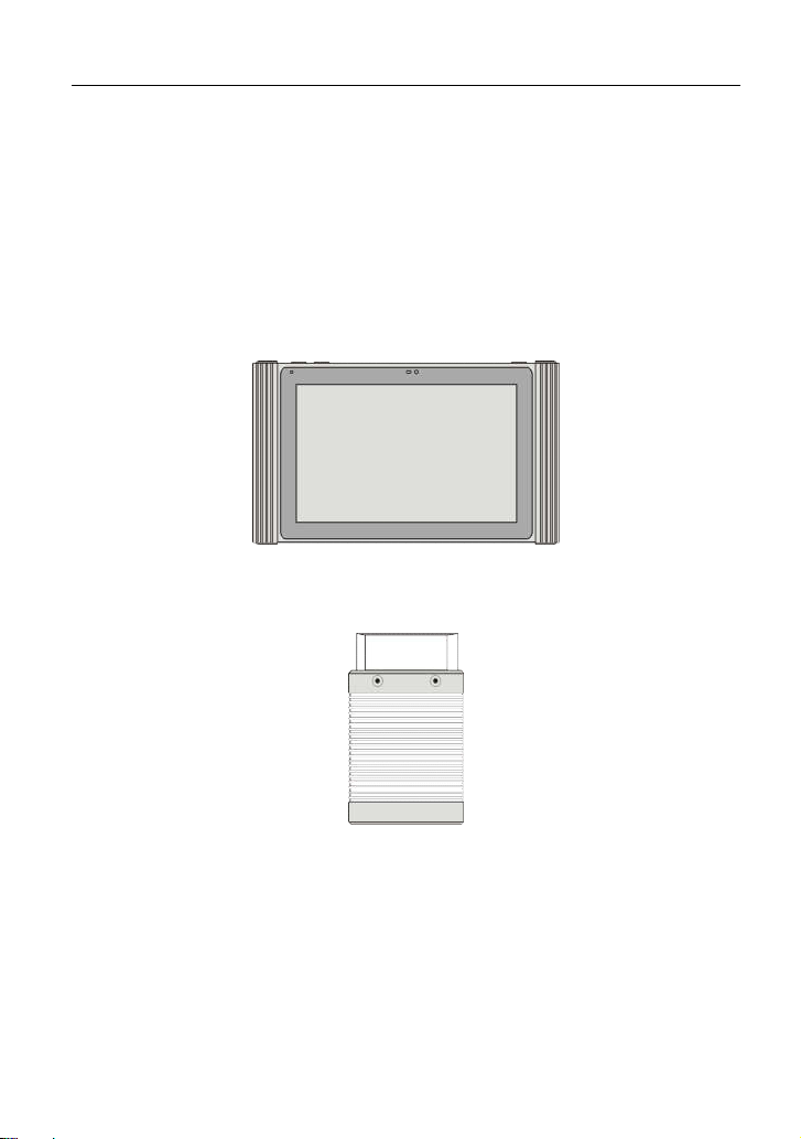
2 Knowledge of X-431 EURO TAB
The X-431 EURO TAB system is mainly composed of one X-431 EURO TAB
tablet (See Chapter “2.1”), one docking station and one VCI connector (See
Chapter “2.2”).
X-431 EURO TAB tablet – the central processor and monitor for the system
(See Chapter “2.1”).
Fig. 2-1 X-431 EURO TAB tablet
VCI connector – the device for accessing vehicle data (See Chapter “2.2”).
Fig. 2-2 VCI connector
4
Page 14
LAUNCH X431 EURO TAB User Manual
(C) Diagtools & Launch Europe www.diagtools.lv, Riga, Pernavas 43A, LV-1009, t. +371 67704152, +371 29416069
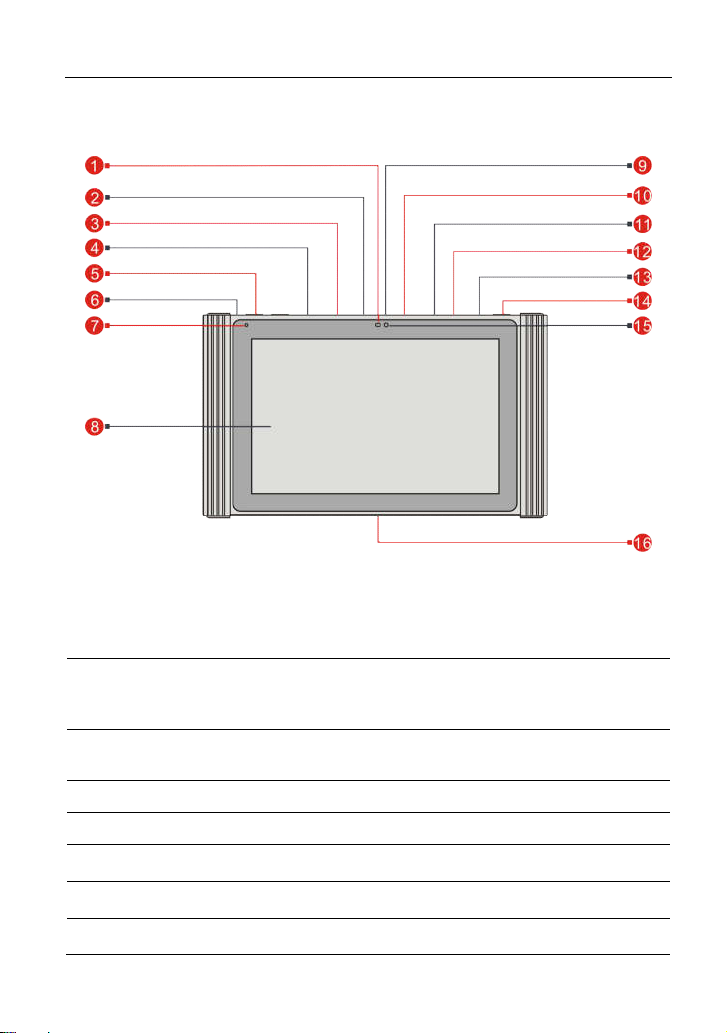
2.1 X-431 EURO TAB tablet
Fig. 2-3 X-431 EURO TAB tablet
Ambient Light
1
Sensor
To connect add-on USB modules (Scopebox,
2 USB2 Port
Sensorbox or Batterybox) while extending
X-431 EURO TAB function.
3 Ethernet Port
To connect the Ethernet cable for wired
network.
4 DC IN Port To connect the included power adaptor.
5 VOLUME +/- Key To adjust the volume.
6 Reset Switch
7 Microphone
8 Touch Screen
To restart the tablet.
5
Page 15
LAUNCH X431 EURO TAB User Manual
(C) Diagtools & Launch Europe www.diagtools.lv, Riga, Pernavas 43A, LV-1009, t. +371 67704152, +371 29416069
9 USB1 Port Only reserved for Micro USB cable.
10 HDMI Port
11 Memory Card Slot To insert a memory card for storage extension.
12 SIM Card Slot Only reserved for future use.
13 Earphone Jack
POWER/Screen
14
Lock Key
15 Front Camera
16 Charging Slot To recharge X-431 EURO TAB.
To connect an external projector or monitor with
HDMI interface.
In Off mode, press it to turn on the X-431 EURO
TAB tablet.
In On mode:
Press it to activate the LCD if the LCD is off.
Press it to turn off the LCD if the LCD lights up.
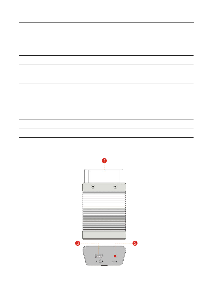
2.2 VCI Connector (Only applies to 12V cars)
Fig. 2-4 VCI Connector
6
Page 16

LAUNCH X431 EURO TAB User Manual
(C) Diagtools & Launch Europe www.diagtools.lv, Riga, Pernavas 43A, LV-1009, t. +371 67704152, +371 29416069
OBD-16 diagnostic
1
connector
2 Mini USB port
To connect on vehicle’s OBD II DLC.
For connecting the USB cable to X-431 EURO
TAB.
There are 3 modes available:
It illuminates Red while the connector is
plugged into the vehicle’s DLC.
3 Mode Indicators
Blue indicates it is working in Bluetooth
mode.
It illuminates Green when the connector is
connected to X-431 EURO TAB via USB
cable.
2.3 Package List
Common accessories for each X-431 EURO TAB are same, but for different
destinations, the accessories of X-431 EURO TAB may vary. Please consult
from the local agency or check the packing list supplied with X-431 EURO TAB
together.
X-431 EURO TAB tablet …………………...……...………………………….x 1
Docking station………………………………………………………...……….x 1
VCI connector …………………………………….……………….….……….x 1
Power adaptor ………………………………………………………...……….x 1
OBD II extension cable……………………………………………...……….x 1
OBD I adaptor………………………………………..……………......……….x 1
Cigarette lighter cable………………………………………………...……….x 1
Battery clamps cable………………………………………………...……….x 1
USB cable……………………………………………………………...……….x 1
Password envelope…………………………………………………...……….x 1
Ethernet crossover cable…………..………………………………………….x 1
BMW F chassis programming line ………………………………………….x 1
Wi-Fi printer…………………………………………………………...……….x 1
Non-16pin diagnostic connector kit ………………………..…….….……….x 1
Quick Start Guide …………………………………….……..…….….……….x 1
7
Page 17
LAUNCH X431 EURO TAB User Manual
(C) Diagtools & Launch Europe www.diagtools.lv, Riga, Pernavas 43A, LV-1009, t. +371 67704152, +371 29416069
3 Preparations
3.1 Charging X-431 EURO TAB
Choose any one of the followings to charge your X-431 EURO TAB:
A. Use the included 5V power adaptor: Connect one end of the power adaptor to
DC IN port of X-431 EURO TAB, and the other end to the AC outlet. Never
use other similar adaptors other than the included one to charge X-431
EURO TAB.
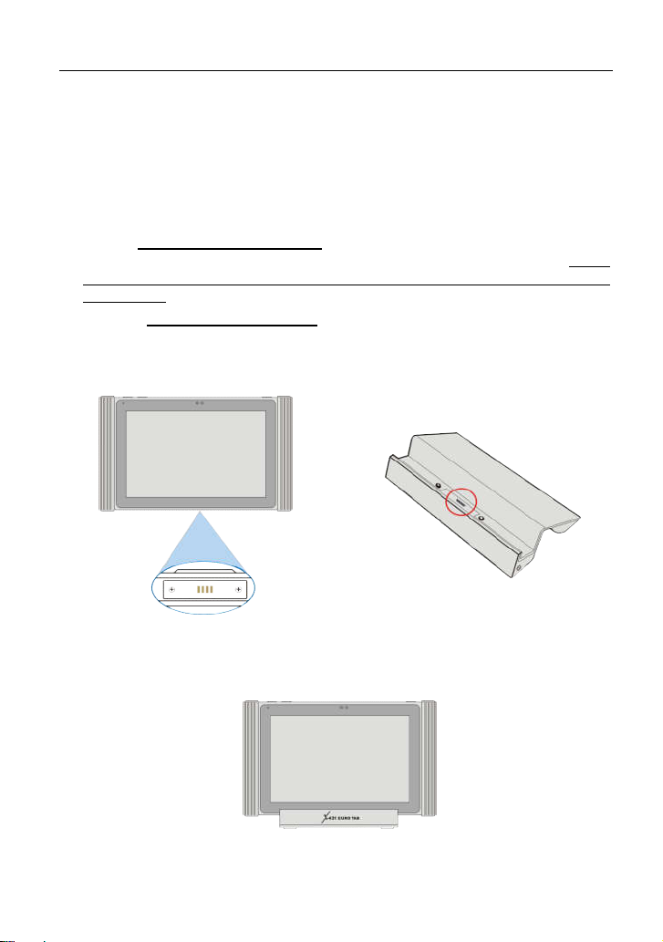
B. Use the docking station(optional): Follow the steps described as below to
charge your X-431 EURO TAB:
1. Locate the charging slot on the bottom of X-431 EURO TAB tablet and the
docking station. See Fig. 3-1 & Fig. 3-2.
Fig. 3-1 Fig. 3-2
2. Align the charging slots, and then dock the tablet into the station to ensure
that it firmly sits on the docking station. Refer to Fig. 3-3.
Fig. 3-3
3. Insert one end of the power cord of the docking station into the power jack,
8
Page 18

LAUNCH X431 EURO TAB User Manual
(C) Diagtools & Launch Europe www.diagtools.lv, Riga, Pernavas 43A, LV-1009, t. +371 67704152, +371 29416069
and then plug the other end into the AC outlet. If appears on the screen, it
indicates it is being charged.
4. If the logo changes into , it indicates that the battery is fully charged.
3.2 Using Battery
If the battery remains unused for a long period of time or the battery is
completely discharged, it is normal that the tool will not power on while being
charged. Please charge it for a period of 5 minutes and then turn it on.
Please use the included power adaptor to charge your tool. No responsibility
can be assumed for any damage or loss caused as a result of using power
adaptors other than the one supplied.
While X-431 EURO TAB has low battery, a beep will sound. If it is very low,
X-431 EURO TAB will be switched off automatically.
3.3 Power On/Off
3.3.1 Power on
Press [POWER] to turn the tool on.
Note: If it is the first time you have used this tool or the tool remains idle for a long
period of time, the tool could fail to turn on. Please charge the tool for a minimum of 5
minutes and attempt to turn on again.
3.3.2 Power off
Press [POWER] for 3 seconds, an option menu will pop up on the screen. Tap
“Power off” to turn the tool off.
To perform a forced shutdown, press [POWER] for more than 8 seconds until
the screen goes dark.
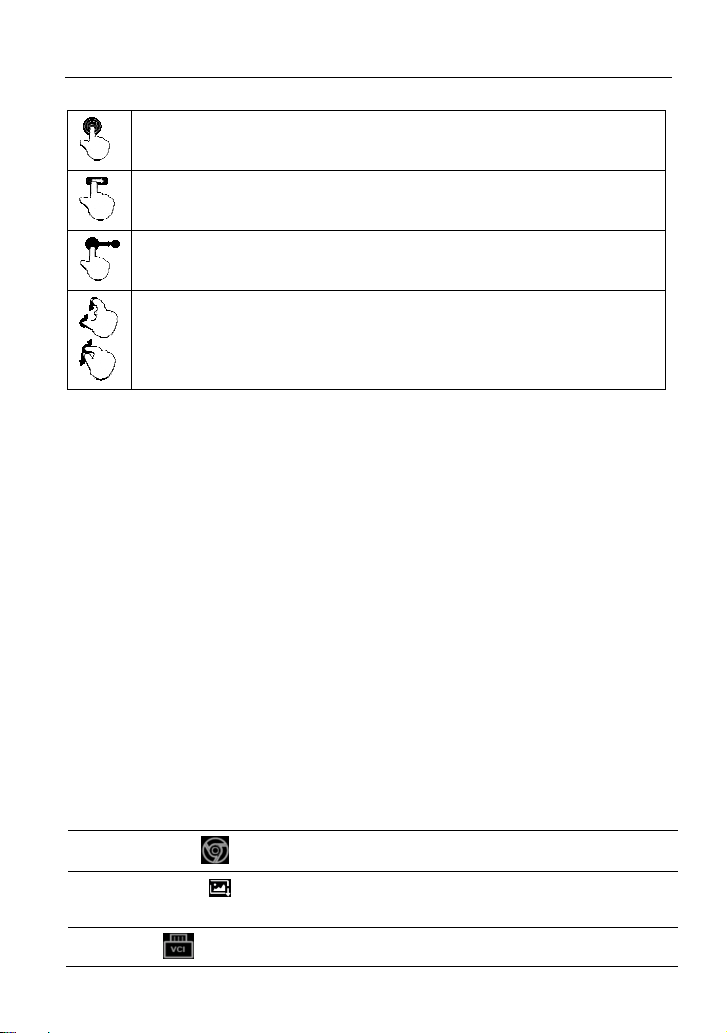
3.4 Tips On Finger Operations
Single-tap: To select a item or launch a program.
Double-tap: To zoom in so that the text on a webpage appears in a
column that fits your device’s screen.
9
Page 19
LAUNCH X431 EURO TAB User Manual
(C) Diagtools & Launch Europe www.diagtools.lv, Riga, Pernavas 43A, LV-1009, t. +371 67704152, +371 29416069
Long press: Tap and hold on the current interface or area until a
contextual menu pops up on the screen, and then release it.
Slide: To jump to different pages.
Drag: Tap the desktop icon and drop it to other location.
Spread apart/pinch together: To zoom in manually, place two
fingers on the screen and then spread them apart. To zoom out,
place two fingers apart on the screen and then pinch them together.
3.5 Lock & Unlock Screen
Many screen lock modes are available on X-431 EURO TAB.
Note: You are recommended to set screen lock as “None” since X-431 EURO TAB is a
frequently used diagnostic tool.
3.5.1 Lock the screen
When it is ON, press [POWER] once to lock the screen.
The system will lock the screen automatically after X-431 EURO TAB
remains idle over the preset standby time.
3.5.2 Unlock the screen
Press [POWER] to activate the screen and drag the lock to “Unlock” position.
Note: If you define as unlock using the pattern, you have to draw the right target pattern
to unlock it.
3.6 Screen Layout
On-screen keys and status bar are as follows:
1
Tap to visit the official website.
2 Tap
3
to capture the current screen and all captured
screenshots are stored in the Screenshots folder.
shows whether the VCI connector is connected properly or
10
Page 20

LAUNCH X431 EURO TAB User Manual
(C) Diagtools & Launch Europe www.diagtools.lv, Riga, Pernavas 43A, LV-1009, t. +371 67704152, +371 29416069
not. If connected, a tick icon appearing on the button indicates the
tablet is communicating with the VCI connector.
4
Tap to return to the Android System’s home screen.
5 Tap to display a list of applications that are currently running
or recently used. To open an application, tap it. To remove an
application, swipe it upwards.
6 Tap to return to the previous screen or exit an application.
3.7 Notification Panel
The notification bar is used to display some activities, such as new message, to
do list and running tasks. You can also open the notification bar to view the
reminder or activity notification.
3.8 Adjust Brightness
Tips: Reducing the brightness of the screen is helpful to save the power of X-431
EURO TAB.
1. On the home screen, tap Settings -> Display -> Brightness level.
2. Drag the slider to adjust it.
3.9 Set Standby Time
If no activities are made within the defined standby period, the screen will be
locked automatically and the system enters sleep mode to save power.
1. On the home screen, tap Settings -> Display -> Sleep.
2. Choose the desired sleep time.
3.10 Set Screen lock
This function is designed to lock the screen and buttons to avoid accidental
operations while X-431 EURO TAB keeps unused.
1. On the home screen, tap Settings -> Security -> Screen lock.
2. Choose the desired screen lock mode and follow the on-screen instructions to
finish your setting.
Note: You are recommended to set screen lock as “None” since X-431 EURO TAB is a
11
Page 21

LAUNCH X431 EURO TAB User Manual
(C) Diagtools & Launch Europe www.diagtools.lv, Riga, Pernavas 43A, LV-1009, t. +371 67704152, +371 29416069
frequently used diagnostic tool.
3.11 Network Setting
There are 2 kinds of network connection available on X-431 EURO TAB.
3.11.1 Wired Connection
1. Connect the Ethernet crossover cable to X-431 EURO TAB directly.
2. On the home screen, tap “Settings” -> “More” -> “Ethernet” and then check
the box “Use the Ethernet”.
3.11.2 Connect to a Wi-Fi network
X-431 EURO TAB has built-in Wi-Fi that can be used to get online. Once you’re
online, you can register your X-431 EURO TAB, browse the Internet, get and
update apps and send email on your network.
Note: Once WLAN is set as ON, X-431 EURO TAB will consume more power. While
WLAN keeps unused, please turn it off to conserve battery power.
1. On the home screen, tap Settings -> WLAN.
2. Tap or slide the WLAN switch to ON, X-431 EURO TAB starts searching for
all available wireless LANs.
3. Choose the desired Wi-Fi access point / network,
If the network you chose is open, you can connect directly;
If the selected network is encrypted, you have to enter the right security
key (network password).
When this tool is in range, it will connect to the previously linked network
automatically.
12
Page 22

LAUNCH X431 EURO TAB User Manual
(C) Diagtools & Launch Europe www.diagtools.lv, Riga, Pernavas 43A, LV-1009, t. +371 67704152, +371 29416069
4 Initial Use
4.1 Getting Started
For new users, please follow the operation chart shown in Fig. 4-1 to start using
X-431 EURO TAB.
Fig. 4-1
Note*: If “VIN Scan” function is performed, this step shall not apply.
4.2 Register & Download Diagnostic Software
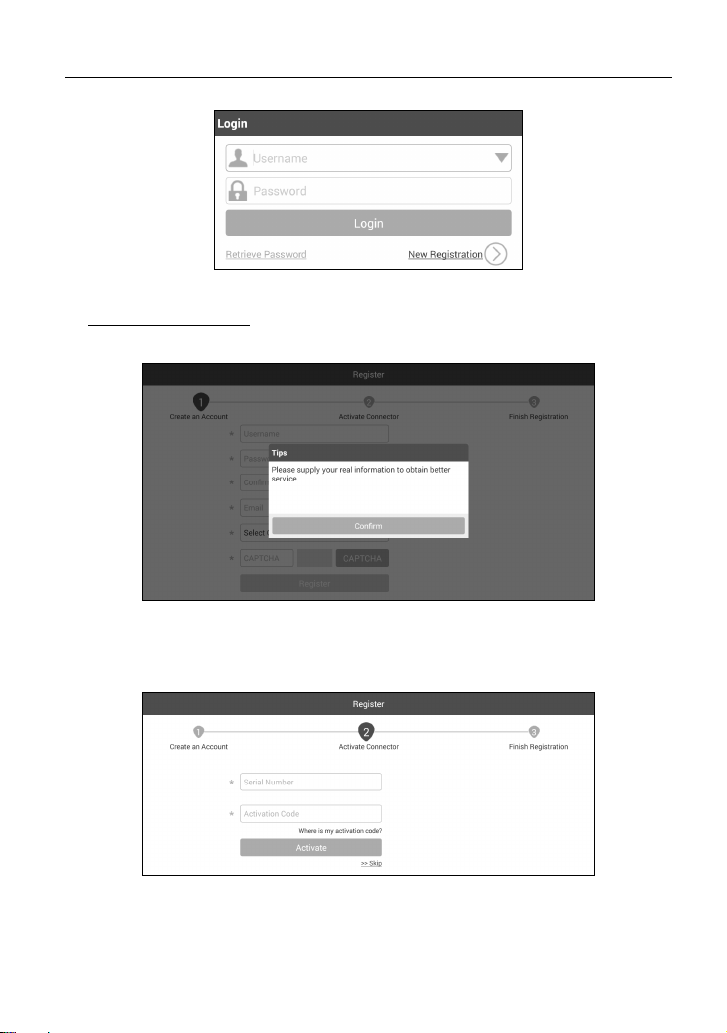
4.2.1 User registration
On the home screen, tap the application icon to launch it, and then tap “Login” to
enter the login interface of diagnosis software.
13
Page 23
LAUNCH X431 EURO TAB User Manual
(C) Diagtools & Launch Europe www.diagtools.lv, Riga, Pernavas 43A, LV-1009, t. +371 67704152, +371 29416069
Fig. 4-2
1. If you are a new user, tap “New Registration” to enter the sign-up page. See
Fig. 4-3.
Fig. 4-3
In Fig. 4-3, fill in the information in each field (Items with * must be filled). After
inputting, tap “Register”, a screen similar to the following will appear:
Fig. 4-4
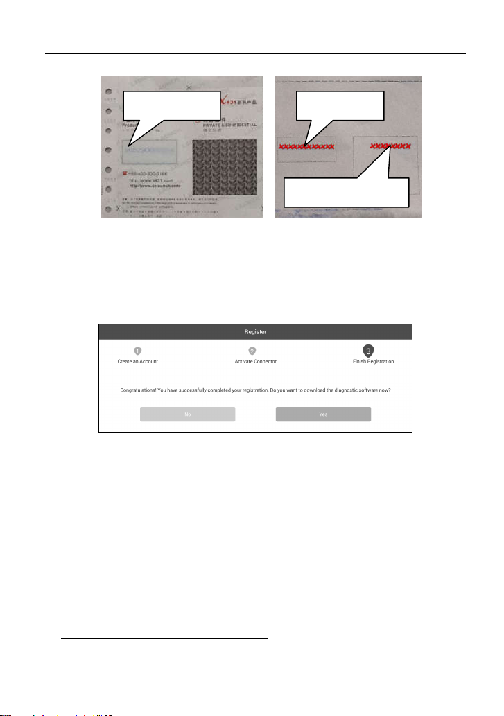
In Fig. 4-4, input the Serial Number and Activation Code, which can be found in
the password envelope.
14
Page 24
LAUNCH X431 EURO TAB User Manual
(C) Diagtools & Launch Europe www.diagtools.lv, Riga, Pernavas 43A, LV-1009, t. +371 67704152, +371 29416069
Product SN
Product SN
Activation code
Note: To exit and activate it later, tap “Skip”. In this case, you can activate your
connector by tapping “Activate Connector” in “My Data”. For details, please refer to
Chapter 13.4.
Tap “Activate” to finish your registration. See Fig. 4-6.
Fig. 4-5
Fig. 4-6
To download the diagnostic software, tap “Yes” to enter the download page.
Tap “No” to download and install it later.
On download page, tap “Update” to start downloading. To pause downloading,
tap “Stop”. To resume it, tap “Continue”. Once download is complete, the system
will install the software package automatically.
Notes:
In process of download, please make sure the tablet has a strong Wi-Fi signal. It
may take several minutes to finish it, please be patient to wait.
To use the VINScan function, you have to download the corresponding diagnostic
software and AutoSearch file.
2. If you have registered to be a member, input your name and password, and
then tap the “Login” button to enter the main menu screen directly.
The X-431 EURO TAB has an auto-save function. Once the username and
Note:
15
Page 25

LAUNCH X431 EURO TAB User Manual
(C) Diagtools & Launch Europe www.diagtools.lv, Riga, Pernavas 43A, LV-1009, t. +371 67704152, +371 29416069
password are correctly entered, the system will automatically store it. Next time you
login the system, you will not be asked to input the account manually.
3. If you forgot the password, tap “Retrieve password” and then follow the
on-screen prompts to reset a new password.
4.2.2 Function menu
Swipe the screen from the right to display the function menu. It mainly includes
the following items:
Name Description
Diagnose
Special Functions
Software Upgrade To update vehicle diagnostic software.
Remote Diagnosis
Diagnostic
Feedback
Maintenance Help
Toolbox
My Data
Configures X-431 EURO TAB to operate as a
diagnostic tool.
To perform some maintenance items, including
electronic throttle position reset, ABS bleeding, oil
lamp reset etc.
This option aims to help repair shops or technicians to
get the repair job fixed faster.
To feed back the recent 10 diagnostic logs to us for
issue analysis.
Includes How-to Videos, operation skills and user
manual etc.
Includes browser, oscilloscope, sensor, multimeter,
battery, etc.
To manage My Connector, My Report, Change
Password and Logout etc.
Settings Allows you to configure system settings.
Custom
Use this option to append the frequently used module
into the function menu screen.
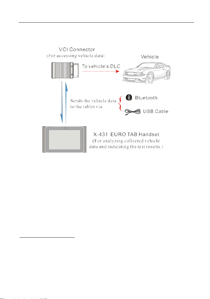
4.3 Diagnosis Methods
X-431 EURO TAB tablet supports 2 communication methods with the VCI
16
Page 26
LAUNCH X431 EURO TAB User Manual
(C) Diagtools & Launch Europe www.diagtools.lv, Riga, Pernavas 43A, LV-1009, t. +371 67704152, +371 29416069
connector: wireless Bluetooth and USB cable. You may choose any one of the
methods to diagnose a vehicle.
Fig. 4-7
Notes:
While using the diagnosis via Bluetooth, the VCI connector should be paired with
the X-431 EURO TAB tablet. If no Bluetooth setting is done before diagnostic
software is launched, you can also configure it while using the software.
To obtain stable communication, you are strongly recommended to perform the
vehicle diagnosis via USB cable. In this case, the USB cable is required to connect
the VCI connector and the X-431 EURO TAB tablet.
4.4 Connections
4.4.1 Preparation
Normal testing conditions
Turn on the vehicle power supply.
Vehicle battery voltage range should be 9-14Volts.
Throttle should be in a closed position.
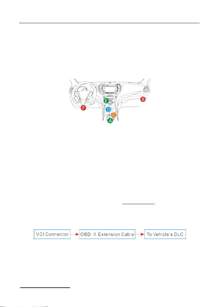
4.4.2 DLC location
The DLC (Data Link Connector) is typically a standard 16 pin connector where
17
Page 27
LAUNCH X431 EURO TAB User Manual
(C) Diagtools & Launch Europe www.diagtools.lv, Riga, Pernavas 43A, LV-1009, t. +371 67704152, +371 29416069
diagnostic code readers interface with the vehicle’s on-board computer. The
DLC is usually located 12 inches from the center of the instrument panel (dash),
under or around the driver’s side for most vehicles. If Data Link Connector is not
located under dashboard, a label should be there telling location. For some
Asian and European vehicles, the DLC is located behind the ashtray and the
ashtray must be removed to access the connector. If the DLC cannot be found,
refer to the vehicle’s service manual for the location.
Fig. 4-8
4.4.3 Vehicle connection
The method used to connect the diagnostic connector to a vehicle’s DLC
depends on the vehicle’s configuration as follows:
A vehicle equipped with an OBD II management system supplies both
communication and 12V power through a standardized DLC.
A vehicle not equipped with an OBD II management system supplies
communication through a DLC connection, and in some cases supplies 12V
power through the cigarette lighter receptacle or a connection to the vehicle
battery.
Follow the steps mentioned below to connect OBD II vehicle:
1. Locate vehicle’s DLC socket.
2. Plug the VCI connector into the vehicle’s DLC socket (It is suggested to use
the OBD II extension cable to connect the VCI connector and DLC socket.).
Fig. 4-9
3. Choose one of the two ways to obtain power from:
A. Power adaptor: Connect one end of the included power adaptor to DC IN
port of X-431 EURO TAB tablet, and the other end to AC outlet.
B. Internal battery pack
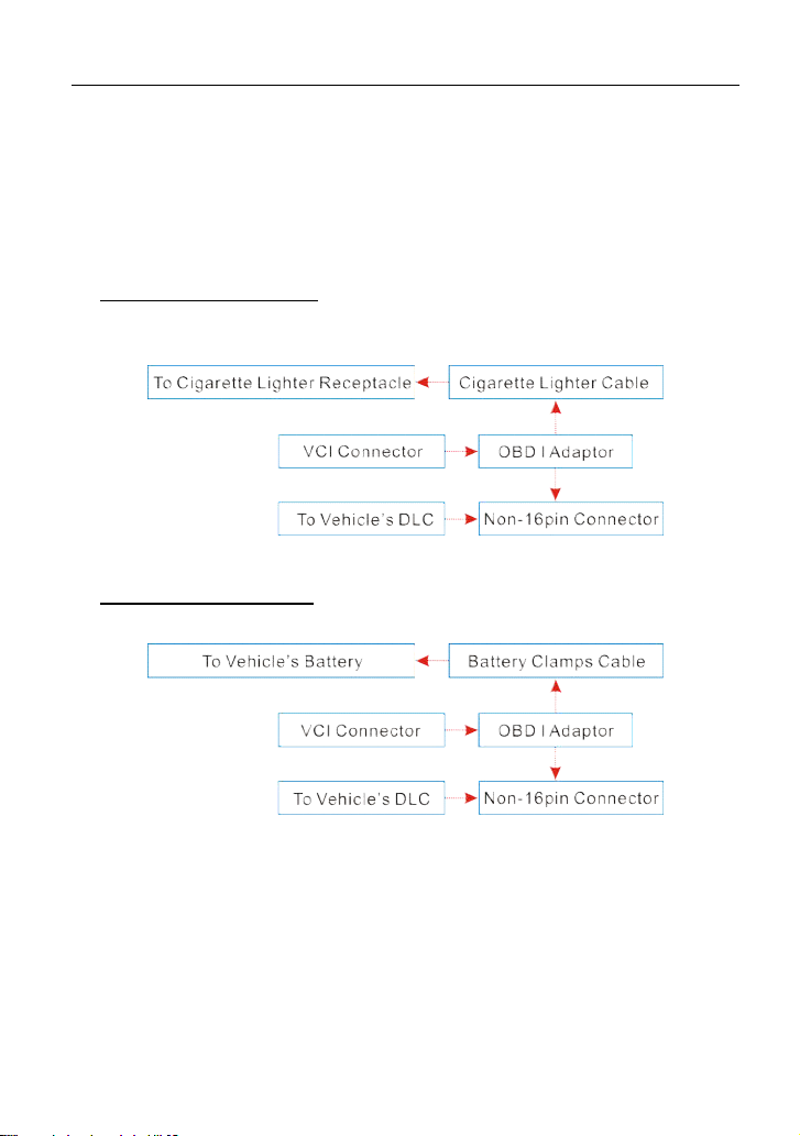
For non-OBDII vehicle, proceed as follows:
18
Page 28
LAUNCH X431 EURO TAB User Manual
(C) Diagtools & Launch Europe www.diagtools.lv, Riga, Pernavas 43A, LV-1009, t. +371 67704152, +371 29416069
1. Locate vehicle’s DLC socket.
2. Select the corresponding non-16pin connector.
3. Plug the non-16pin end of the connector into the DLC socket, and the other
end to the OBD I adaptor, and then tighten the captive screws.
4. Connect the other end of the adaptor to the included VCI connector.
5. To supply power to OBD I adaptor from:
A. Cigarette Lighter Cable: Connect one end of the cigarette lighter cable to
vehicle’s cigarette lighter receptacle, and the other end to the power jack of
OBD I adaptor.
Fig. 4-10
B. Battery Clamps Cable: Connect one end of the battery clamps cable to
vehicle’s battery, and the other end to the power jack of OBD I adaptor.
Fig. 4-11
19
Page 29
LAUNCH X431 EURO TAB User Manual
(C) Diagtools & Launch Europe www.diagtools.lv, Riga, Pernavas 43A, LV-1009, t. +371 67704152, +371 29416069
5 Diagnosis & Reset
5.1 Start Diagnostics
Tap “Diagnose” to enter the vehicle selection page.
2 approaches are provided for you to access the vehicle diagnostic software.
Choose any one of the following ways:
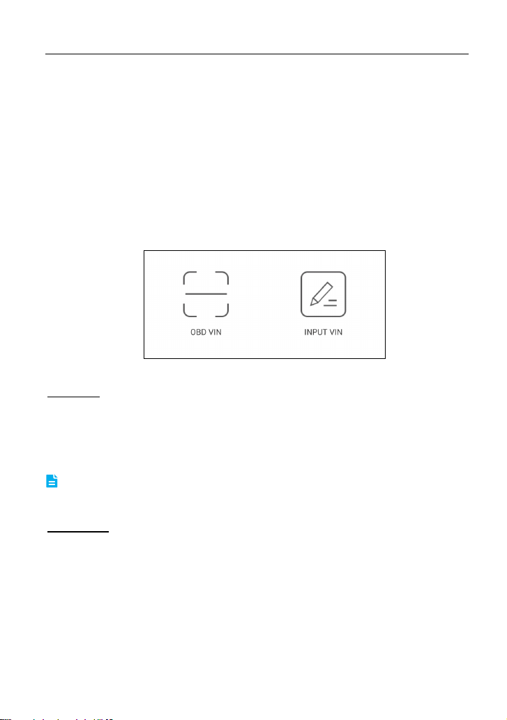
1. VINSCAN enables you to access it more quickly.
In this case, automatic scan (OBD VIN) and manual input (INPUT VIN) are
available.
OBD VIN: In this mode, the VCI connector should be plugged into the vehicle’s
DLC first, and then a Bluetooth communication should be established between
X-431 EURO TAB and the vehicle.
Tap “OBD VIN” to start VIN scanning on the vehicle ECU. Once the test vehicle
is successfully identified, X-431 EURO TAB will guide you to the diagnostic
software of the vehicle directly.
Note: Before using this function, the corresponding diagnostic software and Auto
search file need to be downloaded on your tool first while downloading the diagnostic
software.
INPUT VIN: In this mode, you need to input the VIN manually. In general, vehicle
identification numbers are standardized - all contain 17 characters. VIN
characters may be capital letters A through Z and numbers 1 through 0; however,
the letters I, O and Q are never used in order to avoid mistakes of misreading.
No signs or spaces are allowed in the VIN.
The most recognizable location for this number is in the top left corner on the
vehicle’s dashboard. Other locations include the driver’s door or post, and the
firewall under the hood.
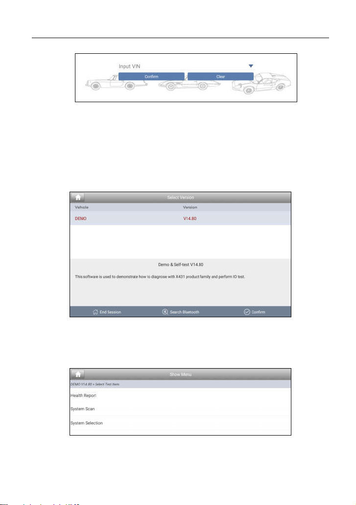
Tap “INPUT VIN” and a screen similar to Fig. 5-2 will appear:
Fig. 5-1
20
Page 30
LAUNCH X431 EURO TAB User Manual
(C) Diagtools & Launch Europe www.diagtools.lv, Riga, Pernavas 43A, LV-1009, t. +371 67704152, +371 29416069
Fig. 5-2
Input the VIN, and tap “Confirm” to enter the diagnostic software of the
vehicle.
2. Tap a corresponding diagnostic software logo, and then follow the
on-screen instruction to access the diagnostic software.
Take Demo as an example to demonstrate how to diagnose a vehicle.
1). Tap the “DEMO”, a screen similar to the following appears:
Fig. 5-3
2). Tap “Demo” to ignore Bluetooth connection and jump to the test item
selection screen. (Note: No Bluetooth connection is required for DEMO
program.)
Fig. 5-4
21
Page 31

LAUNCH X431 EURO TAB User Manual
(C) Diagtools & Launch Europe www.diagtools.lv, Riga, Pernavas 43A, LV-1009, t. +371 67704152, +371 29416069
5.1 Health Report (Quick Test)
This function varies from vehicle to vehicle. It enables you to quickly access all
the electronic control units of the vehicle and generate a detailed report about
vehicle health.
Tap “Health Report”, the system start scanning the ECUs. Once the scanning is
complete, a screen similar to the following appears:
Fig. 5-5
In Fig. 5-5, the tested system with fault code appears in red and the system with
OK displays in black (normally).
Tap the desired system to enter the test function selection page. For detailed
operations on test function, please refer to Chapter 5.3.
On-screen Buttons:
Clear DTC:
5.1.2.
Fault Report:
Tap to clear the existing diagnostic trouble codes. See Chapter
Tap to view the health report in details. See Chapter 5.1.1.
5.1.1 View fault report
This function allows you to view the health report in details.
22
Page 32

LAUNCH X431 EURO TAB User Manual
(C) Diagtools & Launch Europe www.diagtools.lv, Riga, Pernavas 43A, LV-1009, t. +371 67704152, +371 29416069
Fig. 5-6
In Fig. 5-6,
indicates the tested system with fault codes. Tap certain system to view the
1
detailed definitions of the DTCs. See Fig. 5-7.
stands for the total number of the tested systems.
2
indicates the total number of the fault codes existing in the tested system.
3
Fig. 5-7
On-screen Buttons:
Search:
Highlight a certain DTC item, and then tap it to launch the browser to
search for more detailed information about the selected DTC online.
To save the current data in text format.
Report:
“Diagnostic Report” in “My Report” from “Profile” menu. For details on report
operations, please refer to Chapter 13.1 “My Report”.
All reports are saved under the tab
23
Page 33

LAUNCH X431 EURO TAB User Manual
(C) Diagtools & Launch Europe www.diagtools.lv, Riga, Pernavas 43A, LV-1009, t. +371 67704152, +371 29416069
5.1.2 Clear DTC
This function lets you clear the existing diagnostic trouble codes in health report.
Tap “Clear DTC”, a confirmation dialog box appears. Tap “Yes” to clear all the
diagnostic trouble codes. Tap “No” to abort it.
5.2 System Scan
This option allows you to quickly scan which systems are installed on the
vehicle.
In Fig. 5-4, tap “System Scan”, the system start scanning the systems. Once the
scanning is complete, the screen will display the result. See Fig. 5-8.
Fig. 5-8
In Fig. 5-8, tap the desired system to advance to the test function selection page.
For detailed operations on test function, please refer to Chapter 5.3.
5.3 System Selection
This option allows you manually select the test system and function step by step.
In Fig. 5-4, tap “System Selection”, the screen displays as follows:
24
Page 34

LAUNCH X431 EURO TAB User Manual
(C) Diagtools & Launch Europe www.diagtools.lv, Riga, Pernavas 43A, LV-1009, t. +371 67704152, +371 29416069
Fig. 5-9
Swipe the screen from the bottom to view the vehicle system on the next page.
Tap the desired system (take “ECM” for example) to jump to the test function
page.
Fig. 5-10
Note: Different vehicle has different diagnostic menus.
5.3.1 Version Information
This function is used to read the version information of system mode, vehicle
VIN, software and ECU.
In Fig. 5-10, tap “Version Information”, the screen displays as Fig. 5-11.
25
Page 35

LAUNCH X431 EURO TAB User Manual
(C) Diagtools & Launch Europe www.diagtools.lv, Riga, Pernavas 43A, LV-1009, t. +371 67704152, +371 29416069
Fig. 5-11
Tap “OK” to confirm and exit.
5.3.2 Read Fault Code
This function displays the detailed information of DTC records retrieved from the
vehicle’s control system.
In Fig. 5-10, tap “Read DTC”, the screen will display the diagnostic result.
Fig. 5-12
On-screen Buttons:
Search:
Highlight a certain DTC item, and then tap it to search for more
information about the selected DTC online.
To save the current data in text format. All reports are saved under the
Report:
tab “Diagnostic Report” in “My Report” from “Profile” menu. For details on report
operations, please refer to Chapter 13.1 “My Report”.
Freeze Frame:
When an emission-related fault occurs, certain vehicle
conditions are recorded by the on-board computer. This information is referred
to as freeze frame data. Freeze frame data includes a snapshot of critical
parameter values at the time the DTC is set.
26
Page 36

LAUNCH X431 EURO TAB User Manual
(C) Diagtools & Launch Europe www.diagtools.lv, Riga, Pernavas 43A, LV-1009, t. +371 67704152, +371 29416069
5.3.3 Clear Fault Memory
After reading the retrieved codes from the vehicle and certain repairs have been
carried out, you can use this function to erase the codes from the vehicle. Before
performing this function, please be sure the vehicle’s ignition key is in the ON
position with the engine off.
In Fig. 5-10, tap “Clear Fault Memory”, a confirmation dialog box pops up on the
screen.
Tap “Yes”, the system will automatically delete the currently existing trouble
code.
The trouble code will not disappear until the trouble was completely cleared.
Note:
5.3.4 Read Data Stream
This option retrieves and displays live data and parameters from the vehicle’s
ECU.
In Fig. 5-10, tap “Read Data Stream”, the system will display data stream items.
Fig. 5-13
On-screen Buttons:
Select Page:
Tap it to select all items of the current page. To select certain data
stream item, just check the box before the item name.
Unselect:
Confirm:
Tap it to deselect all data stream items.
Tap it to confirm and jump to the next step.
After selecting the desired items, tap “Confirm” to enter the data stream reading
page.
27
Page 37

LAUNCH X431 EURO TAB User Manual
(C) Diagtools & Launch Europe www.diagtools.lv, Riga, Pernavas 43A, LV-1009, t. +371 67704152, +371 29416069
Fig. 5-14
Notes:
1. If the value of the data stream item is out of the range of the standard (reference)
value, the whole line will display in red. If it complies with the reference value, it
displays in black (normal mode).
2. The indicator 1/X shown on the bottom of the screen stands for the current
page/total page number. Swipe the screen from the right/left to advance/return to the
next/previous page.
On-screen Buttons:
After selecting, tap it to view the waveform. There are 3 types of display
Graph:
modes available for data viewing, allowing you to view various types of
parameters in the most suitable way.
Graph – displays the parameters in waveform graphs. Refer to Fig. 5-15.
28
Page 38

LAUNCH X431 EURO TAB User Manual
(C) Diagtools & Launch Europe www.diagtools.lv, Riga, Pernavas 43A, LV-1009, t. +371 67704152, +371 29416069
Fig. 5-15
Value – this is the default mode which displays the parameters in texts and
shows in list format.
Free Combine – this option is mostly used in graph merge status for data
comparison. In this case, different items are marked in different colors. See
Fig. 5-16.
Fig. 5-16
Record:
Tap to start recording diagnostic data for future playback and analysis.
The saved file follows the naming rule: It begins with vehicle type, and then the
record starting time and ends with .x431 (To differentiate between files, please
configure the accurate system time). The file is stored in “My Report” under
“Profile” menu. For details on playback operations, please refer to Chapter 13.1
“My Report”.
To stop reading the data stream, tap before the recording progress bar.
Save data:
Report:
Tap to save the current waveform as a diagnostic record.
Tap to access to “My reports”.
5.1.5 How to view diagnostic history?
Generally once a vehicle diagnosis is performed, X-431 EURO TAB will record
the every details of diagnostic process. The History function provides a quick
access to the tested vehicles and users can resume from the last operation,
without the necessity of starting from scratch.
1. Tap “History” tab on the diagnosis main menu screen, all diagnostic records
will be listed on the screen in date sequence.
Where the box with light blue background indicates that no DTCs are found
on this vehicle and the light yellow box indicates that the vehicle has DTCs.
29
Page 39

LAUNCH X431 EURO TAB User Manual
(C) Diagtools & Launch Europe www.diagtools.lv, Riga, Pernavas 43A, LV-1009, t. +371 67704152, +371 29416069
2. Tap a certain box to enter the history records.
3. Tap “Restore” to directly jump to the system selection screen.
4. Tap the desired system to enter and follow the instructions on the screen to
proceed.
5.2 Special (Reset) Function
In addition to amazing & powerful diagnostic function, X-431 EURO TAB also
features various service functions. The most commonly performed service
functions contain:
Oil Reset Service
Steering Angle Calibration
Electronic Parking Brake Reset
Battery Register / Battery Maintenance
ABS Bleeding
Electronic Throttle Position Reset / Learn
Diesel Particulate Filter (DPF) Regeneration
Tire Pressure Monitor System Reset
Oil Reset Service
This function can be performed in the following cases:
1. If the service lamp is on, you must provide service for the car. After service,
you need to reset the driving mileage or driving time so that the service lamp
turns off and the system enables the new service cycle.
2. After changing engine oil or electric appliances that monitor oil life, you need
to reset the service lamp.
Steering Angle Calibration
1. To reset the steering angle, first find the relative zero point position for the car
to drive in straight line. Taking this position as reference, the ECU can
calculate the accurate angle for left and right steering.
2. After replacing the steering angle position sensor, replacing steering
mechanical parts (such as steering gearbox, steering column, end tie rod,
steering knuckle), performing four-wheel alignment, or recovering car body,
you must reset the steering angle.
Electronic Parking Brake Reset
1. If the brake pad wears the brake pad sense line, the brake pad sense line
30
Page 40

LAUNCH X431 EURO TAB User Manual
(C) Diagtools & Launch Europe www.diagtools.lv, Riga, Pernavas 43A, LV-1009, t. +371 67704152, +371 29416069
sends a signal sense line to the on-board computer to replace the brake pad.
After replacing the brake pad, you must reset the brake pad. Otherwise, the
car alarms.
2. Reset must be performed in the following cases:
a) The brake pad and brake pad wear sensor are replaced.
b) The brake pad indicator lamp is on.
c) The brake pad sensor circuit is short, which is recovered.
d) The servo motor is replaced.
Electronic Throttle Position Reset/Learn
This function enables you to initialize the throttle actuators so that the “learned”
values stored on ECU are returned to the default state. Doing so can accurately
regulate throttle (or idle engine) operations to control the amount of air intake.
Throttle matching must be performed in the following cases:
a) The ECU is replaced and the ECU does not yet store throttle working
features.
b) The ECU is disconnected from power and the ECU memory is lost.
c) The throttle assembly is replaced.
d) The intake pipe is replaced or removed, which affects idle speed control by
ECU and throttle body.
e) The throttle is cleaned. Although the idle throttle potentiometer features
remain unchanged, with the same throttle opening, the air inflow has
changed and idle speed control features have changed.
Battery Register/Battery Maintenance
This function enables you to perform a resetting operation on the monitoring unit
of vehicle battery, in which the original low battery fault information will be
cleared and battery matching will be done.
Battery matching must be performed in the following cases:
a) Main battery is replaced. Battery matching must be performed to clear
original low battery information and prevent the related control module from
detecting false information. If the related control module detects false
information, it will invalidate some electric auxiliary functions, such as
automatic start & stop function, sunroof without one-key trigger function,
power window without automatic function.
b) Battery monitoring sensor. Battery matching is performed to re-match the
control module and motoring sensor to detect battery power usage more
accurately, which can avoid an error message displaying on the instrument
31
Page 41

LAUNCH X431 EURO TAB User Manual
(C) Diagtools & Launch Europe www.diagtools.lv, Riga, Pernavas 43A, LV-1009, t. +371 67704152, +371 29416069
panel.
ABS Bleeding
This function allows you to perform various bi-directional tests to check the
operating conditions of Anti-lock Braking System (ABS).
1. When the ABS contains air, the ABS bleeding function must be performed to
bleed the brake system to restore ABS brake sensitivity.
2. If the ABS computer, ABS pump, brake master cylinder, brake cylinder, brake
line, or brake fluid is replaced, the ABS bleeding function must be performed
to bleed the ABS.
Tire Pressure Monitor System Reset
1. After the tire pressure MIL turns on and maintenance is performed, the tire
pressure resetting function must be performed to reset tire pressure and turn
off the tire pressure MIL.
2. Tire pressure resetting must be performed after maintenance is performed in
the following cases: tire pressure is too low, tire leaks, tire pressure
monitoring device is replaced or installed, tire is replaced, tire pressure sensor
is damaged, and tire is replaced for the car with tire pressure monitoring
function.
Diesel Particulate Filter (DPF) Regeneration
DPF regeneration is used to clear PM (Particulate Matter) from the DPF filter
through continuous combustion oxidation mode (such as high temperature
heating combustion, fuel additive or catalyst reduce PM ignition combustion) to
stabilize the filter performance.
DPF regeneration may be performed in the following cases:
a) The exhaust back pressure sensor is replaced.
b) The PM trap is removed or replaced.
c) The fuel additive nozzle is removed or replaced.
d) The catalytic oxidizer is removed or replaced.
e) The DPF regeneration MIL is on and maintenance is performed.
f) The DPF regeneration control module is replaced.
32
Page 42

LAUNCH X431 EURO TAB User Manual
(C) Diagtools & Launch Europe www.diagtools.lv, Riga, Pernavas 43A, LV-1009, t. +371 67704152, +371 29416069
6 Software Update
If you did not download the software in process of product registration or a
pop-up message prompting you that some new software can be updated, you
may use this option to download it or keep it synchronized with the latest
version.
Tap “Software Upgrade” on the function menu to enter the update center.
Fig. 6-1
By default, all diagnostic software is selected. To deselect certain software, tap
“Unselect”, and then check the box next to vehicle model. Tap “Update” to start
downloading. It may take several minutes to finish it, please be patient to wait.
To pause downloading, tap “Stop”. To resume it, tap “Continue”. If network
connection failure occurs, tap “Retry” to try again.
Once download is finished, the software packages will be installed automatically.
33
Page 43

LAUNCH X431 EURO TAB User Manual
(C) Diagtools & Launch Europe www.diagtools.lv, Riga, Pernavas 43A, LV-1009, t. +371 67704152, +371 29416069
7 golo Business Manager
This module is an individual business management application specially
developed for repair shops. Before using it, you need to download the
application and register a golo business account.
On this platform, you can provide nearby car owners with attentive service to
develop new business opportunities, manage technicians and golo customers
more efficiently, monitor customer’s vehicle running status in real-time manner
and perform remote assistance anywhere etc. It is very helpful to increase
productivity and boost shop revenue.
Tap “golo” on the function menu to enter golo business manager account. See
Fig. 7-1.
Fig. 7-1
A. If you had no golo business manager account, tap “Join” to enter a screen
similar to Fig. 7-2:
34
Page 44

LAUNCH X431 EURO TAB User Manual
(C) Diagtools & Launch Europe www.diagtools.lv, Riga, Pernavas 43A, LV-1009, t. +371 67704152, +371 29416069
Fig. 7-2
Fill in the required items:
To upload the shop picture, tap the + logo to choose the desired photo.
To locate company address, tap the GPS location icon to obtain it
automatically.
To define the item “Model specialized”, tap the > icon to select the vehicle
models.
After entering, tap “Submit” to confirm. “Sign up successfully” will pop up and
the system will jump to golo main menu screen.
B. If you have a golo business manager account, tap “Link now” to bind this tool
to it.
Fig. 7-3
For more detailed operations on this module, please refer to the user manual
included within this application.
35
Page 45

LAUNCH X431 EURO TAB User Manual
(C) Diagtools & Launch Europe www.diagtools.lv, Riga, Pernavas 43A, LV-1009, t. +371 67704152, +371 29416069
8 Remote Diagnosis
This option aims to help repair shops or technicians launch instant messaging
and remote diagnosis, making the repair job getting fixed faster.
Tap “Remote Diagnosis” on the function menu, the screen appears blank by
default.
8.1 Interface Layout
Fig. 8-1
1 Exit button Tap it to navigate to the previous screen.
Directly input the username of the X-431 EURO TAB to
2 Search bar
3 Message tab
4 Contact tab Tap to enter the friend list.
start searching, and then tap the desired one to add it into
your friend list.
Once an incoming message reaches, a red dot will appear
on the upper right corner of the tab.
8.2 Add Friends
In the search bar, input the partner’s username and tap “Search” button next to
the search bar to starts searching from Launch’s golo business database.
The partner must be the users who have registered their Launch’s diagnostic
tools. They may be the following:
Workshop
Technician
golo users
Once the result matches the keyword, a screen similar to the following will
36
Page 46

LAUNCH X431 EURO TAB User Manual
(C) Diagtools & Launch Europe www.diagtools.lv, Riga, Pernavas 43A, LV-1009, t. +371 67704152, +371 29416069
appear:
Fig. 8-2
Tap “Add”, a dialog box pops up:
Fig. 8-3
Tap “CONFIRM” to send your request.
Once the partner receives the request, a beep will sound. Tap the “Message” tab,
tap “Agree” to confirm and his/her name will appear in the friend list.
8.3 Start Instant Messaging
Note: The I/M(Instant Messaging) function is open to all users who had Launch’s
diagnostic tool equipped with this module. But for remote diagnosis, it only can be
launched between two diagnostic tools that have the same product configurations.
After adding your friend, tap the desired friend’s logo to enter a screen similar to
the following:
37
Page 47

LAUNCH X431 EURO TAB User Manual
(C) Diagtools & Launch Europe www.diagtools.lv, Riga, Pernavas 43A, LV-1009, t. +371 67704152, +371 29416069
Fig. 8-4
Tap “Send Message” or tap the desired username directly from the friend list to
enter the instant messaging interface.
Tap the input field and use the on-screen keyboard to enter the text message,
and then tap “Send” to send it; tap to send the voice message; tap to
choose to send files, pictures etc.
8.4 Launch Remote Diagnosis
Note: Before performing this operation, please make sure the following no matter which
side sends the remote request:
Turn on the vehicle power supply.
Throttle should be in a closed position.
The VCI connector should be properly connected to the vehicle’s DLC and a
successful communication is required.
The same diagnostic software is installed on both sides.
Tap to display more options:
Fig. 8-5
Tap “Remote Diagnostic”, a pull-down menu including the following options
appears:
38
Page 48

LAUNCH X431 EURO TAB User Manual
(C) Diagtools & Launch Europe www.diagtools.lv, Riga, Pernavas 43A, LV-1009, t. +371 67704152, +371 29416069
Actions Results
Send remote
diagnostic reservation
Tap it and input the reservation title or scheduled date
of the remote diagnosis, and then tap “Confirm” to
send.
If you need support, just use this option to invite a
technician to perform a remote control on your tool.
Invite remote
diagnostic assistant
Request control
remote device
Request to control the partner’s device remotely to
help him diagnose the vehicle.
39
Page 49

LAUNCH X431 EURO TAB User Manual
(C) Diagtools & Launch Europe www.diagtools.lv, Riga, Pernavas 43A, LV-1009, t. +371 67704152, +371 29416069
Tap “Request control remote device”
Wait for partner’s confirmation
Start connecting after request confirmed
Start Diagnosis
Generate diagnostic report
Cancel To cancel this operation.
40
Page 50

LAUNCH X431 EURO TAB User Manual
(C) Diagtools & Launch Europe www.diagtools.lv, Riga, Pernavas 43A, LV-1009, t. +371 67704152, +371 29416069
9 Sensorbox (Toolbox)
9.1 Product Summary
X-431 EURO TAB provides an optional function of automotive sensor simulation
test. “Sensor” function is specially designed to diagnose and simulate vehicle
sensor faults quickly and conveniently, including “DC voltage simulation”, “Fixed
frequency simulation”, “Predefined waveform simulation” and “Hand-painted
waveform simulation”.
Vehicle sensors are the signal input devices for electrical control systems, which
can transform all kinds of running parameters, such as vehicle speed, coolant
temperature, engine RPM, air flow, throttle opening, etc., into the electronic
signal for the vehicle computer who can optimize the engine running status per
the above-mentioned parameters to keep the engine working in a prime status.
Meanwhile, it integrates the functions of automobile multimeter (For detailed
operations on multimeter, please refer to Chapter 10), which enables users to
perform voltage, resistance and frequency test. (The function utilizes the same
hardware device as the sensor module)
It features automotive sensor simulation test and multimeter test function.
Sensorbox
Parameters Scope
Precision ±5%
Voltage range -5V~+5V
Max output current 70mA
Predefined frequency range 0~150Hz
Square-wave signal pulse frequency 0~15KHz
Square-wave signal duty ratio 10%~90%
Multimeter
Parameters Scope
Precision ±5%
Voltage test Testing range DC-400V~+400V
41
Page 51

LAUNCH X431 EURO TAB User Manual
(C) Diagtools & Launch Europe www.diagtools.lv, Riga, Pernavas 43A, LV-1009, t. +371 67704152, +371 29416069
Input impedance 10Mohm
Resistance test Testing range 0~40Mohm
Testing range 0~25KHz
Frequency test
Input impedance 1000Gohm
Input voltage 1~12V
9.2 Structure & Accessories
9.2.1 Sensorbox structure
Fig. 9-1 Structural diagram of Sensorbox
Table 9-1 shows the ports and indicators for X-431 EURO TAB sensorbox
No. Name Description
1 Data receiving indicator
2 Data sending indicator
3 Power indicator
Indicator (green) for receiving data from main
unit.
Indicator (green) for sending data to main
unit.
It keeps steady on (red) after the sensorbox
is powered on.
4 Type-B USB port Connect to main unit with USB cable when it
42
Page 52

LAUNCH X431 EURO TAB User Manual
(C) Diagtools & Launch Europe www.diagtools.lv, Riga, Pernavas 43A, LV-1009, t. +371 67704152, +371 29416069
is applied as separated USB device.
5 Power connector
Connect to power supply through the power
adaptor.
6 COM Common terminal of multimeter
7 VΩHz Testing terminal of multimeter
9.2.2 Sensorbox accessories
The sensorbox accessories include sensor test cable, probe etc. See Table 9-2.
As the product configuration can be different, the accessories included with the
product may differ from the accessories listed on this manual. Please see the
packing list attached to the product for the detailed accessories.
Table 9-2 Accessory checklist
No.
1 Sensor test cable
2 Sensor probe
3 Multimeter probe
4 Electronic control converting
cable 1
Electronic control converting
5
cable 2
Electronic control converting
6
cable 3
Electronic control converting
7
cable 4
Name Picture
9.3 Sensor Simulation
9.3.1 Connections
1. Firstly, power the X-431 EURO TAB tablet on.
2. Plug one end of the sensor test cable (black) into the “COM” interface of the
43
Page 53

LAUNCH X431 EURO TAB User Manual
(C) Diagtools & Launch Europe www.diagtools.lv, Riga, Pernavas 43A, LV-1009, t. +371 67704152, +371 29416069
sensorbox, and then the other end to the test probe or electronic control
converting cable.
3. Connect one end of the sensor test cable (red) into the “VΩHz” interface of
the sensorbox, and then the other end to the test probe or electronic control
converting cable.
Note: Choose corresponding cables and test probes according to different terminals.
9.3.2 Simulation test
Simulation test enables users to exactly judge if the sensor is good or not to
avoid replacing components blindly. For example, the trouble code indicates the
fault is in water temperature sensor itself. But we need to confirm whether the
fault results from water temperature sensor or the connections between ECU
and sensors, or ECU itself. In this case, we can make full use of simulation test
to input the signal of simulating water temperature sensor, instead of water
temperature sensor, to the microcomputer. If the engine works better and the
fault vanishes, the fault is in the water temperature sensor. If the fault still occurs,
input the signal to the corresponding terminals of ECU. Consequently, if the fault
disappears, the fault lies in the connection between water temperature sensor
and ECU, otherwise, the fault exists in ECU.
After all connections are properly made (refer to Chapter 9.3.1 for details),
launch X-431 EURO TAB application and enter the function menu interface,
then tap “Toolbox” -> “Sensor” to enter the test selection screen. See Fig. 9-2.
Fig. 9-2
1. DC voltage simulation
In Fig. 9-2, tap [Current voltage], then tap “+” or “-” to adjust the output voltage
value. Alternatively, user can also tap edit box, then use the on-screen keyboard
44
Page 54

LAUNCH X431 EURO TAB User Manual
(C) Diagtools & Launch Europe www.diagtools.lv, Riga, Pernavas 43A, LV-1009, t. +371 67704152, +371 29416069
to input the desired value directly. After selecting or inputting the desired voltage
based on the working characteristics of sensor, tap the button, then the
X-431 EURO TAB will begin to output the simulation voltages. Please note the
red probe is the output terminal of simulation voltage.
2. Fixed frequency simulation
This option enables you to simulate the square wave signal of pulse frequency
of 0.1 ~ 15 kHz, amplitude range of -5V ~ +5V and duty cycle 10% ~ 90%.
In Fig. 9-2, tap “Fixed frequency simulation” to enter a screen similar to Fig. 9-3.
Fig. 9-3
Tap the setting option tab, then tap “+” or “-” to adjust the output. After setting,
tap to perform the test.
3. Predefined waveform simulation
X-431 EURO TAB provides some common sensor waveforms which have been
predefined to facilitate users to simulate sensor signals. As long as you call out
the predefined waveform, then tap to start simulating output of
corresponding sensor waveform and no more parameter settings of simulation
waveform are required.
In Fig. 9-3, tap “Predefined waveform simulation” to enter the screen shown as
Fig. 9-4.
45
Page 55

LAUNCH X431 EURO TAB User Manual
(C) Diagtools & Launch Europe www.diagtools.lv, Riga, Pernavas 43A, LV-1009, t. +371 67704152, +371 29416069
Fig. 9-4
Here, tap button, a screen similar to Fig. 9-5 will appear.
Fig. 9-5
In Fig. 9-5, the left setting column stands for sensor types and the right area
displays waveform. The sensor types are explained as below:
ECT: Coolant Temperature Sensor
EVP: EGR Valve Position Sensor
HO2S: Heated Oxygen Sensor
IAT: Intake Air Temperature Sensor
MAF: Mass Air Flow Sensor
MAP: Manifold Absolute Pressure Sensor
TP: Throttle Position Sensor
VAF: Volume Air Flow Sensor
VSS: Vehicle Speed Sensor
For example, tap “ECT” – “Warm (NTC Thermistor)” in Fig. 9-5, the right screen
46
Page 56

LAUNCH X431 EURO TAB User Manual
(C) Diagtools & Launch Europe www.diagtools.lv, Riga, Pernavas 43A, LV-1009, t. +371 67704152, +371 29416069
will display the waveform of the sensor.
Fig. 9-6
In Fig. 9-6, tap the waveform, then the pre-defined waveform has been set.
Fig. 9-7
In Fig. 9-7, tap button to perform simulation test.
4. Hand-painted waveform simulation
This option offers great convenience for users to simulate special waveform or
fault wave. Users only draw the shape of waveform which needs to be simulated
in central drawing area, and then configure some parameters on the top, namely
high level, low level, and cycle of waveform, then tap , X-431 EURO TAB will
output a waveform as desired.
Warning:
Just draw a complete periodic waveform (when it is output, the system
will regard the waveform in the drawing area as a periodic one). Users should draw as
large as wave in drawing zone so that the system can sample more points to reduce
47
Page 57

LAUNCH X431 EURO TAB User Manual
(C) Diagtools & Launch Europe www.diagtools.lv, Riga, Pernavas 43A, LV-1009, t. +371 67704152, +371 29416069
tolerance.
In Fig. 9-2, tap “Hand-painted waveform simulation”, a screen similar to Fig. 9-8
will appear.
Fig. 9-8
Button descriptions:
[ ]: Save the current waveform.
[ ]: Loads the previously saved hand-drawn waveform.
[ ]: Clear all hand-drawn waveform.
[ ]: Click to call out the predefined waveform for reference.
[ ]: Continues the following operation.
9.3.3 Precautions on checking vehicle sensor
Hold the connector when plugging or unplugging it. Do not pull the cable for
unplugging.
At first check the fuse, fusible line and terminals. Then check others after
eliminating these faults.
When measuring voltage, the ignition switch should be on and the battery
voltage should not be less than 11V.
When measuring voltage, please shake the lead lightly in the vertical and
horizontal direction for more precision.
When checking whether there is open in the line, disconnect the CEU and the
relevant sensor at first, then measure the resistance among the ports of
sensor in order to determine whether open-circuit / contact fault exists or not.
When checking if there is a short in the line, please disconnect the CEU and
the relevant sensor, then measure the resistance value of the ports between
48
Page 58

LAUNCH X431 EURO TAB User Manual
(C) Diagtools & Launch Europe www.diagtools.lv, Riga, Pernavas 43A, LV-1009, t. +371 67704152, +371 29416069
the connected port and the vehicle body. If the resistance value is more than
1MΩ, no fault occurs.
Before disassembling the engine electrical control system cable, cut off the
power supply, that is, turn the ignition switch OFF and disconnect the cables
on the battery poles.
Contact the test probe and the two terminals/ the two leads to be measured
when measuring the voltage between the two terminals or the two leads.
Contact the red test probe to the terminal/ the cable to be measured, and the
black probe to the ground when measuring voltage of one terminal/ one
cable.
When checking the continuity of the terminals, contacts and leads, the
method for measuring their resistances can be used.
Check the faults in the terminals of the CEU to sensors, relays, etc.
There are two test probes in the testing wire. The black one is the common
signal terminal (signal GND); the red one is the input terminal for voltage,
resistance, and frequency test and output terminal for simulation voltage,
simulation frequency and oxygen sensor. Please choose the correct probes
to match the different terminals.
49
Page 59

LAUNCH X431 EURO TAB User Manual
(C) Diagtools & Launch Europe www.diagtools.lv, Riga, Pernavas 43A, LV-1009, t. +371 67704152, +371 29416069
10 Multimeter (Toolbox)
10.1 Main Menu
Make sure the X-431 EURO TAB handset and the sensorbox are properly
connected (Refer to Chapter 9.3.1 Connections for details), launch X-431 EURO
TAB application, tap “Toolbox” -> “Multimeter” to display the test menu.
Fig. 10-1
Tap the desired test to perform related test.
The operation method on
that of
Voltage Test
Tap “Voltage Test”, a screen similar to Fig. 10-2 appears:
Resistance Test
. Here take Voltage test as an example for demonstration.
and
Frequency Test
is identical to
50
Page 60

LAUNCH X431 EURO TAB User Manual
(C) Diagtools & Launch Europe www.diagtools.lv, Riga, Pernavas 43A, LV-1009, t. +371 67704152, +371 29416069
Fig. 10-2
The following operations can be done:
[ ]: Erases the currently displayed waveform and display it starting from the
left.
[ ]: Reduces the range and zoom in the waveform.
[ ]: Increase the range and zoom out the waveform.
[ ]: Starts or stops the testing process.
10.2 Test Sample
Knock sensor testing
(1) Resistance test for knock sensor
Switch ignition “OFF”, unplug the wire connector of knock sensor, test the
resistance between the wire terminal and the case of knock sensor with
“Resistance test” function, it shall be ∞ (disconnected), and if it is
0Ω(conductive), which means the knock sensor shall be replaced. For the
magnetostriction knock sensor, it can also test the resistance by the “Resistance
measurement” function; the resistance shall be compliant with the specified
value (see specific service manual for the detailed data), otherwise, the knock
sensor shall be replaced.
(2) Checking for the output signal of knock sensor
Unplug the wire connector of knock sensor, check voltage between knock
sensor connector terminal and ground wire of knock, it should be output pulse
voltage; otherwise, the knock sensor shall be replaced.
Coolant temperature sensor testing
(1) Resistance test for coolant temperature sensor
On vehicle testing:
Switch ignition “OFF” and unplug the wire connector of coolant temperature
sensor, then use the “Resistance measurement” to test the Resistance between
two terminals of sensor. The relationship between the resistance and the
temperature is in inversely proportion (negative temperature coefficient), which
shall be less than 1kΩ during warming up.
Independent testing:
Unplug the wire connector of coolant temperature sensor, then remove the
sensor from the engine; place the sensor into a breaker with water and heat the
water, then use the “Resistance measurement” to test the Resistance between
two terminals of coolant temperature sensor at different water temperature.
51
Page 61

LAUNCH X431 EURO TAB User Manual
(C) Diagtools & Launch Europe www.diagtools.lv, Riga, Pernavas 43A, LV-1009, t. +371 67704152, +371 29416069
Compared the measured value with the standard value, if the Resistance is not
compliant with the standard, then the coolant temperature sensor shall be
replaced.
(2) Output signal voltage testing for coolant temperature sensor
After installing the coolant temperature sensor, plug the wire connector of
sensor, and then switch ignition ON, test the output signal voltage between the
two terminals of wire connector. The tested voltage shall be in inverse
proportional with the coolant temperature. When the harness of coolant
temperature sensor is disconnected, the voltage shall be about 5V if the ignition
switch is ON.
52
Page 62

LAUNCH X431 EURO TAB User Manual
(C) Diagtools & Launch Europe www.diagtools.lv, Riga, Pernavas 43A, LV-1009, t. +371 67704152, +371 29416069
11 Batterybox (Toolbox)
11.1 Product Summary
X-431 EURO TAB provides an optional function of automotive battery test,
which adopts the latest state-of-the-art conductance testing technology in the
world and can test vehicle’s battery status. Two testing environments (Inside the
Vehicle and Outside the Vehicle) are available and applicable to battery test. In
addition to battery test, charging system and actuation system test can be done
while Inside the Vehicle is selected.
It supports various battery standards and specifications, including CCA, DIN,
IEC, EN, JIS, SAE and GB etc. It is specifically designed to help car owner,
repair workshop, battery factory use battery test instrument properly and
determine whether the battery is normal or not.
Battery test aims to check starting plumbic acid storage batteries for vehicles,
ship, boats and aviations, etc. It can test all kinds of batteries complying with
CCA, DIN, JIS, EN, GB and SA standards. For detailed test standards, please
refer to Table 11-1.
Table 11-1 Test standard
Standards
CCA Battery Council International
DIN Deutsche Industry Normen
JIS Japanese Industry Standard
EN Europe Norm
IEC National Electrical Commission
GB Chinese National Standard
SAE Society of Automotive Engineers
Standard (Full name) Test capacity range
100~1700
100~1200
26A17~245H52
100~1700
100~1200
100~1200
100~1700
53
Page 63

LAUNCH X431 EURO TAB User Manual
(C) Diagtools & Launch Europe www.diagtools.lv, Riga, Pernavas 43A, LV-1009, t. +371 67704152, +371 29416069
11.2 Test Environment
11.2.1 Test environment
Inside the vehicle test indicates that the battery connects to loading devices,
such as engine, etc. After doing battery test, it can perform charging system and
actuation system test, which is proceeded as a whole simultaneously. Charging
system and actuation system test is not required but must not be performed
before battery test. Because it is difficult for vehicle technicians to judge where is
faulty exactly if they have the faintest idea of battery’s status itself.
Outside the vehicle test indicates that the battery is disconnected from all
loading devices on vehicles. Therefore, only battery test is supported in this
condition.
11.2.2 Battery status and description
There are mainly 5 states as follows:
No.
1 Good battery Indicates battery is normal.
2 Replace battery
3 Good-recharge Stands for low battery. The battery is good itself.
4 Charge-retest
5 Bad cell
States Descriptions
Indicates that battery is aged or becomes rejected, or
battery life cycle approaches to be exhausted. In this
case, battery voltage appears to be normal, but
battery itself is not well, i.e. battery polarity board has
been completely vulcanized or aged. Please replace
battery immediately.
It is better for a few batteries to be fully charged
before testing in order to avoid judging in error under
special conditions.
Indicates one of the battery cells is bad and cannot
work normally, but for which one is bad, it can’t be
verified. In this case, battery voltage is generally lower
than 11V, mainly resulting from internal circuitry
damage, such as short circuit, open circuit, dummy
weld etc.
54
Page 64

LAUNCH X431 EURO TAB User Manual
(C) Diagtools & Launch Europe www.diagtools.lv, Riga, Pernavas 43A, LV-1009, t. +371 67704152, +371 29416069
11.3 Batterybox Structure & Accessories
11.3.1 Batterybox structure
Fig.11-1 Batterybox structure diagram
Battery connector: Connect to vehicle’s battery for battery test.
1.
B type USB terminal: Connect to the X-431 EURO TAB tablet with a
2.
B-shaped USB cable.
11.3.2 Test accessories
Fig. 11-2 Kelvin clip
Fig. 11-3 A/B cable
11.4. Connections & Operations
11.4.1 Connection
Connect one end of the A/B cable to the B type USB terminal of the batterybox,
and then connect the other end to the USB port of X-431 EURO TAB tablet. This
connection applies to outside the vehicle test and inside the vehicle.
Notes:
1. Wait about 10 seconds and begin to communicate since the batterybox needs to
55
Page 65

LAUNCH X431 EURO TAB User Manual
(C) Diagtools & Launch Europe www.diagtools.lv, Riga, Pernavas 43A, LV-1009, t. +371 67704152, +371 29416069
initialize after connection is complete, otherwise, communication may fail.
2. Red lamp on the batterybox means it has been successfully powered up; If the green
light is always on, it indicates the clip is well connected; while the green light blinks,
it indicates that the clip has poor contact. Do not perform any test until the clip and
A/B cable are properly connected.
11.4.2 Inside the vehicle test
Battery test and charging system & actuation system test can be done in this
mode.
1. Battery test
Enter battery test main menu, and select a desired test environment as shown in
Fig. 11-4.
Fig. 11-4
Note: The sequences of inside the vehicle and outside the vehicle test are almost the
same, but under inside the vehicle condition, all loads in vehicles must be powered off
for getting an exact test value.
1. Firstly, the system detects whether floating electricity exists or not before
testing. If yes, turn on the headlamp to remove it. Otherwise, the system
starts test program directly.
2. Tap [Inside the vehicle], the system starts detecting floating electricity
automatically. If floating electricity is detected, it will prompt you to turn on the
headlamp.
3. Follow the on-screen instructions to turn on headlamp, the system starts
removing floating electricity.
4. Once the floating electricity is removed, a prompt message box “The floating
electricity has been removed, please turn off the headlamp to continue the
testing” will appear on the screen.
5. Follow the on-screen instructions to turn off the headlamp and tap [OK], the
56
Page 66

LAUNCH X431 EURO TAB User Manual
(C) Diagtools & Launch Europe www.diagtools.lv, Riga, Pernavas 43A, LV-1009, t. +371 67704152, +371 29416069
system will continue the testing. Tap , it will enter testing standard
selection screen.
Fig. 11-5
6. Select a testing standard except for JIS and tap , a screen similar to Fig.
11-6 will appear. Users can adjust capacity size by tapping on < or > or by
dragging the slider on the bar.
Fig. 11-6
If JIS is selected, tap , the system will enter Select testing capacity screen.
Users can select corresponding standard capacity value according to battery
model marked on battery.
7. Tap and the testing result will appear on the screen.
57
Page 67

LAUNCH X431 EURO TAB User Manual
(C) Diagtools & Launch Europe www.diagtools.lv, Riga, Pernavas 43A, LV-1009, t. +371 67704152, +371 29416069
Fig. 11-7
[ ]: Tap it to perform the charging system and starting system test.
[ ]: Tap to test it again.
[ ]: Tap it to reset the test.
2. Charging system and starting system test
While performing this test, the battery’s charging voltage value and starting
voltage can be obtained in case of engine starting and accelerating. Based on
the data, the system will judge whether battery’s charging and actuation status is
normal or not.
Tap in Fig. 11-7, a dialog box will pop up as Fig. 11-8.
Fig. 11-8
After detecting engine starting, follow the instructions on the screen to increase
the speed.
The system begins to receive test data information after acceleration was
detected, as shown in Fig. 11-9.
58
Page 68

LAUNCH X431 EURO TAB User Manual
(C) Diagtools & Launch Europe www.diagtools.lv, Riga, Pernavas 43A, LV-1009, t. +371 67704152, +371 29416069
Fig. 11-9
Tap [OK], test data will be shown on the screen.
Note: It is unnecessary to perform charging system and start system test after finishing
battery test, but battery test must be done before undergoing charging system and
starting system test.
11.4.3 Outside the vehicle test
It only applies to battery test and detecting floating electricity will be ignored
while performing battery test.
On Fig. 11-4, tap [Outside the vehicle] to select battery test standard.
The following operation steps are identical to Steps 6~7 in Chapter 11.4.2
Battery test. Please refer to it for details.
11.5 Precautions on Battery Test
For the purpose of getting accurate test results, unless otherwise special
required, all loads need to be power off such as headlamp, engine etc. before
testing battery.
The operating time required for charging system and actuation system test
varies from person to person. If the engine does not start or accelerate within 30
seconds, the system will prompt you “receiving timeout” and return to the initial
status.
Whether Engine is off or not has no influence on charging and actuation test
result after increased speed is detected, but other loads need to be powered off.
The accuracy of battery voltage, charging voltage, start voltage is 0.01V in test
results; CCA (Cold Cranking Amps) precision is 5CCA.
Generally, charging voltage value is greater than starting voltage.
Charging voltage range is as follows: 13.8--14.5V for domestic vehicle;
13.3--15.5V for imported vehicles. The voltage varies with different car models,
so you have to judge based on related vehicle models. In general, the DC
voltage is stable, but it also varies with different revolution speed.
Starting voltage range: The value higher than 9.6V is regular, otherwise it is too
low. Due to different situations, whether the starting voltage is higher or not does
not mean the vehicles or batteries are faulty. For detailed faults, other special
59
Page 69

LAUNCH X431 EURO TAB User Manual
(C) Diagtools & Launch Europe www.diagtools.lv, Riga, Pernavas 43A, LV-1009, t. +371 67704152, +371 29416069
equipments are needed. To validate the accuracy of the value, the best method
is to collect the signals of starting and charging voltage and observe it on an
oscillometer.
Generally, the voltage is lower than 11V for the bad cell battery, but it is possible
that the battery is completely exhausted or has a serious low capacity. In this
case, just recharge your battery. Bad cell always happens when the loads on a
stopping vehicle are turned on for a long time.
Please note that it is normal for quick detecting of “Increase speed” because it
follows the theory of detecting “Increase speed”: If the detected voltage is higher
than the previous battery test voltage, the system will prompt you a message of
“Engine has been speeded”
It has no influence on test result in the event that engine’s output voltage or
engine revolution is not very stable. No matter whether the vehicle is accelerated
or not, the output voltage only differs within 0.2V.
While doing inside the vehicle test, Kelvin clip is always found to be in poor
contact. To remain it in good contact, please shake it several times before
testing. Take down the battery connector, and test it again, the value probably
varies. The deviation may arise from battery connector.
Pay more attention to connect the clip. The battery poles connect with conductor,
which makes the clip has a poor connection when testing battery. A tolerance of
dozens of CCA occurs if the clip is out of position, or oil, dust attaches on the
pole. The gear and main body of clip should be fully matched with battery poles.
Notes:
1. Battery poles inside the vehicle are enveloped by connectors, which may produce
some errors for test results. The tolerance results from the resistance of connectors.
The greater the resistance value is, the greater the tolerance becomes. But generally,
the tolerance does not affect the test conclusion.
2. Testing the battery separately generates an exact test result. The battery box is a
very useful auxiliary tool for quick test. If any problems were found, test it
separately for getting an exact test result.
60
Page 70

LAUNCH X431 EURO TAB User Manual
(C) Diagtools & Launch Europe www.diagtools.lv, Riga, Pernavas 43A, LV-1009, t. +371 67704152, +371 29416069
12 Oscilloscope (Toolbox)
12.1 Introduction
The Scopebox is an optional add-on module of X-431 EURO TAB, including
automotive oscilloscope and automotive ignition waveform.
Automotive oscilloscope can make the auto repair technician quickly judge the
faults on automotive electronic equipment and wiring, and the oscilloscope
sweep speed is far greater than the signal frequency of such vehicles, usually
5-10 times of the measured signal. The automotive oscilloscope not only can
quickly acquire the circuit signal, but also can slowly display the waveform to
observe and analyze. It can also record and store the tested signal waveform
which can be recalled to observe for the fast signal, having great convenience to
failure analysis. Either high-speed signal (e.g.: Injection nozzle, intermittent fault
signal) or the slow-speed signal (e.g. the throttle position change and the oxygen
sensor signal) can be observed through automotive oscilloscope in an
appropriate waveform.
The electronic signal can be compared and judged via measuring five
parameters indexes. The five parameters are the amplitude (the maximum
voltage of signal), the frequency (the cycle time of signal), the shape (the
appearance of signal), the pulse width (the duty cycle or the time range of signal),
and the array (the repetition characteristic of signal), which can be tested,
displayed, saved by the automotive oscilloscope. Via the waveform analysis can
further detect the circuit fault on sensors, actuators, circuits, and electronic
control units, etc.
61
Page 71

LAUNCH X431 EURO TAB User Manual
(C) Diagtools & Launch Europe www.diagtools.lv, Riga, Pernavas 43A, LV-1009, t. +371 67704152, +371 29416069
12.2 Structure & Accessories
12.2.1 Scopebox structure
Fig 12-1 Scopebox Structure Diagram
Table 12-1 shows the ports and indicators for the Scopebox.
No.
1 Fixed signal generator
Name Description
Generate a square signal with fixed 1K
frequency.
2 CH1 Channel 1
3 CH2 Channel 2
4 CH3 Channel 3
5 CH4 Channel 4
6 External trigger External trigger signal
B-shaped USB
7
interface
8 Power interface
Communication
9
indicator
Connect main unit via USB cable as
separated individual USB devices.
Connect to power supply via the power
adapter.
It blinks in process of data communication.
10 Running indicator It remains steady green after the Scopebox
62
Page 72

LAUNCH X431 EURO TAB User Manual
(C) Diagtools & Launch Europe www.diagtools.lv, Riga, Pernavas 43A, LV-1009, t. +371 67704152, +371 29416069
is running.
11 Power indicator
It keeps steady red after the Scopebox is
powered on.
12.2.2 Scopebox accessories
The Scopebox includes the secondary pickup cable for 4-channel oscilloscope,
crocodile clips for 4-channel oscilloscope, etc. See Table 12-2.
As the product configuration can be different, the accessories included with the
product may differ from the accessories listed on this manual. Please see the
packing list attached to the product for the detailed accessories.
Table 12-2 Accessory checklist
No.
Secondary ignition pickup for
1
4-channel oscilloscope
Name Picture
Crocodile clips for 4-channel
2
oscilloscope
3 Direct ignition extension cable
6-way universal guide line for
4
4-channel oscilloscope
5 BNC to 4mm connector test cable
63
Page 73

LAUNCH X431 EURO TAB User Manual
(C) Diagtools & Launch Europe www.diagtools.lv, Riga, Pernavas 43A, LV-1009, t. +371 67704152, +371 29416069
Pin connector suite for 4-channel
6
oscilloscope
12.3 Connection & Initial Use
12.3.1 Connection
The Scopebox should work with the X-431 EURO TAB tablet.
1. Firstly, power on the X-431 EURO TAB tablet.
2. Then plug one end of ground cable of the Scopebox into external trigger
channel (GND), and the other end should be grounded.
3. Connect one end of probe cable to the CH1, CH2, CH3, or CH4 on the
Scopebox, and the other end to related signal terminal.
Warning: Please use the specific capacitance probe when diagnosing the ignition high
voltage line. Never connect the Scopebox to the ignition secondary circuit directly.
12.3.2 Initial interface introduction
Fig. 12-2 displays the initial interface of the Scopebox.
Fig. 12-2
64
Page 74

LAUNCH X431 EURO TAB User Manual
(C) Diagtools & Launch Europe www.diagtools.lv, Riga, Pernavas 43A, LV-1009, t. +371 67704152, +371 29416069
No.
Descriptions
1 Signal display area
2 Horizontal Settings: Controls the time base.
3 Vertical Settings: Controls the amplitude of the displayed signal.
4 Trigger Settings: Controls the start event of the sweep.
5 Channel Selection Button
6 Function Menu
[Auto]: It indicates auto trigger setting.
[Ref]: There are expert reference and base reference available.
Expert reference enables you to recall your customized expert
database, whereas base reference provides automatic pre-setting
function of specialized sensors.
[File]: Provides save snapshot, snapshot manager, waveform
record and waveform replay.
[View]: Calibration and display settings are available.
[Measure]: Includes signal source measurement, horizontal
measurement, vertical measurement and clear measurement.
[Settings]: Shows/hides the parameter settings area including
horizontal settings, vertical settings and trigger settings.
/ [Start/Stop]: Starts/stops collecting waveforms.
12.4 Operations
12.4.1 Channel selection and attributes setting
<1> Channel selection
There are two ways available for channel selection:
A. Select from the channel tab shown at the bottom of the waveform display area
B. Select from Vertical settings
Note: For better comparison and identification, each channel and waveform are marked
in different colors.
65
Page 75

LAUNCH X431 EURO TAB User Manual
(C) Diagtools & Launch Europe www.diagtools.lv, Riga, Pernavas 43A, LV-1009, t. +371 67704152, +371 29416069
Fig. 12-3
<2> Channel attributes & trigger setting
Channel attributes can be set via horizontal settings and vertical settings.
Horizontal Settings
User can make some settings directly by tapping < or > next to options.
Options descriptions:
Fig. 12-4
Menu Comments/Settings
Horizontal scale. If the waveform acquisition is stopped
Time/DIV
(using the / button), the Time/DIV selector expands
or compresses the waveform.
The conventional oscilloscope display format. It shows the
Y-T format
voltage of a waveform record (on the vertical axis) as it
varies over time (on the horizontal axis).
Vertical Settings
The trigger determines when the Scopebox starts to acquire data and display a
waveform. When a trigger is set up properly, it can convert unstable displays or
blank screens into meaningful waveforms.
66
Page 76

LAUNCH X431 EURO TAB User Manual
(C) Diagtools & Launch Europe www.diagtools.lv, Riga, Pernavas 43A, LV-1009, t. +371 67704152, +371 29416069
When the Scopebox starts to acquire a waveform, it collects enough data so that
it can draw the waveform to the left of the trigger point. The Scopebox continues
to acquire data while waiting for the trigger condition to occur. After it detects a
trigger, the Scopebox continues to acquire enough data so that it can draw the
waveform to the right of the trigger point.
User can make some settings directly by tapping < or > next to options.
Options descriptions:
Fig. 12-5
Menu Comments/Settings
Channel To select the channel source.
Volts/DIV
It is defined as “Volts/Division” and mainly used to
change the resolution.
Trigger coupling determines what part of the signal
passes to the trigger circuit. AC, DC and Ground are
included:
Coupling
AC: Blocks the DC component of the input signal.
DC: Passes both AC and DC components of the input
signal.
Ground: Disconnects the input signal.
When using a probe, the Scopebox allows you to select
the attenuation factor for the probe. The attenuation
Probe
factor changes the vertical scaling of the Scopebox so
that the measurement results reflect the actual voltage
levels at the probe tip.
ON: Limits the channel bandwidth to 20MHz to reduce
BW Limit
display noise.
OFF: Get full bandwidth.
67
Page 77

LAUNCH X431 EURO TAB User Manual
(C) Diagtools & Launch Europe www.diagtools.lv, Riga, Pernavas 43A, LV-1009, t. +371 67704152, +371 29416069
Invert
ON: Turn on the invert function.
OFF: Restore to the original display of the waveform.
Trigger setting
Trigger indicates that when certain waveform meets the conditions that are
predefined according to the requirements, the Scopebox acquires the waveform
and its adjacent section, and then presents it on the screen.
Fig. 12-6
1) If Edge trigger is selected (An edge trigger determines whether the Scopebox
finds the trigger point on the rising or the falling edge of a signal.):
Menu Comments/Settings
The sweep mode determines how the Scopebox behaves
in the absence of a trigger event. The Scopebox provides
three trigger modes: Auto, Normal, and Single.
Auto: It allows the Scopebox to acquire waveforms even
when it does not detect a trigger condition. If no trigger
condition occurs while the Scopebox is waiting for a
specific period, it will force itself to trigger.
When forcing invalid triggers, the Scopebox can not
Sweep
synchronize the waveform, and then waveform seems to
roll across the display. If valid triggers occur, the display
becomes stable on the screen.
Normal: This mode allows the Scopebox to acquire a
waveform only when it is triggered. If no trigger occurs,
the Scopebox keeps waiting, and the previous waveform,
if any, will remain on the display.
Single: In this mode, it only acquires the waveform that
generates for the first time the trigger conditions are met,
68
Page 78

LAUNCH X431 EURO TAB User Manual
(C) Diagtools & Launch Europe www.diagtools.lv, Riga, Pernavas 43A, LV-1009, t. +371 67704152, +371 29416069
and then stops after finishing capture.
Source Select which channel as trigger signal.
Slope
High Freq
+ : Trigger on rising edge
- : Trigger on falling edge
Reject high frequency signals when selected.
Rejection
2) If Pulse Width trigger is selected (Pulse trigger occurs according to the width
of pulse. The abnormal signals can be detected through setting up the pulse
width condition):
Menu Comments/Settings
The sweep mode determines how the Scopebox
behaves in the absence of a trigger event. The Scopebox
provides three trigger modes: Auto, Normal, and Single.
Auto: It allows the Scopebox to acquire waveforms even
when it does not detect a trigger condition. If no trigger
condition occurs while the Scopebox is waiting for a
specific period, it will force itself to trigger.
When forcing invalid triggers, the Scopebox can not
Sweep
synchronize the waveform, and then waveform seems to
roll across the display. If valid triggers occur, the display
becomes stable on the screen.
Normal: This mode allows the Scopebox to acquire a
waveform only when it is triggered. If no trigger occurs,
the Scopebox keeps waiting, and the previous waveform,
if any, will remain on the display.
Single: In this mode, it only acquires the waveform that
generates for the first time the trigger conditions are met,
and then stops after finishing capture.
Source Select which channel as trigger signal.
Condition To select pulse condition.
Pulse Width Set required pulse width.
High Freq
Reject high frequency signals when selected.
Rejection
69
Page 79

LAUNCH X431 EURO TAB User Manual
(C) Diagtools & Launch Europe www.diagtools.lv, Riga, Pernavas 43A, LV-1009, t. +371 67704152, +371 29416069
12.4.2 Auto
The Scopebox has an Auto feature that sets up the Scopebox automatically to
display the input signal in a best fit.
Tap , the Scopebox may change the current settings to display the signal. It
automatically adjusts the vertical and horizontal scaling, as well as the trigger
coupling, position, slope, level and mode settings.
12.4.3 View Settings
<1> Calibration
This option adjusts the Scopebox’s internal circuitry to get the best accuracy.
Use this function to calibrate the Scopebox’s vertical and horizontal systems.
Tap and then tap [Calibration], a dialog box similar to Fig. 12-7 will appear.
Fig. 12-7
Check the box before the channel to select it. To deselect it, just uncheck it. After
choosing the desired channel(s), tap [Start] to start calibration and [Start] button
will be temporarily invalid during calibrating. Tap [Stop] to stop calibrating. Once
it becomes active, it indicates calibration has completed.
Note: In process of calibration, make sure CH1/CH2/CH3/CH4 has no signal input.
Moreover, calibration may take several minutes and please be patient to wait.
<2> REF settings
Reference waveforms are saved waveforms to be selected for display. The
reference function will be available after saving the selected waveform to
70
Page 80

LAUNCH X431 EURO TAB User Manual
(C) Diagtools & Launch Europe www.diagtools.lv, Riga, Pernavas 43A, LV-1009, t. +371 67704152, +371 29416069
non-volatile memory.
Tap and then [REF] to enter the REF setting screen.
Fig. 12-8
Tap < or > to select the desired reference value for time/DIV and volts/DIV. To
show or hide the REF, just check/uncheck the box before On/Off.
<3> Display settings
Tap and then [Display settings] to enter the setting screen.
Fig. 12-9
Select “Vectors” or “Dots” to display waveforms as vectors or dots. Check /
uncheck the box before Grid to turn on/off grid display.
12.4.4 Measure
<1> Channel source
Tap and then [Source], a screen similar to Fig. 12-10 will appear.
71
Page 81

LAUNCH X431 EURO TAB User Manual
(C) Diagtools & Launch Europe www.diagtools.lv, Riga, Pernavas 43A, LV-1009, t. +371 67704152, +371 29416069
Fig. 12-10
<2> Horizontal / Vertical measure
Horizontal Measure / Vertical Measure are used to measure voltage parameter
and time parameter respectively. Drag A line upwards or downwards to control
voltage. Move A line left or right to fine-tune timebase. A line is a solid line and B
line is a dotted line.
Tap and then [Horizontal Measure], a screen similar to Fig. 12-11 will
appear.
Fig. 12-11
Note: If no desired channel is selected, the system will take the current source as the
default channel.
<3> Clear measure
Tap and then [Clear Measure], the system will clear the measurement result
on screen.
72
Page 82

LAUNCH X431 EURO TAB User Manual
(C) Diagtools & Launch Europe www.diagtools.lv, Riga, Pernavas 43A, LV-1009, t. +371 67704152, +371 29416069
12.4.5 File management
<1> Save snapshot
While viewing sampling data, tap and then [Save Snapshot] to store the
current screen.
<2> Snapshot manager
While viewing sampling data, tap and then [Snapshot Manager] to enter.
View, delete and edit operations are supported.
<3> Record waveform
This function is used to record input waveforms that are acquired by the
Scopebox at a specific period, and save it as waveform file which can be
recalled in future.
It can be performed only when the Scopebox is collecting data in Normal mode.
Tap , then select [Record] from the pop-up menu to start recording.
Fig. 12-12
Tap [Start] to start recording with a minimum record length of 10 frames, and
[Stop] to stop recording. While recording, the recorded pages will be shown on
the screen.
<4> Load waveform for playback
The Import function enables you to import the stored waveform file for playback
and review. During replaying, the Scopebox stops collecting data automatically.
Tap , then select [Waveform replay] from the pop-up menu to enter:
73
Page 83

LAUNCH X431 EURO TAB User Manual
(C) Diagtools & Launch Europe www.diagtools.lv, Riga, Pernavas 43A, LV-1009, t. +371 67704152, +371 29416069
Fig. 12-13
Select the file first, and then tap to open the waveform file. Tap to
starting the playback and tap to stop it.
Fig. 12-14
To delete the waveform file, tap .
Tap to return to the previous screen.
12.4.6 Expert reference
<1> Expert Reference
By default, it appears blank. As a matter of fact, Expert reference database is
generated by doing the following:
1. Open and edit a snapshot.
2. Select “Joint the expert database” (refer to the following illustration), and then
tap to save the waveform being displayed on the screen as REF.
74
Page 84

LAUNCH X431 EURO TAB User Manual
(C) Diagtools & Launch Europe www.diagtools.lv, Riga, Pernavas 43A, LV-1009, t. +371 67704152, +371 29416069
Fig. 12-15
Tap and then [Expert Reference] to enter, the following operation can be
done:
: To load and recall the selected file.
: To delete the selected file.
: To edit the selected file.
<2> Base Reference
Preset waveforms of some sensors are available for your reference.
Fig. 12-16
75
Page 85

LAUNCH X431 EURO TAB User Manual
(C) Diagtools & Launch Europe www.diagtools.lv, Riga, Pernavas 43A, LV-1009, t. +371 67704152, +371 29416069
13 My Data
This function allows users to manage personal information and VCI connector.
13.1 My Report
This option is used to view, delete or share the saved reports.
Tap “
My Report
In case the DTC result is saved on Read Trouble Code page, the files will be
listed under
If user records the running parameters while reading data stream, it will be
saved as .x431 file and appear under
Tap the desired one to enter, a screen similar to the following displays:
Select the desired data stream items and tap “Submit” to jump to the playback
page.
”, there are total 3 options available.
Diagnostic Report
tab.
Diagnostic Record
Fig. 13-1
tab.
76
Page 86

LAUNCH X431 EURO TAB User Manual
(C) Diagtools & Launch Europe www.diagtools.lv, Riga, Pernavas 43A, LV-1009, t. +371 67704152, +371 29416069
Fig. 13-2
On-screen Buttons:
– displays the parameters in waveform graphs.
Graph
– this is the default mode which displays the parameters in texts and
Value
shows in list format.
Combine
In this case, different items are marked in different colors.
Frame Playback
Once it is in frame playback mode, this button changes into “Auto Playback”.
Remote Diagnostic Report
remote diagnosis.
– this option is mostly used in graph merge status for data comparison.
– plays back the recorded data stream items frame by frame.
lists all diagnostic reports generated in process of
13.2 My Connector
This option allows you to manage all your activated VCI connectors.
If several VCI connectors are activated on this tool, a list of connectors will be
displayed on the screen. Once you choose the connector that belongs to other
account, you have to log out, and then input the right account to continue.
13.3 Diagnostic connector connection management
This option is used for X-431 EURO TAB to deactivate pairing up with the VCI
connector via Bluetooth.
* Note: please be sure to keep the VCI connector powered on while performing the
operation.
77
Page 87

LAUNCH X431 EURO TAB User Manual
(C) Diagtools & Launch Europe www.diagtools.lv, Riga, Pernavas 43A, LV-1009, t. +371 67704152, +371 29416069
13.4 Activate Connector
This item lets you to activate a new VCI connector.
Product SN
Product SN
Activation code
Fig. 13-3
Input the Serial Number and Activation Code, and then tap “Activate” to activate
the connector.
For details on how to obtain Activation Code, tap the link below to get help.
13.5 Firmware Fix
Use this item to upgrade and fix diagnostic firmware. During fixing, please do not
cut power or switch to other interfaces.
13.6 Profile
Use this item to view and configure personal information.
13.7 Change password
This item allows you to modify your login password.
78
Page 88

LAUNCH X431 EURO TAB User Manual
(C) Diagtools & Launch Europe www.diagtools.lv, Riga, Pernavas 43A, LV-1009, t. +371 67704152, +371 29416069
14 Settings
It enables you to make some application settings and view software version
information etc.
14.1 Units of Measurement
It is designed to configure the measurement unit. Metric System and English
System are available.
14.2 Print Information
This option lets you define your print information. It mainly includes Workshop,
Address, Telephone, Fax and License Plate. After inputting, tap “Save”.
14.3 Launch Printer Connection
This option is designed to establish a wireless connection between X-431 EURO
TAB and the Wi-Fi printer (sold separately) while performing printing operations.
Follow the steps below to connect the printer.
1. Tap “Printer Connection”.
Fig. 14-1
A. If it is the first time you have operated this printer, please proceed the
following:
2. For initial use, you are suggested to reset the printer: Press and hold [MODE]
79
Page 89

LAUNCH X431 EURO TAB User Manual
(C) Diagtools & Launch Europe www.diagtools.lv, Riga, Pernavas 43A, LV-1009, t. +371 67704152, +371 29416069
& [FEED] for 8 seconds, the following resetting command will be printed out:
at + default = 1
ok
at + reboot = 1
rebooting...
3. Tap “Reset” to configure Wi-Fi printer.
Step 1: Connect the printer:
Tap “Scan” to select the desired printer hotspot named with
X-431PRINTER-XXXX (XXXX stands for 4 characters), and then tap
“Connect” to enter Step 2.
Fig. 14-2
Step 2: Join the Wi-Fi printer into LAN:
Tap “Scan” to select the desired local Wi-Fi network from the list, and type in
the security password (If it is an open network, password is not required), and
then tap “Confirm”.
80
Page 90

LAUNCH X431 EURO TAB User Manual
(C) Diagtools & Launch Europe www.diagtools.lv, Riga, Pernavas 43A, LV-1009, t. +371 67704152, +371 29416069
Fig. 14-3
4. Once the Wi-Fi network of the printer is connected and the printer is found,
tap “Printing test” to test the printing.
Fig. 14-4
Now you can use the Wi-Fi printer to print!
If the printer is not found, please reset the printer to default factory settings (refer
to Step 2 for details) and check whether the current device and the printer are on
the same LAN.
B. If you have configured the Wi-Fi printer to the LAN:
2. Tap “Connect to Printer”:
a). If the local network remains as it is, tap “Test Print” directly to test the
81
Page 91

LAUNCH X431 EURO TAB User Manual
(C) Diagtools & Launch Europe www.diagtools.lv, Riga, Pernavas 43A, LV-1009, t. +371 67704152, +371 29416069
printing.
b). If the local network changes, you have to reset the Wi-Fi printer.
14.4 Network test
It enables you to test whether the current network environment is good or not. It
is normal that you may encounter a logout while testing.
14.5 About
The software version information and disclaimer are included.
14.6 Log Out
To logout the current user ID, tap “Exit from current account”.
82
Page 92

LAUNCH X431 EURO TAB User Manual
(C) Diagtools & Launch Europe www.diagtools.lv, Riga, Pernavas 43A, LV-1009, t. +371 67704152, +371 29416069
15 Wi-Fi Printer
This Wi-Fi printer is an optional accessory of X-431 EURO TAB. The built-in
Wi-Fi module enables you to easily print the real time test results without
connecting any USB cable.
Compared to conventional printers, it is smaller and easier to carry. Meanwhile,
being free of paper spindle, it is also simple and fast to load printing paper. In
addition to the included DC power adaptor, it can be powered alternatively by
the built-in rechargeable battery, which enables you to use it anytime and
anywhere.
Furthermore, this printer has auto-hibernate and auto power-off features. While
it does not perform printing operation, it will enter auto sleeping mode to save
power. If no activities are made within 30 minutes, it will power off automatically.
To start printing, users need to power it on again.
15.1 General controls
Fig. 15-1
1 Side lock notch
83
Page 93

LAUNCH X431 EURO TAB User Manual
(C) Diagtools & Launch Europe www.diagtools.lv, Riga, Pernavas 43A, LV-1009, t. +371 67704152, +371 29416069
2 Paper outlet
3 POWER button Press and hold it for 2 seconds to turn it on/off.
MODE (ready)
4
button
FEED (paper test)
5
button
Press it to get the printer ready or switch it to
manual feed mode.
Press it to test whether thermal paper is
properly installed while the MODE indicator
goes out.
[Green]: Indicates the battery is fully
6 CHARGE indicator
charged.
[Red]: Indicates it is charging.
DC 9V adaptor
7
jack
*Note: The USB port next to it is disabled. Do not
attempt to insert the cable into it.
Rechargeable
8
battery
15.2 Thermal paper loading
This Wi-Fi printer applies thermal paper roll with size of Φ30×57mm. Follow the
steps described as below to load it.
1. Hold the side notches on the front of the printer and lift it up to open the cover.
Fig. 15-2
2. Place the unpacked thermal paper into the compartment with its starting end
approaching to the paper outlet (refer to the figure shown as below).
Reversing paper direction will result in that no results will be printed out.
84
Page 94

LAUNCH X431 EURO TAB User Manual
(C) Diagtools & Launch Europe www.diagtools.lv, Riga, Pernavas 43A, LV-1009, t. +371 67704152, +371 29416069
Fig. 15-3
3. Pull out some printing paper and introduce it along the slot until it comes out of
the paper outlet shown as below. Otherwise, paper cannot be fed.
Fig. 15-4
4. Close the paper cover and press it down until you hear a click (see the figure
shown on the next page).
Fig. 15-5
Notes:
A. After loading the paper, users need to check whether the paper can be fed normally.
For details, please refer to “How to print test results”.
B. If the printer keeps printing for a long time, the thermal matrixes (shown as below)
will overheat. To avoid a risk of burning injury, please do NOT touch the matrixes.
85
Page 95

LAUNCH X431 EURO TAB User Manual
(C) Diagtools & Launch Europe www.diagtools.lv, Riga, Pernavas 43A, LV-1009, t. +371 67704152, +371 29416069
Fig. 15-6
The printer applies the thermal paper, which should be prevented from being
*Note:
heated before printing, otherwise, the paper would be no longer effective or printing
result disappears.
15.3 Using the rechargeable battery
The included rechargeable battery must be installed to ensure that the printer
can print the test result normally. This printer utilizes a 7.2V, 1200mAh
rechargeable Lithium battery. Do the following steps to install and charge it:
1. Align the latches on the bottom of the battery with the holes on the battery
compartment.
Fig. 15-7
2. Press the battery down until it is firmly fitted.
3. Press the [POWER] button for 2 seconds to turn it on. If the battery is low, the
[POWER] indicator blinks. In this case plug the included adaptor into an outlet
to charge it in time. While charging, the charge indicator turns red. After
charging is complete, the indicator will turn green. The normal charging time is
2 hours.
Notes:
A. Please use the included DC adaptor and rechargeable battery only. We assume no
86
Page 96

LAUNCH X431 EURO TAB User Manual
(C) Diagtools & Launch Europe www.diagtools.lv, Riga, Pernavas 43A, LV-1009, t. +371 67704152, +371 29416069
responsibilities for any personal injury or loss resulting from using other adaptors
or rechargeable batteries not specified in this user manual.
B. If the printer keeps unattended for a long period, please remove the rechargeable
battery.
15.4 Printer connection
The printer can work as a Wi-Fi peer-to-peer printer or a Wi-Fi hotspot printer.
A. While used as a Wi-Fi peer-to-peer (P2P) printer, follow the steps described
below to make Wi-Fi connection:
Note: This mode configures the printer as auxiliary equipment and only works with
X-431 EURO TAB. In this case, the X-431 EURO TAB cannot surf the Internet.
1. Tap “Settings” on the home screen.
2. Tap “Wi-Fi” and slide its switch to ON.
Fig. 15-8
3. Locate and tap the X-431PRINTER-XXX (XXX stands for 3 numbers).
4. Input the identity password (default factory value is 12345678) and tap
“Connect”. “Connected” will appear on the screen once it is successful.
B. If used as a Wi-Fi hotspot printer, refer to Chapter 14.3 “Printer connection” to
make Wi-Fi connection and settings.
*Note: This mode only applies to WLAN environment and works with Android-based
diagnostic tools manufactured by LAUNCH. Other Android-based devices equipped
with this app only can perform the functions of printer configuration and printing test.
15.5 How to print test results?
There are three indicators on the printer:
*
[POWER]
: Power indicator
87
Page 97

LAUNCH X431 EURO TAB User Manual
(C) Diagtools & Launch Europe www.diagtools.lv, Riga, Pernavas 43A, LV-1009, t. +371 67704152, +371 29416069
[Red]: Indicates that the printer is on.
[Red & blink]: Indicates that the battery is low.
[Off]: Indicates the printer is off.
*
[MODE]:
[Green]: Indicates that the printer is ready.
[Green & blink]: Indicates that no thermal paper is loaded or the printer runs
out of paper.
[Off]: Indicates that the printer is switched to manual feed mode.
*
[FEED]:
Ready indicator
Paper test indicator
[Green]: Indicates that users can press the [FEED] button to check whether
the paper is fed normally.
[Off]: Indicates that manual mode is off.
Press the [POWER] button for 2 seconds to turn it on, the [MODE] indicator
blinks and then remains on (Every time you load or change the paper, press the
[MODE] button to turn the indicator off first, and then press [FEED] to test
whether the paper can be fed properly). When the [MODE] indicator is on, it
shows that the printer is ready.
If a printer button appears on the bottom of the screen, it means that printing
operation can be done. Tap it to start printing.
88
Page 98

LAUNCH X431 EURO TAB User Manual
(C) Diagtools & Launch Europe www.diagtools.lv, Riga, Pernavas 43A, LV-1009, t. +371 67704152, +371 29416069
16 Others
16.1 Email
The function allows you to send and receive email.
16.1.1 Configure an email account
Note: Before sending or receiving email, you have to set up an email account. In
addition, this function required a stable network connection.
1. On the home screen, tap Email.
2. Choose the desired email account type.
3. Input email address and password, tap “Next”.
Note: If “Manual setup” is selected, please consult your email service provider for
detailed parameter setting.
4. Follow the on-screen instructions to proceed until the system prompts you
that the account setup has been finished.
16.1.2 Add an email account
1. Tap Settings -> Accounts.
2. Tap Add account.
3. Choose the desired account type.
16.2 Browser
16.2.1 Open browser
On the home screen, tap Browser to launch the browser. You can choose the
desired homepage or input the website address to browse.
Fig. 16-1
1 Return to the previous page.
89
Page 99

LAUNCH X431 EURO TAB User Manual
(C) Diagtools & Launch Europe www.diagtools.lv, Riga, Pernavas 43A, LV-1009, t. +371 67704152, +371 29416069
2 Advance to the recently visited page.
3 Refresh the current page.
4 Close the current page.
5 Create a new tab.
6 Input a web address.
7 Add the current page as bookmark.
8 Open search bar.
9 Open bookmark list.
10 View more options.
16.2.2 Download files
Files, pictures, and applications can be downloaded from the website in browser.
For example:
Tap and hold a picture, then choose “Save image” from pop-up menu to
download it.
To download a link, tap and hold it, and then choose “Save link”.
To protect your X-431 EURO TAB and personal data, please download
applications from trusted sources. To configure it, tap Settings -> Security, and
then slide the Unknown sources switch to off.
16.3 Synchronization
You can transfer media files and APK between the PC and X-431 EURO TAB.
16.3.1 Connect to PC
1. Use the USB cable to connect the X-431 EURO TAB to your PC.
2. Swipe from the top, a message “Connected as a media device” appears.
16.3.2 Run on PC
Perform the following steps:
Locate the new disc.
Copy the files.
90
Page 100

LAUNCH X431 EURO TAB User Manual
(C) Diagtools & Launch Europe www.diagtools.lv, Riga, Pernavas 43A, LV-1009, t. +371 67704152, +371 29416069
16.3.3 Install an application
Do the following steps:
1. Tap Settings -> Security, and set the “Unknown sources” to ON, which
allows you to install apps from unknown sources.
2. A dialog box appears on the screen, tap “OK” to confirm.
3. Set the tool as “Connected as a media device”, and copy the APK file from
the PC to the tool.
16.4 Clear Cache
Doing so clears all browsing records and accounts and enables X-431 EURO
TAB to run smoothly and quickly.
1. Tap Settings -> Apps.
2. Tap and select “Sort by size” to arrange all applications in size order.
3. Tap certain application, then tap “Clear Cache” to release the space these
cache files are occupied.
91
 Loading...