

Page 1

FCC ID: XUJS3001
Heavy duty / Medium duty / Light duty Vehicle Communication Interface
S3001
LAUNCH
Launch Tech Co., Ltd.
Page 2

LAUNCH
S3001 User Manual
Copyright Information
Copyright © 2018 by LAUNCH TECH. CO., LTD. All rights reserved. No part of
this publication may be reproduced, stored in a retrieval system, or transmitted
in any form or by any means, electronic, mechanical, photocopying, recording or
otherwise, without the prior written permission of LAUNCH. The information
contained herein is designed only for the use of this unit. LAUNCH is not
responsible for any use of this information as applied to other units.
Neither LAUNCH nor its affiliates shall be liable to the purchaser of this unit or
third parties for damages, losses, costs, or expenses incurred by purchaser or
third parties as a result of: Accident, misuse, or abuse of this unit, or
unauthorized modifications, repairs, or alterations to this unit, or failure to strictly
comply with LAUNCH operating and maintenance instructions. LAUNCH shall
not be liable for any damages or problems arising from the use of any options or
any consumable products other than those designated as Original LAUNCH
Products or LAUNCH Approved Products by LAUNCH.
Trademark Information
AUNCH is a registered trademark of LAUNCH TECH CO., LTD. (LAUNCH) in
L
China and other countries. All other LAUNCH trademarks, service marks,
domain names, logos, and company names referred to in this manual are either
trademarks, registered trademarks, service marks, domain names, logos,
company names of or are otherwise the property of LAUNCH or its affiliates. In
countries where any of the LAUNCH trademarks, service marks, domain names,
logos and company names are not registered, LAUNCH claims other rights
associated with unregistered trademarks, service marks, domain names, logos,
and company names. Other products or company names referred to in this
manual may be trademarks of their respective owners. You may not use any
trademark, service mark, domain name, logo, or company name of LAUNCH or
any third party without permission from the owner of the applicable trademark,
service mark, domain name, logo, or company name. You may contact LAUNCH
by visiting the website at www.cnlaunch.com, or writing to LAUNCH TECH. CO.,
LTD., Launch Industrial Park, North of Wuhe Avenue, Banxuegang, Bantian,
Longgang, Shenzhen, Guangdong, P.R.China, to request written permission to
use Materials on this manual for purposes or for all other questions relating to
this manual.
Important Safety Precautions
ortant: To avoid personal injury, property damage, or accidental damage to
Imp
i
Page 3

LAUNCH
the product, read all of the information in this section before using the product.
Never collide, throw, or puncture the tool, and avoid falling, extruding and
bending it.
Do not insert foreign objects into or place heavy objects on your device.
Sensitive components inside might cause damage.
Do not use the tool in exceptionally cold or hot, dusty, damp or dry
environments.
In places using the tool may cause interference or generate a potential risk,
please turn it off.
X-431 PAD V is a sealed unit. There are no end-user serviceable parts inside.
All internal repairs must be done by an authorized repair facility or qualified
technician. If there is any inquiry, please contact the dealer.
Never place the tool into apparatus with strong electromagnetic field.
Keep the tool far away from magnetic devices because its radiations can
damage the screen and erase the data stored on the tool.
DANGER: Do not attempt to replace the internal rechargeable lithium battery.
Contact the dealer for factory replacement.
CAUTION: Please use the included battery and charger. Risk of explosion if
the battery is replaced with an incorrect type.
S3001 User Manual
Precautions on Using S3001
Before using this tool, please read the following safety information carefully.
Always perform automotive testing in a safe environment.
If the VCI (Vehicle Communication Interface) device remains unused for a
long period of time, it is suggested to unplug the connector from vehicle’s
DLC to conserve battery power.
Wear an ANSI-approved eye shield when testing or repairing vehicles.
The vehicle shall be tested in a well-ventilated work area, as engines produce
various poisonous compounds (hydrocarbon, carbon monoxide, nitrogen
oxides, etc.)
Do not connect or disconnect any test equipment while the ignition is on or
the engine is running.
Put blocks in front of the drive wheels and never leave the vehicle unattended
while testing.
Keep the tool dry, clean, free from oil, water or grease. Use a mild detergent
on a clean cloth to clear the outside of the equipment as necessary.
ii
Page 4

LAUNCH
Do not drive the vehicle and operate the tool at the same time. Any distraction
may cause an accident.
Keep clothing, hair, hands, tools, test equipment, etc. away from all moving or
hot engine parts.
Before starting the engine, put the gear lever in the Neutral position (for
manual transmission) or in the Park (for automatic transmission) position to
avoid injury.
To avoid damaging the tool or generating false data, please make sure the
vehicle battery is fully charged and the connection to the vehicle DLC (Data
Link Connector) is clear and secure.
Automotive batteries contain sulfuric acid that is harmful to skin. In operation,
direct contact with the automotive batteries should be avoided. Keep the
ignition sources away from the battery at all times.
S3001 User Manual
Precautions on Operating Vehicle’s ECU
Do not disconnect battery or any wiring cables in the vehicle when the ignition
switch is on, as this could avoid damage to the sensors or the ECU.
Do not place any magnetic objects near the ECU. Disconnect the power
supply to the ECU before performing any welding operations on the vehicle.
Use extreme caution when performing any operations near the ECU or
sensors. Ground yourself when you disassemble PROM, otherwise ECU and
sensors can be damaged by static electricity.
When reconnecting the ECU harness connector, be sure it is attached firmly,
otherwise electronic elements, such as ICs inside the ECU, can be damaged.
iii
Page 5

LAUNCH
S3001 User Manual
TABLE OF CONTENTS
1 INTRODUCTION ............................................................................................. 1
1.1
PRODUCT PROFILE
1.2
FEATURES
1.3 T
ECHNICAL
.....
.....
................................................................................ 1
............................................................................................ 1
S
PEC
IFICATIONS
....................................................................... 2
1.3.1 X-431 PAD V tablet ........................................................................... 2
1.3.2 S3001 VCI device (Only for Passenger Vehicle Version)................... 3
2 KNOWLEDGE OF X-431 PAD V ..................................................................... 4
X-4
2.1
P
31
AD
2.2 S3001 VCI D
ACKAG
2.3 P
E
L
V TABLET
EV
I
ST
.....
........................................................................... 4
ICE
.................................................................................... 7
........................................................................................... 8
3 INITIAL SETUP ............................................................................................. 10
WER
STING
X-4
ON/O
L
A
L
P
V.....
AD
.....
.................................................................................. 10
..................................................................... 10
...................................................................................... 10
IGHTNESS
R
B
UAGE
.....
......................................................................... 11
.....
................................................................................ 12
........................................................ 11
.....
F
YOUT
CREEN
S
ANG
31
F
CHARGING
3.1
3.2
PO
3.3 S
CREEN
ADJU
3.4
CHANGING
3.5
3.6
NETWORK SETUP
4 GETTING STARTED ..................................................................................... 13
4.1
DI
AGNOSTIC
4.2
REGISTER & DOWNLOAD DIAGNOSTIC SOFTWARE
F
LO
WCHART
.................................................................... 13
.....
................................ 13
.....
4.2.1 User registration .............................................................................. 13
4.2.2 Home screen ................................................................................... 17
4.2.3 Vehicle menu layout ........................................................................ 19
4.2.4 Diagnostics toolbar .......................................................................... 20
4.3
4.4
DI
AGNOSIS
CON
M
NECTIONS
ETHOD
.....
.......................................................................... 21
.....
S
.................................................................................... 21
4.4.1 Preparation...................................................................................... 21
4.4.2 DLC location ................................................................................... 21
4.4.3 Vehicle connection (For Passenger Vehicle Version) ...................... 22
4.3.3 Vehicle connection (For Commercial Vehicle/ Gasoline & Diesel
Version) .................................................................................................... 23
4.5
CO
MMUNICATION
S
ETUP
...................................................................... 24
.....
5 DIAGNOSIS................................................................................................... 25
5.1 I
NTELLIG
ENT
D
I
AGNOSIS
........................................................................... 25
iv
Page 6

LAUNCH
CAL
LO
5.2
AGNOSIS
I
D
.....
............................................................................... 30
S3001 User Manual
5.2.1 Health Report (Quick Test) .............................................................. 33
5.2.2 System Scan ................................................................................... 36
5.2.3 System Selection ............................................................................ 36
MOTE
5.3
RE
AGNOSIS
I
D
.....
............................................................................ 43
5.3.1 Interface layout................................................................................ 43
5.3.2 Add friends ...................................................................................... 44
5.3.3 Start instant messaging ................................................................... 45
5.3.4 Launch remote diagnosis (Device-To-Device) ................................. 47
5.3.5 Launch remote diagnosis (Device-To-PC) ....................................... 50
5.4
HO
5.5 H
W TO
O
W TO
D
EW
AGNOSTIC
I
I
F
EEDBACK DI
H
ISTOR
AGNOSTIC
?.....
.................................................. 52
Y
L
? ................................................... 53
OG
S
V
6 SPECIAL (RESET) FUNCTION (ONLY FOR PASSENGER
VEHICLE/GASOLINE & DIESEL VERSION) ................................................... 56
R
6.1
OI
ESET SERV
L
6.2
6.3 S
6.4
6.5
6.6
6.7
6.8
6.9 B
6.10
6.11
TRONIC
ELEC
TEER
BS
A
TIRE PRESSURE MONITOR SYSTEM RESET
GEAR LEARN
IMM
INJECTOR CODING
ATTERY MAINTENANCE SYSTEM RESET
DI
ELEC
A
ING
BLEEDING
SERV
O
ESEL
ART
P
TRONIC
.....
............................................................................ 57
ICE
P
NGLE CAL
ING
ICE
B
RKING
A
.....
.....
RAKE RESET
IBRATION
................................................................................... 58
.....
................................................................................. 58
................................................................................... 59
.....
............................................................................... 59
.....
................................................... 57
................................................................ 58
........................................... 58
.....
................................................... 60
ICULATE
HR
T
F
OTTLE
LTER
I
OS
P
(DP
ITION
REGEN
F)
ESET
R
ERATION
.......................................... 60
.....
.......................... 60
.....
7 SOFTWARE UPDATE ................................................................................... 61
8 GOLO BUSINESS MANAGER ...................................................................... 62
9 SENSORBOX (TOOLBOX) ........................................................................... 64
RODUCT SU
9.1 P
STRUCTURE & ACCESSO
9.2
MMARY
................................................................................ 64
RIES
.............................................................. 65
.....
9.2.1 Sensorbox structure ........................................................................ 65
9.2.2 Sensorbox accessories ................................................................... 66
9.3 S
ENSO
R
S
IM
ULATION
............................................................................... 67
9.3.1 Connections .................................................................................... 67
9.3.2 Simulation test................................................................................. 68
9.3.3 Precautions on checking vehicle sensor .......................................... 72
v
Page 7

LAUNCH
S3001 User Manual
10 MULTIMETER (TOOLBOX) ......................................................................... 74
MA
ENU
IN
10.1
10.2
M
TEST SA
....................................................................................... 74
.....
................................................................................... 75
.....
MPLE
11 BATTERYBOX (TOOLBOX) ........................................................................ 77
11.1
11.2 T
ODUCT
PR
EST ENV
MMARY
U
S
IRONMENT
.....
......................................................................... 77
............................................................................... 78
11.2.1 Test environment ........................................................................... 78
11.2.2 Battery status and description ....................................................... 78
11.3
BATTERYBOX STRUCTURE & ACCESSORIES
.....
........................................ 79
11.3.1 Batterybox structure ...................................................................... 79
11.3.2 Test accessories ............................................................................ 79
CONNECTION
11.4.
S
& O
PERATIONS
.......................................................... 80
.....
11.4.1 Connection .................................................................................... 80
11.4.2 Inside the vehicle test .................................................................... 80
11.4.3 Outside the vehicle test ................................................................. 83
PRECAUTIONS ON BATTERY TEST
11.5
...................................................... 83
.....
12 OSCILLOSCOPE (TOOLBOX).................................................................... 86
INTRODUCTION
12.1
12.2 S
TRUCTURE & ACCESSORIES
.....
.................................................................................. 86
................................................................. 87
12.2.1 Scopebox structure ....................................................................... 87
12.2.2 Scopebox accessories .................................................................. 88
CONNECTION & INITIAL USE
12.3
............................................................... 91
.....
12.3.1 Probe Compensation..................................................................... 91
12.3.2 Connection .................................................................................... 93
12.3.3 Initial interface introduction ............................................................ 95
12.4
OPERAT
IONS
..................................................................................... 97
.....
12.4.1 Channel selection and attributes setting ........................................ 97
12.4.2 Auto ............................................................................................. 102
12.4.3 View Settings .............................................................................. 102
12.4.4 Measure ...................................................................................... 103
12.4.5 File management ........................................................................ 105
12.4.6 Expert reference .......................................................................... 106
13 AUTOMOTIVE IGNITION WAVEFORM (TOOLBOX) ................................ 108
13.1 S
13.2
13.3
EC
SEC
SEC
ONDARY
ONDARY
ONDARY
-
D
ISTRIBUTOR IGNITION ANALYSIS
-
IMULTANEOUS IGNITION ANALYSIS
S
IRECT IGNITION ANALYSIS
D
-
.....
....................................... 108
.............................. 111
.....
.......................................... 113
vi
Page 8

LAUNCH
WAVEF
13.4
ORM ANALYSIS MODE
.....
............................................................ 115
S3001 User Manual
14 PERSONAL CENTER ............................................................................... 121
14.1
MY REP
V
14.2
CI ..................................................................................................... 123
MANA
V
14.3
CI
14.3
14.4 A
14.5
14.6
14.7
14.8
MANAG
CI
V
24
1
CT
IVATE
MWARE
FIR
PR
OFILE
CHAN
GE
SETTINGS
.................................................................................... 121
.....
ORT
GEMENT
EMENT
(F
(O
OR PA
NLY
SSENGER
FOR
C
V
O
MMERCIAL
EH
ICLE
ERS
V
ASOLINE & DI
/ G
ION
) .....
................. 123
ERS
ESEL
V
VCI ...................................................................................... 124
................................................................................ 125
FIX .....
......................................................................................... 125
.....
ASS
WORD
P
.....
.....
....................................................................... 126
....................................................................................... 126
ION
14.8.1 Units of Measurement ................................................................. 126
14.8.2 Shop Information ......................................................................... 126
14.8.3 Printer Set ................................................................................... 127
14.8.4 About ........................................................................................... 129
14.8.5 Clear Cache ................................................................................ 129
14.8.6 Login/Exit from current account ................................................... 129
15 OTHER MODULES ................................................................................... 130
EM
AIL
15.1
15.2
.....
BROWSER
............................................................................................. 130
.....
....................................................................................... 130
15.2.1 Open browser.............................................................................. 130
15.2.2 Download files ............................................................................. 131
TEA
I
M
15.3
15.4
15.5
15.6 W
V
SYSTEM
FACEB
ALL
ET
EWER
O
OOK
.................................................................................. 131
.....
TA
UPGRADE
.....
...................................................................................... 133
.....
.................................................................. 132
............................................................................................... 133
15.6.1 Registering Wallet ....................................................................... 133
15.6.2 How to Obtain Wallet Tokens ....................................................... 133
15.6.3 Checking Wallet Tokens .............................................................. 134
15.6.4 How to Backup Wallet Tokens ..................................................... 135
15.7 ES F
15.8
ALBUM
NCHRONIZATION
SY
15.9
ILE EXPLORER
............................................................................................ 137
.....
.............................................................................. 137
.......................................................................... 137
.....
16 FAQ ........................................................................................................... 139
)
vii
Page 9

LAUNCH
S3001 User Manual
1 Introduction
1.1 Product Profile
Featuring customized Android operating system, 2.0GHz 8-core CPU and 10.1”
sunlight readable capacitive display screen with a resolution of 1920 x 1200
pixels, S3001 has functions of vehicle diagnosis, oscilloscope, ignition, sensor,
multimeter, browser and battery test etc.
It supports Wi-Fi communication, which enables you to surf the Internet, update
App and diagnostic software online, search repair information anytime and
anywhere, getting your job faster and easier.
Through the wireless communication between VCI device and S3001 handset,
it achieves full car model and full system vehicle trouble diagnosis, which
include Reading DTCs, Clearing DTCs, Reading Data Stream, Actuation Test
and Special Functions.
Moreover, taking advantage of the mobile Internet, it also integrates One-click
Update, Remote Diagnosis, Repair Data and TeamViewer, which helps to
diagnose vehicle issues more efficiently, and greatly increase customer’s
retention and boost shop revenue.
1.2 Features
1. Diagnose:
Intelligent Diagnosis: This module allows you to use the VIN information of
e currently identified vehicle to access its data (including vehicle
th
information, historical diagnostic records) from the cloud server to perform
quick test.
Local Diagnosis: VINscan quick test and manual diagnosis are available.
D
iagnosis functions include: Read DTCs, Clear DTCs, Read Data Stream,
Special Functions etc.
Remote Diagnosis: This option aims to help repair shops or technicians
la
unch instant messaging and remote diagnosis, making the repair job
getting fixed faster.
Reset: All kinds of common maintenance and reset items including Oil
mp reset, DPF regeneration, ABS bleeding can be done.
la
1
Page 10

LAUNCH
One-click Update: Lets you update your diagnostic software online.
gnostic History: This function provides a quick access to the tested
Dia
ehicles and users can choose to view the test report or resume from the
v
last operation, without the necessity of starting from scratch.
Diagnostic Feedback: Enables you to submit the vehicle issue to us for
nalysis and troubleshooting.
a
Pre- and Post- Repair Result Comparison: By comparing the pre-repair
a
nd post-repair report, you can clearly determine which vehicle issues
have been fixed and which remained unsolved.
Vehicle Coverage: Quick dial to view the vehicle models that the tool
co
vers.
2. Equipped with USB port for connecting USB devices and other add-o
odules such as Scopebox, Sensorbox, Batterybox and Videoscope.
m
3. Web browser: Users can make online search and visit any website.
4. ES File Explorer: Lets you manage files or downloaded files stored in the
tablet efficiently.
1.3
Technical Specifications
1.3.1 X-431 PAD V tablet
CPU 8-core Processor, 2.0GHz
S3001 User Manual
n
Display
emory 4GB
M
ard disk 64GB
H
Connectivity
C
amera 8MP front-facing camera + 13MP rear-facing camera
10.1 inch touch screen with a resolution of 1920 x
1200P
Wi-Fi (802.11 b/g/n/ac)
Universal serial BUS Ports (1 x Type-C + 1 x
Type-A)
Bluetooth v4.0 with BLE
2
Page 11

LAUNCH
S3001 User Manual
Sensor
Battery 9000mAh lithium-polymer battery
Operating Temp.
S
torage Temp. -20℃ ~ 70℃(-4 ~158℉)
.3.2 S3001 VCI device (Only for Passenger Vehicle Version)
1
Working Voltage DC 9V ~ 18V
Working Temp. -10 ~ 55 (14 ~131 )℃ ℃ ℉
Storage Temp. -20 ~ 70 (℃ ℃ -4 ~158 )℉
elative Humidity 20% ~ 90%
R
Gravity Accelerometer
3-Axis Acceleration Sensor
-10℃ ~ 50℃(14 ~122℉)
3
Page 12
LAUNCH
S3001 User Manual
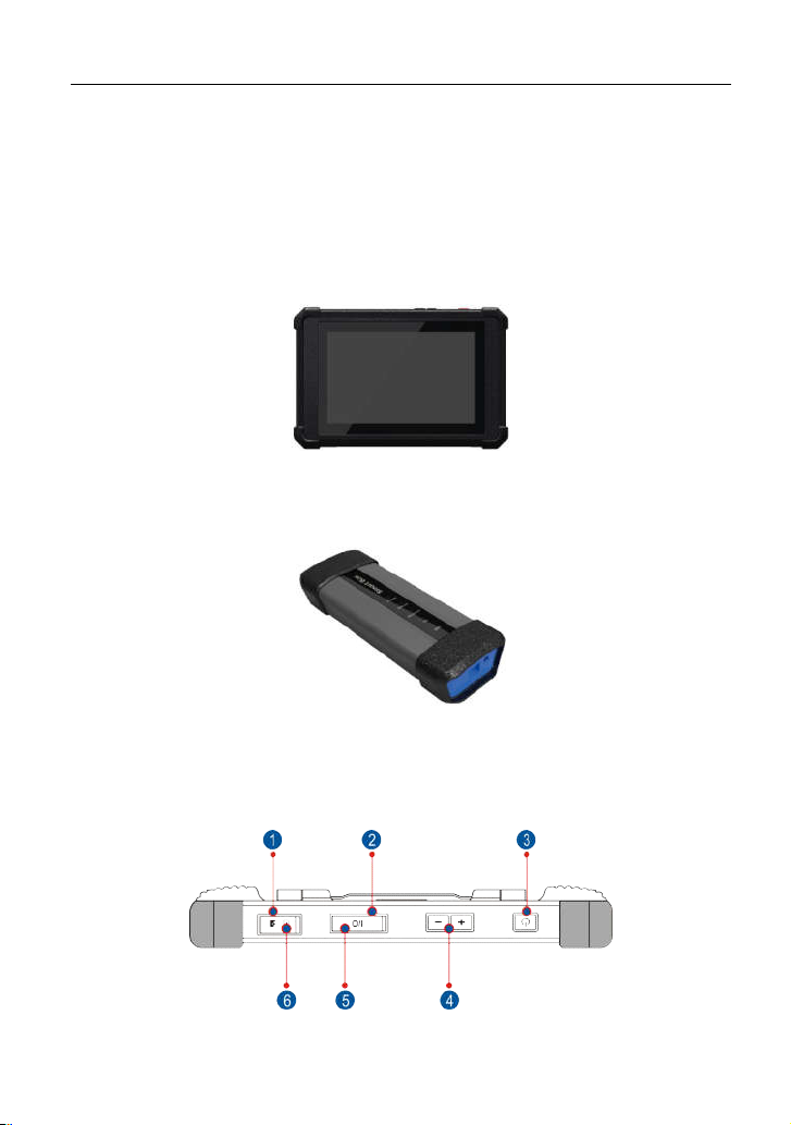
2 Knowledge of S3001
There are two main components to the S3001 system:
S3001 Tablet – the central processor and monitor for the system (See
Chapter “2.1”).
S3001 tablet
VCI Device – the device for accessing vehicle data (See Chapter “2.3”).
Fig. 2-2
2.1 S3001 Tablet
4
Page 13
LAUNCH
S3001 User Manual
Fig. 2-3 S3001 tablet
emory Card Slot
M
1
Ty
2
pe C Charging Port
To store the memory card for storage
expansion.
Reserved for charging the S3001 tablet.
5
Page 14

LAUNCH
S3001 User Manual
ower/Screen Lock
P
3
Button
olume Buttons
V
4
ata Transmission
D
5
Port
S
6
7
8
9
1
1
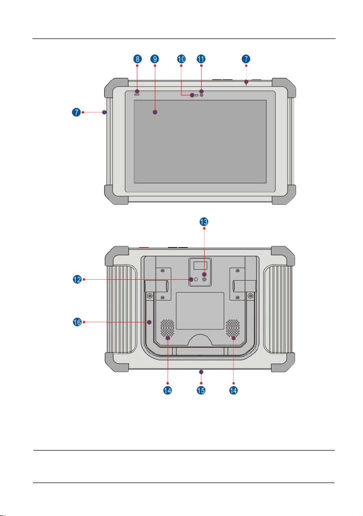
IM Card Slot Only reserved for installing the SIM card.
icrophone
M
Charging indicator
0.1" Capacitive
1
Touch Screen
Ambient Light
0
Sensor
Front Camera
1
To turn the tablet on/off with long press, or
lock the screen with short press.
To adjust the volume.
*Note: Press and hold [POWER] and [VOL -]
key to capture the current screenshot.
Reserved for add-on modules (such as
Batterybox, Scopebox and Sensorbox), and
other devices with similar port.
It illuminates red while S3001tablet is
charging. Once charging is finished, it will
illuminate solid green.
Rear Camera
12
Camera Flash
1
3
Audio Speaker
4
1
Charging Slot
15
16 Adjustable kickstand
F
lip out it to any angle and work comfortable
t your desk, or hang it on automotive part.
a
6
Page 15
LAUNCH
S3001 User Manual
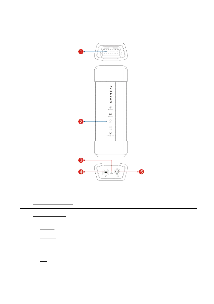
2.2 S30
1 Diagnostic socket: For connecting the diagnostic cable.
01 VCI Device
F
ig. 1-2
LED Indicators: Enables users to easily identify the working status of the
V
CI device. It is defined as follows (From the top to the bottom):
Power: It illuminates solid red when the device is powered on.
ehicle: While communicating with the vehicle, the indicator lights up
V
a
2
nd flashes. Otherwise, it will not illuminate.
BT: Blue indicates the device is working in Bluetooth mode.
It lights up when the device is connected to the diagnostic tool via
I/O:
d
ata cable.
Wireless: It lights up when the device works in wireless
7
Page 16

LAUNCH
communication mode.
3 Reset hole: For resetting the VCI device.
Data I/O port: For connecting it to the handset via USB cable to perform
4
hicle diagnosis.
ve
S3001 User Manual
5 DC
-IN power jack: For connecting the power adaptor.
2.3 Package List
Common accessories for each S3001 are same, but for different destinations,
the accessories of S3001 may vary. For detailed accessory items, please
consult from the local agency or check the packing list supplied with S3001
together.
.
No
1 S3001 tablet
2 S3001 VCI device
3
4 OBD I adaptor
5
6
Item De
OBD II extension
cable
garette lighter
Ci
cable
ttery clamps
Ba
cable
For analyzing the vehicle data and indicating
the test results.
For connecting to vehicle’s OBD II DLC to
access vehicle’s live data.
For connecting the S3001 VCI device for
extension purpose.
For connecting the non-16pin connector to
the S3001 VCI device.
Optional. To supply power to the non-16pin
connector through connection to the
vehicle’s cigarette lighter receptacle.
Optional. To supply power to the non-16pin
connector through connection to the
vehicle’s battery.
scription
Qt.
1
1
1
1
1
1
r charging the tablet.
7 Po
8 Da
wer adaptor
ta cable
Fo
For connecting the S3001 VCI device to the
8
1
1
Page 17

LAUNCH
9 P
assword envelope
S3001 User Manual
tablet to perform vehicle diagnosis.
A
piece of paper bearing Product S/N and
Activation Code, which is needed for
product registration.
1
Non-16pin adaptor
10
ca
ble kit
Optional. For connecting to Non-OBD II
vehicle DLC.
1
9
Page 18

LAUNCH
S3001User Manual
3 Initial Setup
3.1 Charging S3001
*Notes:
•
Only use the included power adaptor to recharge the tablet. Use of any other
adaptor will damage the tool. We assume no responsibility for damage or loss
resulting from using other similar adaptors other than the specified one.
•
Always charge on a non-flammable surface in a well-ventilated area.
To check the battery power level, press and hold the Power button about 3
seconds to turn on the tablet. Power level is indicated as a percentage in the
upper right corner of the screen. If the power level drops below 10% while the
tablet is on, a “Connect Charger” notification will appear on the screen.
1. Connect one end of the power adaptor to DC IN port of the tablet, and the
other end to the AC outle
2
a
. If
ppears on the screen, it indicates it is being charged. If the log
ch
anges into
. Disconnect the power adaptor from the AC outlet.
3
3.2 Po
wer On/Off
, it in
t.
dicates that the battery is fully charged
.
o
1. P
ress and hold the POWER button for about 3 seconds to turn on the tablet.
The system starts initializing and then enters the Home screen.
2. To turn the tablet off, press and hold the POWER button until an option menu
appears. Tap “Power Off”.
3.3 Scre
On-screen keys and status bar are as follows:
en Layout
ig. 3-1
F
10
Page 19

LAUNCH
S3001 User Manual
Tap
1
T
2
screenshots are stored in the Screenshots folder.
3
T
4
or recently used. To open an application, tap it. To remove an
application, swipe it upwards.
5 T
T
6
3.4 A
djusting Screen Brightness
The tablet is equipped with a built-in light intensity sensor. It can adjust the
screen brightness according to the ambient light intensity automatically.
Alternatively, you can also adjust it manually.
1. On the Home screen, tap
. Dra
2
g the slider to adjust it.
Alternatively, user may also slide the “Automatically brightness” switch to ON,
and the system will automatically adjust the screen brightness.
*Tips: Reducing the brightness of the screen is helpful to save the power of the tablet.
to
visit the official website.
ap
sh
ap to display a list of applications that are currently running
ap
ap to return to the previous screen or exit the application.
capture the current screen and all captured
to
ows whether the VCI device is connected properly or not.
to
jump to the Home screen.
Tablet Settings -> Display -> Brightness
.
anging Language
3.5 Ch
T
he handset supports multiple languages. To change the language of the table
lease do the following:
p
. O
1
n the Home screen, tap
2
ap the desired language from the list and the system will change to the
. T
chosen language.
Tablet Settings -> Language
11
.
t,
Page 20

LAUNCH
3.6 Ne
twork Setup
T
he tablet has built-in Wi-Fi that can be used to get online. Once you’re online,
you can register the tablet, browse the Internet, get and update apps and send
email on your network.
*Note: Once WLAN is set as ON, the tablet will consume more power. While WLAN
keeps unused, please turn it off to conserve battery power.
1. On the Home screen, tap
2. Tap or slide the Wi-Fi switch to ON, the tablet starts searching for a
available wireless LANs.
3. Choose the desired Wi-Fi access point / network,
If the network you chose is open, you can connect directly;
If the selected network is encrypted, you have to enter the right security
key (network password).
When this tool is in range, it will connect to the previously linked network
automatically.
Tablet Settings
S3001 User Manual
->
WLAN
.
ll
12
Page 21
LAUNCH
S3001 User Manual
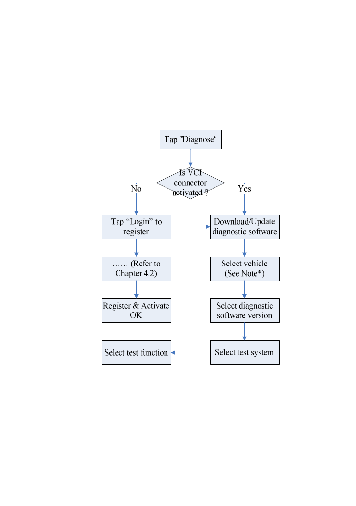
4 Getting Started
4.1 Diagnostic Flowchart
For new users, please follow the operation chart shown in Fig. 4-1 to start
using S3001.
Fig. 4-1
*Note: If “VIN Scan” or “Intelligent Diagnosis” is selected to diagnose a vehicle, this
step shall not apply.
4.2
Register & Download Diagnostic Software
User registration
4.2.1
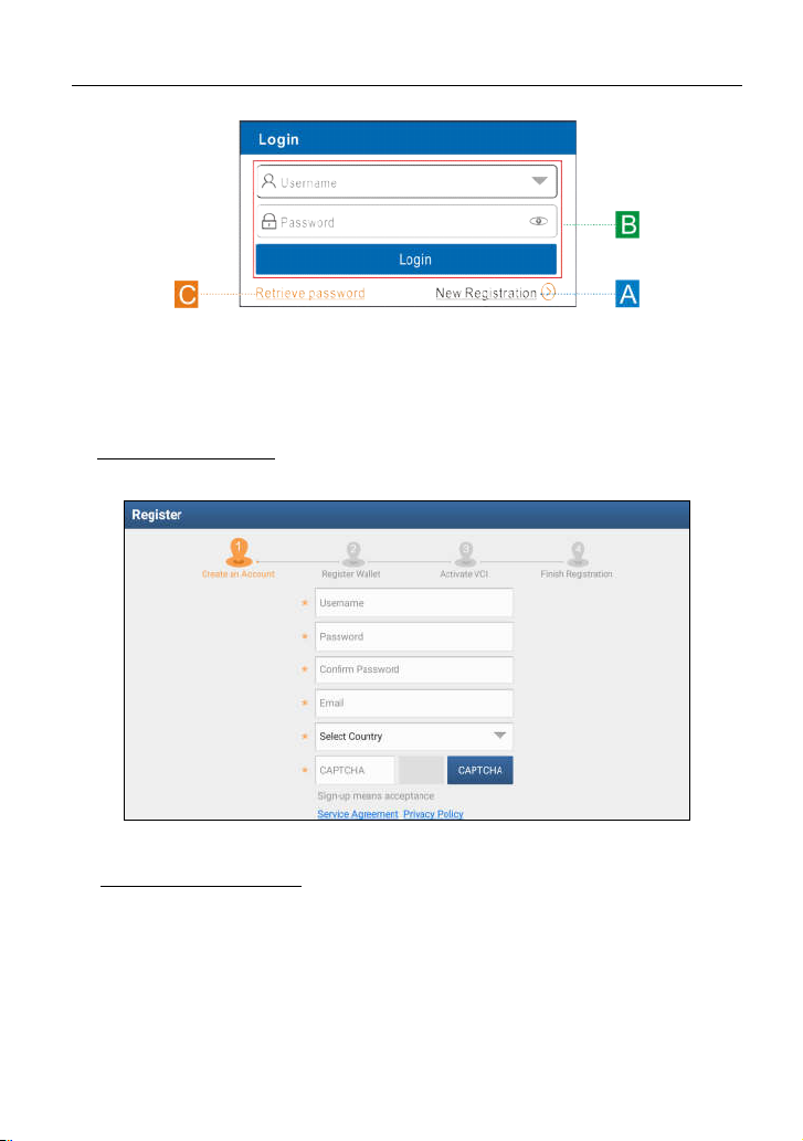
After the tablet is initialized, a screen similar to the following appears.
13
Page 22
LAUNCH
F
ig. 4-2
(If you are a new user, follow A to proceed.)
(If you have registered to be a member, go to B to login the system directly.)
(In case you forgot password, refer to C to reset a new password.)
A. If you are a new user, tap “New Registration” to enter sign-up page. See Fig.
4-3.
S3001 User Manual
F
ig. 4-3
1. Create an App Account: Input the information to create a new account (all
fie
lds must be completed). When finished tap “Register”, a screen similar to
the following will appear:
14
Page 23
LAUNCH
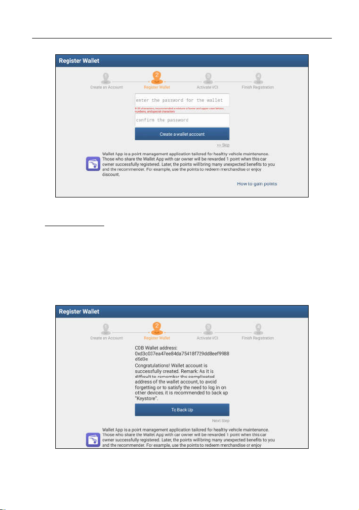
ig. 4-4
F
2. Register Wallet: Input the password for the Wallet (An 8-20 mixture of
lo
wer/upper case letters, numbers and special characters is recommended),
and then tap “Create a Wallet account”.
*Note: You are suggested to note the password down for future use.
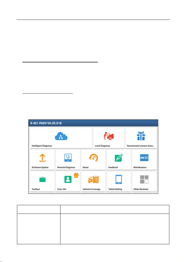
Backup Wallet Address & Keystore: A wallet address is automatically
generated, tap “To Back Up”, and then follow the on-screen instructions to
store it.
S3001 User Manual
ig. 4-5
F
*Note: For detailed backup process, please refer to Chapter 15.6.4.
15
Page 24

LAUNCH
3. Activate VCI: After registering a wallet account, the system navigates to the
fo
llowing screen:
ig. 4-6
F
In Fig. 4-6, input the Product Serial Number and Activation Code, which can be
found in the supplied password envelope.
S3001 User Manual
Product SN
Product SN
Activation code
*No
te: To exit and activate it later, tap “Skip”. In this case, you can activate your VCI by
tapping “Activate VCI” in “Personal Center”. For details, please refer to Chapter 14.4.
Tap “Activate” to finish your registration. A popup displays to ask you to update
the diagnostic software.
To update the diagnostic software, tap “Yes” to enter the vehicle software
download screen. Tap “Update” to start downloading. To pause downloading,
tap “Stop”. To resume, tap “Continue”. When download is complete, the system
will install the software package automatically.
16
Page 25
LAUNCH
S3001 User Manual
*Note: When downloading the diagnostic software or checking for updates, make sure
the tablet has a strong Wi-Fi connection. It may take several minutes to finish it, please
be patient to wait.
To download and install the software later, tap “No”. In this case, enter the Home
screen and tap “Software Upgrade” to download the diagnostic software.
B. If you have registered to be a member, input your name and password, and
the
n tap the “Login” button to enter the main menu screen directly.
*Note: The X-431 PAD V has an auto-save function. Once the username and password
are correctly entered, the system will automatically store it. After initial setup, it is no
longer necessary to input the account information manually to log in.
C. If you forgot the password, tap “Retrieve password” and then follow on-screen
instructions to set a new password.
4.2.2 Home screen
It mainly includes the following items:
telligent
In
D
iagnose
N
ame
Fig. 4-7
D
escription
T
his module allows you to obtain vehicle data from the
cloud server to perform quick test via reading VIN,
hich provides a perfect solution to various defects
w
re
sulting from step-by-step menu selection. In addition,
ser can also check the historical repair records online
u
17
Page 26

LAUNCH
rough this module.
th
Local Diagnose To diagnose a vehicle manually.
T
his option aims to help repair shops or technicians
emote Diagnose
R
R
ecommend
owners bonus
ken
to
unch instant messaging and remote diagnosis,
la
m
aking the repair job getting fixed faster.
W
allet App is a point (token) management application
ta
ilored for healthy vehicle maintenance. Those who
are the Wallet App with car owner will be rewarded 1
sh
oint (token) when this car owner successfully
p
gistered. Later, the points will bring many unexpected
re
enefits to you and the recommender. For detailed
b
o
perations, please refer to Chapter 15.6.
S3001 User Manual
oftware Update
S
R
eset
eedback
F
M
aintenance
U
ser Info
Tab
let Setting
Vehicle Coverage
Toolbox
o update vehicle diagnostic software and APK.
T
o perform all kinds of common repair & maintenance
T
ite
ms, including electronic throttle position reset, ABS
bleeding, DPF regeneration, oil lamp reset etc.
te: This module only applies to Passenger Vehicle
*No
/Gaso
line & Diesel Version.
o feed back the recent 20 diagnostic logs to us for
T
iss
ue analysis.
Ab
undant maintenance data are available, which helps
re
pair professionals diagnose and repair vehicles
fficiently, accurately and profitably.
e
To manage VCI, diagnostic reports & records, change
pa
ssword, configure printer, sample data and logout /
lo
gin etc.
C
onfigures the system setting of the tablet.
T
o check the vehicle models supported on the X-431
PAD V.
Includes Camera, Browser, Oscilloscope, Ignition,
nsor, Multimeter, Battery etc.
Se
18
Page 27
LAUNCH
ther Modules
O
ehicle menu layout
4.2.3 V
cludes TeamViewer, Email, Browser, and product
In
anual etc.
m
S3001 User Manual
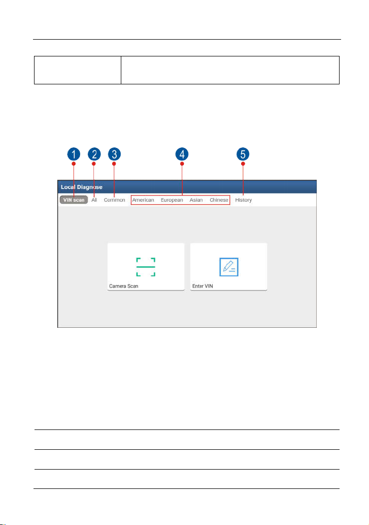
After downloading the diagnostic software, you can go to “Local Diagnosis” to
check if all software are completely downloaded and installed.
Tap “Local Diagnosis”, a screen similar to the following figure appears:
ig. 4-8
F
VINScan
button: Tap it to scan the Vehicle Identification Number (VIN)
code of your vehicle. OBD VIN and INPUT VIN are included. This
function does not apply to the commercial vehicles.
1
*Note: Before using this function, the corresponding diagnostic software and
Auto search file need to be downloaded on your tool first while downloading
the diagnostic software.
2 All
3 C
Tab: Displays all the vehicle makes in the vehicle menu.
ommon
Tab: Displays all frequently-used vehicle makes.
4 Regional buttons: Tap different buttons to switch to corresponding
19
Page 28
LAUNCH
vehicles. If you have purchased an S3001of Gasoline & Diesel
Version, a Heavy-duty tab will appear next to the regional button.
History Button: Generally once a vehicle diagnosis is performed,
S3001 will record the every details of diagnostic process. This
5
function provides a quick access to the previously tested vehicles.
Testing can be resumed from the previous operation without starting
from scratch.
iagnostics toolbar
4.2.4 D
The diagnostics toolbar contains a number of buttons that enable various
procedures. It is displayed at the top of the vehicle diagnostic screen throughout
the whole diagnostic session. Refer to the table below for a brief description of
the functions of the diagnostics toolbar buttons:
S3001 User Manual
H
P
rint
ome
N
ame
ig. 4-9
F
on
Ic
eturn to the Home screen.
R
T
ap to print the current screen. To perform
printing, you need to purchase an extra Wi-Fi
p
rinter manufactured by LAUNCH separately
a
nd then properly configure the wireless printer
llowing the steps described in Chapter 15.3.
fo
20
unction
F
Page 29

LAUNCH
S3001 User Manual
table Model
Tes
P
ersonal Center
xit
E
Inquires the vehicle models that the
S3001 supports.
Q
uick access to personal center.
it the diagnostic application.
Ex
4.3 Diagnosis Methods
S3001 tablet supports 2 communication methods with the S3001 VCI device:
Wi-Fi and data cable. You may choose any one of the methods to diagnose a
vehicle.
*Notes:
To obtain stable communication, you are strongly recommended to perform the
vehicle diagnosis via USB cable. In this case, the USB cable is required to connect
the S3001 VCI device and the tablet.
When all communication methods are applied at the same time, the S3001
system will use the USB communication as the default priority.
4.4 Connections
4.4.1 Preparation
Normal testing conditions
urn on the vehicle power supply.
T
Throttle should be in a closed position.
4.4.2 DLC location
The DLC (Data Link Connector) is typically a standard 16 pin connector where
diagnostic code readers interface with the vehicle’s on-board computer. The
DLC is usually located 12 inches from the center of the instrument panel (dash),
under or around the driver’s side for most vehicles. If Data Link Connector is not
located under dashboard, a label should be there telling location. For some
Asian and European vehicles, the DLC is located behind the ashtray and the
ashtray must be removed to access the connector. If the DLC cannot be found,
refer to the vehicle’s service manual for the location.
21
Page 30
LAUNCH
F
ig. 4-11
S3001User Manual
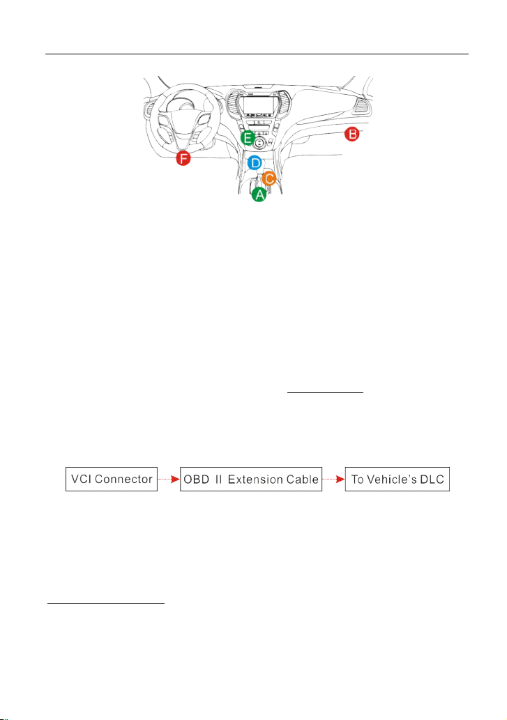
4.4.3 Vehicle connection (For Passenger Vehicle Version)
The method used to connect the diagnostic connector to a vehicle’s DLC
depends on the vehicle’s configuration as follows:
A vehicle equipped with an OBD II management system supplies both
communication and 12V power through a standardized DLC.
A vehicle not equipped with an OBD II management system supplies
communication through a DLC connection, and in some cases supplies 12V
power through the cigarette lighter receptacle or a connection to the vehicle
battery.
Follow the steps mentioned below to connect OBD II vehicle:
1
. Locate vehicle’s DLC socket.
2. Plug the S3001 VCI device into the vehicle’s DLC socket (It is suggested
u
se the OBD II extension cable to connect the S3001 VCI device and DL
cket).
so
to
C
Fig. 4-12
3. Choose one of the two ways to obtain power from:
A. Power adaptor: Connect one end of the included power adaptor to DC IN
port of S3001 tablet, and the other end to AC outlet. B.
Internal battery pack
For non-OBDII vehicle, proceed as follows:
1. Locate vehicle’s DLC socket.
2. Select the corresponding non-16pin connector.
3. Plug the non-16pin end of the connector into the DLC socket, and the other
end to the OBD I adaptor, and then tighten the captive screws.
22
Page 31

LAUNCH
S3001 User Manual
4. Connect the other end of the adaptor to the included S3001 VCI device.
5. To supply power to OBD I adaptor from:
A. Cigarette Lighter Cable: Connect one end of the cigarette lighter cable to
v
ehicle’s cigarette lighter receptacle, and the other end to the power jack o
BD I adaptor.
O
ig. 4-13
F
B. Battery Clamps Cable: Connect one end of the battery clamps cable to
ehicle’s battery, and the other end to the power jack of OBD I adaptor.
v
f
ig. 4-14
F
4.3.3 Vehicle connection (For Commercial Vehicle/ Gasoline & Diesel
Version)
The method used to connect the S3001 VCI device to a vehicle’s DLC depends
on the vehicle’s configuration as follows:
A. OBD II Vehicle Connection: Plug one end of the diagnostic cable into the
vehicle’s DLC, and the other end into the diagnostic socket of the S3001 VCI
device, and then tighten the captive screws.
F
ig. 4-12
B. Non-OBD II Vehicle Connection: For vehicles with non-OBD II diagnostic
socket, a non-16pin connector (adaptor cable) is required.
23
Page 32

LAUNCH
Fig. 4-13
*Notes:
a). For commercial vehicles, refer to the above connection method to proceed.
b
). For passenger vehicles, replace the “Non-16pin connector” with “OBD I adaptor” +
“non-16pin connector (for passenger vehicles)”. Other connections shall also apply.
S3001 User Manual
4.5 Communication Setup
There are two kinds of ways available for the tablet to communicate with the
S3001 VCI device: Wi-Fi and USB cable.
The USB cable connection is a simple & quick way to establish communication
between the tablet and the VCI module. After properly connecting the USB cable
from the tablet to the VCI, the VCI navigation button at the bottom of the screen
becomes highlighted indicating the USB connection is successful.
*Note: The USB connection provides the most stable and fastest communication.
When all communication methods are applied at the same time, the S3001
system will use the USB communication as the default priority.
24
Page 33

LAUNCH
S3001 User Manual
5 Diagnosis
Intelligent Diagnosis
5.1
hrough simple Wi-Fi communication between the tablet and VCI device, you
T
can easily get the VIN (Vehicle Identification Number) information of the
currently identified vehicle. Once the VIN is successfully identified, the system
will retrieve it from the remote server and then guide you to vehicle information
page without performing the step-by-step manual menu selection.
The vehicle information page lists all historical diagnostic records of the vehicle,
which lets the technician have a total command of the vehicle faults. In addition,
a quick dial to local diagnosis and diagnostic function are also available on this
page for reducing the roundabout time and increasing productivity.
*Notes:
•
Before using this function, please make sure the VCI device is properly connected
to the vehicle’s DLC. For detailed connection, see Chapter 4.3.3.
•
A stable network connection is required for this function.
Follow the steps below to proceed.
1. Tap “Diagnose” on the Diagnostics function module and tap “AutoDetect” to
enter Fig. 5-1.
F
ig. 5-1
*Note: If the S3001 VCI device is not paired up with the tablet before doing this step, a
25
Page 34

LAUNCH
prompt message box will appear:
. 5-2
Fig
Check all the possible reasons of Bluetooth connection failure carefully, and then tap
“Confirm”.
S3001 User Manual
Fig. 5-3
If the S3001 VCI device was once used with other devices, you need to cancel the
pairing of the connector first via either one of the following ways:
•
Tap “Tablet Settings” -> “Bluetooth” -> Choose the desired S3001 VCI device from
the Paired list. Tap “
•
Tap “Settings” -> “VCI Management” -> Tap “Deactivate matching”.
Tap “Scan” to start searching for the S3001 VCI device and pairing up with it
d then tap “FORGET” to unpair it.
“, an
26
.
Page 35

LAUNCH
. 5-4
Fig
2. After pairing is complete, the handset starts reading the vehicle VIN.
A. If the VIN can be found from the remote server database, a screen similar to
F
ig. 5-5 displays:
S3001 User Manual
F
ig. 5-5
• Tap “Diagnostic” to start a new diagnostic session.
• Tap “Maintenance record” to view its historical repair record. If there are
records available, it will be listed on the screen in sequence of date. If no
records exist, the screen will show “No Record”.
27
Page 36

LAUNCH
Fig. 5-6
• Tap “View record” to view the details of the current diagnostic report.
• To perform other functions, tap “Quick access” to directly go to the fun
se
lection screen. Choose the desired one to start a new diagnostic
session.
B. If the handset failed to access the VIN information, the screen will display as
elow:
b
S3001 User Manual
ction
F
ig. 5-7
In this mode, you need to input the VIN manually or tap
28
to
scan it.
Page 37

LAUNCH
S3001 User Manual
1) Tap “
launch the VIN recognition module.
“ to
F
ig. 5-8
Place the VIN inside the viewfinder rectangle to scan it. The most
recognizable location for this number is in the top left corner on the
vehicle’s dashboard. Other locations include the driver’s door or post, and
the firewall under the hood.
• If you have scanned the VIN of the vehicle, tap
to
choose it from
the record list.
• In case the handset failed to detect it, tap
enter it manually.
to
• To turn the flash on, tap .
After scanning, the screen automatically displays the result.
F
ig. 5-9
• If the VIN scanned is incorrect, tap the result field to modify it and then
tap “OK”. If the VIN exists on the remote server, the system will enter
the vehicle information screen. See Fig. 5-5.
• To scan it again, tap “REPEAT”.
2) Input the VIN, and tap “OK”, the system will automatically identify the
vehicle model and directly navigate to the vehicle information page.
In general, vehicle identification numbers are standardized - all contain
ch
aracters. VIN characters may be capital letters A through Z and numbe
through 0; however, the letters I, O and Q are never used in order to avoi
1
m
istakes of misreading. No signs or spaces are allowed in the VIN.
17
29
rs
d
Page 38

LAUNCH
Tap “SKIP” to go to Diagnostics main menu screen.
5.2
Local Diagnosis
ap “Local Diagnosis” to enter the vehicle selection page.
T
Fig. 5-10
2 approaches are provided for you to access the vehicle diagnostic software.
Choose any one of the following ways:
. V
1
INSCAN enables you to access it more quickly
this case, automatic scan (OBD VIN) and manual input (INPUT VIN) are
In
available.
In Fig. 5-10, tap “VINScan”, the screen displays as follows:
S3001 User Manual
.
ig. 5-11
F
A. Camera Scan: In this mode, the S3001 VCI device should be plugged into
e vehicle’s DLC first, and then a Bluetooth communication should be
th
established between X-431 PAD V and the vehicle.
30
Page 39

LAUNCH
S3001 User Manual
Tap “Camera Scan”, a screen similar to the following appears:
ig. 5-12
F
Place the VIN inside the viewfinder rectangle to scan it. The most recognizable
location for this number is in the top left corner on the vehicle’s dashboard. Other
locations include the driver’s door or post, and the firewall under the hood.
• If you have scanned the VIN of the vehicle, tap to choose it from the
record list.
• In case the handset failed to recognize it, tap
• To turn the flash on, tap
O
nce the test vehicle is successfully identified, X-431 PAD V will jump to the
.
to
enter it manually.
function selection page directly.
Fig. 5-13
Tap the desired option to perform the corresponding function.
*Note: Before using this function, the corresponding diagnostic software and Auto
search file need to be downloaded on your tool first while downloading the diagnostic
31
Page 40

LAUNCH
software.
B. INPUT VIN: In this mode, you need to input the VIN manually. In general,
ehicle identification numbers are standardized - all contain 17 characters.
v
VIN characters may be capital letters A through Z and numbers 1 through 0;
however, the letters I, O and Q are never used in order to avoid mistakes of
misreading. No signs or spaces are allowed in the VIN.
Tap “INPUT VIN” and a screen similar to Fig. 5-14 will appear:
F
ig. 5-14
put the VIN, and tap “Confirm”, the system will automatically identify the
In
vehicle model and directly navigate to the function selection page.
. T
2
ap a corresponding diagnostic software logo, and then follow the
on-screen instruction to access the diagnostic software.
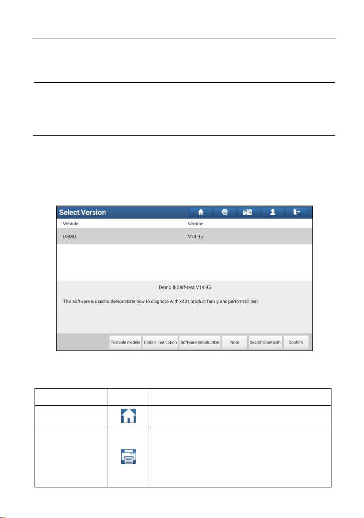
Take Demo as an example to demonstrate how to diagnose a vehicle.
1). Select diagnostic software version: Tap the “DEMO” to go to Step 2.
re than one version is available on this handset, it will be listed on the screen.)
mo
S3001 User Manual
(*Note: If
Fig. 5-15
32
Page 41

LAUNCH
S3001 User Manual
On-screen Buttons:
Testable models:
ftware covers.
so
Update instruction:
Software introduction:
Tap to read some precautions on using the current diagnostic software.
Note:
Confirm:
2
Tap it to go to next step.
). Select test item: Select the desired test item to proceed.
Tap to view the vehicle models that the current diagnostic
Tap to view the optimized items and enhancements.
Tap to check the software function list.
ig. 5-17
F
5.2.1 Health Report (Quick Test)
This function varies from vehicle to vehicle. It enables you to quickly access all
the electronic control units of the vehicle and generate a detailed report about
vehicle health.
Tap “Health Report”, the system start scanning the ECUs and the screen
displays as follows:
33
Page 42

LAUNCH
ig. 5-18
F
(To stop the system scanning, tap “Pause”.)
Once the scanning is complete, a screen similar to the following appears:
S3001 User Manual
ig. 5-19
F
In Fig. 5-19, the tested system with fault code appears in red and the system
with OK displays in black (normally).
On-screen Buttons:
C
lear DTC:
Tap to clear the existing diagnostic trouble codes.
34
Page 43

LAUNCH
S3001 User Manual
Fault Report:
On-screen Buttons:
earch:
S
se
arch for more detailed information about the selected DTC online.
Report:
Tap to view the health report in details.
ig. 5-20
F
Highlight a certain DTC item, and then tap it to launch the browser to
To save the current data in text format.
F
ig. 5-21
Input the required information, and then tap “Confirm” to save it.
Alternatively you can also set the workshop information in “Personal Center” ->
“Settings” -> “Print Information”. Once you configured the information, it will be
35
Page 44

LAUNCH
S3001 User Manual
automatically generated every time you saved the diagnostic report. All vehicle
and workshop information will be appended to the diagnostic report.
To skip the workshop information, tap “Skip” to go to the next step.
All reports are saved under the tab “Diagnostic Report” in “My Report” from
“Personal Center” menu. For details on report operations, please refer to
Chapter 14.1 “My Report”.
.2.2 System Scan
5
This option allows you to quickly scan which systems are installed on the
vehicle.
In Fig. 5-17, tap “System Scan”, the system start scanning the systems. Once
the scanning is complete, the screen will display the result. See Fig. 5-22.
F
ig. 5-22
Tap the desired system to advance to the test function selection page. For
detailed operations on test function, please refer to Chapter 5.2.3.
5.2.3 System Selection
This option allows you manually select the test system and function step by step.
In Fig. 5-17, tap “System Selection”, the screen displays as follows:
36
Page 45

LAUNCH
ig. 5-23
F
Swipe the screen from the bottom to view the vehicle system on the next page.
Tap the desired system (take “ECM” for example) to jump to the test function
page.
ig. 5-24
F
*Note: Different vehicle has different diagnostic menus.
S3001 User Manual
A. Version Information
This function is used to read the version information of system mode, vehicle
VIN, software and ECU.
In Fig. 5-24, tap “Version Information”, the screen displays as Fig. 5-25.
ig. 5-25
F
37
Page 46

LAUNCH
S3001 User Manual
Tap “OK” to confirm and exit.
B. Read Fault Code
This function displays the detailed information of DTC records retrieved from the
vehicle’s control system.
In Fig. 5-24, tap “Read DTC”, the screen will display the diagnostic result.
ig. 5-26
F
On-screen Buttons:
Fr
eeze Frame: When an emission-related fault occurs, certain vehicle conditions are
recorded by the on-board computer
his information is referred to as freeze frame
. T
data. Freeze frame data includes a snapshot of critical parameter values at the
time the DTC is set.
Tap to view the help information.
Help:
R
elated Search:
nline.
o
To save the current data in text format.
Report:
iagnostic Report” in “My Report” from “Personal Center” menu. For details on
“D
report operations, please refer to Chapter 15.1 “My Report”.
. Clear Fault Memory
C
Tap it to search for more information about the current DTC
All
reports are saved under the tab
After reading the retrieved codes from the vehicle and certain repairs have been
carried out, you can use this function to erase the codes from the vehicle. Before
performing this function, please be sure the vehicle’s ignition key is in the ON
38
Page 47

LAUNCH
S3001 User Manual
position with the engine off.
In Fig. 5-24, tap “Clear Fault Memory”, a confirmation dialog box pops up on the
screen.
ig. 5-27
F
Tap “Yes”, the system will automatically delete the currently existing trouble
code.
*Note: The trouble code will not disappear until the trouble was completely cleared.
D. Read Data Stream
Th
is option retrieves and displays live data and parameters from the vehicle’s ECU.
In Fig. 5-24, tap “Read Data Stream”, the system will display data stream items.
F
ig. 5-28
On-screen Buttons:
Select All:
eam item, just check the box before the item name.
str
Unselect:
Tap it to select all items of the current page. To select certain data
Tap it to deselect all data stream items.
39
Page 48

LAUNCH
S3001 User Manual
Confirm:
A
Tap it to confirm and jump to the next step.
fter selecting the desired items, tap “Confirm” to enter the data stream reading
page.
ig. 5-29
F
Notes:
1. If the value of the data stream item is out of the range of the standard (reference)
value, the whole line will display in red. If it complies with the reference value, it
displays in blue (normal mode).
2. The indicator 1/X shown on the bottom of the screen stands for the current
page/total page number. Swipe the screen from the right/left to advance/return to
the next/previous page.
There are 3 types of display modes available for data viewing, allowing you to
view various types of parameters in the most suitable way.
Value – this is the default mode which displays the parameters in texts a
ows in list format.
sh
nd
Graph – displays the parameters in waveform graphs.
ombine – this option is mostly used in graph merge status for data
C
co
mparison. In this case, different items are marked in different colors.
On-screen Buttons:
Combine:
this case, different items are marked in different colors. Tap it to select the
In
This option is mostly used in graph merge status for data comparison.
desired items, and then tap “Confirm” to view the merged items in graph. See
40
Page 49

LAUNCH
Fig. 5-30 & Fig. 5-31.
ig. 5-30
F
S3001 User Manual
ig. 5-31
F
reports are saved under the tab
To save the current data in text format.
Report:
iagnostic Report” in “My Report” from “Personal Center” menu. For details on
“D
report operations, please refer to Chapter 15.1 “My Report”.
Record:
T
Tap to start recording diagnostic data for future playback and analysis.
he saved file follows the naming rule: It begins with vehicle type, and then the
All
record starting time and ends with .x431 (To differentiate between files, please
configure the accurate system time). The file is stored in “My Report” under
41
Page 50

LAUNCH
“Personal Center” menu.
Tap to view the help information.
Help:
S3001 User Manual
Gra
E. Actuation Test
This option is used to access vehicle-specific subsystem and component tests.
Available test vary by vehicle manufacturer, year, and model.
During the actuation test, the S3001 handset outputs commands to the ECU in
order to drive the actuators, and then determines the integrity of the system or
parts by reading the ECU data, or by monitoring the operation of the actuators,
such as switching a injector between two operating states.
In Fig. 5-24, tap “Actuation Test”, the system will display as follows:
Tap it to view the waveform.
ph:
Fig. 5-32
42
Page 51

LAUNCH
F
ig. 5-33
Simply follow the on-screen instructions and make appropriate selections to
complete the test. Each time when an operation is successfully executed,
“Completed” displays.
S3001 User Manual
5.3 Remote Diagnosis
This option aims to help repair shops or technicians launch instant messaging
and remote diagnosis, making the repair job getting fixed faster.
Tap “Remote Diagnosis” on the Home screen, the screen appears blank by
default.
5.3.1 Interface layout
ig. 5-34
F
43
Page 52

LAUNCH
S3001 User Manual
Directly input the username of the S3001 to start
1 Search bar
searching, and then tap the desired one to add it into
your friend list.
2 Home button Tap it to navigate to the Home screen.
ce an incoming message reaches, a red dot will appear
3 Me
ssage tab
ntact tab Tap to enter the friend list.
4 Co
On
on the upper right corner of the tab.
Tap to slide the switch to ON, the S3001 keeps online
WEB Remote
5
switch
and becomes visible on the web client. In this case,
inform the technician of your product S/N, and he/she will
control your S3001 remotely.
5.3
.2 Add friends
Tap “Contact” to enter the contact page. By default it appears blank.
In the search bar, input the partner’s username and tap “Search” button next to
the search bar to starts searching from Launch’s golo business database.
The partner must be the users who have registered their Launch’s diagnostic
tools. They may be the following:
Workshop
Technician
golo users
Once the result matches the keyword, a screen similar to the following will
appear:
44
Page 53

LAUNCH
Fig. 5-35
Tap “Add”, a dialog box pops up:
ig. 5-36
F
Tap “CONFIRM” to send your request.
Once the partner receives the request, a beep will sound. Tap the “Message”
tab:
• Once the partner agreed your request, he/she will automatically be listed in
the Contact tab.
• If a technician sent you a friend request, you can tap “Agree” to confirm and
his/her name will appear in the friend list (Contact). Or tap “Ignore” to ignore
this request.
5.3.3 Start instant messaging
*Note: The I/M (Instant Messaging) function is open to all users who had Launch’s
diagnostic tool equipped with this module.
After adding your friends, tap the desired one’s photo to enter a screen similar to
the following:
S3001 User Manual
45
Page 54

LAUNCH
F
ig. 5-37
S3001 User Manual
Tap the input field and use the on-screen keyboard to enter the text message,
and then tap “Send” to send it.
Tap
Tap
Tap
send the voice message.
to
send the emoj.
to
call out more function options.
to
Fig. 5-38
File: Choose diagnostic reports or local files to send.
P
icture: Choose screenshots or pictures to send.
emote Diagnostic: To start a remote diagnostic session. For details, refer to
R
hapter 5.3.4.
C
Camera: Open camera to take pictures.
46
Page 55

LAUNCH
S3001 User Manual
5.3.4 Launch remote diagnosis (Device-To-Device)
The S3001 handset is allowed to launch remote diagnosis with other
diagnostic tools (including but not limited to the S3001) of Launch family, which
are equipped with this module.
* Note: Before performing this operation, please make sure the following no matter
which side sends the remote request:
Turn on the vehicle power supply.
Throttle should be in a closed position.
The S3001 should be properly connected to the vehicle’s DLC and a
successful communication is required.
In Fig. 5-38, tap “Remote Diagnostic”, a pull-down menu including the following
options appears:
F
ig. 5-39
These options are defined as follows:
Actions Results
T
S
end remote
diagnostic reservation
ap it and input the reservation title or scheduled date
of the remote diagnosis, and then tap “Confirm” to
send.
Request to control the partner’s device remotely to
help him diagnose the vehicle.
*Notes:
equest control
R
remote device
Remote diagnosis has the same diagnostic steps as
manual diagnosis.
In process of remote diagnosis, tap the
send a voice message.
Once vehicle diagnosis is complete, a report will be
47
utton to
b
Page 56

LAUNCH
cre
ated. Input your comments on this report, and then
tap
“Send Report” to send it to the partner.
Tap “Request control remote device”
St
art connecting after request confirmed
If you need support, just use this option to invite a
technician to perform a remote control on your tool.
*Notes:
Remote diagnosis has the same diagnostic steps as
manual diagnosis.
In
vite remote
diagnostic assistant
In process of remote diagnosis, tap the button to
send voice message.
Once you received the report from the partner, tap
“View Report” to view details. All diagnostic reports
are saved under the “Remote Diagnostic Reports” tab
of “My Reports” in “Personal Center”.
S3001 User Manual
W
ait for partner’s confirmation
St
art Diagnosis
nerate diagnostic report
Ge
48
Page 57

LAUNCH
S3001 User Manual
Cancel To cancel this operation.
49
Page 58

LAUNCH
5.3.5 Launch remote diagnosis (Device-To-PC)
Except that the remote diagnosis can be done between different Launch’s
diagnostic tools that come loaded with the module, user also can ask for remote
control from PC client technician.
S3001 User Manual
ig. 5-40
F
Tap the “Web Remote” tab, the screen displays as follows:
50
Page 59

LAUNCH
F
ig. 5-41
1. Slide the switch “Allow device to be connected to the WEB client remote
diagnostic device” to ON so that the partner can find and access to this
device while using the PC.
2. Notify the partner of the PC client website http://remote.x431.com/cn/. When
the partner opens the link, the PC displays as below:
*Note: Before processing remote diagnosis, please make sure the tablet is properly
connected to the vehicle.
S3001 User Manual
Fig. 5-42
51
Page 60

LAUNCH
3. Tell the partner to input his own official technician account and password, and
th
en tap “Login” to navigate to the following figure
S3001 User Manual
.
Fig. 5-43
4. Tell the partner to check the box “Serial number” and enter the Serial Number
provided by you, and then tap “Start remote diagnosis”.
5. A popup displays to ask for your confirmation to allow remote control on your
device.
6. Tap “Allow” to accept, or tap “Deny” to reject.
In process of remote diagnosis, please note the following things:
1) You are not suggested to execute any actions.
2) The partner is not allowed to save any diagnostic reports or records on
your handset.
The operations in remote diagnosis are same as those in local diagnosis. Once
the session is complete, a remote diagnostic report will be automatically
generated.
5.4 How to View Diagnostic History?
Generally once a vehicle diagnosis is performed, S3001 will record the
52
Page 61

LAUNCH
every details of diagnostic process. The History function provides direct access
to the previously tested vehicles and users can resume from the last operation,
without the necessity of starting from scratch.
Tap “Diagnostic History” on the Home screen, all diagnostic records will be listed
on the screen in date sequence.
ig. 5-44
F
• Tap certain vehicle model to view the details of the last diagnostic report.
• To delete certain diagnostic history, select it and then tap “Delete”. To
d
elete all historical records, tap “Select All” and then tap “Delete”.
• Tap “Quick access” to directly navigate to the function selection page of
last diagnostic operation. Choose the desired option to proceed.
S3001 User Manual
5.5 Ho
w to Feedback Diagnostic Logs?
his item allows you to feedback your diagnostic problems to us for analysis and
T
troubleshooting.
Tap “Feedback”, a pop-up message will appear:
53
Page 62

LAUNCH
Fig. 5-45
Tap “CONFIRM” to choose the vehicle diagnostic record page.
S3001 User Manual
F
ig. 5-46
A). Tap the desired vehicle to enter the diagnostic log selection page.
54
Page 63

LAUNCH
ig. 5-47
F
Select the check box and tap “Submit”. A screen similar to the following will
appear:
S3001 User Manual
F
ig. 5-48
Choose the failure type and fill in the detailed failure description in the blank text
box and telephone or email address. After inputting, tap “Submit Result” to send
it to us.
B). Tap “History”, the diagnostic logs marked with different color indicate the
process status of the diagnostic feedback. Green/Red/Blue means the
diagnostic feedback is fixed/pending/in process respectively.
55
Page 64

LAUNCH
S3001 User Manual
6 Special (Reset) Function (Only for Passenger
Vehicle/Gasoline & Diesel Version)
In addition to amazing & powerful diagnostic function, S3001 also features
various service functions. The most commonly performed service functions
contain:
Oil Reset Service
Electronic Parking Brake Reset
Steering Angle Calibration
ABS Bleeding
TPMS (Tire Pressure Monitor System) Reset
Gear Learning
IMMO Service
Injector Coding
Battery Maintenance System
Diesel Particulate Filter (DPF) Regeneration
Electronic Throttle Position Reset
There are two methods to reset service lamp: Manual reset or Auto reset. Auto
reset follows the principle of sending command from the tool to vehicle’s ECU to
do resetting. While using manual reset, users just follow the on-screen
instructions to select appropriate execution options, enter correct data or values,
and perform necessary actions, the system will guide you through the complete
performance for various service operations.
56
Page 65

LAUNCH
Sel
ect “Reset”
Sel
ect the desired reset
item (e.g. oil lamp reset
etc.)
on the screen to operate
Sel
(The available mode varies
S3001 User Manual
Foll
ow the instructions
ect the service mode
from vehicle to vehicle)
Select the car brand
Figure 6-1
6.1
Oil Reset Service
T
his function allows you to perform reset for the engine oil life system, which
calculates an optimal oil life change interval depending on the vehicle driving
conditions and climate.
This function can be performed in the following cases:
1. If the service lamp is on, you must provide service for the car. After service,
you need to reset the driving mileage or driving time so that the service lamp
turns off and the system enables the new service cycle.
2. After changing engine oil or electric appliances that monitor oil life, you need
to reset the service lamp.
6.2 Electronic Parking Brake Reset
. If the brake pad wears the brake pad sense line, the brake pad sense line
1
sends a signal sense line to the on-board computer to replace the brake pad.
After replacing the brake pad, you must reset the brake pad. Otherwise, the
car alarms.
2. Reset must be performed in the following cases:
) Th
a
e brake pad and brake pad wear sensor are replaced.
b) The brake pad indicator lamp is on.
c)
The brake pad sensor circuit is short, which is recovered.
) Th
d
e servo motor is replaced.
57
Page 66

LAUNCH
6.3 St
eering Angle Calibration
T
o reset the steering angle, first find the relative zero point position for the car to
drive in straight line. Taking this position as reference, the ECU can calculate the
accurate angle for left and right steering.
After replacing the steering angle position sensor, replacing steering mechanical
parts (such as steering gearbox, steering column, end tie rod, steering knuckle),
performing four-wheel alignment, or recovering car body, you must reset the
steering angle.
ABS Bleeding
6.4
This function allows you to perform various bi-directional tests to check the
operating conditions of Anti-lock Braking System (ABS).
1. When the ABS contains air, the ABS bleeding function must be performed to
bleed the brake system to restore ABS brake sensitivity.
2. If the ABS computer, ABS pump, brake master cylinder, brake cylinder, brake
line, or brake fluid is replaced, the ABS bleeding function must be performed
to bleed the ABS.
S3001 User Manual
6.5 Tire Pressure Monitor System Reset
his function allows you to quickly look up the tire sensor IDs from the vehicle’s
T
ECU, as well as to perform TPMS replacement and sensor test.
1. After the tire pressure MIL turns on and maintenance is performed, the tire
pressure resetting function must be performed to reset tire pressure and turn
off the tire pressure MIL.
2. Tire pressure resetting must be performed after maintenance is performed
th
e following cases: tire pressure is too low, tire leaks, tire pressure
monitoring device is replaced or installed, tire is replaced, tire pressure sensor
is damaged, and tire is replaced for the car with tire pressure monitoring
function.
in
ear Learning
6.6 G
he crankshaft position sensor learns crankshaft tooth machining tolerance and
T
saves to the computer to more accurately diagnose engine misfires. If tooth
learning is not performed for a car equipped with Delphi engine, the MIL turns on
after the engine is started. The diagnostic device detects the DTC P1336 'tooth
not learned'. In this case, you must use the diagnostic device to perform tooth
58
Page 67

LAUNCH
learning for the car. After tooth learning is successful, the MIL turns off.
After the engine ECU, crankshaft position sensor, or crankshaft flywheel is
replaced, or the DTC 'tooth not learned' is present, tooth learning must be
performed.
S3001 User Manual
6.7 IMMO
A
n immobilizer is an anti-theft mechanism that prevents a vehicle’s engine from
starting unless the correct ignition key or other device is present. Most new
vehicles have an immobilizer as standard equipment. An important advantage of
this system is that it doesn’t require the car owner to activate it since it operates
automatically. An immobilizer is considered as providing much more effective
anti-theft protection than an audible alarm alone.
As an anti-theft device, an immobilizer disables one of the systems needed to
start a car’s engine, usually the ignition or the fuel supply. This is accomplished
by radio frequency identification between a transponder in the ignition key and a
device called a radio frequency reader in the steering column. When the key is
placed in the ignition, the transponder sends a signal with a unique identification
code to the reader, which relays it to a receiver in the vehicle’s computer control
module. If the code is correct, the computer allows the fuel supply and ignition
systems to operate and start the car. If the code is incorrect or absent, the
computer disables the system, and the car will be unable to start until the correct
key is placed in the ignition.
To prevent the car being used by unauthorized keys, the anti-theft key matching
function must be performed so that the immobilizer control system on the car
identifies and authorizes remote control keys to normally use the car.
When the ignition switch key, ignition switch, combined instrument panel, ECU,
BCM, or remote control battery is replaced, anti-theft key matching must be
performed.
6.8 In
Write
corresponding cylinder so as to more accurately control or correct cylinder
injection quantity.
After the ECU or injector is replaced, injector code of each cylinder must be
confirmed or re-coded so that the cylinder can better identify injectors to
accurately control fuel injection.
Service
jector Coding
injector actual code or rewrite code in the ECU to the injector code of the
59
Page 68

LAUNCH
6.9 Ba
ttery Maintenance System Reset
T
his function enables you to perform a resetting operation on the monitoring unit
of vehicle battery, in which the original low battery fault information will be
cleared and battery matching will be done.
Battery matching must be performed in the following cases:
a) Main battery is replaced. Battery matching must be performed to clear
original low battery information and prevent the related control module from
detecting false information. If the related control module detects false
information, it will invalidate some electric auxiliary functions, such as
automatic start & stop function, sunroof without one-key trigger function,
power window without automatic function.
b) Battery monitoring sensor. Battery matching is performed to re-match the
control module and motoring sensor to detect battery power usage more
accurately, which can avoid an error message displaying on the instrument
panel.
S3001 User Manual
6.10 Di
D
through continuous combustion oxidation mode (such as high temperature
heating combustion, fuel additive or catalyst reduce PM ignition combustion) to
stabilize the filter performance.
DPF regeneration may be performed in the following cases:
a) The exhaust back pressure sensor is replaced.
b
c)
d
e) The DPF regeneration MIL is on and maintenance is performed.
f) Th
6.11 Elec
T
the “learned” values stored on ECU to the default state. Doing so can accurately
control the actions of regulating throttle (or idle engine) to adjust the amount of
air intake.
esel Particulate Filter (DPF) Regeneration
PF regeneration is used to clear PM (Particulate Matter) from the DPF filter
e PM trap is removed or replaced.
) Th
The fuel additive nozzle is removed or replaced.
) Th
e catalytic oxidizer is removed or replaced.
e DPF regeneration control module is replaced.
tronic Throttle Position Reset
his function enables you to make initial settings to throttle actuators and returns
60
Page 69

LAUNCH
S3001 User Manual
7 Software Update
you did not download the software in process of product registration or a
If
pop-up message prompting you that some new software can be updated, you
may use this option to download it or keep it synchronized with the latest
version.
Tap “Software Upgrade” on the Home screen to enter the update center.
ig. 7-1
F
By default, all diagnostic software is selected. To deselect certain software, tap
“Unselect”, and then check the box next to vehicle model. Tap “Update” to start
downloading. It may take several minutes to finish it, please be patient to wait.
To pause downloading, tap “Stop”. To resume it, tap “Continue”. If network
connection failure occurs, tap “Retry” to try again.
Once download is finished, the software packages will be installed automatically.
61
Page 70

LAUNCH
S3001 User Manual
8 golo Business Manager
T
his module is an individual business management application specially
developed for repair shops. Before using it, you need to download the
application and register a golo business account.
On this platform, you can provide nearby car owners with attentive service to
develop new business opportunities, manage technicians and golo customers
more efficiently, monitor customer’s vehicle running status in real-time manner
and perform remote assistance anywhere etc. It is very helpful to increase
productivity and boost shop revenue.
Tap “golo” on the Home screen to enter golo business manager account. See
Fig. 8-1.
Fig. 8-1
A. If you had no golo business manager account, tap “Join” to enter a screen
r to Fig. 8-2:
simila
62
Page 71

LAUNCH
F
ig. 8-2
Fill in the required items:
To upload the shop picture, tap the + logo to choose the desired photo.
To locate company address, tap the GPS location icon to obtain it
automatically.
To define the item “Model specialized”, tap the > icon to select the vehicle
models.
After entering, tap “Submit” to confirm. “Sign up successfully” will pop up and
the system will jump to golo main menu screen.
B. If you have a golo business manager account, tap “Link now” to bind this tool
it.
to
S3001 User Manual
Fig. 8-3
For more detailed operations on this module, please refer to the user manual
included within this application.
63
Page 72

LAUNCH
S3001 User Manual
9 Sensorbox (Toolbox)
Product Summary
9.1
31 PAD V provides an optional function of automotive sensor simulation test.
X-4
“Sensor” function is specially designed to diagnose and simulate vehicle sensor
faults quickly and conveniently, including “DC voltage simulation”, “Fixed
frequency simulation”, “Predefined waveform simulation” and “Hand-painted
waveform simulation”.
Vehicle sensors are the signal input devices for electrical control systems, which
can transform all kinds of running parameters, such as vehicle speed, coolant
temperature, engine RPM, air flow, throttle opening, etc., into the electronic
signal for the vehicle computer who can optimize the engine running status per
the above-mentioned parameters to keep the engine working in a prime status.
Meanwhile, it integrates the functions of automobile multimeter (For detailed
operations on multimeter, please refer to Chapter 10), which enables users to
perform voltage, resistance and frequency test. (The function utilizes the same
hardware device as the sensor module)
It fea
tures automotive sensor simulation test and multimeter test function.
S
ensorbox
arameters
P
Precision ±5%
V
oltage range -5V~+5V
ax output current 70mA
M
Predefined frequency range 0~150Hz
S
quare-wave signal pulse frequency 0~15KHz
quare-wave signal duty ratio 10%~90%
S
ultimeter
M
arameters
P
Precision ±5%
64
cope
S
cope
S
Page 73

LAUNCH
Voltage test Testing range DC-400V~+400V
In
put impedance 10Mohm
esistance test Testing range 0~40Mohm
R
F
requency test Testing range 0~25KHz
In
put impedance 1000Gohm
put voltage 1~12V
In
9.2
Structure & Accessories
9.2.1 Sensorbox structure
S3001 User Manual
Fig. 9-1 Structural diagram of Sensorbox
Table 9-1 shows the ports and indicators for S3001 sensorbox
No.
1 D
ata receiving LED
ata sending LED
2 D
Name Description
Indicator (green) for receiving data from the
diagnostic tool.
Indicator (green) for sending data to the
diagnostic tool.
65
Page 74

LAUNCH
S3001 User Manual
3 Power LED
pe-B USB port
4 Ty
ower connector
5 P
It keeps steady on (red) after the sensorbox
is powered on.
Connect the Sensorbox to the diagnostic tool
with USB cable.
Connect to power supply through the power
adaptor.
6 COM Common terminal of multimeter
7 V
ΩHz Testing terminal of multimeter
.2 Sensorbox accessories
9.2
The sensorbox accessories include sensor test cable, probe etc. For detailed
items, please see the packing list.
Below formulates the Sensorbox accessories:
icture
N
o.
1 S
2 S
N
ame
ensor test cable
ensor probes
P
USB cable
3
Connects the Sensorbox and diagnostic
tool so that the sampled signal can be
displayed on the diagnostic tool.
ower adaptor
P
4
To
supply power to the Sensorbox
66
Page 75

LAUNCH
th
rough connection to AC outlet.
B
5
E
6
cable 1
E
7
cable 2
S3001 User Manual
attery clamps cable
To supply power to the Sensorbox
through connection to vehicle's battery.
lectronic control converting
lectronic control converting
Sensor Simulation
9.3
9.3
.1 Connections
1. Firstly, power the tablet on.
2. Connect the B-shaped terminal of USB cable to the B-shaped port of th
Sensorbox, and the other end to the USB port of the diagnostic tool.
3. Plug one end of the sensor test cable (black) into the “COM” interface of th
nsorbox, and then the other end to the test probe or electronic control
se
converting cable.
4. Connect one end of the sensor test cable (red) into the “VΩHz” interface o
th
e sensorbox, and then the other end to the test probe or electronic control
e
e
f
67
Page 76

LAUNCH
S3001 User Manual
converting cable.
*Note: Choose corresponding cables and test probes according to different terminals.
9.3.2 Simulation test
Simulation test enables users to exactly judge if the sensor is good or not to
avoid replacing components blindly. For example, the trouble code indicates the
fault is in water temperature sensor itself. But we need to confirm whether the
fault results from water temperature sensor or the connections between ECU
and sensors, or ECU itself. In this case, we can make full use of simulation test
to input the signal of simulating water temperature sensor, instead of water
temperature sensor, to the microcomputer. If the engine works better and the
fault vanishes, the fault is in the water temperature sensor. If the fault still occurs,
input the signal to the corresponding terminals of ECU. Consequently, if the fault
disappears, the fault lies in the connection between water temperature sensor
and ECU, otherwise, the fault exists in ECU.
After all connections are properly made (refer to Chapter 9.3.1 for details), turn
the tablet on and enter the Home screen, then tap “Toolbox” -> “Sensor” to enter
the test selection screen. See Fig. 9-2.
F
ig. 9-2
. DC
1
voltage simulation
Fig. 9-2, tap [Current voltage], then tap “+” or “-” to adjust the output voltage
In
value. Alternatively, user can also tap edit box, then use the on-screen keyboard
to input the desired value directly. After selecting or inputting the desired voltage
based on the working characteristics of sensor, tap the
b
utton, then the
X-431 PAD V will begin to output the simulation voltages. Please note the red
68
Page 77

LAUNCH
S3001 User Manual
probe is the output terminal of simulation voltage.
2
ed frequency simulation
. Fix
T
his option enables you to simulate the square wave signal of pulse frequency
of 0.1 ~ 15 kHz, amplitude range of -5V ~ +5V and duty cycle 10% ~ 90%.
In Fig. 9-2, tap “Fixed frequency simulation” to enter a screen similar to Fig. 9-3.
Fig. 9-3
Tap the setting option tab, then tap “+” or “-” to adjust the output. After setting,
to
tap
3
. P
X-4
perform the test.
redefined waveform simulation
31 PAD V provides some common sensor waveforms which have been
predefined to facilitate users to simulate sensor signals. As long as you call out
the predefined waveform, then tap to start simulating output of
corresponding sensor waveform and no more parameter settings of simulation
waveform are required.
In Fig. 9-3, tap “Predefined waveform simulation” to enter the screen shown as
Fig. 9-4.
69
Page 78

LAUNCH
Here, tap
S3001 User Manual
Fig. 9-4
b
utton, a screen similar to Fig. 9-5 will appear.
F
ig. 9-5
In Fig. 9-5, the left setting column stands for sensor types and the right area
displays waveform. The sensor types are explained as below:
ECT: Coolant Temperature Sensor
EVP: EGR Valve Position Sensor
HO2S: Heated Oxygen Sensor
IAT: Intake Air Temperature Sensor
MAF: Mass Air Flow Sensor
MAP: Manifold Absolute Pressure Sensor
TP: Throttle Position Sensor
VAF: Volume Air Flow Sensor
VSS: Vehicle Speed Sensor
70
Page 79

LAUNCH
For example, tap “ECT” – “Warm (NTC Thermistor)” in Fig. 9-5, the right screen
will display the waveform of the sensor.
Fig. 9-6
In Fig. 9-6, tap the waveform, then the pre-defined waveform has been set.
S3001 User Manual
F
ig. 9-7
In Fig. 9-7, tap
4. Hand-painted waveform simulation
This option offers great convenience for users to simulate special waveform or
fault wave. Users only draw the shape of waveform which needs to be simulated
in central drawing area, and then configure some parameters on the top, namely
high level, low level, and cycle of waveform, then tap , S3001 will output a
waveform as desired.
Warning:
b
utton to perform simulation test.
Just draw a complete periodic waveform (when it is output, the system
71
Page 80

LAUNCH
S3001 User Manual
will regard the waveform in the drawing area as a periodic one). Users should draw as
large as wave in drawing zone so that the system can sample more points to reduce
tolerance.
In Fig. 9-2, tap “Hand-painted waveform simulation”, a screen similar to Fig. 9-8
will appear.
F
ig. 9-8
Button descriptions:
]: Sa
[
ve the current waveform.
]: Lo
[
ads the previously saved hand-drawn waveform.
]: Cle
[
[
[
ar all hand-drawn waveform.
]: Cl
ick to call out the predefined waveform for reference.
]: Co
ntinues the following operation.
9.3.3 Precautions on checking vehicle sensor
Hold the connector when plugging or unplugging it. Do not pull the cable for
unplugging.
At first check the fuse, fusible line and terminals. Then check others after
eliminating these faults.
When measuring voltage, the ignition switch should be on and the battery
voltage should not be less than 11V.
When measuring voltage, please shake the lead lightly in the vertical and
horizontal direction for more precision.
When checking whether there is open in the line, disconnect the CEU and the
relevant sensor at first, then measure the resistance among the ports of
sensor in order to determine whether open-circuit / contact fault exists or not.
72
Page 81

LAUNCH
S3001 User Manual
When checking if there is a short in the line, please disconnect the CEU and
the relevant sensor, then measure the resistance value of the ports between
the connected port and the vehicle body. If the resistance value is more than
1MΩ, no fault occurs.
Before disassembling the engine electrical control system cable, cut off the
power supply, that is, turn the ignition switch OFF and disconnect the cables
on the battery poles.
Contact the test probe and the two terminals/ the two leads to be measured
when measuring the voltage between the two terminals or the two leads.
Contact the red test probe to the terminal/ the cable to be measured, and the
black probe to the ground when measuring voltage of one terminal/ one
cable.
When checking the continuity of the terminals, contacts and leads, the
method for measuring their resistances can be used.
Check the faults in the terminals of the CEU to sensors, relays, etc.
There are two test probes in the testing wire. The black one is the common
signal terminal (signal GND); the red one is the input terminal for voltage,
resistance, and frequency test and output terminal for simulation voltage,
simulation frequency and oxygen sensor. Please choose the correct probes
to match the different terminals.
73
Page 82

LAUNCH
S3001 User Manual
10 Multimeter (Toolbox)
10.1 Main Menu
Make sure the S3001 handset and the sensorbox are properly connected
(Refer to Chapter 9.3.1 Connections for details), launch S3001 application, tap
“Toolbox” -> “Multimeter” to display the test menu.
ig. 10-1
F
Tap the desired test to perform related test.
The operation method on
that of
Voltage Test
Tap “Voltage Test”, a screen similar to Fig. 10-2 appears:
Resistance Test
. Here take Voltage test as an example for demonstration.
and
Frequency Test
is identical to
ig. 10-2
F
74
Page 83

LAUNCH
The following operations can be done:
]:
[
Erases the currently displayed waveform and display it starting from the
left.
[
[
[
K
(1) Resistance test for knock sensor
S
resistance between the wire terminal and the case of knock sensor with
“Resistance test” function, it shall be ∞ (disconnected), and if it is
0Ω(conductive), which means the knock sensor shall be replaced. For the
magnetostriction knock sensor, it can also test the resistance by the “Resistance
measurement” function; the resistance shall be compliant with the specified
value (see specific service manual for the detailed data), otherwise, the knock
sensor shall be replaced.
(2) Checking for the output signal of knock sensor
Unplug the wire connector of knock sensor, check voltage between knock
sensor connector terminal and ground wire of knock, it should be output pulse
voltage; otherwise, the knock sensor shall be replaced.
Coolant temperature sensor testing
(1) Resistance test for coolant temperature sensor
O
Switch ignition “OFF” and unplug the wire connector of coolant temperature
sensor, then use the “Resistance measurement” to test the Resistance between
two terminals of sensor. The relationship between the resistance and the
temperature is in inversely proportion (negative temperature coefficient), which
shall be less than 1kΩ during warming up.
Independent testing:
U
sensor from the engine; place the sensor into a breaker with water and heat the
water, then use the “Resistance measurement” to test the Resistance between
two terminals of coolant temperature sensor at different water temperature.
Compared the measured value with the standard value, if the Resistance is not
duces the range and zoom in the waveform.
]: Re
]:
Increase the range and zoom out the waveform.
]: Sta
rts or stops the testing process.
10.2
Test Sample
nock sensor testing
witch ignition “OFF”, unplug the wire connector of knock sensor, test the
n vehicle testing:
nplug the wire connector of coolant temperature sensor, then remove the
S3001 User Manual
75
Page 84

LAUNCH
compliant with the standard, then the coolant temperature sensor shall be
replaced.
(2) Output signal voltage testing for coolant temperature sensor
A
fter installing the coolant temperature sensor, plug the wire connector of
sensor, and then switch ignition ON, test the output signal voltage between the
two terminals of wire connector. The tested voltage shall be in inverse
proportional with the coolant temperature. When the harness of coolant
temperature sensor is disconnected, the voltage shall be about 5V if the ignition
switch is ON.
S3001 User Manual
76
Page 85

LAUNCH
S3001 User Manual
11 Batterybox (Toolbox)
Product Summary
11.1
X-4
31 PAD V provides an optional function of automotive battery test, which
adopts the latest state-of-the-art conductance testing technology in the world
and can test vehicle’s battery status. Two testing environments (Inside the
Vehicle and Outside the Vehicle) are available and applicable to battery test. In
addition to battery test, charging system and actuation system test can be done
while Inside the Vehicle is selected.
It supports various battery standards and specifications, including CCA, DIN,
IEC, EN, JIS, SAE and GB etc. It is specifically designed to help car owner,
repair workshop, battery factory use battery test instrument properly and
determine whether the battery is normal or not.
Battery test aims to check starting plumbic acid storage batteries for vehicles,
ship, boats and aviations, etc. It can test all kinds of batteries complying with
CCA, DIN, JIS, EN, GB and SA standards. For detailed test standards, please
refer to Table 11-1.
Table 11-1 Test standard
tandards
S
CCA Battery Council International
DIN Deutsche Industry Normen
JIS Ja
EN Europe Norm
IEC National Electrical Commission
GB Chinese National Standard
SAE Society of Automotive
tandard (Full name)
S
panese Industry Standard
Engineers
77
t capacity range
Tes
100~1700
1
00~1200
26A17~245H52
1
00~1700
100~1200
1
00~1200
100~1700
Page 86

LAUNCH
11.2
Test Environment
1
1.2.1 Test environment
Inside the vehicle test indicates that the battery connects to loading devices,
such as engine, etc. After doing battery test, it can perform charging system and
actuation system test, which is proceeded as a whole simultaneously. Charging
system and actuation system test is not required but must not be performed
before battery test. Because it is difficult for vehicle technicians to judge where is
faulty exactly if they have the faintest idea of battery’s status itself.
Outside the vehicle test indicates that the battery is disconnected from all
loading devices on vehicles. Therefore, only battery test is supported in this
condition.
11.2.2 Battery status and description
There are mainly 5 states as follows:
S3001 User Manual
o.
N
1 Good battery Indicates battery is normal.
2 R
3 G
4 C
5 B
tates
S
eplace battery
ood-recharge
harge-retest
ad cell
In
dicates that battery is aged or becomes rejected, or
battery life cycle approaches to be exhausted. In this
case, battery voltage appears to be normal, but
battery itself is not well, i.e. battery polarity board has
been completely vulcanized or aged. Please replace
battery immediately.
S
tands for low battery. The battery is good itself.
It is better for a few batteries to be fully charged
before testing in order to avoid judging in error under
special conditions.
Indicates one of the battery cells is bad and cannot
work normally, but for which one is bad, it can’t be
verified. In this case, battery voltage is generally lower
than 11V, mainly resulting from internal circuitry
damage, such as short circuit, open circuit, dummy
weld etc.
78
escriptions
D
Page 87

LAUNCH
11.3
Batterybox Structure & Accessories
1
1.3.1 Batterybox structure
Fig.11-1 Batterybox
Below describes the ports and indicators for the Batterybox.
S3001 User Manual
o.
N
P
ower LED
1
B-shaped USB
2
port
attery connector
B
3
S
tatus LED
4
1.3.2 Test accessories
1
N
ame
escriptions
D
It keeps solid red after the Scopebox is powered
on.
Connect to the diagnostic tool via USB cable so
that the signal can be displayed on the tool.
onnect the Kelvin clip to battery for battery
C
test.
F
ig. 11-2 Kelvin clip
79
Page 88

LAUNCH
F
ig. 11-3 A/B cable
11.4.
Connections & Operations
1.4.1 Connection
1
Connect one end of the USB cable to the B-shaped USB port of the Batterybox,
and tighten the captive screws, and then connect the other end to the USB port
of the diagnostic tool. This connection applies to outside the vehicle test and
inside the vehicle.
*Notes:
1. Wait about 10 seconds and begin to communicate since the batterybox needs to
initialize after connection is complete, otherwise, communication may fail.
2. Red lamp on the batterybox means it has been successfully powered up; If the
green light is always on, it indicates the clip is well connected; while the green light
blinks, it indicates that the clip has poor contact. Do not perform any test until the
clip and A/B cable are properly connected.
11.4.2 Inside the vehicle test
Battery test and charging system & actuation system test can be done in this
mode.
1
attery test
. B
Enter battery test main menu, and select a desired test environment as shown in
Fig. 11-4.
S3001 User Manual
F
ig. 11-4
80
Page 89

LAUNCH
S3001 User Manual
*Note: The sequences of inside the vehicle and outside the vehicle test are almost the
same, but under inside the vehicle condition, all loads in vehicles must be powered off
for getting an exact test value.
1. Firstly, the system detects whether floating electricity exists or not befo
re
testing. If yes, turn on the headlamp to remove it. Otherwise, the system
starts test program directly.
2. Tap [Inside the vehicle], the system starts detecting floating electricity
automatically. If floating electricity is detected, it will prompt you to turn on the
headlamp.
3. Follow the on-screen instructions to turn on headlamp, the system start
re
moving floating electricity.
4. Once the floating electricity is removed, a prompt message box “The floa
e
lectricity has been removed, please turn off the headlamp to continue the
ting
testing” will appear on the screen.
5. Follow the on-screen instructions to turn off the headlamp and tap [OK], the
system will continue the testing. Tap , it will enter testing standard
selection screen
.
s
F
ig. 11-5
6. Select a testing standard except for JIS and tap , a screen similar to Fig
1-6 will appear. Users can adjust capacity size by tapping on < or > or by
1
dragging the slider on the bar.
81
.
Page 90

LAUNCH
ig. 11-6
F
S3001 User Manual
If JIS is selected, tap , the system will enter Select testing capacity screen.
U
sers can select corresponding standard capacity value according to battery
model marked on battery.
7. Tap and the testing result will appear on the screen.
ig. 11-7
F
[ ]: Tap it to perform the charging system and starting system test.
]: Ta
[
p to test it again.
]: Ta
[
p it to reset the test.
2
arging system and starting system test
. Ch
W
hile performing this test, the battery’s charging voltage value and starting
voltage can be obtained in case of engine starting and accelerating. Based on
82
Page 91

LAUNCH
the data, the system will judge whether battery’s charging and actuation status is
normal or not.
Tap
After detecting engine starting, follow the instructions on the screen to increase
the speed.
The system begins to receive test data information after acceleration was
detected, as shown in Fig. 11-9.
Tap [OK], test data will be shown on the screen.
*Note: It is unnecessary to perform charging system and start system test after
finishing battery test, but battery test must be done before undergoing charging
system and starting system test.
Fig. 11-7, a dialog box will pop up as Fig. 11-8.
in
F
ig. 11-8
ig. 11-9
F
S3001 User Manual
11.4.3 Outside the vehicle test
It only applies to battery test and detecting floating electricity will be ignored
while performing battery test.
On Fig. 11-4, tap [Outside the vehicle] to select battery test standard.
The following operation steps are identical to Steps 6~7 in Chapter 11.4.2
Battery test. Please refer to it for details.
Precautions On Battery Test
11.5
F
or the purpose of getting accurate test results, unless otherwise special
required, all loads need to be power off such as headlamp, engine etc. before
testing battery.
83
Page 92

LAUNCH
S3001 User Manual
The operating time required for charging system and actuation system test
varies from person to person. If the engine does not start or accelerate within 30
seconds, the system will prompt you “receiving timeout” and return to the initial
status.
Whether Engine is off or not has no influence on charging and actuation test
result after increased speed is detected, but other loads need to be powered off.
The accuracy of battery voltage, charging voltage, start voltage is 0.01V in test
results; CCA (Cold Cranking Amps) precision is 5CCA.
Generally, charging voltage value is greater than starting voltage.
Charging voltage range is as follows: 13.8--14.5V for domestic vehicle;
13.3--15.5V for imported vehicles. The voltage varies with different car models,
so you have to judge based on related vehicle models. In general, the DC
voltage is stable, but it also varies with different revolution speed.
Starting voltage range: The value higher than 9.6V is regular, otherwise it is too
low. Due to different situations, whether the starting voltage is higher or not does
not mean the vehicles or batteries are faulty. For detailed faults, other special
equipments are needed. To validate the accuracy of the value, the best method
is to collect the signals of starting and charging voltage and observe it on an
oscillometer.
Generally, the voltage is lower than 11V for the bad cell battery, but it is possible
that the battery is completely exhausted or has a serious low capacity. In this
case, just recharge your battery. Bad cell always happens when the loads on a
stopping vehicle are turned on for a long time.
Please note that it is normal for quick detecting of “Increase speed” because it
follows the theory of detecting “Increase speed”: If the detected voltage is higher
than the previous battery test voltage, the system will prompt you a message of
“Engine has been speeded”
It has no influence on test result in the event that engine’s output voltage or
engine revolution is not very stable. No matter whether the vehicle is accelerated
or not, the output voltage only differs within 0.2V.
While doing inside the vehicle test, Kelvin clip is always found to be in poor
contact. To remain it in good contact, please shake it several times before
testing. Take down the battery connector, and test it again, the value probably
varies. The deviation may arise from battery connector.
Pay more attention to connect the clip. The battery poles connect with conductor,
which makes the clip has a poor connection when testing battery. A tolerance of
dozens of CCA occurs if the clip is out of position, or oil, dust attaches on the
84
Page 93

LAUNCH
pole. The gear and main body of clip should be fully matched with battery poles.
*Notes:
1. Battery poles inside the vehicle are enveloped by connectors, which may produce
some errors for test results. The tolerance results from the resistance of
connectors. The greater the resistance value is, the greater the tolerance becomes.
But generally, the tolerance does not affect the test conclusion.
2. Testing the battery separately generates an exact test result. The battery box is a
very useful auxiliary tool for quick test. If any problems were found, test it
separately for getting an exact test result.
S3001 User Manual
85
Page 94

LAUNCH
S3001 User Manual
12 Oscilloscope (Toolbox)
12.1 Introduction
The Scopebox is an optional add-on module of S3001, including
automotive oscilloscope and automotive ignition waveform.
Automotive oscilloscope can make the auto repair technician quickly judge the
faults on automotive electronic equipment and wiring, and the oscilloscope
sweep speed is far greater than the signal frequency of such vehicles, usually
5-10 times of the measured signal. The automotive oscilloscope not only can
quickly acquire the circuit signal, but also can slowly display the waveform to
observe and analyze. It can also record and store the tested signal waveform
which can be recalled to observe for the fast signal, having great convenience to
failure analysis. Either high-speed signal (e.g.: Injection nozzle, intermittent fault
signal) or the slow-speed signal (e.g. the throttle position change and the oxygen
sensor signal) can be observed through automotive oscilloscope in an
appropriate waveform.
The electronic signal can be compared and judged via measuring five
parameters indexes. The five parameters are the amplitude (the maximum
voltage of signal), the frequency (the cycle time of signal), the shape (the
appearance of signal), the pulse width (the duty cycle or the time range of signal),
and the array (the repetition characteristic of signal), which can be tested,
displayed, saved by the automotive oscilloscope. Via the waveform analysis can
further detect the circuit fault on sensors, actuators, circuits, and electronic
control units, etc.
86
Page 95

LAUNCH
(*It
only applies if the
S3001 User Manual
12.2 St
1
Table 12-1 shows the ports and indicators for the Scopebox.
ructure & Accessories
2.2.1 Scopebox structure
F
ig 12-1 Scopebox Structure Diagram
N
o.
1 F
2 CH1 Channel 1
3 C
4 C
5 C
6 Ex
7 B-shaped USB Port
N
ame
enerate a square signal with fixed 1K
ixed signal generator
H2 Channel 2
H3 Channel 3
H4 Channel 4
ternal trigger
G
frequency.
External trigger signal
Sco
pebox failed to trigger the signal itself.)
Connect to the diagnostic tool via USB
cable so that the signal can be displayed
on the tool.
D
escription
ower interface To provide power to it via the power
8 P
87
Page 96

LAUNCH
S3001 User Manual
adaptor or battery clamps cable.
C
ommunication
9
indicator
0
unning indicator
1
R
1
ower indicator
1
P
1
2.2.2 Scopebox accessories
It blinks in process of data communication.
It remains steady green after the Scopebox
is running.
It keeps steady red after the Scopebox is
powered on.
The Scopebox includes the auto test leads, secondary pickup cable for
4-channel oscilloscope, crocodile clips for 4-channel oscilloscope, etc. See the
packing list attached to the product for the detailed accessories.
Table 12-2 Accessory checklist
o.
N
1
ame
N
NC to 4mm
B
Test Leads
icture
P
Test
lead of a male BNC connector to (2) 4mm
connectors. It is a kind of special line for assisting
automobile Scopebox to test various types of
signals. 4mm connectors are coded in two colors:
black (earth wire) and red (positive pole which
should be connected with the 6-way Breakout
Leads). Moreover, it can also work with the 20:1
Attenuator.
ay Breakout
6-w
2
Leads
lead has 6 blades wired to 6 sockets, allowing
Each
you to insert it between a plug and socket pair,
other ends are 6 (4 mm) sockets which can be
88
Page 97

LAUNCH
co
nnected to the BNC to 4mm Test Lead.
3
4
USB cable
P
ower adaptor
S3001 User Manual
ith these 6-way leads, you will be able to test
W
most of the sensors and actuators on all makes and
models of vehicle, including MAP, temperature,
throttle position and airflow sensors, fuel pumps,
primary ignition circuits and fuel injectors.
Connects the Scopebox and diagnostic tool so that
the sampled signal can be displayed on the
diagnostic tool.
supply power to the Scopebox through
To
connection to AC outlet.
B
attery clamps
5
cable
2
0:1 Attenuator
6
To supply power to the Scopebox through
connection to vehicle's battery.
It allows the Scopebox to measure fuel injector and
primary ignition waveforms.
*Note: Please note this attenuator should be not
used for any high voltage measurements other than
fuel injectors and primary ignition.
89
Page 98

LAUNCH
in
stead of on the spark plug to prevent
7
Secondary
ignition pick-up
S3001 User Manual
s ignition pick-up is applied in the following
Thi
situations: Secondary-distributor ignition analysis,
Secondary-simultaneous ignition analysis and
Secondary-direct ignition analysis.
It has three ends: BNC connector (for connecting to
CH1/CH2/CH3/CH4), crocodile clip (for Grounding)
and high-voltage clip (for connecting high-voltage
line), near which has an attenuator equipped for
high-pressure attenuation to prevent the Scopebox
from being impacted.
*Notes:
1). The high voltage clip should be clamped on the
insulated lead (COP Extension Cord, see Item 8)
b
reakdown and electric shock.
2). Please try to keep an instance of 2 inch from
other high-voltage line to avoid the interference.
OP
C
(Coil-on-Plug)
8
Extension Cord
Coil-on-Plug extension cord (including earth cord)
allows you to take accurate secondary ignition
measurements on secondary-direct (Coil-on-Plug)
90
Page 99

LAUNCH
ig
nition systems. It can be applied in the condition
9
0
1
ultimeter
M
probes
Crocodile clips
S3001 User Manual
at there are no, or limited access to any spark
th
plug leads.
signed to connect the bare terminals or leads.
De
Back Probe Pins
1
1
Suite
12.3 Co
12.3.1 Probe Compensation
Perform this function to match the characteristics of the probe (optional) and the
channel input. The probe that has not been compensated may cause
measurement tolerance or error.
1. Set the switch to "X10" (the default is X1) on the probe and connect it to the
2. Follow Steps 1-2 in Item 2 "Connection" mentioned below to connect the
3. From the "Vertical Setting" menu, select the corresponding channel and set
4. A
nnection & Initial Use
any Channel of the Scopebox.
Scopebox and diagnostic tool. Launch the App and open "Scope" to run it.
the Probe attenuation to 1:10.
ttach the probe tip to the Probe Compensator and the ground nip of the
ey are mainly used for piercing the insulation of
Th
wires to allow for automotive electrical
measurements without causing damage to the
wires. Additionally they can be used as pin-tip
probes while working with small circuit boards.
91
Page 100

LAUNCH
*Note: If necessary, use a
S3001 User Manual
reference lead to the ground connector. When using the probe hook-tip,
insert the tip onto the probe compensator firmly to ensure a proper
connection.
Fig 12-2
5
. T
ap the
utton located on the bottom of the screen, a square wave
b
(approximately 1kHzm 2V peak-to-peak) will be displayed within several
seconds.
*Note: The above steps also can be applied to check whether the signal
input/output of other Channels are normal or not.
Check the shape of the displayed waveform to determine whether the probe
is correctly compensated.
Correctly
Compensated
er
Ov
Compensated
non-metallic tool to adjust the
trimmer capacitor of the probe for
the fattest square wave being
displayed on the Scopebox.
Under
Compensated
Warning: To avoid electric shock while using the probe, make sure the insulated cable
*
is perfect, and do not touch the metallic portions of the probe head while it is
connected with a high-voltage source.
92
 Loading...