

Page 1

Version: V1.00.000
Revised date: 09-26-2019
Statement: LAUNCH owns the complete intellectual property rights for the
software used by this product. For any reverse engineering or cracking actions
against the software, LAUNCH will block the use of this product and reserve the
right to pursue their legal liabilities.
Page 2

LAUNCH X-431 PRO TP User Manual
Copyright Information
Copyright © 2019 by LAUNCH TECH. CO., LTD. All rights reserved. No part of
this publication may be reproduced, stored in a retrieval system, or transmitted
in any form or by any means, electronic, mechanical, photocopying, recording or
otherwise, without the prior written permission of LAUNCH. The information
contained herein is designed only for the use of this unit. LAUNCH is not
responsible for any use of this information as applied to other units.
Neither LAUNCH nor its affiliates shall be liable to the purchaser of this unit or
third parties for damages, losses, costs, or expenses incurred by purchaser or
third parties as a result of: Accident, misuse, or abuse of this unit, or
unauthorized modifications, repairs, or alterations to this unit, or failure to strictly
comply with LAUNCH operating and maintenance instructions. LAUNCH shall
not be liable for any damages or problems arising from the use of any options or
any consumable products other than those designated as Original LAUNCH
Products or LAUNCH Approved Products by LAUNCH.
Trademark Information
LAUNCH is a registered trademark of LAUNCH TECH CO., LTD. (LAUNCH) in
China and other countries. All other LAUNCH trademarks, service marks,
domain names, logos, and company names referred to in this manual are either
trademarks, registered trademarks, service marks, domain names, logos,
company names of or are otherwise the property of LAUNCH or its affiliates. In
countries where any of the LAUNCH trademarks, service marks, domain names,
logos and company names are not registered, LAUNCH claims other rights
associated with unregistered trademarks, service marks, domain names, logos,
and company names. Other products or company names referred to in this
manual may be trademarks of their respective owners. You may not use any
trademark, service mark, domain name, logo, or company name of LAUNCH or
any third party without permission from the owner of the applicable trademark,
service mark, domain name, logo, or company name. You may contact LAUNCH
by visiting the website at www.cnlaunch.com, or writing to LAUNCH TECH. CO.,
LTD., Launch Industrial Park, North of Wuhe Avenue, Banxuegang, Bantian,
Longgang, Shenzhen, Guangdong, P.R.China, to request written permission to
use Materials on this manual for purposes or for all other questions relating to
this manual.
Important Safety Precautions
Important: To avoid personal injury, property damage, or accidental damage to
i
Page 3

LAUNCH X-431 PRO TP User Manual
the product, read all of the information in this section before using the product.
Never collide, throw, or puncture the tool, and avoid falling, extruding and
bending it.
Do not insert foreign objects into or place heavy objects on your device.
Sensitive components inside might cause damage.
Do not use the device in exceptionally cold or hot, dusty, damp or dry
environments.
In places using the tool may cause interference or generate a potential risk,
please turn it off.
The tool is a sealed unit. There are no end-user serviceable parts inside. All
internal repairs must be done by an authorized repair facility or qualified
technician. If there is any inquiry, please contact the dealer.
DANGER: Do not attempt to replace the internal rechargeable lithium battery.
Contact the dealer for factory replacement.
CAUTION: Please use the included battery and charger. Risk of explosion if
the battery is replaced with an incorrect type.
Precautions on Using X-431 PRO TP
Before using this test equipment, please read the following safety information
carefully.
Always perform automotive testing in a safe environment.
Wear an ANSI-approved eye shield when testing or repairing vehicles.
The vehicle shall be tested in a well-ventilated work area, as engines produce
various poisonous compounds (hydrocarbon, carbon monoxide, nitrogen
oxides, etc.)
Do not connect or disconnect any test equipment while the ignition is on or
the engine is running.
Put blocks in front of the drive wheels and never leave the vehicle unattended
while testing.
Keep the test equipment dry, clean, free from oil, water or grease. Use a mild
detergent on a clean cloth to clear the outside of the equipment as
necessary.
Do not drive the vehicle and operate the test equipment at the same time.
Any distraction may cause an accident.
Keep clothing, hair, hands, tools, test equipment, etc. away from all moving or
hot engine parts.
ii
Page 4

LAUNCH X-431 PRO TP User Manual
Before starting the engine, put the gear lever in the Neutral position (for
manual transmission) or in the Park (for automatic transmission) position to
avoid injury.
To avoid damaging the test equipment or generating false data, please make
sure the vehicle battery is fully charged and the connection to the vehicle
DLC (Data Link Connector) is clear and secure.
Automotive batteries contain sulfuric acid that is harmful to skin. In operation,
direct contact with the automotive batteries should be avoided. Keep the
ignition sources away from the battery at all times.
Precautions on Operating Vehicle’s ECU
Do not disconnect battery or any wiring cables in the vehicle when the ignition
switch is on, as this could avoid damage to the sensors or the ECU.
Do not place any magnetic objects near the ECU. Disconnect the power
supply to the ECU before performing any welding operations on the vehicle.
Use extreme caution when performing any operations near the ECU or
sensors. Ground yourself when you disassemble PROM, otherwise ECU and
sensors can be damaged by static electricity.
When reconnecting the ECU harness connector, be sure it is attached firmly,
otherwise electronic elements, such as ICs inside the ECU, can be damaged.
FCC Requirement
Changes or modifications not expressly approved by the party responsible for
compliance could void the user’s authority to operate the equipment.
This device complies with Part 15 of the FCC Rules. Operation is subject to the
following two conditions:
(1) This device may not cause harmful interference, and
(2) This device must accept any interference received, including interference
that may cause undesired operation.
Note: This equipment has been tested and found to comply with the limits for a
Class B digital device, pursuant to Part 15 of the FCC Rules. These limits are
designed to provide reasonable protection against harmful interference in a
residential installation. This equipment generates, uses, and can radiate radio
frequency energy, and if not installed and used in accordance with the
instructions, may cause harmful interference to radio communications. However,
there is no guarantee that interference will not occur in a particular installation. If
this equipment does cause harmful interference to radio or television reception,
which can be determined by turning the equipment off and on, the user is
encouraged to try to correct the interference by one or more of the following
measures:
iii
Page 5

LAUNCH X-431 PRO TP User Manual
– Reorient or relocate the receiving antenna.
– Increase the separation between the equipment and receiver.
– Connect the equipment into an outlet on a circuit different from that to which
the receiver is connected.
– Consult the dealer or an experienced radio/TV technician for help.
The device has been evaluated to meet general RF exposure requirement. The
SAR limit of USA (FCC) is 1.6W/kg averaged over on gram of tissue. Device
types Professional Diagnostic Tool with model X-431 PRO TP has also been
tested against this SAR limit. The highest reported SAR values for body-worn is
0.92W/kg. This device was tested for typical body-worn operations with the back
of the handset kept 0mm from the body. The use of accessories that do not
satisfy these requirements may not comply with FCC RF exposure requirements,
and should be avoided.
Hereby, Launch Tech Co., Ltd. declares that this AUTO Smart Diagnostic Tool
(Model X-431 PRO TP) is in compliance with the essential Requirements and
other relevant provisions of Radio Equipment Directive 2014/53/EU.
Operation frequency and Max. RF output power:
WiFi 802.11b/g/n: 2402-2480MHz, 17.67dBm;
Bluetooth 2412-2472MHz, 5.96dBm;
The RF frequencies can be used in Europe without restriction.
iv
Page 6

LAUNCH X-431 PRO TP User Manual
Contents
1 Introduction ........................................................................................ 1
1.1 Product Profile ......................................................................................... 1
1.2 Features .................................................................................................. 1
1.3 Technical Specifications .......................................................................... 2
2 Knowledge of X-431 PRO TP .............................................................. 3
2.1 X-431 PRO TP Tablet .............................................................................. 3
2.2 VCI Dongle (Only applies to 12V cars) .................................................... 5
2.3 Package List ............................................................................................ 6
3 Preparations ....................................................................................... 7
3.1 Charging the tablet .................................................................................. 7
3.2 Using your battery ................................................................................... 7
3.3 Power on/off ............................................................................................ 7
3.3.1 Power on .......................................................................................... 7
3.3.2 Power off .......................................................................................... 7
3.4 Screen layout .......................................................................................... 8
3.5 Adjust brightness ................................................................ ..................... 8
3.6 Set standby time ...................................................................................... 8
3.7 Network Setup ......................................................................................... 8
3.7.1 Connect to a Wi-Fi network ................................ .............................. 8
3.7.2 Disconnect from a Wi-Fi network...................................................... 9
4 Initial Use .......................................................................................... 10
4.1 Getting Started .......................................................................................10
4.2 Register & Download Diagnostic Software .............................................11
4.2.1 User registration ............................................................................. 11
4.2.2 Job menu ....................................................................................... 13
4.2.3 Vehicle menu layout ................................ ................................ ....... 15
4.2.4 Diagnostics toolbar......................................................................... 15
4.3 Connections ...........................................................................................16
4.3.1 Preparation .................................................................................... 16
4.3.2 DLC location .................................................................................. 16
4.3.3 Vehicle connection ......................................................................... 17
4.4 Communication Setup ............................................................................18
5 Diagnosis ......................................................................................... 19
5.1 Intelligent Diagnosis ...............................................................................19
5.2 Local Diagnosis ......................................................................................22
5.2.1 Health Report (Quick Test) ............................................................. 24
5.2.2 System Scan .................................................................................. 26
I
Page 7

LAUNCH X-431 PRO TP User Manual
5.2.3 System Selection ........................................................................... 27
5.3 Remote Diagnosis ..................................................................................36
5.3.1 Interface Layout ............................................................................. 36
5.3.2 Add Friends .................................................................................... 37
5.3.3 Start Instant Messaging .................................................................. 40
5.3.4 Launch Remote Diagnosis (Device-To-Device) .............................. 41
5.3.5 Launch Remote Diagnosis (Device-To-PC) .................................... 43
5.4 How to view diagnostic history? ..............................................................46
5.5 How to feedback diagnostic logs? ..........................................................47
6 Special (Reset) Function .................................................................. 48
6.1 Oil Reset Service ....................................................................................49
6.2 Electronic Parking Brake Reset ..............................................................49
6.3 Steering Angle Calibration ......................................................................50
6.4 ABS Bleeding .........................................................................................50
6.5 Tire Pressure Monitor System Reset ......................................................50
6.6 Gear Learning ........................................................................................50
6.7 IMMO Service .........................................................................................51
6.8 Injector Coding .......................................................................................51
6.9 Battery Maintenance System Reset........................................................52
6.10 Diesel Particulate Filter (DPF) Regeneration ................................ ........52
6.11 Electronic Throttle Position Reset .........................................................52
7 Software Update ............................................................................... 53
7.1 Update Diagnostic Software & APP ........................................................53
7.2 Set Frequently Used software ................................................................53
7.3 Renew Subscription................................................................................54
8 TPMS ................................................................................................ 56
8.1 About TPMS ................................................................ ........................... 56
8.2 TPMS in X-431 PRO TP .........................................................................56
8.3 Activate TPMS Sensor ...........................................................................57
8.4 Program TPMS Sensor ..........................................................................59
8.5 TPMS Learning ......................................................................................61
8.6 TPMS Diagnosis .....................................................................................63
9 User Info ........................................................................................... 64
9.1 My Report ................................ ................................ ...............................64
9.2 VCI .........................................................................................................65
9.3 VCI Management ...................................................................................65
9.4 Immobilizer Programmer ........................................................................66
9.5 Activate VCI............................................................................................67
9.6 Firmware Fix...........................................................................................67
II
Page 8

LAUNCH X-431 PRO TP User Manual
9.7 Region(TPMS) ...................................................................................67
9.8 My News ................................................................................................68
9.9 Data Stream Sample ..............................................................................68
9.10 Profile ...................................................................................................68
9.11 Change password.................................................................................69
9.12 Settings ................................................................................................69
9.12.1 Units of Measurement .................................................................. 69
9.12.2 Print Information ........................................................................... 69
9.12.3 Printer Set .................................................................................... 70
9.12.4 Clear Cache ................................................................................. 71
9.12.5 About ............................................................................................ 71
9.12.6 Login/Logout ................................................................................ 71
9.13 Diagnostic Software Clear ....................................................................71
10 Others ............................................................................................. 73
10.1 Email ....................................................................................................73
10.2 System OTA Upgrade ..........................................................................73
10.3 ES File Explorer ...................................................................................73
10.4 Gallery ..................................................................................................74
11 FAQ ................................................................................................. 75
III
Page 9

LAUNCH X-431 PRO TP User Manual
1 Introduction
1.1 Product Profile
X-431 PRO TP is a new Android-based vehicle trouble diagnostic tool. It is
characterized by covering a wide range of vehicle models, featuring powerful
functions, and providing precise test result.
Through simple Bluetooth communication between the VCI dongle and tablet, it
achieves full car model and full system vehicle trouble diagnosis, which include
Reading DTCs, Clearing DTCs, Reading Data Stream, Actuation Test and
Special Functions.
In addition to the powerful diagnostic functions, it also provides the ability to
activate most OEM/Universal TPMS sensors, and allows users to reprogram
sensor IDs, retrieve/clear TPMS DTCs and sensor relearning, helping
technicians quickly find out faulty TPMS and turn off MILs.
X-431 PRO TP adopts Android operating system and 8” touch screen with a
resolution with 1280 x 800 pixels.
1.2 Features
1. Diagnose:
Smart Diagnosis: This module allows you to use the VIN information of the
currently identified vehicle to access its data (including vehicle information,
historical diagnostic records) from the cloud server to perform quick test.
Local Diagnosis: To diagnose a vehicle by performing menu-driven command
manually. Diagnosis functions include: Read DTCs, Clear DTCs, Read Data
Stream, Special Functions etc.
Remote Diagnosis: This option aims to help repair shops or technicians
launch instant messaging and remote diagnosis, making the repair job getting
fixed faster.
Reset: All kinds of common maintenance and reset items including Oil lamp
reset, DPF regeneration, ABS bleeding can be done.
One-click Update: Lets you update your diagnostic software online.
Diagnostic feedback: Enables you to submit the vehicle issue to us for
analysis and troubleshooting.
TPMS: Features TPMS sensor activation, learning and programming, as well
1
Page 10

LAUNCH X-431 PRO TP User Manual
Operating system
Android
Memory
2GB
Storage
32GB
Screen
8 inch capacitive touch screen with a resolution of
1280 x 800 pixels
Connectivity
Wi-Fi (802.11b/g/n)
BT 4.0
Working temperature
0℃ ~ 50℃
Storage temperature
-20℃ ~ 70℃
Working voltage
DC 9 ~18V
Working temperature
0 to 50℃
Storage temperature
-20 to 70℃
Relative humidity
20% ~ 90%
as TPMS diagnostics.
2. Wi-Fi connection is supported.
3. Web browser: Users can make online search and visit any website.
1.3 Technical Specifications
X-431 PRO TP tablet:
VCI dongle:
2
Page 11

LAUNCH X-431 PRO TP User Manual
2 Knowledge of X-431 PRO TP
There are two main components to the X-431 PRO TP system:
X-431 PRO TP tablet – the central processor and monitor for the system (See
Chapter “2.1”).
VCI dongle – the device for accessing vehicle data (See Chapter “2.2”).
2.1 X-431 PRO TP Tablet
The tablet acts as the central processing system, which is used to receive and
analyze the live vehicle data from the VCI dongle and then output the test result.
Fig. 2-1 X-431 PRO TP tablet
3
Page 12
LAUNCH X-431 PRO TP User Manual
1
Slot for VCI
dongle
To store the VCI dongle.
2
VCI dongle
3
POWER Key
In Off mode, press it for 3 seconds to turn the
tablet on.
In On mode:
Press it to activate the LCD if the LCD is off.
Press it to turn off the LCD if the LCD lights up.
Press it for 3 seconds to turn it off.
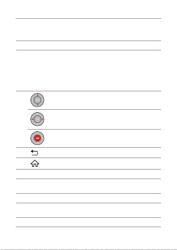
4
Move cursor up or down for selection.
Move cursor left or right for selection; or turn
page up and down when more than one page is
displayed.
Confirms a selection (or action) from a menu
list.
5 Return to the previous screen.
6 Press to navigate to the home screen.
7
Speakers
8
Foldable Stand
Flip out it to any angle and work comfortable at
your desk, or hang it on the steering wheel.
9
LCD Screen
Indicates the test result.
10
Charging LED
RED means Charging, and GREEN means
Fully Charged.
11
DC-IN Port
To connect to AC outlet for charging.
4
Page 13
LAUNCH X-431 PRO TP User Manual
12
Trigger antenna
Points it toward the sensor location to activate
the sensor.
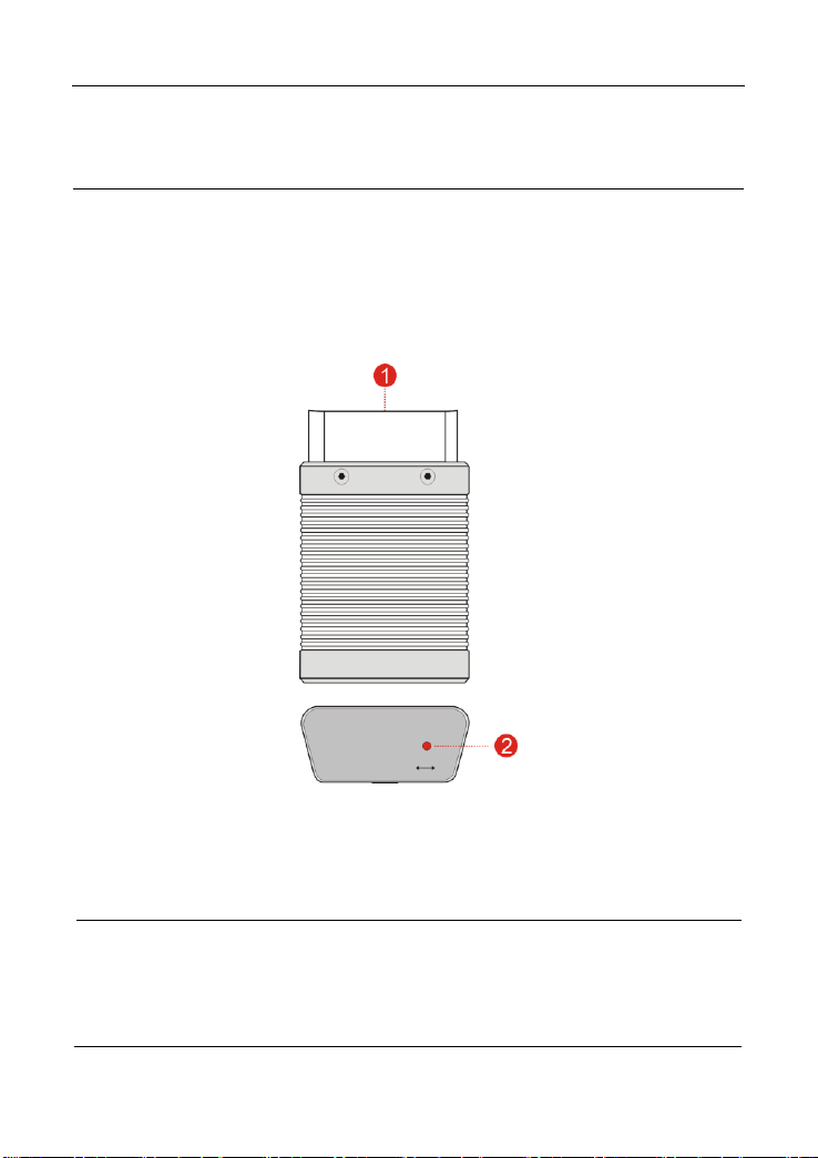
1
OBD-16 diagnostic
connector
To connect on vehicle’s OBD II DLC.
2
Mode indicator
It illuminates red when the VCI device is
connected to the vehicle’s DLC.
Blue indicates the VCI device is working in
wireless (BT) communication mode.
2.2 VCI Dongle (Only applies to 12V cars)
The VCI dongle works as a vehicle communication interface device, which is
used to connect to the vehicle’s DLC (Data Link Connector) socket directly or via
OBD II extension cable to read the vehicle data and then send it to the tablet via
Bluetooth.
Fig. 2-2 VCI device
5
Page 14

LAUNCH X-431 PRO TP User Manual
No.
Item
Descriptions
Qt.
1
X-431 PRO TP
tablet
Indicates the test result.
1
2
VCI dongle
Collects the vehicle data and sends it
to the tablet for analysis.
1
3
OBD II extension
cable
To connect the VCI dongle to the OBD
II vehicle’s DLC.
1
4
Password envelope
A piece of paper bearing the product
Serial Number and Activation Code for
product registration.
1
5
Power adaptors &
cable
For charging the tablet via AC outlet.
1
6
Cigarette lighter
cable
To supply power to the non-16pin
connector from the vehicle’s cigarette
lighter receptacle.
Optional
7
Battery clamps
cable
To supply power to the non-16pin
connector from the vehicle’s battery.
Optional
8
OBD I adaptor box
For connecting the VCI dongle and
non-16pin adaptor cable.
1
9
Non-16pin adaptor
cable kit
To connect to the vehicle equipped
with non-OBD II management system.
1
10
LAUNCH TPMS
sensor
8
2.3 Package List
Common accessories are same, but for different destinations, the accessories
(such as diagnostic software, testing connectors) may vary. Please consult from
the local agency or check the package list supplied with the tool together.
6
Page 15

LAUNCH X-431 PRO TP User Manual
3 Preparations
3.1 Charging the tablet
1. Insert one end of the included charging cable into the power adaptor.
2. Connect the other end into the DC-IN port of the tablet.
3. Plug the adaptor into AC outlet.
If appears on the screen, it indicates it is being charged. If the logo changes
into , it indicates that the battery is fully charged. Unplug the power adaptor
from the AC outlet.
3.2 Using your battery
If the battery remains unused for a long period of time or the battery is
completely discharged, it is normal that the tool will not power on while being
charged. Please charge it for a period of 5 minutes and then turn it on.
Please use the included power adaptor to charge your tool. No responsibility
can be assumed for any damage or loss caused as a result of using power
adaptors other than the one supplied.
While the tablet has low battery, a beep will sound. If it is very low, the tablet
will be switched off automatically.
3.3 Power on/off
3.3.1 Power on
Press [POWER] to turn the tool on.
*Note: If it is the first time you have used this tool or the tool remains idle for a long
period of time, the tool could fail to turn on. Please charge the tool for a minimum of 5
minutes and attempt to turn on again.
3.3.2 Power off
Press [POWER] for 3 seconds, an option menu will pop up on the screen. Tap
“Power off” to turn the tool off.
7
Page 16

LAUNCH X-431 PRO TP User Manual
Tap to navigate to the Home screen.
Tap it to display a list of applications that are currently running or
recently used.
Shows whether the VCI dongle is connected properly or not.
Tap it to capture the current screen and all captured screenshots
are stored in the Screenshots folder.
Tap it to return to the previous screen or exit the application.
3.4 Screen layout
There are the following on-screen buttons available on the bottom of the screen.
3.5 Adjust brightness
*Tips: Reducing the brightness of the screen is helpful to save the power of the tablet.
1. On the home screen, tap Tablet Settings -> Display -> Brightness level.
2. Drag the slider to adjust it.
3.6 Set standby time
If no activities are made within the defined standby period, the screen will be
locked automatically and the system enters sleep mode to save power.
1. On the home screen, tap Tablet Settings -> Display -> Sleep.
2. Choose the desired sleep time.
3.7 Network Setup
*Note: Once WLAN is set as ON, the tablet will consume more power. While WLAN
keeps unused, please turn it off to conserve battery power.
The tablet has a built-in Wi-Fi module that can be used to get online. Once
you’re online, you can register the tool, update the diagnostic software & APK,
surf the Internet and send email on your network.
3.7.1 Connect to a Wi-Fi network
1. On the home screen, tap Tablet Settings -> Wi-Fi.
8
Page 17

LAUNCH X-431 PRO TP User Manual
2. Tap or slide the Wi-Fi switch to ON, the tablet starts searching for all
available wireless LANs.
3. Choose the desired Wi-Fi access point / network,
If the network you chose is open, you can connect directly.
If the selected network is encrypted, you have to enter the right security
key (network password).
3.7.2 Disconnect from a Wi-Fi network
1. On the home screen, tap Tablet Settings -> Wi-Fi.
2. Tap the network with a Connected status, then tap “Disconnect”.
9
Page 18

LAUNCH X-431 PRO TP User Manual
Tap “Diagnose”
Select vehicle
(See Note*)
Select test system
Select test function
Select diagnostic
software version
Tap “Login” to
register
Is VCI
connector
activated ?
No
Download/Update
diagnostic software
Yes
…… (Refer to
Chapter 4.2)
Register & Activate
OK
4 Initial Use
4.1 Getting Started
For new users, please follow the operation chart shown in Fig. 4-1 to start using
this tool.
Note*: If “VIN Scan” or “Intelligent Diagnosis” function is performed, this step shall
not apply.
Fig. 4-1
10
Page 19

LAUNCH X-431 PRO TP User Manual
4.2 Register & Download Diagnostic Software
4.2.1 User registration
After the tablet is initialized, tap “Login” on the upper right corner of the screen, a
screen similar to the following appears.
Fig. 4-2
(If you are a new user, follow A to proceed.)
(If you have registered to be a member, go to B to login the system directly.)
(In case you forgot password, refer to C to reset a new password.)
A. If you are a new user, tap “New Registration” to enter registration page. See
Fig. 4-3.
Fig. 4-3
In Fig. 4-3, fill in the information in each field (Items with * must be filled). After
inputting, tap “Register”, a screen similar to the following will appear:
11
Page 20

LAUNCH X-431 PRO TP User Manual
Product SN
Activation code
Product SN
Fig. 4-4
In Fig. 4-4, input the Serial Number and Activation Code, which can be found in
the password envelope.
Fig. 4-5
Note: To exit and activate it later, tap “Skip”. In this case, you can activate your
connector by tapping “Activate VCI” in “User Info”. For details, please refer to Chapter
9.4.
Tap “Activate” to finish your registration. See Fig. 4-6.
12
Page 21

LAUNCH X-431 PRO TP User Manual
Name
Description
Intelligent
Diagnosis
This module allows you to obtain vehicle data from the
cloud server to perform quick test via reading VIN,
which provides a perfect solution to various defects
Fig. 4-6
To download the diagnostic software, tap “Yes” to enter the software update
screen.
Tap “No” to download and install it later.
On the update page, tap “Update” to start downloading. To pause downloading,
tap “Stop”. To resume it, tap “Continue”. Once download is complete, the system
will install the software package automatically.
*Note: In process of download, please make sure the tablet has a strong Wi-Fi signal. It
may take several minutes to finish it, please be patient to wait.
B. If you have registered to be a member, input your name and password, and
then tap the “Login” button to enter the main menu screen directly.
*Note: The tablet has an auto-save function. Once the username and password are
correctly entered, the system will automatically store it. Next time you login the system,
you will not be asked to input the account manually.
C. If you forgot the password, tap “Retrieve password” and then follow on-screen
instructions to set a new password.
4.2.2 Job menu
It mainly includes the following items:
13
Page 22

LAUNCH X-431 PRO TP User Manual
resulting from step-by-step menu selection. In addition,
user can also check the historical repair records online
through this module.
Local Diagnosis
To diagnose a vehicle manually.
TPMS
This module provides the ability to activate most
OEM/Universal TPMS sensors, and allows users to
reprogram sensor IDs, retrieve/clear TPMS DTCs and
sensor relearning, helping technicians quickly find out
faulty TPMS and turn off MILs.
Remote Diagnosis
This option aims to help repair shops or technicians
launch instant messaging and remote diagnosis,
making the repair job getting fixed faster.
Software Update
To update vehicle diagnostic software and APK.
Diagnostic History
Generally once a vehicle diagnosis is performed, the
tablet will automatically save every details of diagnostic
process. This function provides a quick access to the
tested vehicles. Test can be resumed from the last
operation, without starting from scratch.
Reset
To perform all kinds of common repair & maintenance
items, including electronic throttle position reset, ABS
bleeding, oil lamp reset etc.
Feedback
To feed back the recent 20 diagnostic logs to us for
issue analysis.
Maintenance Help
Abundant maintenance data are available, which helps
repair professionals diagnose and repair vehicles
efficiently, accurately and profitably.
User Info
To manage VCI, my reports, diagnostic software,
change password, configure wireless Wi-Fi printer and
system settings and logout etc.
Vehicle Coverage
To view all the vehicle models that the tablet covers.
Tablet Setting
Configures the system settings of the tablet.
Other Modules
Includes How-To videos, product manual and FAQ.
14
Page 23

LAUNCH X-431 PRO TP User Manual
1
VIN Scan button: Tap it to input the Vehicle Identification Number (VIN)
code of your vehicle. This function does not apply to the commercial
vehicles.
*Note: Before using this function, the corresponding diagnostic software and
Auto search file need to be downloaded on your tool first while downloading
the diagnostic software.
2
All Tab: Displays all the vehicle makes in the vehicle menu.
3
Common Tab: Displays all the commonly used vehicle makes.
4
Vehicle region buttons: Tap different buttons to switch to corresponding
vehicles.
5
Search bar: Enables you to use the virtual keyboard to quickly locate
the vehicle model. Input the desired vehicle model to start searching.
1 2 3 4 5
4.2.3 Vehicle menu layout
After downloading the diagnostic software, go to “Local Diagnosis” to check if all
software are completely downloaded and installed.
Tap “Local Diagnosis”, a screen similar to the following figure appears:
Fig. 4-7
4.2.4 Diagnostics toolbar
The diagnostics toolbar contains a number of buttons that allow you to print the
displayed data or make other controls. It is displayed on the upper right corner of
the screen and goes through the whole diagnostic session. The table below
provides a brief description for the operations of the diagnostics toolbar buttons:
Fig. 4-8
15
Page 24

LAUNCH X-431 PRO TP User Manual
Name
Button
Description
Home
Returns to Job menu screen.
Print
Tap to print the current screen. To perform
printing, you need to purchase an extra Wi-Fi
printer manufactured by LAUNCH separately
and then properly configure the wireless printer
following the steps described in Chapter 9.8.3.
Exit
To exit the diagnostic application.
4.3 Connections
4.3.1 Preparation
Normal testing conditions
Turn on the vehicle power supply.
Throttle should be in a closed position.
4.3.2 DLC location
The DLC (Data Link Connector) is typically a standard 16 pin connector where
diagnostic code readers interface with the vehicle’s on-board computer. The
DLC is usually located 12 inches from the center of the instrument panel (dash),
under or around the driver’s side for most vehicles. If Data Link Connector is not
located under dashboard, a label should be there telling location. For some
Asian and European vehicles, the DLC is located behind the ashtray and the
ashtray must be removed to access the connector. If the DLC cannot be found,
refer to the vehicle’s service manual for the location.
16
Page 25

LAUNCH X-431 PRO TP User Manual
Fig. 4-9
4.3.3 Vehicle connection
The method used to connect the diagnostic connector to a vehicle’s DLC
depends on the vehicle’s configuration as follows:
A vehicle equipped with an OBD II management system supplies both
communication and 12V power through a standardized DLC.
A vehicle not equipped with an OBD II management system supplies
communication through a DLC connection, and in some cases supplies 12V
power through the cigarette lighter receptacle or a connection to the vehicle
battery.
Follow the steps mentioned below to connect OBD II vehicle:
1. Locate vehicle’s DLC socket.
2. Plug the VCI dongle into the vehicle’s DLC s ocket (It is suggested to use the
OBD II extension cable to connect the VCI dongle and DLC).
3. Choose one of the two ways to obtain power from:
A. Power adaptor: Connect one end of the included power adaptor to DC IN
port of the tablet, and the other end to AC outlet.
B. Internal battery pack
For non-OBDII vehicle, proceed as follows:
1. Locate vehicle’s DLC socket.
2. Select the corresponding non-16pin connector.
3. Plug the non-16pin end of the connector into the DLC socket, and the other
end to the OBD I adaptor, and then tighten the captive screws.
4. Connect the other end of the adaptor to the included VCI dongle.
5. To supply power to OBD I adaptor from:
A. Cigarette Lighter Cable (optional): Connect one end of the cigarette lighter
cable to vehicle’s cigarette lighter receptacle, and the other end to the power
jack of OBD I adaptor.
17
Page 26

LAUNCH X-431 PRO TP User Manual
Fig. 4-10
B. Battery Clamps Cable (optional): Connect one end of the battery clamps
cable to vehicle’s battery, and the other end to the power jack of OBD I
adaptor.
Fig. 4-11
4.4 Communication Setup
There are two kinds of ways available for the tablet to pair with the VCI dongle.
1. Plug the VCI dongle into the vehicle’s DLC directly (or using the OBD II
extension cable). The power LED of the VCI dongle lights up.
2. Enter Bluetooth setting screen by tapping “Tablet Settings” --> “Bluetooth”,
slide the Bluetooth switch to ON and the tablet starts searching for all
available Bluetooth device.
3. Tap the desired VCI dongle to pair and match. By default, the Bluetooth ID of
the VCI dongle is 98********00 (where ******** stands for 8 digits.).
4. If the Bluetooth pair request pops up on the screen, enter the request pin
code (default code: 0000 or 1234).
5. Once the VCI dongle is paired with the tablet, it will be shown under the
paired device tab.
Note: In case no Bluetooth setting is done before diagnostic software is launched, you
can also configure it in process of vehicle diagnosis.
18
Page 27

LAUNCH X-431 PRO TP User Manual
5 Diagnosis
5.1 Intelligent Diagnosis
Through simple Bluetooth communication between the tablet and VCI dongle,
you can easily get the VIN (Vehicle Identification Number) information of the
currently identified vehicle. Once the VIN is successfully identified, the system
will retrieve it from the remote server and then guide you to vehicle information
page without step-by-step manual menu selection.
The vehicle information page lists all historical diagnostic records of the vehicle,
which lets the technician have a total command of the vehicle faults. In addition,
a quick dial to local diagnosis and diagnostic function are also available on this
page for reducing the roundabout time and increasing productivity.
Notes:
• Before using this function, please make sure the VCI dongle is properly connected
to the vehicle’s DLC. For detailed connection, see Chapter 4.3.3 “Vehicle
Connection”.
• A stable network connection is required for this function.
Follow the steps below to proceed.
Tap “Intelligent Diagnosis” on the Job menu screen to start scanning.
Note: If the VCI dongle is not paired up with the tablet before doing this step, a prompt
message box will appear:
Fig. 5-1
*Note: If the VCI connector is not paired up with the tablet before doing this step, a
prompt message box will appear:
19
Page 28

LAUNCH X-431 PRO TP User Manual
Fig. 5-2
Check all the possible reasons of Bluetooth connection failure carefully, and then tap
“ok”.
Fig. 5-3
If the VCI dongle was once used with other devices, you need to cancel the pairing of
the connector first via either one of the following ways:
• On the Android’s home screen, tap “Tablet Settings” -> “Bluetooth” -> Choose the
desired VCI dongle from the Paired list. Tap “ ”, and then tap “FORGET” to
unpair it.
• Tap “User Info” -> “VCI Management” -> Tap “Deactivate matching”.
In Fig. 5-3, tap “Scan” to start searching for the VCI dongle and pairing up with it.
20
Page 29

LAUNCH X-431 PRO TP User Manual
Fig. 5-4
A. If the VIN can be found from the remote server database, a screen similar to
Fig. 5-5 displays:
Fig. 5-5
• Tap “Diagnostic” to start a new diagnostic session.
• Tap “Maintenance record” to view its historical repair record. If there are
records available, it will be listed on the screen in sequence of date. If no
records exist, the screen will show “No Record”.
21
Page 30

LAUNCH X-431 PRO TP User Manual
Fig. 5-6
• Tap “View record” to view the details of the current diagnostic report.
• To perform other functions, tap “Quick access” to directly go to the function
selection screen. Choose the desired one to start a new diagnostic
session.
B. If the tablet failed to access the VIN information, the screen will enter the VIN
manual input mode.
Input the VIN and tap “OK” to start scanning. If the VIN exists on the remote
server, the system will enter the vehicle information screen. See Fig. 5-4.
Notes:
The most recognizable location for this VIN is in the top left corner on the
vehicle’s dashboard. Other locations include the driver’s door or post, and the
firewall under the hood.
In general, vehicle identification numbers are standardized - all contain 17
characters. VIN characters may be capital letters A through Z and numbers 1
through 0; however, the letters I, O and Q are never used in order to avoid
mistakes of misreading. No signs or spaces are allowed in the VIN.
5.2 Local Diagnosis
Tap “Local Diagnosis” to enter the vehicle selection page.
VIN Scan and manual diagnosis are available for your selection.
A. VIN Scan
While performing VIN Scan, user needs to enter the vehicle VIN manually.
22
Page 31

LAUNCH X-431 PRO TP User Manual
Fig. 5-7
After the VIN is successfully decoded, the vehicle information will be displayed
on the screen. Tap “Next” to navigate to the diagnostic function selection screen.
B. Manual Selection
Tap a corresponding diagnostic software logo, and then follow the on-screen
instruction to access the diagnostic software.
Take Demo as an example to demonstrate how to diagnose a vehicle.
1). Select diagnostic software version: Tap the “DEMO” to go to Step 2. (Note: If
more than one version is available on this tablet, it will be listed on the screen.)
Fig. 5-8
On-screen Buttons:
Vehicle Coverage: Tap to view the vehicle models that the current diagnostic
software covers.
What’s New: Tap to view the optimized items and enhancements.
Software introduction: Tap to check the software function list.
23
Page 32

LAUNCH X-431 PRO TP User Manual
Note: Tap to read some precautions on using the current diagnostic software.
Search Bluetooth: Tap to search for the available VCI Bluetooth connector.
Notes:
• No Bluetooth connection is required for DEMO program.
• If a vehicle is tested and no Bluetooth connection is made before diagnosis, tap
“Search Bluetooth”, a dialog box similar to the following appears:
Fig. 5-9
Tap “Scan” to start searching for the VCI dongle. Once it is found, tap it to start
pairing.
If the tablet has paired with the VCI dongle, it will enter Step 2 directly.
Confirm: Tap it to go to next step.
2). Select test item: Select the desired test item to proceed.
Fig. 5-10
5.2.1 Health Report (Quick Test)
This function varies from vehicle to vehicle. It enables you to quickly access all
the electronic control units of the vehicle and generate a detailed report about
24
Page 33

LAUNCH X-431 PRO TP User Manual
vehicle health.
Tap “Health Report”, the system start scanning the ECUs.
Once the scanning is complete, a screen similar to the following appears:
Fig. 5-11
In Fig. 5-11, the tested system with fault code appears in red and the system
with OK displays in black (normally).
On-screen Buttons:
Enter: Tap to enter the diagnostic menus of the current system.
Search: Tap to launch the browser to search for more detailed information
about the current DTC online.
Clear DTC: Tap to clear the existing diagnostic trouble codes.
*Note: Clearing DTCs does not fix the problem(s) that caused the code(s) to be set. If
proper repairs to correct the problem that caused the code(s) to be set are not made,
the code(s) will appear again and the check engine light will illuminate as soon as the
problem that cause the DTC to set manifests itself.
Report: Tap to save it as a diagnostic report.
25
Page 34

LAUNCH X-431 PRO TP User Manual
Fig. 5-12
Input the required information, and then tap “Confirm” to save it.
Alternatively you can also set the workshop information in “User Info” ->
“Settings” -> “Print Information”.
*Note: Configured information is automatically generated each time the diagnostic
report is saved. All vehicle and workshop information will be appended as tags on the
diagnostic report.
To skip the workshop information, tap “Skip” to go to the next step.
All reports are saved under the tab “Diagnostic Report” in “My Report” from
“User Info” menu. For details on report operations, please refer to Chapter 9.1
“My Report”.
5.2.2 System Scan
This option allows you to quickly scan which systems are installed on the
vehicle.
In Fig. 5-10, tap “System Scan”, the system start scanning the systems. Once
the scanning is complete, the screen will display the result.
26
Page 35

LAUNCH X-431 PRO TP User Manual
Fig. 5-13
Tap the desired system to advance to the test function selection page. For
detailed operations on test function, please refer to Chapter 5.2.3.
5.2.3 System Selection
This option allows you manually select the test system and function step by step.
In Fig. 5-10, tap “System Selection”, the screen displays as follows:
Fig. 5-14
Swipe the screen from the bottom to view the vehicle system on the next page.
Tap the desired system (take “ECM” for example) to jump to the test function
page.
27
Page 36

LAUNCH X-431 PRO TP User Manual
Fig. 5-15
Note: Different vehicle has different diagnostic menus.
A. Version Information
This function is used to read the version information of system mode, vehicle
VIN, software and ECU.
B. Read Fault Code
This function displays the detailed information of DTC records retrieved from the
vehicle’s control system.
*Notes:
• Diagnostic Trouble Codes or Fault Codes can be used to identify which engine
systems or components that are malfunctioning. Never replace a part based only on
the DTC definition. Retrieving and using DTCs for troubleshooting vehicle
operation is only one part of an overall diagnostic strategy. Follow testing
procedures (in vehicle’s service manual), instructions and flowcharts to confirm the
locations of the problem.
• Retrieving and using DTCs for troubleshooting vehicle operation is only one part of
an overall diagnostic strategy. Never replace a part based only on the DTC
definition. Each DTC has a set of testing procedures, instructions and flow charts
that must be followed to confirm the location of the problem. This information can
be found in the vehicle’s service manual.
In Fig. 5-15, tap “Read DTC”, the screen will display the diagnostic result.
28
Page 37

LAUNCH X-431 PRO TP User Manual
Fig. 5-16
On-screen Buttons:
Freeze Frame: When an emission-related fault occurs, certain vehicle
conditions are recorded by the on-board computer. This information is referred
to as freeze frame data. Freeze frame data includes a snapshot of critical
parameter values at the time the DTC is set.
Help: Tap to view the help information.
Code Search: Tap it to search for more information about the current DTC
online.
Report: To save the current data in text format. All reports are saved under the
tab “Diagnostic Report” in “My Report” from “User Info” menu. For details on
report operations, please refer to Chapter 9.1 “My Report”.
C. Clear Fault Memory
After reading the retrieved codes from the vehicle and certain repairs have been
carried out, you can use this function to erase the codes from the vehicle. Before
performing this function, please be sure the vehicle’s ignition key is in the ON
position with the engine off.
Clearing DTCs does not fix the problem(s) that caused the code(s) to be set. If
proper repairs to correct the problem that caused the code(s) to be set are not
made, the code(s) will appear again and the check engine light will illuminate as
soon as the problem that cause the DTC to set manifests itself.
In Fig. 5-15, tap “Clear Fault Memory”, a confirmation dialog box pops up on the
screen.
29
Page 38

LAUNCH X-431 PRO TP User Manual
Fig. 5-17
Tap “Yes”, the system will automatically delete the currently existing trouble
code.
Note: The trouble code will not disappear until the trouble was completely cleared.
D. Read Data Stream
This option lets you view and capture (record) real-time Live Data. This data
including current operating status for parameters and/or sensor information can
provide insight on overall vehicle performance. It can also be used to guide
vehicle repair.
*Note: If you must drive the vehicle in order to perform a troubleshooting procedure,
ALWAYS have a second person help you. Trying to drive and operate the diagnostic
tool at the same time is dangerous, and could cause a serious traffic accident.
In Fig. 5-15, tap “Read Data Stream”, the system will display data stream items.
On-screen Buttons:
Fig. 5-18
30
Page 39

LAUNCH X-431 PRO TP User Manual
Select Page: Tap it to select all items of the current page.
Select All: Tap it to select all items of the current page. To select certain data
stream item, just check the box before the item name.
Unselect: Tap it to deselect all data stream items.
OK: Tap it to confirm and jump to the next step.
After selecting the desired items, tap “Confirm” to enter the data stream reading
page.
Fig. 5-19
Notes:
1. If the value of the data stream item is out of the range of the standard (reference)
value, the whole line will display in red. If it complies with the reference value, it
displays in blue (normal mode).
2. The indicator 1/X shown on the bottom of the screen stands for the current
page/total page number. Swipe the screen from the right/left to advance/return to the
next/previous page.
There are 3 types of display modes available for data viewing, allowing you to
view various types of parameters in the most suitable way.
Value – this is the default mode which displays the parameters in texts and
shows in list format.
Graph – displays the parameters in waveform graphs.
Combine – this option is mostly used in graph merge status for data
comparison. In this case, different items are marked in different colors.
On-screen Buttons:
Graph(Single): Tap it to view the waveform.
31
Page 40

LAUNCH X-431 PRO TP User Manual
Fig. 5-20
Compare Sample: Tap it to select the sample DS file, the values you
customized and saved in process of DS sampling will be imported into the
“Standard Range”(See below) column for your comparison.
*Note: Before executing this function, you have to sample the values of data stream
items and save it as a sample DS file.
Fig. 5-21
Save Sample: This item enables you to customize the standard range of live
data stream items and save it as DS sample file. Each time you run the data
stream items, you can call out the corresponding sample data to overwrite the
current standard range.
Tap it to start recording the sample data (*Only data stream items with
32
Page 41

LAUNCH X-431 PRO TP User Manual
measurement units will be recorded), and the screen displays as below:
Fig. 5-22
Once recording is complete, tap to stop it and navigate to the data revision
screen.
Fig. 5-23
Tap the Min./Max. value to change it. After modifying all desired items, tap
“Save” to save it as a sample DS file. All DS files are stored under the “Data
Stream Sample” file in “User Info”.
Graph: Tap it to view the waveform.
33
Page 42

LAUNCH X-431 PRO TP User Manual
Fig. 5-24
• Combine: This option is mostly used in graph merge status for data
comparison. In this case, different items are marked in different colors
(maximum 4 items can be displayed on the same screen simultaneously).
If the graph is more than one page, swipe the screen from the left to jump
to the next page.
Fig. 5-25
• Value: Switches the current graph display mode to Value display mode.
• Report: To save the current data in text format. All reports are saved under
the tab “Diagnostic Report” in “My Report” from “User Info” menu.
• Record: Tap to start recording diagnostic data for future playback and
analysis. The file is stored in “My Report” under “User Info” menu.
34
Page 43

LAUNCH X-431 PRO TP User Manual
Report: To save the current data in text format. All reports are saved under the
“Diagnostic Report” tab of “My Report” in “User Info”. For details on report
operations, please refer to Chapter 9.1 “My Report”.
Record: Tap to start recording diagnostic data for future playback and analysis.
The saved file follows the naming rule: It begins with vehicle type, and then the
record starting time and ends with .x431 (To differentiate between files, please
configure the accurate system time). The file is stored in “My Report” under
“User Info” menu.
Fig. 5-26
Help: Tap to view the help information.
E. Actuation Test
This option is used to access vehicle-specific subsystem and component tests.
Available test vary by vehicle manufacturer, year, and model.
During the actuation test, the tablet outputs commands to the ECU in order to
drive the actuators, and then determines the integrity of the system or parts by
reading the ECU data, or by monitoring the operation of the actuators, such as
switching a injector between two operating states.
In Fig. 5-15, tap “Actuation Test”, the system will display as follows:
35
Page 44

LAUNCH X-431 PRO TP User Manual
4
5 6 3 2 1
Fig. 5-27
Simply follow the on-screen instructions and make appropriate selections to
complete the test. Each time when an operation is successfully executed,
“Completed” displays.
5.3 Remote Diagnosis
This option aims to help repair shops or technicians launch instant messaging
and remote diagnosis, making the repair job getting fixed faster.
Tap “Remote Diagnosis” on the Job menu, the screen appears blank by default.
5.3.1 Interface Layout
Fig. 5-28
36
Page 45

LAUNCH X-431 PRO TP User Manual
1
Home button
Tap it to navigate to the Job menu screen.
2
Search bar
Directly input the username of the tablet to start
searching, and then tap the desired one to add it into your
friend list.
3
Friend list
display area
By default it appears blank.
3
Message tab
Once an incoming message reaches, a red dot will appear
on the upper right corner of the tab.
4
Contact tab
Tap to enter the friend list.
5
WEB Remote
switch
Tap to slide the switch to ON, the tablet keeps online and
becomes accessible on the web client. In this case, inform
the technician of your product S/N, and he/she will control
your tablet remotely.
5.3.2 Add Friends
Tap “Contact” to enter the contact page. By default it appears blank.
In the search bar, input the partner’s username and tap “Search” button next to
the search bar to starts searching from Launch’s golo business database.
The partner must be the users who have registered their Launch’s diagnostic
tools. They may be the following:
Workshop
Technician
golo users
Once the result matches the keyword, a screen similar to the following will
appear:
*Note: Here you can tap “Remote Diagnose” to launch remote diagnostics directly or
choose to add the partner into the Contacts list.
37
Page 46

LAUNCH X-431 PRO TP User Manual
Fig. 5-29
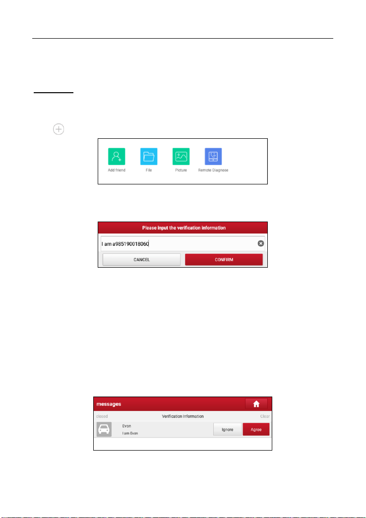
There are two methods available for you to add the partner into the Contacts list.
Method 1:
Tap the desired partner’s avatar from the list, the following screen appears:
*Tips: If you intend to chat with the partner, just tap the desired partner’s name.
Fig. 5-30
Tap “Add friend”, a dialog box pops up:
38
Page 47
LAUNCH X-431 PRO TP User Manual
Fig. 5-31
Tap “CONFIRM” to send your request.
Method 2:
Tap the desired partner’s name from the list to enter into the instant messaging
mode.
Tap to call out more function options.
Fig. 5-32
Tap “Add friend”, a dialog box pops up:
Fig. 5-33
Tap “CONFIRM” to send your request.
Once the partner receives the request, a beep will sound. Tap the “Message”
tab:
• Once the partner agreed your request, he/she will automatically be listed in
the Contact tab.
• If a technician sent you a friend request, you can tap “Agree” to confirm and
his/her name will appear in the friend list (Contact). Or tap “Ignore” to ignore
this request.
Fig. 5-34
39
Page 48

LAUNCH X-431 PRO TP User Manual
5.3.3 Start Instant Messaging
Note: The I/M (Instant Messaging) function is open to all users who had Launch’s
diagnostic tool equipped with this module.
After adding your friends, tap the desired one’s photo to enter a screen similar to
the following:
Fig. 5-35
Tap the input field and use the on-screen keyboard to enter the text message,
and then tap “Send” to send it.
Tap to send the emoj.
Tap to call out more function options.
Tap “Clear” to delete all the partner’s dialog logs.
Tap “Close” to close the current dialog.
Fig. 5-36
File: Choose diagnostic reports or local files to send.
Picture: Choose screenshots or pictures to send.
Remote Diagnostic: To start a remote diagnostic session. For details, refer to
40
Page 49

LAUNCH X-431 PRO TP User Manual
Actions
Results
Request control
remote device
Request to control the partner’s device remotely to
help him diagnose the vehicle.
*Notes:
Remote diagnosis has the same diagnostic steps as
manual diagnosis.
Once vehicle diagnosis is complete, a report will be
created. Input your comments on this report, and then
tap “Send Report” to send it to the partner.
Chapter 5.3.4.
5.3.4 Launch Remote Diagnosis (Device-To-Device)
The tablet is allowed to launch remote diagnosis with other diagnostic tools
(including but not limited to the X-431 PRO TP) of Launch family, which are
equipped with this module.
* Note: Before performing this operation, please make sure the following no matter
which side sends the remote request:
Turn on the vehicle power supply.
Throttle should be in a closed position.
The VCI dongle should be properly connected to the vehicle’s DLC and a successful
communication is required.
In Fig. 5-36, tap “Remote Diagnostic”, a pull-down menu including the following
options appears:
Fig. 5-37
These options are defined as follows:
41
Page 50

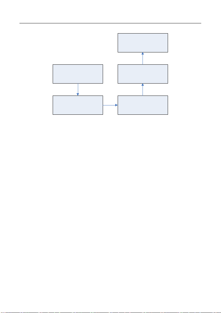
LAUNCH X-431 PRO TP User Manual
Tap “Request control remote device”
Wait for partner’s confirmation
Start connecting after request confirmed
Start Diagnosis
Generate diagnostic report
Invite remote
diagnostic assistant
If you need support, just use this option to invite a
technician to perform a remote control on your tool.
*Notes:
Remote diagnosis has the same diagnostic steps as
manual diagnosis.
Once you received the report from the partner, tap
“View Report” to view details. All diagnostic reports
are saved under the “Remote Diagnostic Reports” tab
of “My Reports” in “User Info”.
42
Page 51

LAUNCH X-431 PRO TP User Manual
Tap “Invite remote diagnostic assistant”
Choose the desired diagnostic software
Wait for partner’s confirmation
Start connecting after request confirmed
Start Diagnosis
Generate diagnostic report
Cancel
To cancel this operation.
5.3.5 Launch Remote Diagnosis (Device-To-PC)
Except that the remote diagnosis can be done between different Launch’s
diagnostic tools that come loaded with the module, user also can ask for remote
control from PC client technician.
43
Page 52

LAUNCH X-431 PRO TP User Manual
Slide the switch to ON
Notify the partner of the remote diagnostic web link
Input the partner’s official account and password
Input the Serial Number of your handset
Start Diagnosis
Generate diagnostic report
Fig. 5-38
Tap the “Web Remote” tab, the screen displays as follows:
44
Page 53

LAUNCH X-431 PRO TP User Manual
Fig. 5-39
1. Slide the switch “Allow device to be connected to the WEB client remote
diagnostic device” to ON so that the partner can find and connect to this
device while using the PC.
2. Notify the partner of the PC client website http://remote.x431.com/cn/. When
the partner accesses the link, the PC displays as below:
*Note: Before processing remote diagnosis, please make sure the tablet is properly
connected to the vehicle.
Fig. 5-40
3. Tell the partner to input his own official technician account and password, and
45
Page 54

LAUNCH X-431 PRO TP User Manual
then tap “Login” to navigate to the following figure.
Fig. 5-41
4. Tell the partner to check the box “Series number” and enter the Serial
Number provided by you, and then tap “Start remote diagnosis” to control
your device remotely.
In process of remote diagnosis, please note the following things:
1) You are not suggested to execute any actions.
2) The partner is not allowed to save any diagnostic reports or records on
your tablet.
The operations in remote diagnosis are same as those in local diagnosis. Once
the session is complete, a remote diagnostic report will be automatically
generated.
5.4 How to view diagnostic history?
Generally once a vehicle diagnosis is performed, the tablet will record the every
details of diagnostic process. The History function provides direct access to the
previously tested vehicles and users can resume from the last operation, without
46
Page 55

LAUNCH X-431 PRO TP User Manual
the necessity of starting from scratch.
Tap “Diagnostic History” on the Job menu screen, all diagnostic records will be
listed on the screen in date sequence.
• Tap certain vehicle model to view the details of the last diagnostic report.
• To delete certain diagnostic history, select it and then tap “Delete”. To
delete all historical records, tap “Select All” and then tap “Delete”.
• Tap “Quick access” to directly navigate to the function selection page of
last diagnostic operation. Choose the desired option to proceed.
5.5 How to feedback diagnostic logs?
This item allows you to feedback your diagnostic problems to us for analysis and
troubleshooting.
Tap “Feedback”, the following 3 options will be displayed on the left column of
the screen.
A. Feedback
Tap a tested vehicle model to enter the feedback screen.
1) Tap “Choose File” to open the target folder and choose the desired diagnostic
logs.
2) Choose the failure type and fill in the detailed failure description in the blank
text box and telephone or email address. After inputting, tap “Submit Result”
to send it to us.
B. History
Tap it to view all diagnostic feedback records. Different process states are
marked with different colors.
C. Offline list
Tap it to display all diagnostic feedback logs which have not been submitted
successfully due to network failure. Once the handset gets a stable network
signal, it will be uploaded to the remote server automatically.
47
Page 56

LAUNCH X-431 PRO TP User Manual
6 Special (Reset) Function
In addition to amazing & powerful diagnostic function, the tablet also features
various service functions. The most commonly performed service functions
contain:
Oil Reset Service
Electronic Parking Brake Reset
Steering Angle Calibration
ABS Bleeding
TPMS (Tire Pressure Monitor System) Reset
Gear Learning
IMMO Service
Injector Coding
Battery Maintenance System
Diesel Particulate Filter (DPF) Regeneration
Electronic Throttle Position Reset
There are two methods to reset service lamp: Manual reset or Auto reset. Auto
reset follows the principle of sending command from the tool to vehicle’s ECU to
do resetting. While using manual reset, users just follow the on-screen
instructions to select appropriate execution options, enter correct data or values,
and perform necessary actions, the system will guide you through the complete
performance for various service operations.
48
Page 57
LAUNCH X-431 PRO TP User Manual
Select “Reset”
Select the desired reset
item (e.g. oil lamp reset
etc.)
Select the car brand
Select the service mode
(The available mode varies
from vehicle to vehicle)
Follow the instructions
on the screen to operate
Figure 6-1
6.1 Oil Reset Service
This function allows you to perform reset for the engine oil life system, which
calculates an optimal oil life change interval depending on the vehicle driving
conditions and climate.
This function can be performed in the following cases:
1. If the service lamp is on, you must provide service for the car. After service,
you need to reset the driving mileage or driving time so that the service lamp
turns off and the system enables the new service cycle.
2. After changing engine oil or electric appliances that monitor oil life, you need
to reset the service lamp.
6.2 Electronic Parking Brake Reset
1. If the brake pad wears the brake pad sense line, the brake pad sense line
sends a signal sense line to the on-board computer to replace the brake pad.
After replacing the brake pad, you must reset the brake pad. Otherwise, the
car alarms.
2. Reset must be performed in the following cases:
a) The brake pad and brake pad wear sensor are replaced.
b) The brake pad indicator lamp is on.
c) The brake pad sensor circuit is short, which is recovered.
d) The servo motor is replaced.
49
Page 58

LAUNCH X-431 PRO TP User Manual
6.3 Steering Angle Calibration
To reset the steering angle, first find the relative zero point position for the car to
drive in straight line. Taking this position as reference, the ECU can calculate the
accurate angle for left and right steering.
After replacing the steering angle position sensor, replacing steering mechanical
parts (such as steering gearbox, steering column, end tie rod, steering knuckle),
performing four-wheel alignment, or recovering car body, you must reset the
steering angle.
6.4 ABS Bleeding
This function allows you to perform various bi-directional tests to check the
operating conditions of Anti-lock Braking System (ABS).
1. When the ABS contains air, the ABS bleeding function must be performed to
bleed the brake system to restore ABS brake sensitivity.
2. If the ABS computer, ABS pump, brake master cylinder, brake cylinder, brake
line, or brake fluid is replaced, the ABS bleeding function must be performed
to bleed the ABS.
6.5 Tire Pressure Monitor System Reset
This function allows you to quickly look up the tire sensor IDs from the vehicle’s
ECU, as well as to perform TPMS replacement and sensor test.
1. After the tire pressure MIL turns on and maintenance is performed, the tire
pressure resetting function must be performed to reset tire pressure and turn
off the tire pressure MIL.
2. Tire pressure resetting must be performed after maintenance is performed in
the following cases: tire pressure is too low, tire leaks, tire pressure
monitoring device is replaced or installed, tire is replaced, tire pressure sensor
is damaged, and tire is replaced for the car with tire pressure monitoring
function.
6.6 Gear Learning
The crankshaft position sensor learns crankshaft tooth machining tolerance and
saves to the computer to more accurately diagnose engine misfires. If tooth
learning is not performed for a car equipped with Delphi engine, the MIL turns on
after the engine is started. The diagnostic device detects the DTC P1336 'tooth
50
Page 59

LAUNCH X-431 PRO TP User Manual
not learned'. In this case, you must use the diagnostic device to perform tooth
learning for the car. After tooth learning is successful, the MIL turns off.
After the engine ECU, crankshaft position sensor, or crankshaft flywheel is
replaced, or the DTC 'tooth not learned' is present, tooth learning must be
performed.
6.7 IMMO Service
An immobilizer is an anti-theft mechanism that prevents a vehicle’s engine from
starting unless the correct ignition key or other device is present. Most new
vehicles have an immobilizer as standard equipment. An important advantage of
this system is that it doesn’t require the car owner to activate it since it operates
automatically. An immobilizer is considered as providing much more effective
anti-theft protection than an audible alarm alone.
As an anti-theft device, an immobilizer disables one of the systems needed to
start a car’s engine, usually the ignition or the fuel supply. This is accomplished
by radio frequency identification between a transponder in the ignition key and a
device called a radio frequency reader in the steering column. When the key is
placed in the ignition, the transponder sends a signal with a unique identification
code to the reader, which relays it to a receiver in the vehicle’s computer control
module. If the code is correct, the computer allows the fuel supply and ignition
systems to operate and start the car. If the code is incorrect or absent, the
computer disables the system, and the car will be unable to start until the correct
key is placed in the ignition.
To prevent the car being used by unauthorized keys, the anti-theft key matching
function must be performed so that the immobilizer control system on the car
identifies and authorizes remote control keys to normally use the car.
When the ignition switch key, ignition switch, combined instrument panel, ECU,
BCM, or remote control battery is replaced, anti-theft key matching must be
performed.
6.8 Injector Coding
Write injector actual code or rewrite code in the ECU to the injector code of the
corresponding cylinder so as to more accurately control or correct cylinder
injection quantity.
After the ECU or injector is replaced, injector code of each cylinder must be
confirmed or re-coded so that the cylinder can better identify injectors to
accurately control fuel injection.
51
Page 60

LAUNCH X-431 PRO TP User Manual
6.9 Battery Maintenance System Reset
This function enables you to perform a resetting operation on the monitoring unit
of vehicle battery, in which the original low battery fault information will be
cleared and battery matching will be done.
Battery matching must be performed in the following cases:
a) Main battery is replaced. Battery matching must be performed to clear
original low battery information and prevent the related control module from
detecting false information. If the related control module detects false
information, it will invalidate some electric auxiliary functions, such as
automatic start & stop function, sunroof without one-key trigger function,
power window without automatic function.
b) Battery monitoring sensor. Battery matching is performed to re-match the
control module and motoring sensor to detect battery power usage more
accurately, which can avoid an error message displaying on the instrument
panel.
6.10 Diesel Particulate Filter (DPF) Regeneration
DPF regeneration is used to clear PM (Particulate Matter) from the DPF filter
through continuous combustion oxidation mode (such as high temperature
heating combustion, fuel additive or catalyst reduce PM ignition combustion) to
stabilize the filter performance.
DPF regeneration may be performed in the following cases:
a) The exhaust back pressure sensor is replaced.
b) The PM trap is removed or replaced.
c) The fuel additive nozzle is removed or replaced.
d) The catalytic oxidizer is removed or replaced.
e) The DPF regeneration MIL is on and maintenance is performed.
f) The DPF regeneration control module is replaced.
6.11 Electronic Throttle Position Reset
This function enables you to make initial settings to throttle actuators and returns
the “learned” values stored on ECU to the default state. Doing so can accurately
control the actions of regulating throttle (or idle engine) to adjust the amount of
air intake.
52
Page 61
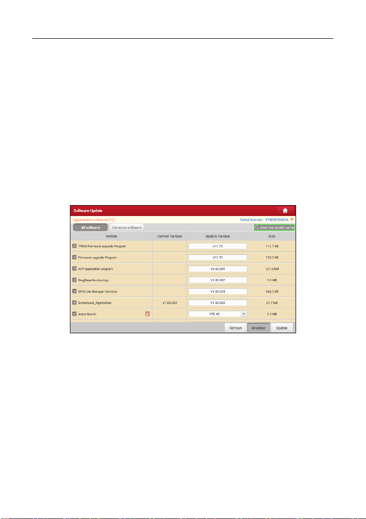
LAUNCH X-431 PRO TP User Manual
7 Software Update
This module allows you to update the diagnostic software & App and set
frequently used software.
If you did not download the software in process of product registration or a
pop-up message prompting you that some new software can be updated, you
may use this option to download it or keep it synchronized with the latest
version.
7.1 Update Diagnostic Software & APP
Tap “Software Upgrade” on the Job menu to enter the update center.
Fig. 7-1
By default, all diagnostic software is selected. To deselect certain software, tap
“Unselect”, and then check the box next to vehicle model. Tap “Update” to start
downloading. It may take several minutes to finish it, please be patient to wait.
To pause downloading, tap “Stop”. To resume it, tap “Continue”. If network
connection failure occurs, tap “Retry” to try again.
Once download is finished, the software packages will be installed automatically.
7.2 Set Frequently Used software
To easily locate and quickly update some frequently used software, you can use
the “Common Software” option to create a frequently used software list.
53
Page 62

LAUNCH X-431 PRO TP User Manual
Fig. 7-2
Tap “+” on the right edge of the screen, a pop-up window appears. Select the
checkbox before the software name and tap “SAVE”, the software will be
displayed in the Common software list. Next time you want to update it, just go to
“Common Software”.
7.3 Renew Subscription
If the software subscription is due or expires, the system will prompt you to
renew your subscription and a “Renew” button will appear on the bottom of the
update page.
Tap “Renewal” to navigate to the payment screen.
There are two ways available for you to make payment: PayPal and Subscription
Renewal Card (*need to buy it from the local dealer where you purchased the tool).
A. Using PayPal
1. Tap “Renewal” on the update page to navigate to the renewal type selection
screen.
2. Select “PayPal”, and then follow the on-screen instructions to finish the
transaction.
3. After payment, go to update center to update the diagnostic software.
B. Using Subscription Renewal Card
1. Tap “Renewal” to navigate to the renewal type selection screen.
2. Select “Subscription Renewal Card”.
54
Page 63

LAUNCH X-431 PRO TP User Manual
3. Input the 24-digit pin code of Subscription Renewal Card and then tap
“Submit” to finish the renewal.
4. Go to update center to update the diagnostic software.
55
Page 64

LAUNCH X-431 PRO TP User Manual
8 TPMS
8.1 About TPMS
A Tire Pressure Monitoring System (TPMS) is a safety device that measures,
identifies and warns the driver when one or more tires is significantly
under-inflated or over-inflated. Majority of the TPMS adopt direct tire sensors.
The TPMS sensor is typically located as a valve-mounted stem in the tire. It
works by monitoring the temperature, air pressure, and battery state in a vehicle
tire and automatically transmitting a warning to the driver via a warning light or
dashboard display. Those vehicles which have graphical displays of the TPMS
positions can then show on which wheel there is a problem.
8.2 TPMS in X-431 PRO TP
X-431 PRO TP provides the ability to activate most OEM/Universal TPMS
sensors, and allows users to reprogram sensor IDs, retrieve/clear TPMS DTCs,
helping technicians quickly find out faulty TPMS and turn off MILs.
Fig. 8-1
*Note: Vehicle Selection leads to screens for selecting of correct TPMS sensor via
vehicle make, model and year selection. The sensor identification sequence is
menu driven; you simply follow the screen prompts and make a series of
choices. Each selection you make advances you to the next screen. Exact
procedures may vary somehow by vehicle.
56
Page 65

LAUNCH X-431 PRO TP User Manual
For vehicles using Direct TPMS, select the correct vehicle. The TPMS service
menu will display next.
Fig. 8-2
[FL/FR/RR/RL] – Indicates the wheel sensor position.
[ID(Hex)] – Shows sensor ID data.
[KPa/Psi/Bar] – Indicates tire pressure.
[MHz] – Indicates sensor signal amplitude.
[°C/°F] – Indicates tire temperature.
[Battery status] – Indicates battery condition.
8.3 Activate TPMS Sensor
The Activation function allows user to activate TPMS sensor to view sensor data
- sensor ID, tire pressure, tire temperature and battery status.
*Note: Not all vehicles support this
supports this
The tool will do TPMS test in sequence of FL (Front Left), FR (Front Right), RR
(Rear Right), RL (Rear Left).
Place the tool alongside the valve stem, point the trigger antenna (located on the
upper left corner of the tool) toward the sensor location.
function.
function.
57
This op
tion
only applies to the vehicle that
Page 66

LAUNCH X-431 PRO TP User Manual
Fig. 8-3
Tap the “Activate”, the tool will send low frequency signal to trigger the sensor.
Once the sensor is successfully triggered and decoded, the detailed information
of the sensor will be displayed on the screen (Otherwise, the failed activation
data will display red on the screen).
Fig. 8-4
If the TPMS sensor requires a magnet (for earlier magnet activated sensors),
place the magnet over the stem (see Fig. 8-6) and then place the tool alongside
the stem, and tap on “Activate”.
58
Page 67

LAUNCH X-431 PRO TP User Manual
Fig. 8-5
If the TPMs sensor requires tire deflation, then deflate the tire and place the tool
alongside the stem while tapping on “Activate”.
8.4 Program TPMS Sensor
The programming function enables users to program the sensor data to the
blank LAUNCH sensor to replace the existing sensors with low battery life and
ones that are no longer functioning.
Tap “Programming” in TPMS initial interface, there are 3 options available
when programming the sensor: Auto, Manual and Replication.
A. Auto
This option is used to program the sensor by applying random IDs created
according to the test vehicle when it is unable to obtain the original sensor ID.
1. Select the required wheel position on the screen, tap “Auto”.
Fig. 8-6
2. The tool automatically generates an ID. Place the LAUNCH sensor towards
the upper left corner of the tool, tap “Programming”.
59
Page 68

LAUNCH X-431 PRO TP User Manual
Fig. 8-7
3. The tool starts programming until the programming process is finished.
B. Manual
This option allows user to manually enter sensor IDs. User can enter random ID
or the original sensor ID, if it is available.
*Note: Do not enter the same ID for each sensor.
The tool will do TPMS programming in sequence of FL (Front Left), FR (Front
Right), RR (Rear Right), RL (Rear Left).
1. Select the required wheel position on the screen, tap “Manual” in Fig 8-6.
2. Input the sensor ID and tap “OK”.
Fig. 8-8
*Note: Different sensors from manufacturer may have different ID character length
limit. The tool will automatically recognize the OEM sensor ID character length, and
prompt a message when input error occurs.
3. Double check the entered sensor ID displayed on the screen. Place the
LAUNCH sensor towards the upper left corner of the tool, tap
60
Page 69

LAUNCH X-431 PRO TP User Manual
“Programming”.
Fig. 8-9
4. The tool starts programming until the programming process is finished.
*Note: If a random ID is entered, please perform the TPMS learning function after
programming is finished. If the original ID is entered, then there is no need to perform
learning function.
C. Replication
This option allows user to replication the recently activated sensor ID to program
a new LAUNCH sensor.
1. Select the required wheel position on the screen, tap “Replication” in Fig 8-6.
2. The tool replicates the sensor ID that has been activated right now.
3. Place the LAUNCH sensor towards the upper left corner of the tool, tap
“Programming”.
4. The tool starts programming until the programming process is finished.
8.5 TPMS Learning
This function is used to read the sensor IDs from the vehicle ECU, write the
sensor IDs into the vehicle ECU for sensor recognition.
Tap “Learning” in TPMS initial interface, there are 3 ways for learning: Static
learning, Self-learning and OBD relearning.
*Note: The TPMS learning function varies by vehicle being serviced.
A. Static learning
Static Learning requires the vehicle be placed in the “Learn Mode”. Tap
“Learning” to access the learning menu. Follow the on-screen instructions to
proceed until the learning process is successfully completed.
61
Page 70

LAUNCH X-431 PRO TP User Manual
Fig. 8-10
B. Self- learning
For some vehicles, the Learning function can be completed by driving. Refer to the
on-screen Learning Process for the exact details for operation.
Fig. 8-11
C. OBD relearning
The OBD relearning function allows the tool to directly write the TPMS sensor
IDs to the vehicle’s TPMS module.
To perform the OBD relearning, activate all four sensors.
Follow the instructions on the screen to proceed until the relearning process is
successfully completed.
62
Page 71

LAUNCH X-431 PRO TP User Manual
8.6 TPMS Diagnosis
The Diagnosis function is used to check the status of th e TPMS system. It
enables user to read ECU ID and performing Sensor learning etc.
Tap “Diagnose” in TPMS initial interface, the prompt box will be shown as below.
Fig. 8-12
*Note: This function varies from vehicle to vehicle. While performing this function, a
proper connection between the vehicle and the tablet is required.
Tap “OK”, TPMS Diagnosis interface will be shown as below.
Fig. 8-13
• If the IDs are different, the marks will display red. In this case, the vehicle
ECU cannot recognize the sensor installed on the vehicle.
• If the OBD function is not supported by the test vehicle, the sensor ID saved
in the ECU cannot be retrieved and only the sensor ID retrieved from sensor
activation will display on the screen.
63
Page 72

LAUNCH X-431 PRO TP User Manual
9 User Info
This function allows users to manage personal information and VCI dongle.
9.1 My Report
This option is used to view the diagnostic report generated in process of vehicle
diagnosis. Additionally, delete and share operations are also supported.
Tap “My Report”, there are total 3 options available.
In case the DTC result is saved on Read Trouble Code page, the files will be
listed under Health Reports tab.
Fig. 9-1
• To select certain report, check the box before the report. To select all reports,
tap “Select All”. To deselect all, tap “Unselect”.
• To change the filename of report, tap “Rename”.
• To share the report with others, select the desired one and then tap “Share”.
• Select the desired report and then tap “Delete” to delete it.
If user records the running parameters while reading data stream, it will be
saved as .x431 file and appear under Recorded Data tab.
Tap the desired one to enter, and select the desired data stream items and tap
“OK” to jump to the playback page.
64
Page 73

LAUNCH X-431 PRO TP User Manual
Fig. 9-2
On-screen Buttons:
Graph – displays the parameters in waveform graphs.
Value – this is the default mode which displays the parameters in texts and
shows in list format.
Combine – this option is mostly used in graph merge status for data comparison.
In this case, different items are marked in different colors.
Frame Playback – plays back the recorded data stream items frame by frame.
Once it is in frame playback mode, this button changes into “Auto Playback”.
Remote Reports lists all diagnostic reports generated in process of remote
diagnosis.
9.2 VCI
This option allows you to manage all your activated VCI dongles.
If several VCI dongles are activated on this tool, a list of connectors will be
displayed on the screen. Once you choose the connector that belongs to other
account, you have to log out, and then input the right account to continue.
9.3 VCI Management
This option is used for the tablet to deactivate pairing up with the VCI dongle.
* Note: please be sure to keep the VCI dongle powered on while performing the
operation.
65
Page 74

LAUNCH X-431 PRO TP User Manual
9.4 Immobilizer Programmer
X-PROG Immobilizer programmer is available to read and write vehicle key chip
data, clone and produce exclusive keys. It only works together with LAUNCH
diagnostic tool to accurately read and write the data in a quick and reliable
manner.
It only applies to the vehicle with 12V battery voltage and OBD II diagnostic
socket.
Fig. 9-3
Tap “Immobilizer programmer” “BIND” to bind X-PROG to the tool before
using to ensure they can work together.
66
Page 75

LAUNCH X-431 PRO TP User Manual
Fig. 9-4
For details on how to binding/unbinding, please refer to the User Manual of the
X-PROG.
*Note: There are only three chances available for you to bind/unbind the X-PROG
to/from the scanner. Pay extreme caution to do such operations.
9.5 Activate VCI
This item lets you to activate a new VCI dongle.
Fig. 9-5
Input the Serial Number and Activation Code, and then tap “Activate” to activate
the VCI dongle.
For details on how to obtain Activation Code, tap the link below to get help.
9.6 Firmware Fix
Use this item to upgrade and fix diagnostic firmware. During fixing, please do not
cut power or switch to other interfaces.
9.7 Region(TPMS)
Before performing TPMS function, you’d better to select sold region of different
vehicle model. Select America option, all vehicle models sold in America region
will be displayed in TPMS initial interface. And select European option, all
vehicle models sold in Europe region will be displayed in TPMS initial interface.
67
Page 76

LAUNCH X-431 PRO TP User Manual
Fig. 9-6
9.8 My News
This option allows you to receive some commercial and promotional activity
messages.
9.9 Data Stream Sample
This feature allows you to manage the recorded data stream sample files.
9.10 Profile
Use this item to view and configure personal information.
68
Page 77

LAUNCH X-431 PRO TP User Manual
Fig. 9-7
• Tap the user image to change it.
• Tap > next to “Free Upgrade Period” to check the due date of all diagnostic
software.
9.11 Change password
This item allows you to modify your login password.
9.12 Settings
It enables you to make some application settings and view software version
information etc.
9.12.1 Units of Measurement
It is designed to configure the measurement unit. Metric System and English
System are available.
9.12.2 Print Information
This option lets you define your print information. It mainly includes Workshop,
Address, Telephone, Fax and License Plate.
Fig. 9-8
After inputting, tap “Save”.
Once you saved the print information, it will be entered automatically in the “Add
Information” box every time you save the diagnostic report.
69
Page 78

LAUNCH X-431 PRO TP User Manual
9.12.3 Printer Set
This option is designed to establish a wireless connection between the tablet
and the Wi-Fi printer (sold separately) while performing printing operations.
Follow the steps below to connect the printer.
1. Tap “Printer Set”.
Fig. 9-9
A. If it is the first time you have operated this printer, please proceed the
following:
2. For initial use, you are suggested to reset the printer: Press and hold [MODE]
& [FEED] for 8 seconds, the following resetting command will be printed out:
at + default = 1
ok
at + reboot = 1
rebooting...
1. Tap “Reset” to configure Wi-Fi printer.
Step 1: Connect the printer:
Tap “Scan” to start scanning and select the desired printer hotspot named
with X-431PRINTER-XXXX (XXXX stands for 4 characters), and then tap
“Connect” to enter Step 2.
Step 2: Join the Wi-Fi printer into LAN:
Tap “Scan” to select the desired local Wi-Fi network from the list, and type in
the security password (If it is an open network, password is not required), and
70
Page 79

LAUNCH X-431 PRO TP User Manual
then tap “Confirm”.
4. Once the Wi-Fi network of the printer is connected and the printer is found,
tap “Printing test” to test the printing.
Now you can use the Wi-Fi printer to print!
If the printer is not found, please reset the printer to default factory settings (refer
to Step 2 for details) and check whether the current device and the printer are on
the same LAN.
B. If you have configured the Wi-Fi printer to the LAN:
2. Tap “Connect to Printer”:
a). If the local network remains as it is, tap “Test Print” directly to test the
printing.
b). If the local network changes, you have to reset the Wi-Fi printer.
9.12.4 Clear Cache
This item is used to clear the App cache.
Tap “Clear Cache”, a pop-up window will appear on the screen. Tap “OK” to
clear cache and the system will restart the App.
9.12.5 About
The software version information and disclaimer are included.
9.12.6 Login/Logout
To logout the current user ID, tap “Logout”.
To login the system again, tap “Login”.
9.13 Diagnostic Software Clear
This item allows you to hide/clear the diagnostic software that is not frequently
used.
Tap “Diagnostic Software Clear” to enter.
Under the “Hide Software” tab, select the desired software logo (a “Checkmark”
will show in the checkbox located at the lower right corner) and tap “Hide”, it will
become invisible. Tap “Unhide” to undo the hide operation.
Under the “Remove Software” tab, select the desired software logo and tap
“Delete”, it will disappear from the screen.
71
Page 80

LAUNCH X-431 PRO TP User Manual
*Note: Removing software may completely delete the software from the tablet. If some
software is not used and the tablet runs out of space, you can use this feature to remove
it. To re-download it, go to “Update” -> “All Software”.
72
Page 81

LAUNCH X-431 PRO TP User Manual
10 Others
10.1 Email
The function allows you to send and receive email.
*Note: Before sending or receiving email, you have to set up an email account. In
addition, this function required a stable network connection.
1. On the Job Menu, tap Other Modules -> Email.
2. Input the Email address, tap NEXT.
3. Choose the desired email account type.
4. Input the password, tap “Next”.
*Note: If “Manual setup” is selected, please consult your email service provider for
detailed parameter setting.
5. Follow the on-screen instructions to proceed until the system prompts you
that the account setup has been finished.
10.2 System OTA Upgrade
An Over-the-Air (OTA) update is the wireless delivery of new operating system,
software or data to tablets and mobile phones. Wireless carriers have
traditionally used over-the-air updates to deploy firmware and configure phones
or tablets for use on their network. The initialization of a newly purchased tablet
required an over-the-air update.
*Note: While performing OTA update, please make sure the tablet battery has at least
70% and DO NOT run any other programs during the update.
1. On the Home screen, tap Other modules -> System OTA Upgrade.
2. Tap “Check the Latest Version”. Once a newer version is found, follow the
on-screen instructions to download and install the update file.
3. Be patient to wait until the update is done.
10.3 ES File Explorer
ES File Explorer is a file and application manager. You can access and create
folders on the tablet without needing to connect it to a computer.
73
Page 82

LAUNCH X-431 PRO TP User Manual
The app also features an application manager, task killer and download
manager. Another excellent feature is support for cloud storage accounts. This
means you can download files directly to the folders you want without using a
separate app.
The app has built-in ZIP and RAR sources, so you can access compressed files
without unpacking them on your computer first.
For more information, please refer to the associated ES file explorer documents.
10.4 Gallery
This function allows you to take new pictures and manage the picture library
(including screenshots).
74
Page 83

LAUNCH X-431 PRO TP User Manual
11 FAQ
1. How to save power?
Please turn off the screen while the tablet keeps idle.
Set a shorter standby time.
Decrease the brightness of the screen.
If WLAN connection is not required, please turn it off.
Disable GPS function if GPS service is not in use.
2. How to reset the tablet?
Resetting may cause data loss. Before doing so, please make sure important data
and information has been backed up.
Do the following to reset the tablet:
1. Tap “Tablet Settings” -> “Back & Reset”.
2. Tap “Factory data reset”.
3. Tap “Reset tablet”.
4. Tap “Clear all data” to start resetting until the tool automatically reboots.
3. How to register your X-431 PRO TP or new VCI dongle?
Note: Before registration, please make sure the network is properly connected.
A. If this is the first time using the tablet, please refer to "Chapter 4.2.1" in the
user manual for product registration.
B. If you have activated a VCI dongle before, but bought a new VCI dongle due
to the loss or other reasons, please follow the below steps to activate:
1. Tap the application icon on the home screen to launch it.
2. Tap "User Info" -> "Activate VCI".
3. Input product S/N and activation code, which can be found from the
included password envelope, then tap "ACTIVATE".
4. After activation is complete, tap "User Info" -> "VCI" to check if the
activated VCI dongle is displayed in the connector list or not. Multiple VCI
dongles can be bound to one tool. If you intend to use one of the VCI
dongles to diagnose or test a vehicle, just switch to the corresponding VCI
75
Page 84

LAUNCH X-431 PRO TP User Manual
dongle.
4. How to update the APK and diagnostic software?
1. On the home screen, tap "Software Update".
2. Tap "Update" on the bottom of the screen to start the download. During the
upgrade, please make sure the tablet has a stable network connection.
5. How to pair the VCI dongle with the tablet?
Users can pair the VCI dongle with the tablet via Bluetooth when testing the
vehicle or in system settings.
1. Turn the ignition on.
2. Plug the VCI dongle (or use the OBD-II extension cable to connect the VCI
dongle and the VCI) into the vehicle’s DLC.
3. On the home screen, tap Tablet Setting -> Bluetooth.
4. Set Bluetooth to "ON". The tablet will search for all the available Bluetooth
devices automatically.
5. Tap the name of the connector (98********00, where ******** stands for 8 digits)
to start pairing. Input the Bluetooth request code (default value: 0000 or 1234)
if necessary. Once the pairing is properly done, the system will display it as a
paired device.
6. How to retrieve the login password?
Please follow below steps to proceed in case you forgot the login password:
1. Tap [Login] button on the upper right corner of the home screen.
2. Tap "Retrieve password".
3. Input product S/N and follow the on-screen prompts to retrieve the password.
76
Page 85

Warranty
THIS WARRANTY IS EXPRESSLY LIMITED TO PERSONS WHO PURCHASE
LAUNCH PRODUCTS FOR PURPOSES OF RESALE OR USE IN THE
ORDINARY COURSE OF THE BUYER’S BUSINESS.
LAUNCH electronic product is warranted against defects in materials and
workmanship for one year from date of delivery to the user.
This warranty does not cover any part that has been abused, altered, used for a
purpose other than for which it was intended, or used in a manner inconsistent
with instructions regarding use. The exclusive remedy for any automotive meter
found to be defective is repair or replacement, and LAUNCH shall not be liable
for any consequential or incidental damages.
Final determination of defects shall be made by LAUNCH in accordance with
procedures established by LAUNCH. No agent, employee, or representative of
LAUNCH has any authority to bind LAUNCH to any affirmation, representation,
or warranty concerning LAUNCH automotive meters, except as stated herein.
Disclaimer
The above warranty is in lieu of any other warranty, expressed or implied,
including any warranty of merchantability or fitness for a particular purpose.
Purchase Order
Replaceable and optional parts can be ordered directly from your LAUNCH
authorized tool supplier. Your order should include the following information:
Order quantity
Part number
Part name
Customer Service
Any question during the operation, please call +86 755 8455 7891.
If your unit requires repair service, return it to the manufacturer with a copy of
the sales receipt and a note describing the problem. If the unit is determined to
be in warranty, it will be repaired or replaced at no charge. If the unit is
determined to be out of warranty, it will be repaired for a nominal service charge
plus return freight. Send the unit pre-paid to:
Attn: Customer Service Department
LAUNCH TECH. CO., LTD.
Page 86

Launch Industrial Park,
North of Wuhe Avenue,
Banxuegang, Bantian,
Longgang, Shenzhen, Guangdong
P.R.China, 518129
Launch website: http://www. cnlaunch.com
http://www.x431.com
Statement:
LAUNCH reserves the rights to make any change to product designs and
specifications without notice. The actual object may differ a little from the
descriptions in the manual in physical appearance, color and configuration. We
have tried our best to make the descriptions and illustrations in the manual as
accurate as possible, and defects are inevitable, if you have any question,
please contact local dealer or after-sale service center of LAUNCH, LAUNCH
does not bear any responsibility arising from misunderstandings.
 Loading...