

Page 1
CRP329
DS401
Quick Start Guide
LAU N C H
Product Profile
CRP329 is a st yli sh And roi d-based diagnostic device dev elo ped b y LAU NCH. It inherits from
LAUNCH's a dva nce d dia gnosing technology and is chara cte riz ed by c overing a wide range of
vehicle mo del s, fe atu ring powerful functions, and pr ovi din g pre cise test result.
Through si mpl e wir ele ss communication, it achieves f ull c ar mo del a nd full system vehicle
trouble di agn osi s. In a ddition, CRP329 supports netw ork c onn ect ion, one-click update and all
kinds of res ett ing o per ations(including oil lamp res et et c).
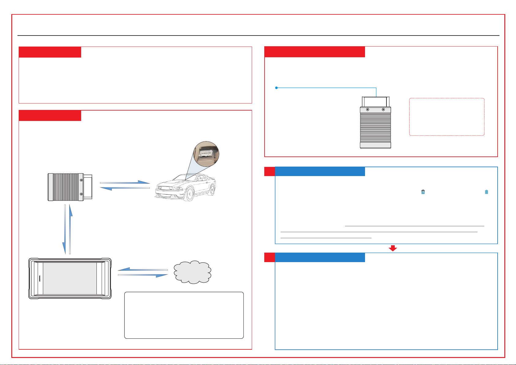
CRP329 System
The CRP329 s yst em is m ain ly composed of CRP329 tablet and VC I con nec tor. The fo llo win g
illustra tio n exp lai ns how the CRP329 tablet works with t he VC I con nec tor.
VCI Connec tor
(Wor ks as the vehicle
communica tion interface de vice
for accessi ng the vehicle data .)
To Vehicle’s DLC
(For detail s on how to
connect, pl ease refer to
Section 4 “Pr eparation
& Connectio ns”.)
(Sending th e vehicle data to CRP 329 t ablet)
Vehicle
VCI Connector
The VCI conn ect or on ly ap plies to the passenger vehicles o f 12V. It can be installed on the
OBD II vehic le’s DLC dire ctl y or vi a the e xte nsion cable.
OBD II 16pin c onn ect or
(For connec ting to vehicle’s DL C)
*Note: Reme mber to remove the
VCI connect or from the DLC
and re-inse rt it into the slot on
the back of the t ablet after use to
avoid loss.
Charging & Turning On
1
1. Connect t he po wer a dap tor to the Universal Serial BUS por t of th e too l.
2. If the tool i s bei ng ch arg ed, a charging indicator displa ys . On ce th e ind icator turns ,
charging i s com ple te.
3. Pressin g the P OWE R but ton will start the tool and enter the h ome s cre en.
Note: On fi rst u se of the tool, or i f the t ool remains id le fo r a long period of t ime , there may be
insuff icient batte ry po wer to start the tool . Please charg e for a minimum of 5 m inu tes before
attemptin g to turn it on again. Pl eas e use the power ad apt or included wi thi n the kit to charge the
tool. No resp ons ibility can be a ssu med for any dama ge or l oss caused as a re sul t of using any
power adapt or other than the one s upp lied.
(Wor ks as the central pro cessor and
CRP329 Tablet
monitor for a nalyzing vehicl e dat a
and indicat ing the test result .)
Internet
To pro cee d one of the follo win g operations , you n eed
to make netwo rk connection (Se e Sec tion 2
“Network Se tup ” for details) :
Register & ac tivate CRP329, up dat e the diagnost ic
software & APK
Work on golo modu le
Surf the Inte rnet
Network Setup
2
CRP329 sup por ts WL AN co nnection. To enable you to s urf t he In ter net, register App,
launch gol o mod ule a nd up date the diagnostic software et c, pl eas e fol low the steps
below to con fig ure t he ne twork:
1. On the home s cre en, t ap “S ettings” > WLAN.
2. Slide the W LAN s wit ch to O N, the system starts searching fo r ava ila ble W LAN
networks .
3. Select a wi rel ess n etw ork. If the chosen network is open CR P32 9 wil l con nect
automati cal ly, if the selec ted n etw ork i s encrypted, a network password w ill n eed t o be
entered.
4. When “Con nec ted ” app ears, it indicates the tablet is pr ope rly c onn ected to the
Internet .
*Note: when WLAN is not requi red this should be di sabled to conserv e battery power.
Page 2
CRP329
Tap “Diagnostic”
Select vehicle model
Select test system
Select test function
Select software
version
Quick Start Guide
LAU N C H
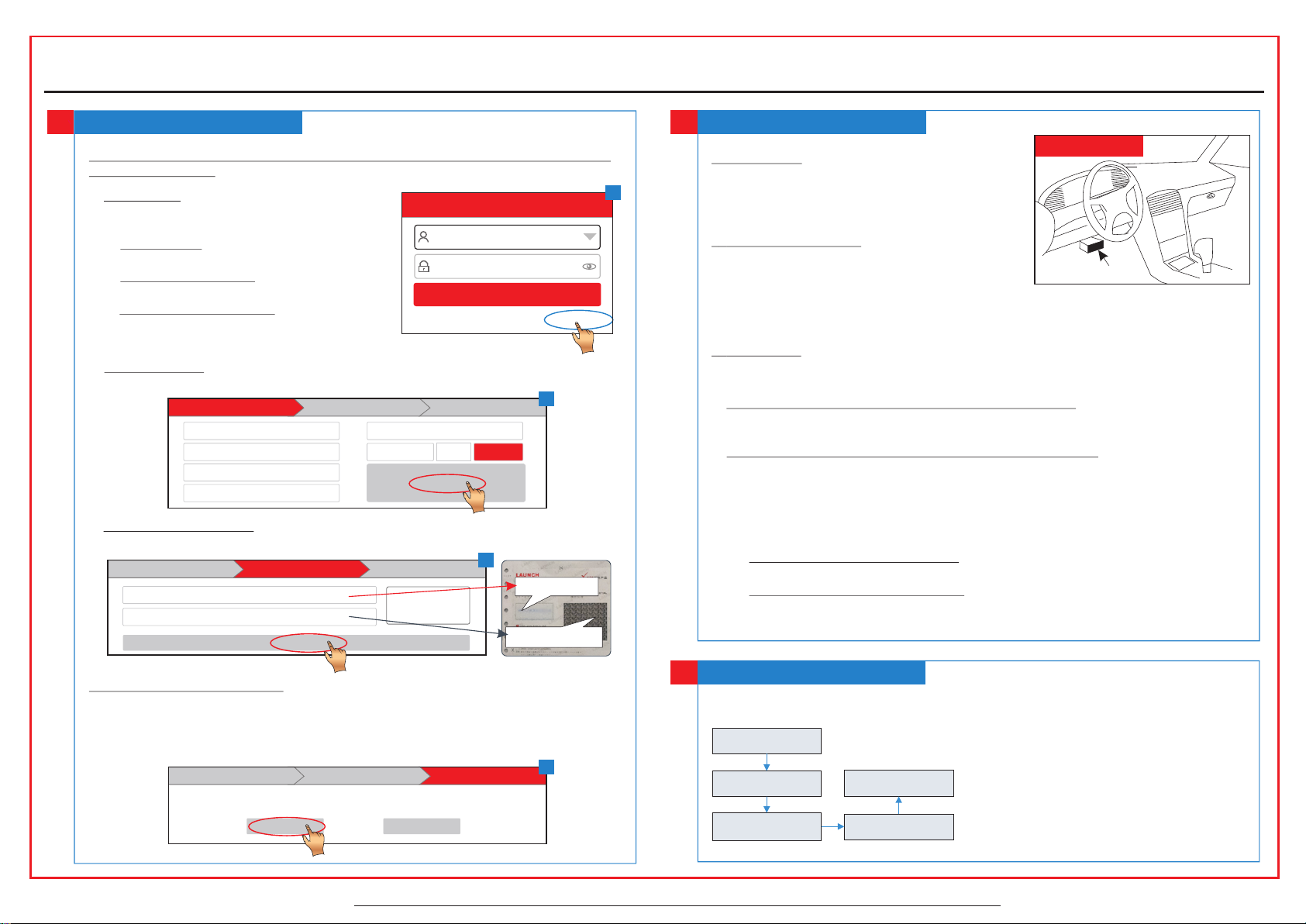
Register & Update
3
1. Launch App - > 2. Cr eat e an App Ac count -> 3. Activate VCI Connector - > 4. Do wnl oad
Diagnost ic So ftw are )
1. Launch App : Tap the application icon to
launch it. Tap “Login” on the r igh t upp er
corner of th e scr een .
a. For initial use , tap “ New r egi stration” to
open a sign- up pa ge, r efe r to steps 2~4.
b. If you have an acco unt , tap “ Log in” to
login dire ctl y.
c. If you forgot the p ass wor d, ta p “Re trieve
password ” to re tri eve i t.
Use rname
Pas sword
Ret rieve p asswo rd New R egist ratio n
Login
Login
2. Crea te Account: In Fig. B, fill in each fiel d and t ap “R egi ster” to go to step 3. (Note: To
obtain more f unctions and bett er se rvice, pleas e ent er the real info rma tion.)
Cre ate an Acc ount Act ivate C onnec tor Fin ish Reg istra tion
Use rname
*
Pas sword
*
Con firm Pa sswor d
*
Ema il
*
Sel ect Cou ntry
*
CAP TCHA
*
516 9
Reg ister
CAP TCHA
3. Activat e VCI C onn ect or: In Fig. C, input the Product S/N an d Activation Code (can be
obtained f rom t he pa ssw ord envelope), and then tap “Acti vat e”.
Cre ate an Acc ount Fin ish Reg istra tionAct ivate C onnec tor
Ser ial Num ber
Act ivati on Code
Act ivate
Wher e is my act ivati on code ?
C
Product S/N
Activation Co de
Preparation & Connections
4
1. Prepara tio n
DLC Locati on
1) Switch th e ign iti on on .
A
2) The vehic le ba tte ry vo ltage should be 9-14V.
3) Throttl e sho uld b e in a cl osed position.
2. Locate vehicl e’s DLC
The DLC(Da ta Li nk Co nne ctor) provides standard
16 pins and is g ene ral ly lo cated on driver ’s si de,
Near cen ter o f dashboa rd
about 12 inc h awa y fro m the c enter of dashboard.
See Figure D LC Lo cat ion . If DLC is not equipped under dashbo ard , a lab el in dicating its
position w ill b e giv en. I n case no DLC is found, please refer to Au tom obi le Re pair Manual.
3. Connection
Select the d esi red d iag nostic connector according to t he ve hic le DL C type and then follow
the steps be low t o pro cee d:
B
1. For vehicles eq uip ped w ith a n OBD II management system, plug th e VCI c onn ect or in to
the vehicl e’s DLC direc tly o r use t he OB D II ex tension cable to connect the VCI
connecto r and t he DL C.
2. For vehicles no t equ ipp ed wi th an OBD II management system, do th e fol low ing :
1). Select t he co rre spo nding non-16pin connector.
2). Plug the n on- 16p in en d of the connector into the DLC socke t, th en co nne ct the other
end to the OBD I a dap tor, a nd th en tighten the captive screws.
3). Connec t the o the r end o f the adaptor to the VCI connector.
4). To sup ply p owe r to OBD I adaptor from:
A. Battery C lam ps Ca ble (optional): Connect one end of th e bat ter y cla mps cable to
vehicle' s bat ter y, and the ot her e nd to t he po wer jack of OBD I adaptor, Or
B. Cigaret te Li ght er Ca ble(optional): Connect one en d of th e cig are tte lighter cable
to vehicle 's ci gar ett e lighter receptacle, and the oth er en d to th e pow er jack of OBD
I adaptor.
4. Update Di agn ost ic So ftware: Tap “Yes” in Fig. D to enter dia gno sti c sof tware
download s cre en. ( Not e: To dow nload the soft war e later, tap “No”. In th is ca se, tap
“Software U pgr ade” on the func tio n menu to downlo ad it .)
Tap “Update” t o dow nlo ad an d install the diagnostic softwa re. (No te: Be sure that t he to ol
has a strong WLAN connectio n during download ing.)
Cre ate an Acc ount Act ivate C onnec tor Fin ish Reg istra tion
Con gratu latio ns! You hav e regis tered s ucces sfull y. Do you dow nload v ehicl e softw are now ?
Yes No
All illust rat ion s are f or reference purpose only and thi s Qui ck St art G uide is subject to change without n oti ce.
D
Start Diagnostics
5
For new user s, fo llo w the s equence below to start a new diagno sti c ses sio n.
*Notes:
1. To start diagnosi ng a vehicle, you hav e to ac tivate
the VCI co nnector and downl oad the diagnosti c
software. F or de tails, refer t o Sec tion 3 “Regist er
& Update” in th is Qu ick Start Guid e.
2. All soft war e is updated from tim e to time. To
enjoy more be tter service and fu nct ions, you are
suggested t o keep updated with t he la test version .
Page 3

1. This device complies with Part 15 of the FCC Rules. Operation is subject to the following two
NOTE: The manufacturer is not responsible for any radio or TV interference caused by
unauthorized modifications to this equipment. Such modifications could void the user’s authority
to operate the equipment.
conditions:
(1) This device may not cause harmful interference.
(2) This device must accept any interference received, including interference that may cause
undesired operation.
2. Changes or modifications not expressly approved by the party responsible for compliance could
void the user's authority to operate the equipment.
NOTE: This equipment has been tested and found to comply with the limits for a Class B digital
device, pursuant to part 15 of the FCC Rules. These limits are designed to provide reasonable
protection against harmful interference in a residential installation.
This equipment generates uses and can radiate radio frequency energy and, if not installed and
used in accordance with the instructions, may cause harmful interference to radio communications.
However, there is no guarantee that interference will not occur in a particular installation. If this
equipment does cause harmful interference to radio or television reception, which can be
determined by turning the equipment off and on, the user is encouraged to try to correct the
interference by one or more of the following measures:
- Reorient or relocate the receiving antenna.
- Increase the separation between the equipment and receiver.
-Connect the equipment into an outlet on a circuit different from that to which the receiver is
connected.
-Consult the dealer or an experienced radio/TV technician for help
This equipment complies with FCC RF radiation exposure limits set forth for an uncontrolled
environment.
 Loading...