

Page 1

Automotive Diagnosis Terminal
Launch Tech Co., Ltd.
(DBSCar III)
Model No.: DS301
User Manual
(V1.0)
Page 2
1. Automotive Diagnosis Terminal (DBSCar III)
Launch Tech Co., Ltd.
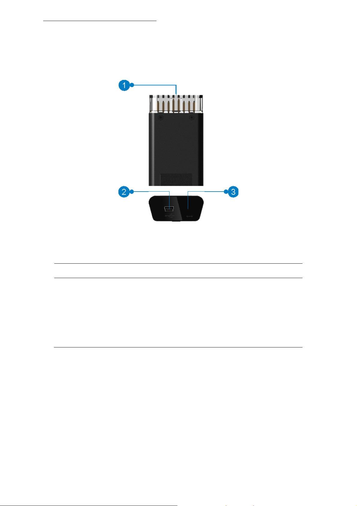
Fig. 1-1 Diagnostic connector (Onl
①
OBD-16 diagnostic connector
②
Mini USB port
③
Mode indicator
2. Technical Parameters
¾ Working voltage: DC 9 -18V
¾ Average working current: About 85mA
¾ Standby current: About 55mA
y applies for 12V cars)
To connect on vehicle’s OBD2 DLC.
For connecting the USB cable to the diagnostic tool.
It has three different modes:
y It illuminates red when the connector is plugged into
the vehicle’s DLC.
y It illumin ates blue if the connector is communicating
with the vehicle via Bluetooth.
y It illuminates green when the connector is connected
to the diagnostic tool via USB cable.
¾ Working temperature: -10 to 50℃
¾ Storage temperature: -30 to 70℃
¾ Storage humidity: <80%
¾ Working humidity: <60%
Page 3

3. Connections
Launch Tech Co., Ltd.
3.1 Preparation
y Turn on the vehicle power supply.
y Throttle should be closed at its close position.
3.2 DLC location
The DLC (Data Link Connector or Diagnostic Link Connector) is typically a standard 16 pin connector
where diagnostic code readers interface with the vehicle’s on-board computer. The DLC is usually
located 12 inches from the center of the instrument panel (dash), under or around t he driver’s side for
most vehicles. If Data Link Connector is not located under dashboard, a label should be there telling
location. For some Asian and European vehicles, the DLC is located behind the ashtray and the ashtray
must be removed to access the connector. If the DLC cannot be found, refer to the vehicle’s service
manual for the location.
Fig. 3-1
3.3 Vehicle connection
The method used to connect the diagnostic connector to a vehicle’s DLC depends on the vehicle’s
configuration as follows:
y A vehicle equipped with an OBD II management system supplies both communication and 12V power
through a standardized DLC.
y A vehicle not equipped with an OBD II management system supplies communication through a DLC
connection, and in some cases supplies 12V power through the cigarette lighter receptacle or a
connection to the vehicle battery.
Follow the steps mentioned below to connect OBD II vehicle
1. Locate vehicle’s DLC socket.
2. Plug the diagnostic connector into the vehicle’s DLC socket (It is suggested to use the OBD II
extension cable to connect the diagnostic connector and DLC socket.).
:
Page 4

Fig. 3-2
Launch Tech Co., Ltd.
For non-OBDII vehicle, proceed as follows:
1. Locate vehicle’s DLC socket.
2. Select the corresponding non-16pin connector.
3. Plug the non-16pin end of the connector into the DLC socket, then connect the other end to the OBD I
adaptor, and then tighten the captive screws.
4. Connect the other end of the adaptor to the included diagnostic connector.
5. To supply power to OBD I adaptor from:
A. Cigarette Lighter
receptacle, and the other end to the power jack of OBD I adaptor.
B. Battery Clamps Cable:
other end to the power jack of OBD I adaptor.
: Connect one end of the cigarette lighter cable to vehicle’s cigarette lighter
Fig. 3-3
Connect one end of the battery clamps cable to vehicle’s battery, and the
Automotive Diagnosis Terminal (Model DS301) is in compliance with the essential Requirements and
other rele
Environment friendly disposal
vant provisions of Directive 1999/5/EC.
Fig. 3-4
Page 5

You can help protect the environment!
Launch Tech Co., Ltd.
Please remember to respect the local regulations:
hand in the non-working electrical equipments to
an appropriate waste disposal centre.
FCC Caution:
This device complies with part 15 of the FCC Rules. Operation is subject to the following two
conditions: (1) This device may not cause harmful interference, and (2) this device must accept a ny
interference received, including interference that may cause undesired operation.
Any Changes or modifications not expressly approved by the p arty responsible for compliance could
void the user's authority to operate the equipment.
This equipment has been tested and found to comply with the limits for a Class B digital device,
pursuant to part 15 of the FCC Rules. These limits are designed to pr ovide reasonable protection
against harmful interference in a residential installation. This equipment generates uses and can
radiate radio frequency energy and, if not installed and used in accordance with the instructions, ma y
cause harmful interference to radio communications. However, there is no guarantee that interference
will not occur in a particular installation. If this equipment does cause harmful interfer ence to radio or
television reception, which can be determined by turning the equipment off and on, the user is
encouraged to try to correct the interference by one or more of the following measures:
-Reorient or relocate the receiving antenna.
-Increase the separation between the equipment and receiver.
-Connect the equipment into an outlet on a circuit different from that to which the receiver is
connected.
-Consult the dealer or an experienced radio/TV technician for help.
The device has been evaluated to meet general RF exposure requirement.
To maintain compliance with FCC’s RF exposure guidelines, this equipment should be installed and
operated with a minimum distance of 20cm between the radiator and your body.
 Loading...