

Page 1

LAUNCH X431 PAD Scopebox User’s Manual
Precaution on Operation
z The appliance is a sophisticated electronic device, never have it clashed
when in use.
z Main unit screen may flash at the moment of engine ignition, which is
normal.
z You may unplug the main unit if the program can not be actuated or
confused screen occurs. Plug again to continue the operation.
z Make sure the appliance is properly connected to the DLC to avoid
communication interruptions.
z During operation, keep the screen upward and leveled.
z Be careful when plugging and unplugging the main cable and diagnostic
connector. Tighten the screw before operation to avoid unexpected
disconnecting and/or damage to the port.
z Handle with care. Avoid collision. Unplug the power after operation.
z After the operation, the stylus shall be inserted into the slot on the main
unit, and put away the cable and connector, etc accessories to the box to
avoid the lost.
z Unplug the power cable by holding the connector, not the cable itself.
Page 2

LAUNCH X431 PAD Scopebox User’s Manual
Table of Contents
1 FOREWORD......................................................................................1
1.1
INTRODUCTIONS ...........................................................................1
1.2
PRODUCT FEATURES.....................................................................1
1.3
PRODUCT FUNCTION.....................................................................2
1.4
TECHNICAL PARAMETERS ..............................................................2
2 STRUCTURE AND ACCESSORIES ................................................. 3
2.1
SCOPEBOX STRUCTURE................................................................3
2.2
SCOPEBOX ACCESSORIES............................................................. 4
3 AUTOMOTIVE OSCILLOSCOPE......................................................6
3.1
CONNECTION................................................................................ 6
3.2
INITIAL INTERFACE INTRODUCTION.................................................6
3.3
OPERATIONS.................................................................................7
3.3.1 Channel selection and attributes
setting
..............................7
3.3.2 Trigger setting.......................................................................9
3.3.3 A
uto cal
i
bration...................................................................11
3.3.4 Display settings ................................................................. 12
3.3.5 Channel and cursor meas
ur
ement.................................... 12
3.3.6 File management...............................................................
13
3.3.7 View the softw
a
re version ................................................. 15
3.3.8 Exit the application............................................................
15
4 AUT OMOTIVE IGNITION WAVEFORM .......................................... 16
4.1
SECONDARY-DISTRIBUTOR IGNITION ANALYSIS............................. 16
4.2
SECONDARY-SIMULTANEOUS IGNITION ANALYSIS.......................... 19
4.3
SECONDARY-DIRECT IGNITION ANALYSIS...................................... 20
4.4
WA VEFORM ANAL YSIS MODE........................................................ 22
Page 3

LAUNCH X431 PAD Scopebox User’s Manual
1
1 Foreword
1.1 Introductions
X-431 PAD is a new generation of sophisticated and integrated automotive
diagnostic product with colorful screen and powerful functions developed by
LAUNCH, and Scopebox is an optional function box for X-431 PAD , including
automotive oscilloscope and automotive ignition waveform.
Automotive oscilloscope can make the auto repair technician quickly judged
the fault
s on automotive electronic equi
pment and wiring, and the oscilloscope
sweep speed is far greater than the signal frequency of such vehicles, usually
5-10 times of the measured signal. The automotive oscilloscope not only can
quickly capture the circuit signal, but also can slowly display the waveform to
observe and analyze. It can also record and store the tested signal waveform
which can be played back to observe for the fast signal, having great
convenience to failure analysis. Either high-speed signal (e.g.: injection nozzle,
intermittent fault signal) or the slow-speed signal (e.g. the throttle position
change and the oxygen sensor signal) can be observed through automotive
oscilloscope in an appropriate waveform.
The electronic signal can be compared and judged via measuring five
parameters index
es. The five parameters indexes are the amplitude (the
maximum voltage of signal), the frequency (the cy cle time of signal), the shape
(the appearance of signal), the pulse width (the duty cycle or the time range of
signal), and the array (the repetition characteristic of signal), which can be
tested, displayed, saved by the automotive oscilloscope. Via the waveform
analysis can further detect the circuit fault on sensors, actuators, circuits, and
electronic control units, etc.
1.2 Product features
z Rapidly capture the circuit signal.
z Display waveform slowly for observation and analysis.
z Record and store the tested signal waveform for playback and failure
analy
sis.
Page 4

LAUNCH X431 PAD Scopebox User’s Manual
2
z Detect, display and store all the electrical signal of five parameters,
namely amplitude, frequenc
y, shape, pulse width, and array.
1.3 Product function
Provides specialized automotive oscilloscope function and supports ignition
waveform analysis.
1.4 Technical parameters
Scopebox: 4 channels, highest sampling frequency 200MHZ, max storage
depth 64MSa, 8-bit resolution.
Page 5
LAUNCH X431 PAD Scopebox User’s Manual
2 Structure and Accessories
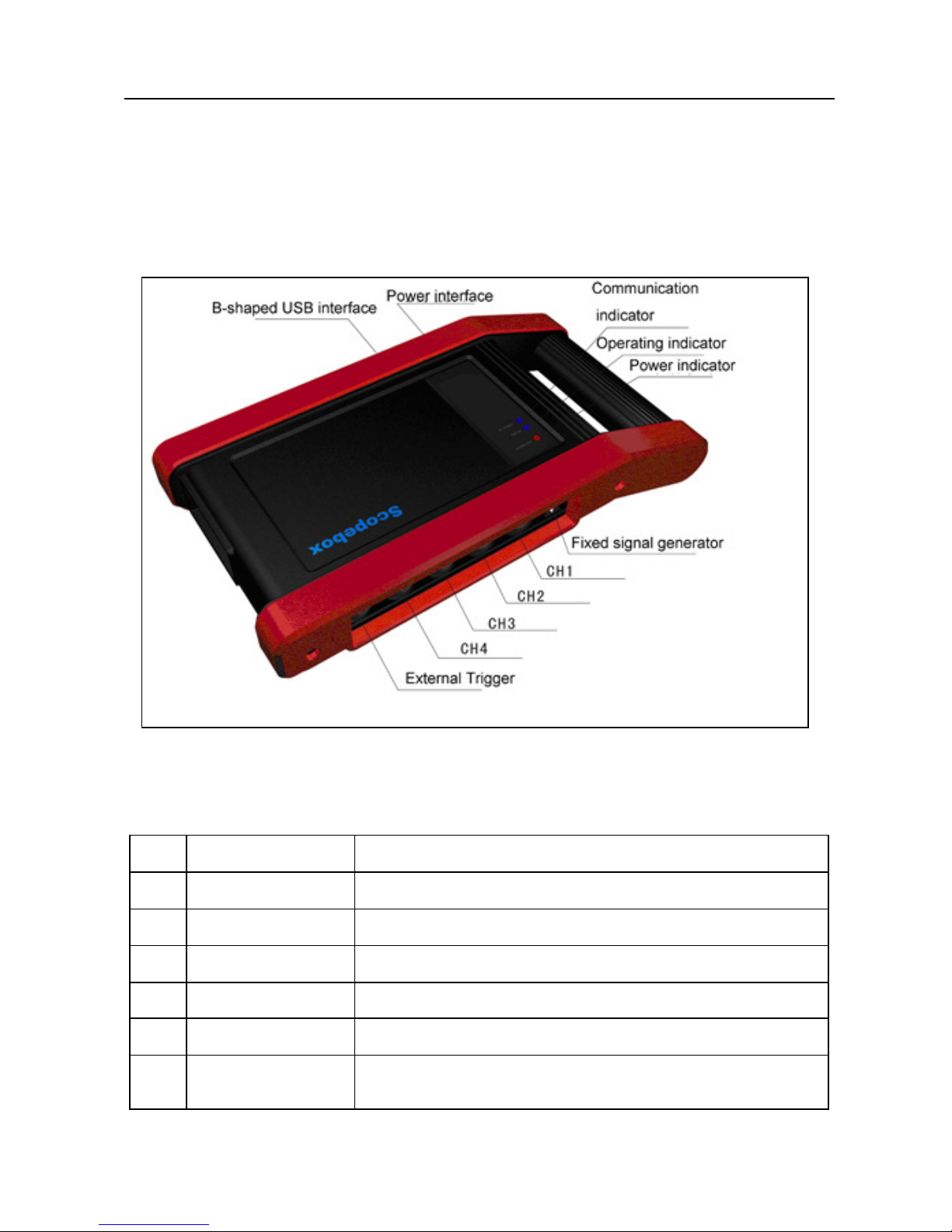
2.1 Scopebox structure
Fig 2-1 Scopebox Structure Diagram
Table 2-1 shows the ports and indicators for X-431 PAD Scopebox
No. Name Description
1 CH1 Channel 1
2 CH2 Channel 2
3 CH3 Channel 3
4 CH4 Channel 4
5 External trigger External trigger signal
6 Fixed signal
generator
Generate a square signal with fixed 1K frequency
3
Page 6
LAUNCH X431 PAD Scopebox User’s Manual
7 Power indicator Oscilloscope power indicator, which will be steady
red after the oscilloscope is powered on
8 Operating
indicator
The indicator will be steady green after the
oscilloscope operated.
9 Communication
indicator
After the data communication, the indicator will
blink (Green).
10 Power interface Connect to power supply via the power adapter.
11 B-shaped USB
interface
Connect main unit via USB connect line as
separated individual USB devices
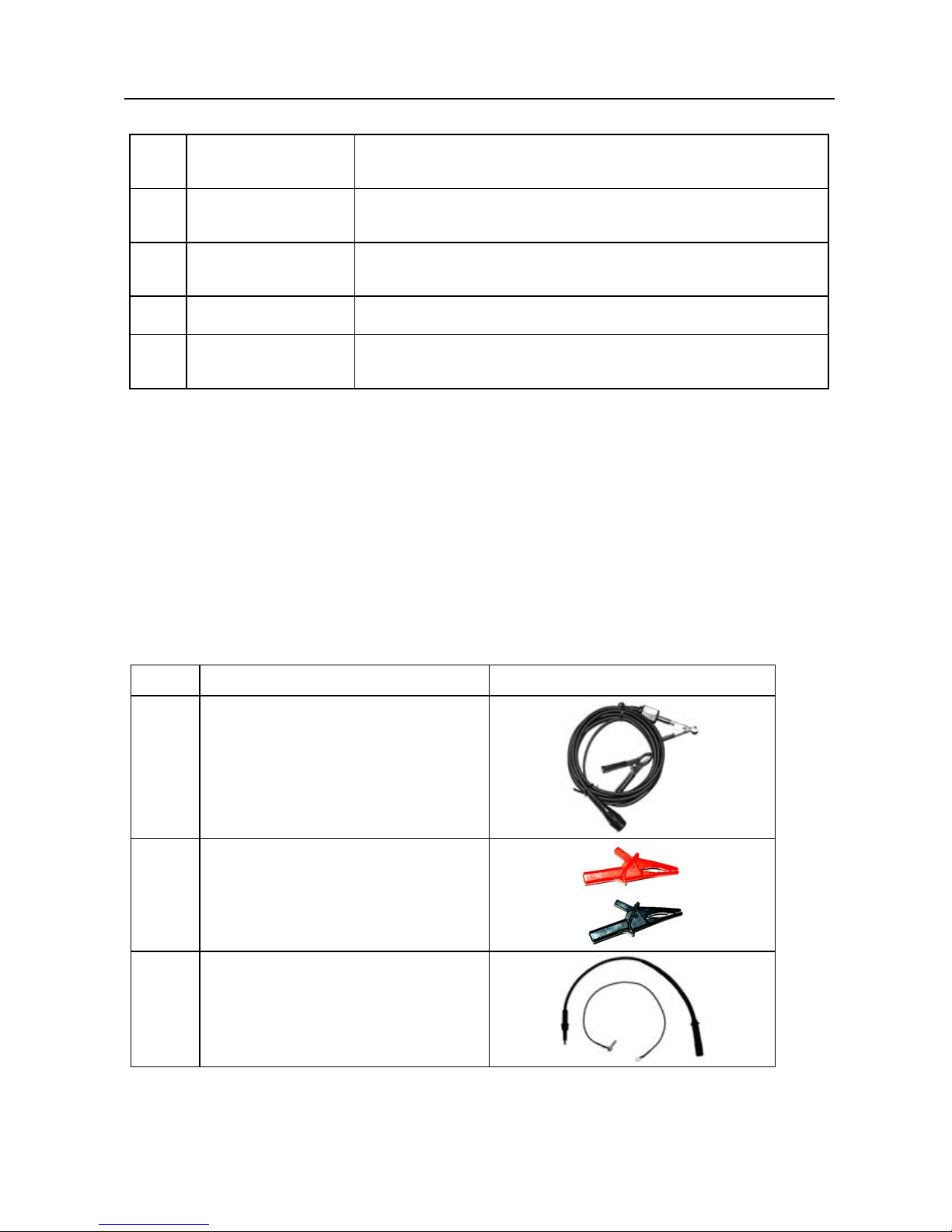
2.2 Scopebox accessories
Scopebox includes the secondary pickup cable for 4-channel oscilloscope,
crocodile clips for 4-channel oscilloscope, etc. See Table 2-2.
As the product configuration can be different, the accessories inc
luded with the
product may differ from the accessories listed on this manual. Please see the
packing list attached to the product for the detailed accessor ies.
Table 2-2 Accessory checklist
No. Name Picture
1 Secondary ignition pickup for
4-channel oscilloscope
2 Crocodile clips for 4-channel
Oscilloscope
3 Direct ignition extension cord
4
Page 7
LAUNCH X431 PAD Scopebox User’s Manual
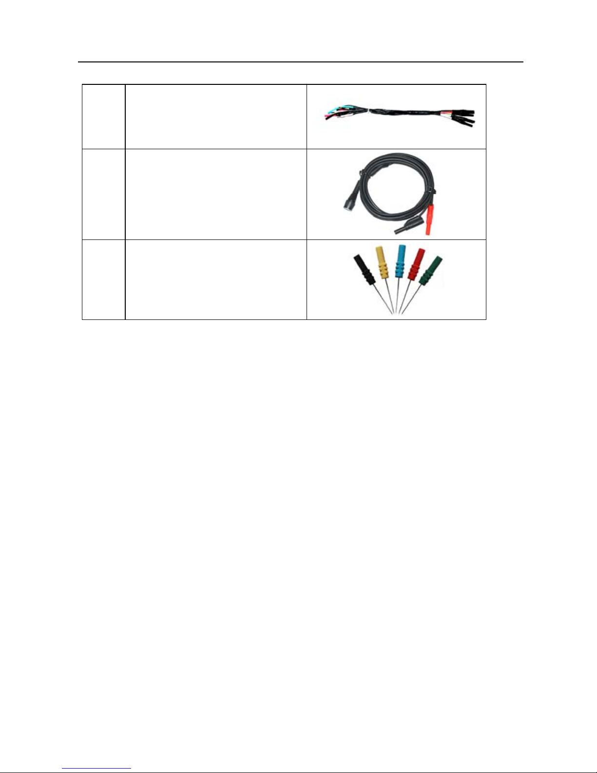
4 6-way universal guide line for
4-channel oscilloscope
5 BNC to 4mm connector test
cable
6 Pin connector for 4-channel
oscilloscope
5
Page 8

LAUNCH X431 PAD Scopebox User’s Manual
6
3 Automotive Oscilloscope
3.1 Connection
X-431 PAD Scopebox should work with the X431 PAD main unit.
1. Firstly, power on the main unit (Connect one end of the power adaptor into
the power interface of main unit, and
the other end to the DC 12V power
supply. Alternatively it can be also powered by cigarette lighter cable and
double clip power cord).
2. Then plug one end of ground cable of oscilloscope into ex
ternal trigger
channel (GND), the other end should be grounded.
3. Connect one end of probe cable of oscilloscope
to the CH1, CH2, CH3, or
CH4 on oscilloscope module, and then connect the other end to related
signal terminal.
Warning: please use the specific capacitance probe when diagnosing the
ignit
ion high voltage line. Never connect the oscilloscope to the ignition
secondary circuit directly.
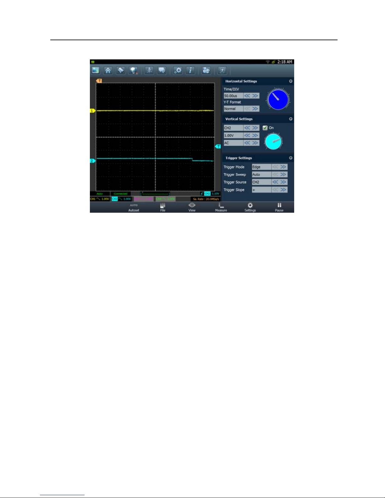
3.2 Initial interface introduction
Fig. 3-1 displays the initial interface of oscilloscope.
Page 9
LAUNCH X431 PAD Scopebox User’s Manual
Fig.3-1
Button descriptions:
[Autoset]: It indicates a
u
to trigger setting. Based on the characteristics of
measured signal, the oscilloscope will automatically set the horizontal bas eline,
vertical sensitivity and trigger condition so that the waveform can be display ed.
[File]: provide
s
waveform record and waveform replay.
[View]:
Calibration and display settings are available.
[Measure]
: includes signa
l source measurement, cursor measurement and
clear measurement.
[Settings]: display
s or hides the parameter settings area including horizontal
settings, vertical settings and trigger settings.
[Start/stop]: start
s/stops collecting oscilloscope waveforms.
3.3 Operations
3.3.1 Channel selection and attributes setting
<1> Channel selection
There are two ways available for channel selection: (See Fig. 3-2)
A. Select from the channel column shown at the bottom of the waveform
7
Page 10
LAUNCH X431 PAD Scopebox User’s Manual
display area;
B. Select from Vertical settings.
Note: For better comparison and identification, each channel and waveform
are marked in dif
f
erent colors.
Fig.3-2
<2> Channel attributes setting
Channel attributes can be set via horizonta
l settings and vertical settings.
Horizontal Settings
User can make some settings directly by clicking << or >> next to options.
Alternatively
, Click
located in the upper right corner of the horizontal
settings to make more settings. See Fig. 3-3.
Fig. 3-3
8
Page 11
LAUNCH X431 PAD Scopebox User’s Manual
Options descriptions:
Time/DIV: click << or >> to adjust;
Y-T Format: click << or >> to adjust. It includes 3 options: Normal, Scan and
Scroll (from ri
ght to left).
V ertical Setting s
User can make some settings directly by clicking << or >> next to options.
Alternatively
, Click
located in the upper right corner of the vertical settings
to make more settings. See Fig. 3-4.
Fig. 3-4
Options descriptions:
A. Channel selection;
B. Channel switch selection;
C. Channel voltage adjustment;
D. Channel coupling modes sele
ction: DC,
AC or Ground;
E. Channel probe selection;
F. Bandwidth limit switch;
G. Channel reverse phase switch.
3.3.2 Trigger setting
Trigger indicates that when certain waveform meets the conditions that are
predefined according to the requirements, the oscilloscope captures the
waveform and its adjacent section, and then presents it on the screen.
<1> T r igger mo de
It is classified into 3 categories: Pulse Width and Edge.
[Edge]: It is the most common and ef
fective trigger mode, which is widely used
9
Page 12
LAUNCH X431 PAD Scopebox User’s Manual
in most applications. Edge trigger only detects the edges, polarities, and
voltage of signal. When the voltage of measured signal varies as identical as
the preset one (rising edge or falling edge), and the value becomes same as
trigger voltage, the oscilloscope will be triggered and capture the waveform.
[Pulse Width]: T
rigger happens when it reaches to the pulse width.
Fig. 3-5 and Fig. 3-6 show edge trigger, pulse widt
h trigger setting interfaces.
Fig. 3-5
Fig. 3-6
<2> Trigger Sweep
Auto, Normal and Single are included.
Auto: It indicates that no matter w
hether it meets the trigger conditions, it will
refresh the waveform in real time. In this case, the waveform displ ayed on the
screen seems swaying;
Normal: Only
it meet
s the trigger conditions can trigger be activated.
Otherwise the waveform will keep still.
Single: In this mode, it only
captures the waveform that generates for the first
time the trigger conditions are met, and then stops after finishing capture.
10
Page 13
LAUNCH X431 PAD Scopebox User’s Manual
<3> Trigger source
Trigger source means w hich channel signa l w ill be measured as trigger object.
Before making settings to trigger mode and v
oltage of certain channel, you
have to choose the target channel.
3.3.3 Auto calibration
This option enables you to obtain a precise measurement of measured signal.
Auto calibration mainly includes: calibration of analog channel, trigger voltage
calibration of trigger circuit and nonlinear calibration of horizontal baseline
movement.
Click “View” and then click [Calibration], a dialog box simil
ar to Fig. 3-8 will
appear.
Fig. 3-8
Check the box before the channel to select it. T
o select all, click [Check All]. To
deselect it, just click [Reverse]. After choosing the desired channel(s), click
[Start] to start calibration and [Calibration] button will be temporarily invalid
during calibrating. Click [Stop] to stop calibrating. Once it becomes active, it
indicates calibration has completed.
Notes: In process of calibration, make sure CH1/CH2/CH3/CH4 has no signal
11
Page 14
LAUNCH X431 PAD Scopebox User’s Manual
input. Moreover, calibration may take several minutes and please be patient to
wait.
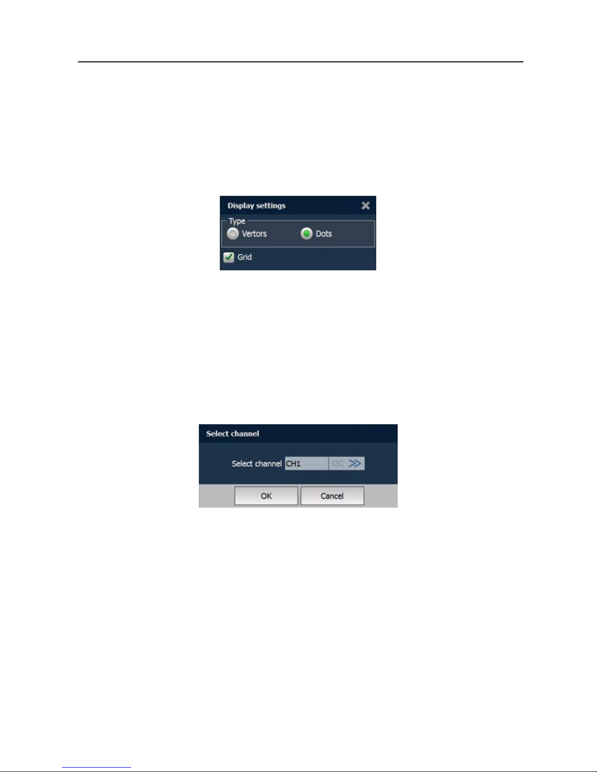
3.3.4 Display settings
Click “View” and then [Display settings] to enter the setting screen. See Fig.
3-9.
Fig. 3-9
Click “Vectors” or “Dots” to define display
mode. Check/uncheck the box
before Grid to open/close grid display.
3.3.5 Channel and cursor measurement
<1> Channel measurement
Click “Measure” and then [Source], a screen similar to Fig. 3-10 will appear.
Fig. 3-10
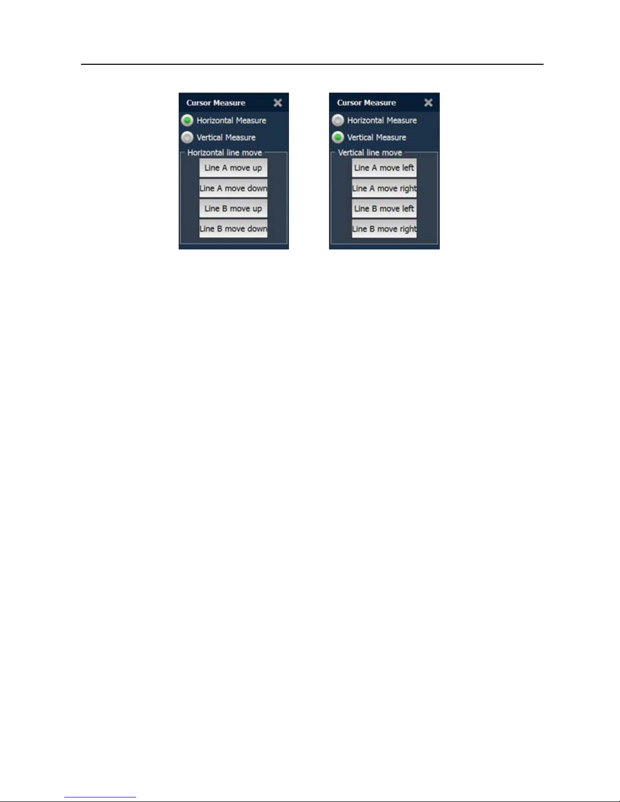
<2> Cursor measurement
Click “Measure” and then [Cursor Measure], a screen similar to Fig. 3-11 will
appear.
Not
e: if no desired channel is selected, the system will take the current source
as the default channel.
12
Page 15
LAUNCH X431 PAD Scopebox User’s Manual
Fig. 3-11 Fig. 3-12
Horizontal Measure is for voltage (see Fig. 3-11) and vertical measure is for
timebase (see Fi
g. 3-12).
Options descriptions:
[A Line / B Line move up / do wn]: fine adjustment for volt
age. A line is a solid
line and B line is a dotted line;
[A Line / B Line move left / right]: fine adju
stment for timebase. A line is a
solid line and B line is a dotted line.
<3> Clear Measurement
Click “Measure” and then [Clear Measure], the s
ystem will clear the
measurement result.
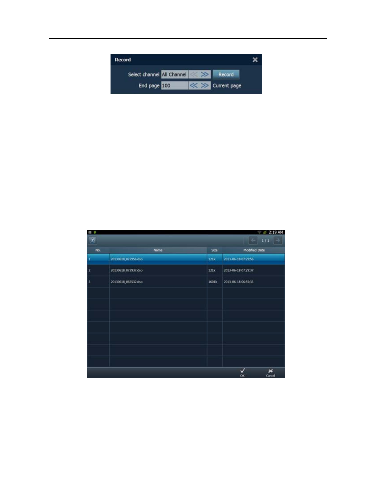
3.3.6 File management
<1> Record waveform
This function is used to record waveforms that are collected by oscilloscope at
a period, and save it as dat
a file which can be played back in future.
It can be performed only when the oscilloscope is collecting data in Normal
mode.
Click [File], then select [Record] from the pop-up menu to start recording.
See
Fig. 3-13.
13
Page 16
LAUNCH X431 PAD Scopebox User’s Manual
Fig.3-13
Click [Record] to start recording, and the Record button becomes S
top button.
Click [Stop] to stop recording. While recording, the recorded pages will be
shown on the screen.
<2> Import waveform for playback
The Import function enables you to import the stored waveform file for
playback and review
. During replaying, the oscilloscope stops collecting data
automatically.
Click [File], then select [Waveform replay] from the pop-up menu to enter
a
screen similar to Fig. 3-14.
Fig.3-14
Select the playback file first, and then click [OK] button to open the
waveform
file, then use channel attributes setting to adjust the waveform display.
To delete the waveform file, please enter “My Data” and choose the
14
Page 17

LAUNCH X431 PAD Scopebox User’s Manual
corresponding folder to perform delete operation.
<3> Print waveform
This option allows you to print out the latest collected dat
a while the
oscilloscope stops collecting dat a. While printin g, the oscilloscope should be in
stop mode.
Click
on the shortcut bar to start printing.
3.3.7 View the software version
Click to view the version information of the oscilloscope.
3.3.8 Exit the application
Click to exit the current application.
15
Page 18

LAUNCH X431 PAD Scopebox User’s Manual
16
4 Automotive Ignition waveform
The ignition system is the system which has greatest impact on the
performances of gasoline engine, as the statistical data shows that nearly half
of the failures are caused by poor work of electrical system. And the
performance tests of engine often start from the ignition system. Nowadays
ignition system includes distributor and distributorless. Distributorless includes
independent ignition and simultaneous ig nition.
1. Distributor ignition system i.e. contact break
er with contact-controlled
ignition system (commonly known as the platinum) and contact breaker
with noncontact-controlled ignition system combined with magnet, hall
components or infrared.
2. Independent ignition system: crankshaft sensor send out the ignition
timing si
gnal and cylinder identification signal so that the ignition system
can send out ignition signal to specified cylinder in specified time, each
cylinder has its independent ignition coil.
3. Simultaneous ignition system: two cylinders share one ignition coil, when
two c
ylinder pistons reach top dead center at the same time (one is
compression, another is the exhaust), two spark plugs will be ignited at
the same time, at this time, the ignition for the former cylinder is in
high-pressure low temperature gas mixture, the ignition is valid, while for
the latter one is in low-pressure high temperature exhaust gas, the
ignition is invalid.
X-431 PAD can test and analyze the secondary signal for various engine
ignit
ion systems.
4.1 Secondary-distributor ignition analysis
Connections: Plug the BNC end of secondary ignition pickup into
CH1/CH2/CH3/CH4 channel of Scopebox, then connect the high-voltage clip
to high-voltage line, and crocodile clips to groun d.
Tips: Common ignition sequence (the specific sequence is subject to the
actual engine ig
nition sequence)
Page 19

LAUNCH X431 PAD Scopebox User’s Manual
17
Four-stroke in-line four-cylinder: 1—2—4—3, or 1—3—4—2
Four-stroke in-line six-cylinder: 1—5—3—6—2—4, or 1—4—2—6—3—5
Four-stroke in-line eight-cylinder: 1—8—4—3—6—5—7—2
Five-cylinder: 1-2-4-5-3
V 6 engine: generally speaking, based on the person sitting on the driver cab,
if the right side
cylinder numbers on the right side, from the front to the back
are as follows: 1, 3, 5; and the cylinder numbers on the left side, from the front
to the back are as follows: 2, 4, 6; then the ignition sequence is: 1-4-5-2-
3-6. If the cylinder numbers on the right side, from the front to the back are as
follows: 2, 4, 6; and cylinder numbers on the left side, from the front to the back
are as follows:1, 3, 5; then the ignition sequence is: 1-6-5-4-3-2.
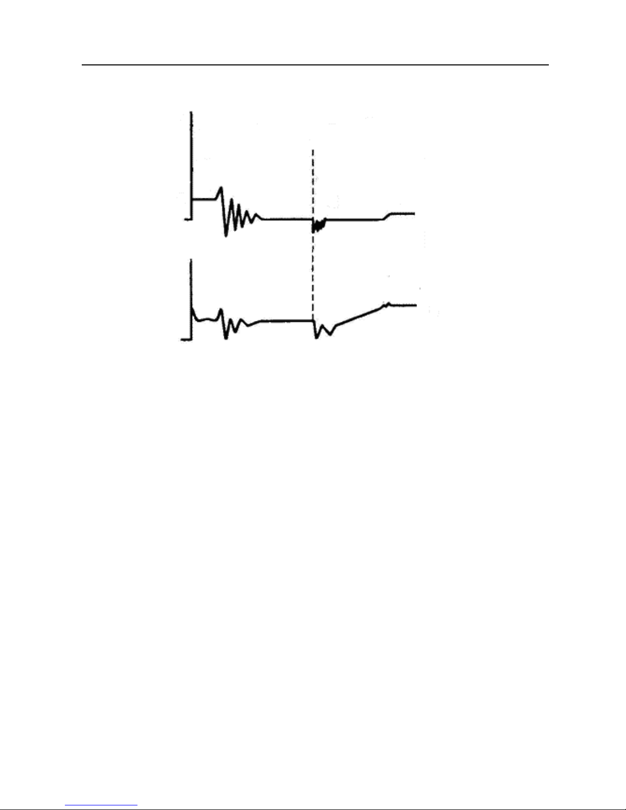
The Figure 4-1 below shows the normal ignition w aveform of distributor ignition
s
y
stem, the upper one is the secondary waveform, and the lower one is the
primary waveform.
The secondary waveform
A section is cont act open per iod; B section is make cont act perio d, which is the
magnetizing field of ignition coil.
Page 20

LAUNCH X431 PAD Scopebox User’s Manual
Fig. 4-1
1) Contact break point: the primary circuit of igniti
on coil cut off, the
secondary voltage was sensed and increased sharply
2) Ignition voltage: secondary coil volta
ge overcome the damper of high
voltage line, the contact breaker gap and the spark plug gap to release
magnetizing energy, 1-2 section is the breakdown voltage
3) Spark voltage: For the capacitor discharge voltage
4) Ignition voltage pulse: For the charge and discharge sections
5)
Spark line: The inductance discharge process, i.e. the mutual induct
ance
voltage of ignition coil maint ains the conduction of secondary circuit
6) Contact point close the current flow into
primary coil, the primary coil
oscillates due to the mutual inductance.
Primary ignition waveform
Section
a shows the voltage oscillation on the primary circuit due to the
magnetic induct
ion of spark in the duration;
Section b shows the damped oscillation genera
ted by remaining magnetic field
18
Page 21

LAUNCH X431 PAD Scopebox User’s Manual
energy after the spark;
Section c shows the make cont
act magneting period of primary coil.
Seen from the waveform, the amplitudes of breaker contact closed angle,
break angle and
breakdown voltage and spark voltage are very clear, besides,
the spark delay period and two oscillations can also be tested. For the ignition
system without faults, compared with the whole cycle, the cont act closed ang le
just 45%-50% (four-cylinder), 63%-70% (six-cylinder), or 64%-71%
(eight-cyliner); the breakdown voltage is over 15kv; the spark voltage is about
9kV, the spark period is greater than 0.8ms. If these values or waveform are
abnormal, it means there is fault or the system needs to be adjusted.
4.2 Secondary-simultaneous ignition analysis
Connections: Plug the BNC end of secondary ignition pickup into
CH1/CH2/CH3/CH4 channel of Scopebox, then connect the high-voltage clip
to high-voltage line, and crocodile clips to groun d.
Connection as shown in figure 4-2:
Fig. 4-2
19
Page 22
LAUNCH X431 PAD Scopebox User’s Manual
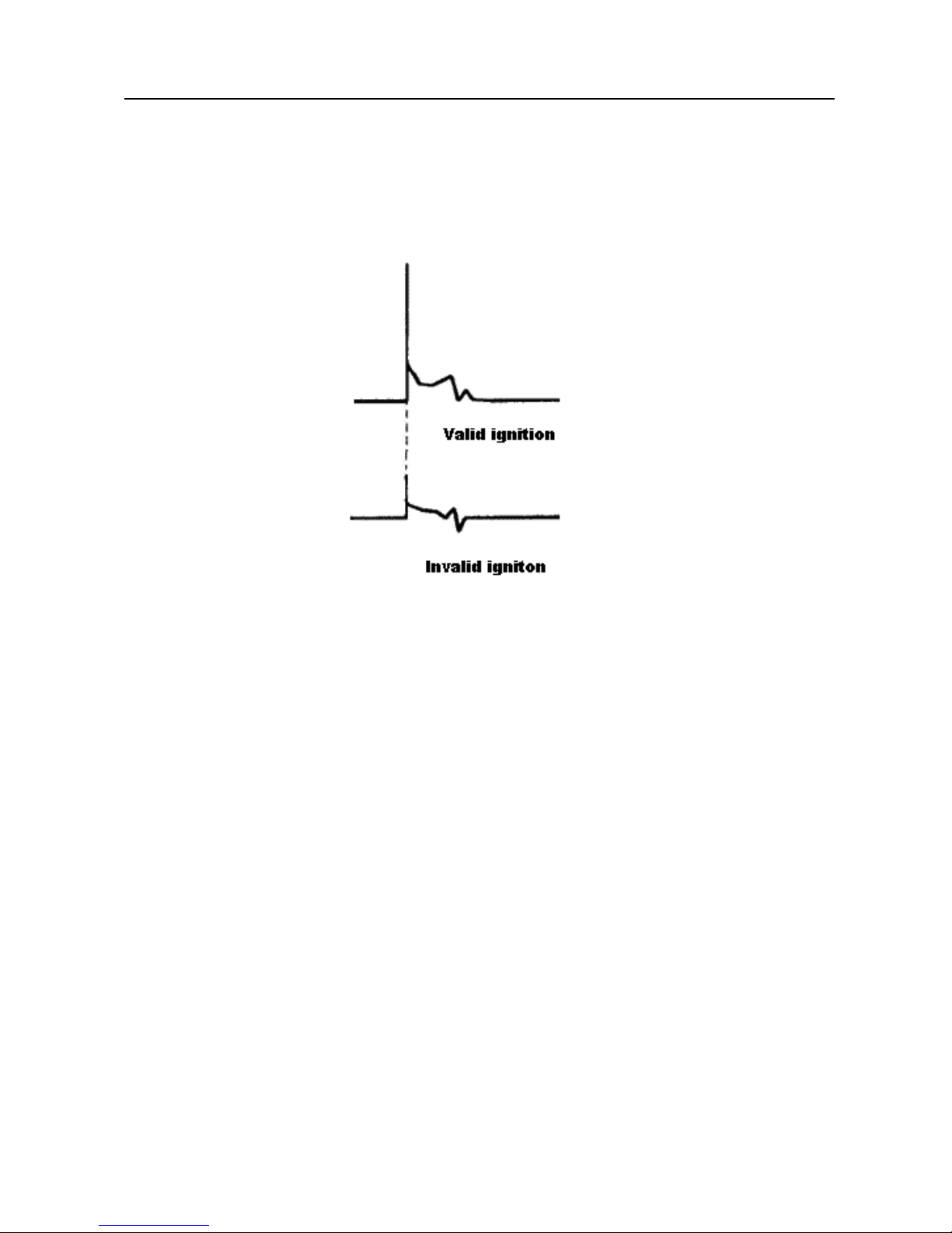
Fig. 4-3 below shows the valid and invalid ignition waveforms. Under the
working status of valid ignition, the breakdown voltage and spark voltage are
higher because the cylinder is filled with fresh combustible mixture gas, which
has a lower ionization level and vice versa.
Fig. 4-3
4.3 Secondary-direct ignition analysis
Connection:
1) When the high-voltage wire is exposed, plug the BNC end of secondary
ignit
ion pickup into CH1/CH2/CH3/CH4 channel of Scopebox, then
connect the high-voltage clip to high-voltage line, and crocodile clips to
ground.
2) If no high-voltage wire exposes, dismantle ignition coil of tested cylinder
and use direct
ignition extension cord. Connect one end to ignition coil
which should be grounded via direct ignition grounding wire, and insert the
other end into cylinder to joint with spark plug. Then plug the BNC end of
secondary ignition pickup into CH1/CH2/CH3/CH4 channel of Scopebox,
then connect the high-voltage clip to high-voltage line, and crocodile clips
to ground.
Connections are shown in Fig. 4-4:
20
Page 23

LAUNCH X431 PAD Scopebox User’s Manual
Fig. 4-4
Fig. 4-5 shows the normal secondary (the upper one) and
(the lower one)
primary ignition waveform of direct ignition system. Beause the on/off of
primary circuit is not opening/closing of mechanical contact, but the conduction
of transistor. The primary voltage has no obvious oscillations within the
duration, but the voltage increases during the magnetization process due to
current limiting, and this change can cause corresponding fluctuations of
secondary voltage line as a result of induction of ignition coil.
21
Page 24
LAUNCH X431 PAD Scopebox User’s Manual
Fig. 4-5
4.4 Waveform analysis mode
The ignition secondary single-cylinder waveform test is mainly used to:
a. Analyze the ignition dwell angle of single cy
linder.(ignition coil charging
time)
b. Analyze the capability of ignition coil and secondary high tension circuit
(from ignition line
to ignition voltage line).
c. Find the improper mixture A/F ratio of single cylinder (from co
mbustion
line).
d. Analyze the capability of capacitance (platinum or ignition sy
stem).
e. Find the spark plug that causes misfire of the c
ylinder (from combustion
line).
This test can provide very meaningfu
l information about the combustion quality
for each cylinder. If necessary, this test can also be performed during driving.
Since the secondary ignition waveform is significantly affected by different
engines, fuel systems and ignition conditions, it is useful for detecting the faults
22
Page 25

LAUNCH X431 PAD Scopebox User’s Manual
23
of engine mechanical parts, fuel system components, and
ignition system
components. Different parts of the waveform can specify that some
components and systems on the specific cylinder have faults. Refer to the
instructions for various parts of waveform for the related component working
status of specific waveform section.
Test methods and conditions:
Start the engine or drive the vehicle accroding
to the driving performance fault
or poor ignition, etc. Confirm the consistence of judgement standard (the
amplitude, frequency, shape and pulse width, etc., for each cylinder), check
the fault of the waveform for corresponding components.
Waveform results: observe the ignition coil at the beginning of charging, the
relative cons
istent falling edge represents the dw ell angle and ignitio n timing of
each cylinder are precise.
Ignition line:
Observe the height consistence of flashover voltage. Too high flashover
voltage (even out of the oscillosco
pe screen) represents a high resistance
existed in the ignition secondary circuit (for example, open circuit, or damaged
spark plug or high voltage line, or too large time gap on spark plug), while the
too short sparking voltage represents the resistance of ignition secondary
circuit is lower than normal value (due to pollut ant and broken s park plug or the
high voltage line of spark plug has electric al leakage, etc.).
Spark or combustion voltage:
Observe the consistence of spark or combustion voltage, as it represents the
consistence of sp
ark plug and the air-fuel ratio of each cylinder. In case that
the mixing ratio is too lean, the combustion voltage will be lower than normal
value.
Combustion line:
Observe the spark or the combustion line which shall be clean with few clutter,
as lots
of clutter indicates the cylinder has poor ignition due to ignite too early,
damaged nozzle, pollutant spark plug, or other reasons. The duration of
combustion line indicates the mixing ratio of the cylinder is abnormal lean or
Page 26

LAUNCH X431 PAD Scopebox User’s Manual
rich. Too long combustion line (usually greater than 2ms) represents the mixing
ratio is rich, whereas too short of combustion line (usually less than 0.75ms)
represents the mixing ratio is lean.
Ignition coil oscillation:
Observe at least two oscillation w aveforms af ter the combustion line, which w ill
be better if more than three oscillation w
aveforms, as it represents the ignition
coil and capacitor (on Platinum or ignition system) are normal.
Primary voltage analysis
According to the faulty primary voltage waveform collected by the ignition
analysis, the rel
ated components and mechanical equipment status of ignition
system electrical circuit can be analyzed, which provides a reliable basis for
the adjustment and maintenance of power circuit to avoid the blind demolition.
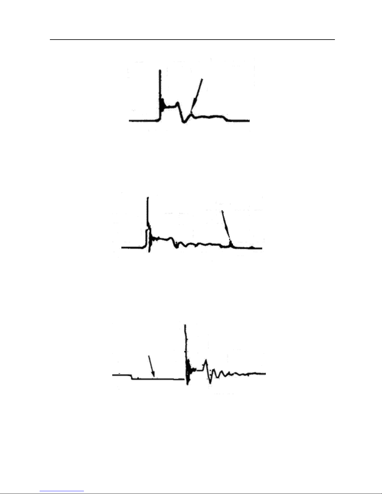
The waveform shown on Fig. 4-6, appears a lot of clutter on the contact break
point, which is obviou
sly caused by the serious erosion on contact break point.
It can be verified via burnishing the contact or changing the circuit breaker.
Fig. 4-6
For the primary voltage waveform shown on Fig
. 4-7, the damped attenuation
cycles obviously reduced on the spark period, the amplitude became lower,
which is evidently caused by capacitor leakage.
24
Page 27
LAUNCH X431 PAD Scopebox User’s Manual
Fig. 4-7
The waveform on Fig. 4-8, shows the accide
ntal pumping during contact
closing period. The irregular beating is caused by insufficient spring force.
Fig. 4-8
The curve on Fig. 4-9 shows the contact angle is too small during the
magnetizing per
iod, which is caused by too large contact gap.
Fig. 4-9
A lot of clutter will be display ed on the horizont
al section of primary waveform if
contact has poor grounding, as shown below figure 4-10.
25
Page 28

LAUNCH X431 PAD Scopebox User’s Manual
Fig.4-10
Fig. 4-11 shows the fault of low-voltage waveform in electronic ignitio
n system.
The voltage does not rise during magnetiz ing, w hich ind icates that the effect of
limitation of the circuit failed and no components on distributorless ignition
system can be adjusted. When this waveform is abnormal, you can only
replace the ignition coils, igniter, ignition signal generator and cam position
sensor, etc., one by one, to find out the faulty component or module.
Fig. 4-11
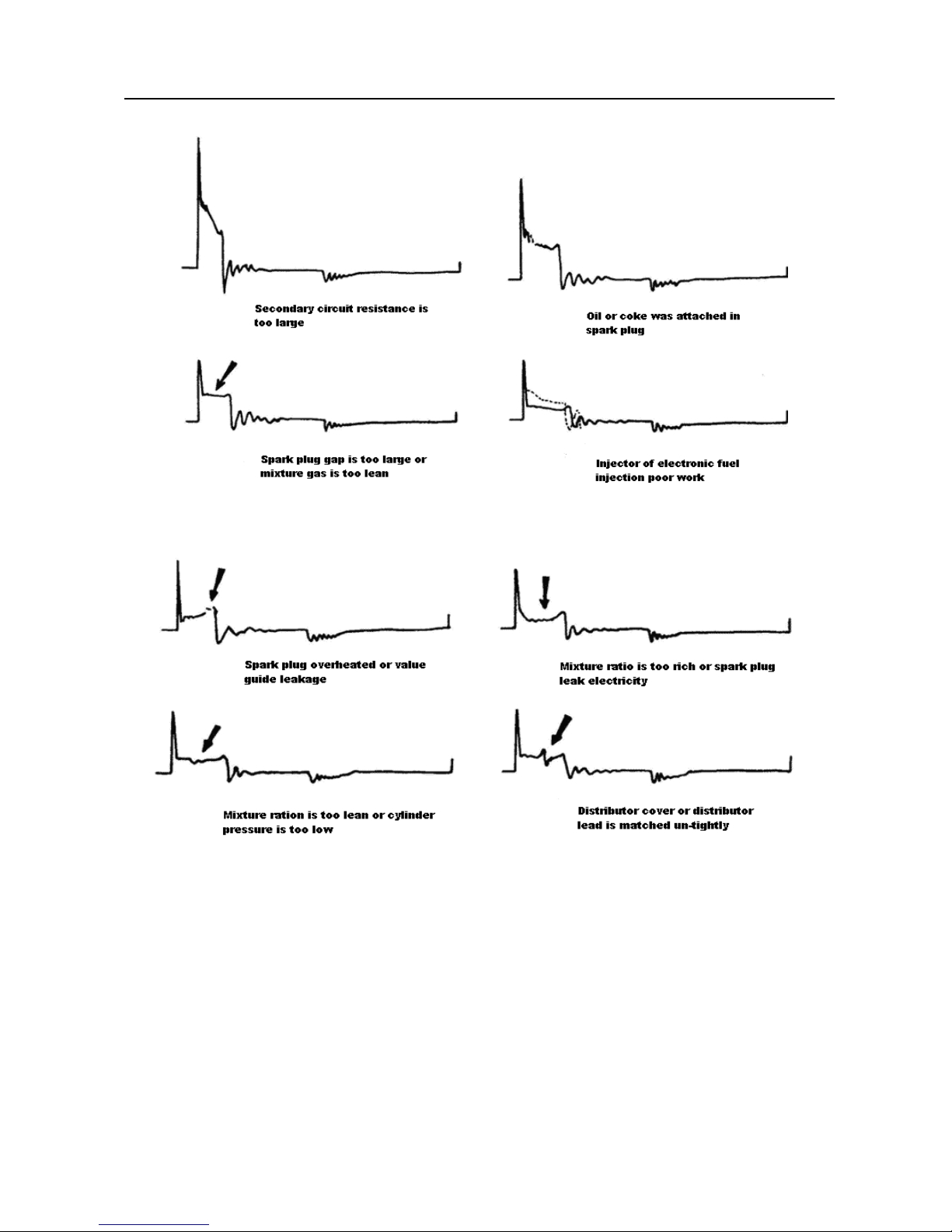
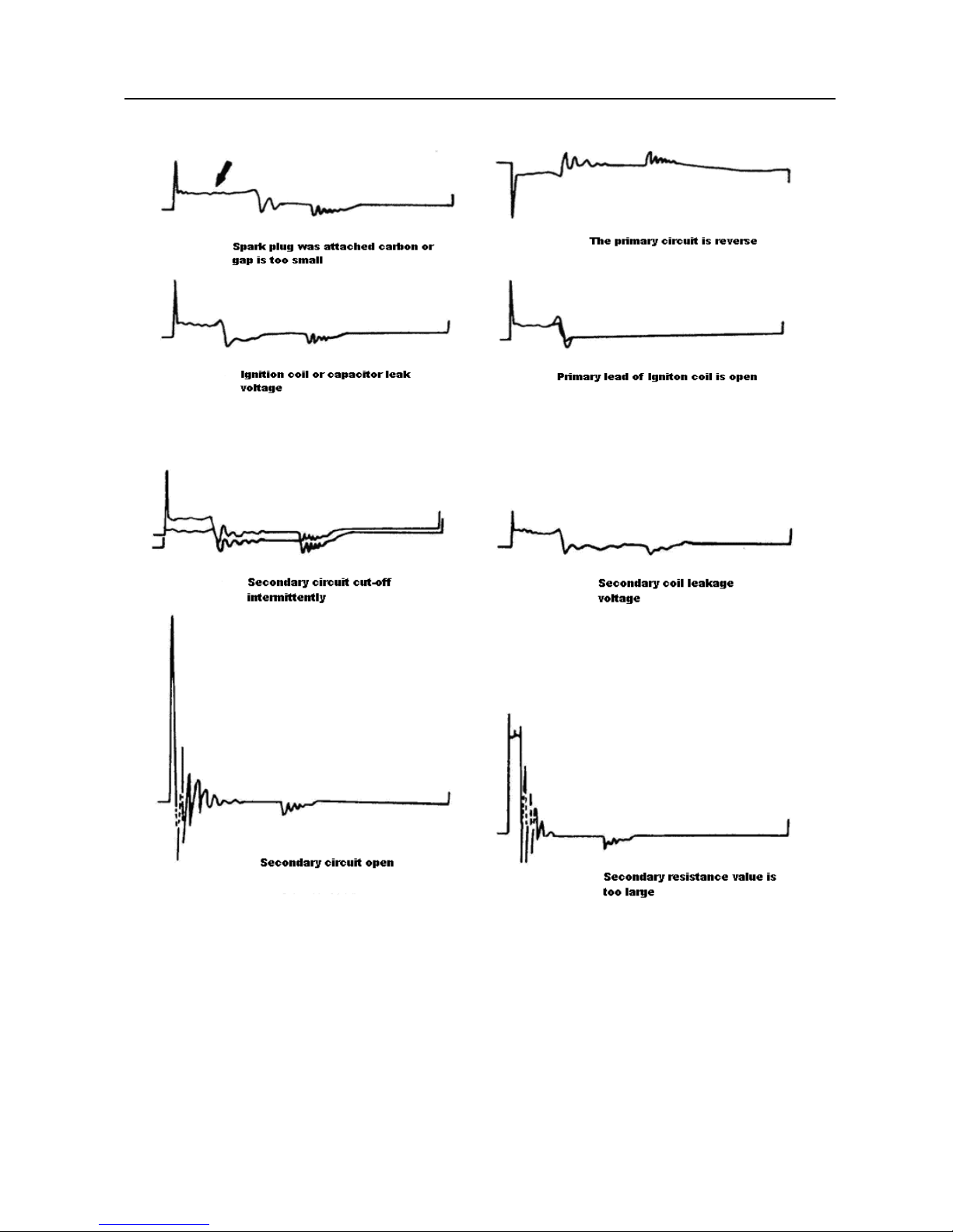
The secondary waveform is also affected by the spark plug, the combustion
process, mixt
ure gas composition, the engine thermal state of the ignition coil,
etc., which is more complicated. The following lists a large number of
measured secondary faulty waveform for reference. Since various factors lead
to the failures, Fig. 4-12 just shows the major possible factors for the failures.
26
Page 29
LAUNCH X431 PAD Scopebox User’s Manual
27
Page 30
LAUNCH X431 PAD Scopebox User’s Manual
Fig 4-12
28
Page 31

LAUNCH Android-based Scopebox User’s Manual
1 Foreword
1.1 Introductions
The scopebox is an optional add-on module for Launch’s
Android-based diagnostic tool, including automotive oscilloscope and
automotive ignition waveform.
Automotive oscilloscope can make the auto repair technician quickly judge
the faults on automotive electronic equipment and wiring, and the
oscilloscope sweep speed is far greater than the signal frequency of such
vehicles, usually 5-10 times of the measured signal. The automotive
oscilloscope not only can quickly acquire the circuit signal, but also can
slowly display the waveform to observe and analyze. It can also record and
store the tested signal waveform which can be recalled to observe for the fast
signal, having great convenience to failure analysis. Either high-speed signal
(e.g.: Injection nozzle, intermittent fault signal) or the slow-speed signal (e.g.
the throttle position change and the oxygen sensor signal) can be observed
through automotive oscilloscope in an appropriate waveform.
The electronic signal can be compared and judged via measuring five
parameters indexes. The five parameters are the amplitude (the maximum
voltage of signal), the frequency (the cycle time of signal), the shape (the
appearance of signal), the pulse width (the duty cycle or the time range of
signal), and the array (the repetition characteristic of signal), which can be
tested, displayed, saved by the automotive oscilloscope. Via the waveform
analysis can further detect the circuit fault on sensors, actuators, circuits, and
electronic control units, etc.
1.2 Product features
y Rapidly capture the circuit signal.
y Display waveform slowly for observation and analysis.
y Record and store the tested signal waveform for playback and failure
analysis.
y Detect, display and store all the electrical signal of five parameters, namely
Page 32

LAUNCH Android-based Scopebox User’s Manual
ampl
itude, frequency, shape, pulse width, and array.
1.3 Product function
Provides sp
ecialized automotive oscilloscope function and supports ignition
waveform analysis.
1.4 Technical parameters
Scopebox: 4 channels, highest sampling frequency 200MHZ, max. storage
depth 64MSa, 8-bit resolut ion.
Page 33

LAUNCH Android-based Scopebox User’s Manual
2 Structure and Accessories
2.1 Scopebox structure
Fig 2-1 Sc
opebox Structure Diagram
Table 2-1 sh ows the ports and indicators for the scopebox.
No. Name Description
1 CH1 Channel 1
2 CH2 Channel 2
3 CH3 Channel 3
4 CH4 Channel 4
5 External trigger External trigger signal
6 Fixed signal
generator
Generate a square signal with fixed 1K frequency.
Page 34

LAUNCH Android-based Scopebox User’s Manual
7
Power indicator It keeps steady red after the scopebox is powered
on.
8 Running
indicator
It remains steady green after the scopebox is
running.
9 Communication
indicator
It blinks in process of data commu nication.
10 Power interface Connect to power supply via the power adapter.
11 B-shaped USB
interface
Connect main unit via USB cable as separated
individual USB devices.
2.2 Scopebox accessories
The scopebox includes the sec ondary pickup c able for 4-chann el osc illoscope ,
crocodile clips for 4-channel oscilloscope, etc. See Tabl e 2-2.
As the product configuration can be different, the accessories included with the
product may differ from the accessories listed on this manual. Please see the
packing list attached to the product for the detailed a ccessories.
Table 2-2 Accessory checklist
No. Name Picture
1 Secondary ignition pickup for
4-channel oscilloscope
2 Crocodile clips for 4-channel
oscilloscope
3 Direct ignition extension cord
Page 35

LAUNCH Android-based Scopebox User’s Manual
4
6-way universal guide line for
4-channel oscilloscope
5 BNC to 4mm connector test cable
6 Pin connector suite for 4-channel
oscilloscope
Page 36

LAUNCH Android-based Scopebox User’s Manual
3 Automotive Oscilloscope
3.1 Connection
The scopebox should work with the Launch’s Android-based diagnostic tool.
1. Firstly, power on the diagnostic tool.
2. Then plug one end of ground cable of the scopebox into external trigger
channel (GND), the other end should b e grounded.
3. Connect one end of probe cable to the CH1, CH2, CH3, or CH4 on the
scopebox, and then connect the other end to related signal terminal.
Warning: Please use the specific capacitance probe when diagnosing the
ignition high voltage line. Never connect the scopebox to the ignition
secondary circuit directly.
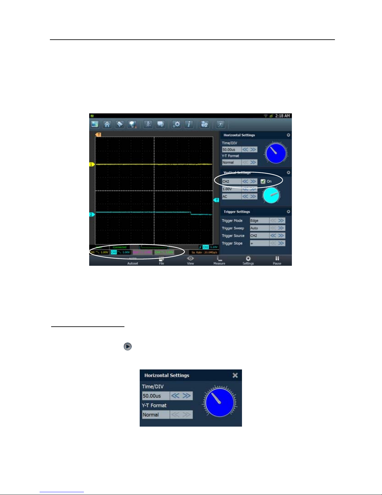
3.2 Initial interface introduction
Fig. 3-1 displays the initial interface of the scopebox.
Fig. 3
-1
Page 37

LAUNCH Android-based Scopebox User’s Manual
No. Descri
ptions
1 Signal display area
2 Horizontal Settings: Controls the time base.
3 Vertical Settings: Controls the amplitude of the displayed signal.
4 Trigger Settings: Controls the start event of the sweep.
5 Channel Selection Button
6 Function Menu
[Auto]: It indicates auto trigger setting. See Chapter 3. 3.2.
[Ref]: There are expert reference and base reference
available. Expe rt reference enables you to re call your customized
expert database, whereas base reference provides automatic
pre-setting function of specialized sensors. See Chapter 3.3.6.
[File]: Provides save snapshot, snapshot manager, waveform
record and waveform replay. See Chapter 3.3.5.
[View]: Calibration and display settings are available. See
Chapter 3.3.3.
[Measure]: Includes signal source measurement, horizontal
measurement, vertical measurement and clear measurement. See
Chapter 3.3.4.
[Settings]: Shows/hides the parameter settings area
including horizontal settings, vertical settings and trig ger settings.
/ [Start/Stop]: Starts/stops collecting waveforms.
Page 38

LAUNCH Android-based Scopebox User’s Manual
3.3 Operations
3.3.1 Channel selection and attributes setting
<1> Channel selection
There are two ways av ailable for channel s election: (See Fig. 3-2)
A. Select from the channel tab shown at the bottom of the waveform display
area;
B. Select from Vertical settings.
Note: For better comparison and identification, each channel and waveform
are marked in different colors.
Fig.3
-2
<2> Channel attributes & trigger setting
Channel attributes can be set via horizontal settings and vertical settings.
Horizontal Settings
User can make some settings directly by tapping < or > next to options. See
Fig. 3-3.
Page 39

LAUNCH Android-based Scopebox User’s Manual
Fig. 3
-3
Options descriptions:
Menu Comments/Settings
Time/DIV
Horizontal sc ale. I f t he w aveform acquisition is stopped
(using the
/ button), the Time/DIV selector
expands or compresses the waveform.
Y-T format
The conventional oscil loscope display format. It shows
the voltage of a waveform record (on the vertical axis)
as it varies over time (on the horizontal axis).
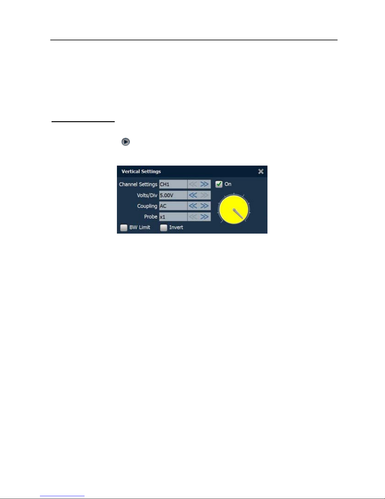
Vertica
l Settings
The trigger determines when the scopebox starts to acquire data and display a
waveform. When a trigger is set up properly , it can conver t unstable displa ys or
blank screens into meaningful waveforms.
When the scopebox starts to acquire a waveform, it collects enough data so
that it can draw the waveform to the left of the trigger point. The scopebox
continues to acquire dat a w hile waiting for the trigger condition to occur. After it
detects a trigger, the scopebox continues to acquire enough data so that it can
draw the waveform to the right of the trigger point.
User can make some settings directly by tapping < or > next to options. See
Fig. 3-4.
Page 40

LAUNCH Android-based Scopebox User’s Manual
Fig. 3
-4
Options descriptions:
Menu Comments/Settings
Channel
To select the channel source.
Volts/DIV
It is defined as “Volts/Division” and mainly used to
change the resolution.
Coupling
Trigger coupling determines what part of the signal
passes to the trigger circuit. AC, DC and Ground are
included:
AC: Blocks the DC component of the input sign al;
DC: Passes both AC and DC components of the input
signal;
Ground: Disconnects the input signal.
Probe
When using a probe, the scopebox allows you to select
the attenuation factor for the probe. The attenuation
factor change s the vertica l scaling of t he scopebox so
that the measurement results reflect the actual voltage
levels at the probe tip.
BW Limit
ON: Limits the channel bandwidth to 20MHz to redu ce
display noise.
OFF: Get full bandwidth.
Invert ON: Turn on the invert function.
Page 41

LAUNCH Android-based Scopebox User’s Manual
OF
F: Restore to the ori gi nal display of the wa veform.
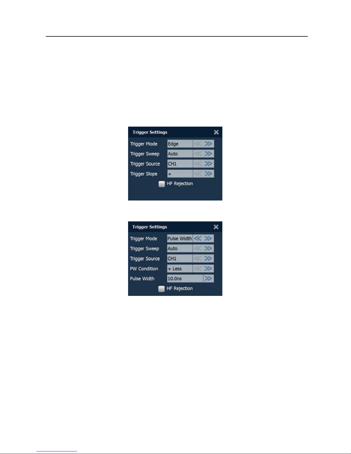
T ri
gger setting
Trigger indicates that when certain waveform meets the conditions that are
predefined according to the requirements, the scopebox acquires the
waveform and its adjacent section, and then presents it on the screen.
Fig. 3-5
1) If Edg
e trigger is selected (An edge trigger determines whether th
e
scopebox finds the trigger point on the rising or the falling edge of a signal.):
Menu Comments/Settings
Sweep
The sweep mode determines how the scopebox
behaves in the absence of a trigger event. The
scopebox provides three trigger modes: Auto, Normal,
and Single.
Auto: It allows the scopebox to acquire waveforms
even when it does not detect a trigger condition. If no
trigger condition occurs while the scopebox is waiting
for a specific pe r iod, it will force it self to trigger.
When forcing invalid triggers, the scopebox can not
synchronize the wa veform, and then waveform seems
to roll across the display. If valid triggers occur, the
Page 42

LAUNCH Android-based Scopebox User’s Manual
display becomes stable on the screen.
Normal: This mode allows the scopebox to acquire a
waveform only when it is trig gered. If no trigger occurs,
the scopebox keeps waiting, and the previous
waveform, if any, will remain on the display.
Single: In this mo de, it only acquires the waveform that
generates for the first time the trigger conditions are
met, and then stops after finishing capture.
Source
Select which channel as trigger signal.
Slope
+ : Trigger on rising edge
- : Trigger on falling edge
High Freq
Rejection
Reject high frequency signals when selected.
2) If Pulse Width trigger is selected (Pulse trigger occurs according to the
wi
dth of pulse. The abn ormal signals can be detected thro ugh setting up the
pulse width condition):
Menu Comments/Settings
Sweep
The sweep mode determines how the scopebox
behaves in the absence of a trigger event. The
scopebox provides three trigger modes: Auto, Normal,
and Single.
Auto: It allows the scopebox to acquire waveforms
even when it does not detect a trigger condition. If no
trigger condition occurs while the scopebox is waiting
for a specific period, it will force itself to trigger.
When forcing invalid triggers, the scopebox can not
synchronize the wa veform, and then waveform seems
to roll across the display. If valid triggers occur, the
display becomes stable on the screen.
Normal: This mode allows the scopebox to acquire a
Page 43

LAUNCH Android-based Scopebox User’s Manual
waveform only when it is trig gered. If no trigger occurs,
the scopebox keeps waiting, and the previous
waveform, if any, will remain on the display.
Single: In this mo de, it only acquires the waveform that
generates for the first time the trigger conditions are
met, and then stops after finishing capture.
Source
Select which channel as trigger signal.
Condition
To select pulse condition.
Pulse Width
Set required pulse width.
High Freq
Rejection
Reject high frequency signals when selected.
3.3.2 Auto
The scopebox has an Auto feature that sets up the scopebox autom atically to
display the input signal in a best fit.
Tap
, the scopebox may change the current settings to display t he signal.
It automatically adjusts the vertical and horizontal scaling, as well as the trigger
coupling, position, slope, level and mode settings.
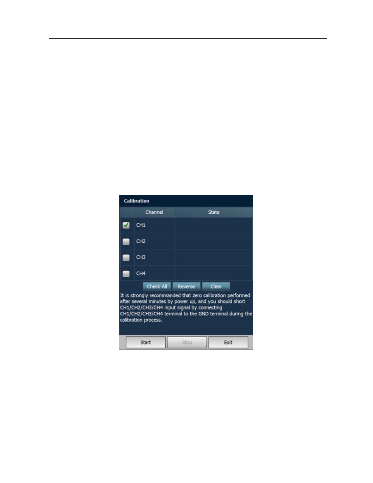
3.3.3 View Settings
<1> Calibration
This option adjusts the scopebox’s internal circuitry to get the best accuracy.
Use this function to calibrate the Scopebox’s vertical and horizontal systems.
Tap
and then tap [Calibration], a dialog box similar to Fig. 3-6 will appear.
Page 44

LAUNCH Android-based Scopebox User’s Manual
Fig. 3-6
Check the box before the channel to select it. To deselect it, just uncheck it.
After choosing the desired channel(s), tap [Start] to start calibration and [Start]
button will be temporarily invalid during calibrating. Tap [Stop] to stop
calibrating. Once it becomes active, it indicates calibration has completed.
Notes: In proc ess of cali bration, make sure CH1/ CH2/CH3/CH4 has no signal
input. Moreover, calibration may take several minutes and please be patient to
wait.
<2> REF settings
Reference waveforms are saved waveforms to be selected for display. The
reference function will be available after saving the selected waveform to
non-volatile memory.
Tap
and then [REF] to enter the REF setting screen. See Fig. 3-7.
Page 45

LAUNCH Android-based Scopebox User’s Manual
Fig. 3
-7
Tap < or > to select the desired reference value for time/DIV and volts/DIV. To
show or hide the REF, just check/uncheck the box before On/Off.
<3> Display settings
Tap
and then [Display settings] to enter the setting screen. See Fig. 3-8.
Fig. 3-8
Select “Vectors” or “Dots” to display waveforms as vectors or dots.
Check/uncheck the box before Grid to turn on/off grid display.
3.3.4 Measure
<1> Channel source
Tap
and then [Source], a screen similar to Fig. 3-9 will appear.
Page 46

LAUNCH Android-based Scopebox User’s Manual
Fig. 3-9
<2> Horizontal / Vertical measure
Horizontal Measure / Vertical Measure are used to measure voltage parameter
and time parameter respectively. Drag A line upwards or downwards to control
voltage. Move A line left or right to fine-tune timebase. A line is a solid line and
B line is a dotte d line.
Tap
and then [Horizontal Measure], a screen similar to Fig. 3-10 will
appear.
Fig. 3-
10
Page 47

LAUNCH Android-based Scopebox User’s Manual
Not
e: If no desired channel is selected, the sy st e m will take t h e cu rr ent so u rce
as the default channel.
<3> Clear measure
Tap
and then [Clear Measure], the system will clear the measurement
result on screen.
3.3.5 File management
<1> Save snapshot
While viewing sampling data, tap
and then [Save Snapshot] to store the
current screen.
<2> Snapshot manager
While viewing sampling d ata, tap
and then [Snapshot Manager] to enter.
View, delete and edit operations are supported.
<3> Record waveform
This function is used to record input waveforms that are acquired by the
scopebox at a specific period, and save it as waveform file which can be
recalled in future.
It can be performed only w hen the scop ebox is coll ecting dat a in Norm al mode.
Tap
, then select [Record] from the pop-up menu to start recording. See
Fig. 3-11.
Page 48

LAUNCH Android-based Scopebox User’s Manual
Fig.3
-11
Tap [Start] to start recording with a minimum record length of 10 frames, and
[Stop] to stop recording. While recording, the recorded pages will be shown on
the screen.
<4> Load waveform for playback
The Import function enables you to import the stored waveform file for
playback and review. During replaying, the scopebox stops collecting data
automatically.
Tap
, then select [Waveform replay] from the pop-up menu to enter a
screen similar to Fig. 3-12.
Page 49

LAUNCH Android-based Scopebox User’s Manual
Fig.3
-12
Select the file first, and then tap
to open the waveform file. Tap to
starting the playback and tap
to stop it.
Fig.3
-13
To delete the waveform file, tap
.
Tap
to return to the previous screen.
Page 50

LAUNCH Android-based Scopebox User’s Manual
3.3.6 Expert Reference
<1> Expert Reference
By default, it appears blank. As a matter of fact, Ex pert reference database i s
generated by doing the fol lowi ng:
1. Open and edit a snapshot
;
2. Select “Joint the expert database” (refer to the following illustration), and
then tap
to save the waveform being displayed on the screen as REF.
Fig. 3-
14
Tap
and then [Expert Reference] to enter, the following operation can be
done:
: To load and recall the selected file.
: To delete the selected file.
: To edit the selected file.
<2> Base Reference
Preset waveforms of some sensors are available f or your reference.
Page 51

LAUNCH Android-based Scopebox User’s Manual
Fig. 3-15
3.3.7 Exit the application
Tap to exit the current appli c ati on.
Page 52

LAUNCH Android-based Scopebox User’s Manual
4 Automotive Ignition waveform
The ignition system is the system which has greatest impact on the
performances of gasoline engine, as the statistical data shows that nearly half
of the failures are caused by poor work of electrical system. And the
performance tests of engine often start from the ignition system. Nowadays
ignition system includes distributor and distributorless. Distributorless includes
independent ignition and simultaneous ignition.
1. Distributor ignition system i.e. contact breaker with contact-controlled
ignition system (commonly known as the platinum) and contact breaker
with noncontact-controlled ignition system combined with magnet, hall
components or infrared.
2. Independent ignition system: Each spark plug has its own individual coil
that sits right on top of it, also called coil on plug system. Crankshaft
sensor send out the ignition timing signal and cylinder identification signal
so that the ignition system can send out ignition signal to specifie
d
cylinder in specified time , each cylinder has its independent ignition coil.
3. Simultaneous ignition system: Two spark plugs share the same coil, also
called waste spark system. When two cylinder pistons reach top dead
center at the same time (one is compression, another is the exhaust), two
spark plugs will be ignit ed at the same time, at this time, the ignition for
the former cylinder is in high-p ressure low temperature gas mixture, th
e
ignition is val id, while for th e lat ter one is in low-pressure high te mperature
exhaust gas, the ignition is invalid.
The scopebox can test and analyze the secondary signal for various engine
ignition systems.
4.1 Secondary-distributor ignition analysis
Connections: Plug the BNC end of secondary ignition pickup into
CH1/CH2/CH3/CH4 channel of the scopebox, and then connect the
high-voltage clip to high-voltage line, and crocodile clips to ground.
Tips: Common ignition sequence (the specific sequence is subject to the
Page 53

LAUNCH Android-based Scopebox User’s Manual
actua
l engine ignition sequence)
Four-stroke in-line four-cylinder: 1-2-4-3, or 1-3-4-2
Four-stroke in-line six-cy linder: 1-5-3-6-2-4, or 1-4-2-6-3-5
Four-stroke in-line eight-cylinder: 1-8-4-3-6-5-7-2
Five-cylinder: 1-2-4-5-3
V 6 engine: Generally speaking, based on the person sitting on the driver cab,
if the right side cylinder numbers on the right side, from the front to the back
are as follows: 1, 3, 5; and the cylinder numbers on the left side, from the front
to the back are as follows: 2, 4, 6; then the ignition sequence is: 1-4-5-2-
3-6. If the cylinder numbers on the righ t side, fr om the front to the back are as
follows: 2, 4, 6; and cylinder numbers on the left side, from the front to the back
are as follows:1, 3, 5; then the ignition sequence is: 1-6-5-4-3-2.
The Figure 4-1 below show s the nor mal ignition waveform of distributor ignition
system, the upp er one is the secondary waveform, an d the lower one is the
primary waveform.
The secondary waveform
A se ction is co ntact open period; B sectio n is make contact period, which is the
magnetizing field of ignition coil.
Page 54

LAUNCH Android-based Scopebox User’s Manual
Fig. 4
-1
1) Contact break point: The primary circuit of ignition coil cut off, the
secondary voltage was sensed and increased sharply
2) Ignition voltage: Secondary coil voltage overcome the damper of high
voltage line, the contact breaker gap and the spark plug gap to release
magnetizing energy, 1-2 section is the breakdown voltage
3) Spark voltage: For the capacitor disch a rge vol tage
4) Ignition voltage pulse: For the charge and discharge section s
5) Spark line: The inductance discharge process, i.e. the mutual inductance
voltage of ignition coil maintains the conduction of secondary circuit
6)
Contact point close the current flow into primary coil, the primary coil
oscillates due to the mutual inductance.
Primary ignition waveform
Section a shows the voltage oscillation on the primary circuit due to the
magnetic induction of spark in the duration;
Section b shows the damped oscillation g enerated by remaining m agnetic field
Page 55

LAUNCH Android-based Scopebox User’s Manual
energy
after the spark;
Section c shows the make contact magnetic period of primary coil.
Seen from the waveform, the amplitudes of breaker contact closed angle,
break angle and breakdo wn vol tage and spark voltage are v ery cl ea r, besides,
the spark delay period and t wo oscill ation s can also be test ed. For the ig nition
system without faults, compared with the whole cycle, the contact closed angle
just 45%-50% (four-cylinder), 63%-70% (six-cylinder), or 64%-71%
(eight-cyliner); the breakdown voltage is over 15kv; the spark voltage is about
9kV, the spark period is greater than 0.8ms. If these values or waveform are
abnormal, it means there is fault or the system needs to be adjusted.
4.2 Secondary-simultaneous ignition analysis
Connections: Plug the BNC end of secondary ignition pickup into
CH1/CH2/CH3/CH4 channel of Scopebox, then connect the high-voltage clip
to high-voltage line, and crocodile clips to ground.
Connection as shown in figure 4-2:
Fig. 4
-2
Page 56

LAUNCH Android-based Scopebox User’s Manual
F
ig. 4-3 below shows the valid and invalid ignition waveforms. Under the
working status of valid ignition, the breakdo wn voltage and spark voltage are
higher because the cylinder is filled with fresh combustible mixture gas, which
has a lower ioni zation level and vice versa.
Fig. 4
-3
4.3 Secondary-direct ignition analysis
Connection:
1) When the high-voltage wire is exposed, plug the BNC end of secondary
ignition pickup into CH1/CH2/CH3/CH4 channel of Scopebox, then
connect the high-voltage clip to high-voltage line, and crocodile clips to
ground.
2)
If no high-voltage wire exposes, dismantle ignition coil of tested cylinder
and use direct ignition extension cord. Connect one end to ignition coil
which should be grounded via direct ignition grounding wire, and insert the
other end into cylinder to joint with spark plug. Then plug the BNC end of
secondary ignition pickup into CH1/CH2/CH3/CH4 channel of Scopebox,
then connect the high-voltage clip to high-voltage line, and crocodile clips
to ground.
Connections are shown in Fig. 4-4:
Page 57

LAUNCH Android-based Scopebox User’s Manual
Fig. 4
-4
Fig. 4-5 shows the normal secondary (the upper one) and (the lower one)
primary ignition waveform of direct ignition system. Because the on/off of
primary circuit is not opening/c losing of mechanical cont act, but the conduction
of transistor. The primary voltage has no obvious oscillations within the
duration, but the voltage increases during the magnetization process due to
current limiting, and this change can cause corresponding fluctuations of
secondary voltage line as a result of induction of igniti on co il .
Page 58

LAUNCH Android-based Scopebox User’s Manual
Fig. 4
-5
4.4 Waveform analysis mode
The ignition secondary si ng l e -cyl i nd er wave f orm test is mainly used to:
a. Analyze the ignition dwell angle of single cylinder.(ignition coil charging
time)
b. Analyze the capability of ignition coil and secondary high tension circuit
(from ignition line to ignition voltage line).
c. Find the improper mixture A/F ratio of single cylinder (from combustion
line).
d. Analyze the capability of capacitance (platinum or ignition system).
e. Find the spark plug that causes misfire of the cylinder (from combustion
line).
This test can provide very meaningful information about the combustion quality
for each cylinder. If necessary, this test can also be performed during driving.
Since the secondary ignition waveform is significantly affected by different
engines, fuel systems and ignition condi tions, it is useful for detecting the fault s
Page 59

LAUNCH Android-based Scopebox User’s Manual
of eng
ine mechanical parts, fuel system components, and ignition system
components. Different parts of the waveform can specify that some
components and systems on the specific cylinder have faults. Refer to the
instructions for various parts of waveform for the related component working
status of specific waveform secti o n.
Test methods and conditions:
Start the engine or drive the vehicle accroding to the driving performance faul t
or poor ignition, etc. Confirm the consistence of judgement standard (the
amplitude, frequency, shape and pulse width, etc., for each cylinder), check
the fault of the waveform for corresponding components.
Waveform results: Observe the ignition coil at the b eginning of charging, the
relative consistent falling edge re presen t s the dwell angle and ignition timing of
each cylinder are precise.
Ignition line:
Observe the height consistence of flashover voltage. Too high flashover
voltage (even out of the scopeb ox screen) re presents a high re sist ance existed
in the ignition secondary circuit (for example, open circuit, or damaged spark
plug or high v oltage line, or too large time g ap on spark plug), while the to o
short sparking voltage represents the resistance of ignition secondary circuit is
lower than normal value (due to pollutant and broken spark plug or the high
voltage line of spark plug has electrical leakage, etc.).
Spark or combustion voltage:
Observe the consistence of spark or combustion voltage, as it represents the
consistence of spark plug and the air-fuel ratio of each cylinder. In case that
the mixing ratio is too lean, the combustion voltage will be lower than normal
value.
Combustion line:
Observe the spark or the combustion line which shall be clean with few clutter,
as lots of clutter indicates the cylinder has poor ignition due to ignite too early,
damaged nozzle, pollutant spark plug, or other reasons. The duration of
combustion line indic ates the mixing ratio of the cylinder is abnormal l ean or
Page 60

LAUNCH Android-based Scopebox User’s Manual
ri
ch. Too long combustion line (usually greater than 2ms) represents the mixing
ratio is rich, whereas too short of combustion line (usually less than 0.75ms)
represents the mixing ratio is lean.
Ignition coil oscillation :
Observe at least two oscillation waveforms after the combustion line, which will
be better if more than three oscillation waveforms, as it represents the i gniti on
coil and capacitor (on Platinum or ignition system) are normal.
Primary voltage analysis
According to the faulty primary voltage waveform collected by the ignition
analysis, the related components and mechanical equipment status of ignition
system electrical circuit can be analyzed, which provides a reliable basis for
the adjustment and maintenance of power circuit to avoid the blind demolition.
The waveform shown on Fig. 4-6, appears a lot of clutter on the contact break
point, which is obviously caused by the serious erosion on contact break point.
It can be verified via burnishing the contact or changing the circuit breaker.
Fig. 4
-6
For the primary voltage waveform shown on Fig. 4-7, t he damped attenuation
cycles obviously reduced on the spark period, the amplitude became lower,
which is evidently caused by capacitor leakage.
Page 61

LAUNCH Android-based Scopebox User’s Manual
Fig. 4
-7
The waveform on Fig. 4-8, shows the accidental pumping during contact
closing period. The irregular beating is caused by insufficient spring force.
Fig. 4
-8
The curve on Fig. 4-9 shows the contact angle is too small during the
magnetizing period, which is caused by too large contact gap.
Fig. 4
-9
A lot of clutter will be displayed on the horizontal section of pr ima ry wave form if
contact has poor grounding, as shown below figure 4-10.
Page 62

LAUNCH Android-based Scopebox User’s Manual
Fig.4
-10
Fig. 4-11 shows the fault of low-voltage waveform in electronic ignition sys tem.
The voltage does not rise during magnetizing, which indicates that the effect of
limitation of the circuit failed and no components on distributorless ignition
system can be adjusted. When this waveform is abnormal, you can only
replace the ignition coils, igniter, ignition signal generator and cam position
sensor, etc., one by one, to find out the faulty component or module.
Fig. 4-1
1
The secondary waveform is also affected by the spark plug, the combustion
process, mixture gas composition, the engine thermal state of the igniti on coil,
etc., which is more complicated. The following lists a large number of
measured secondary faulty waveform for reference. Since various factors lead
to the failures, Fig. 4-12 just shows the major possible factors for the failures.
Page 63

LAUNCH Android-based Scopebox User’s Manual
Page 64

LAUNCH Android-based Scopebox User’s Manual
Fig 4-
12
Page 65

LAUNCH X431 GDS Scopebox Manual
1 Foreword
1.1 Introductions
X-431 GDS is a new generation of sophisticated and
integrated automotive diagnostic product with colorful screen
and powerful functions developed by LAUNCH, and Scopebox
is an optional function box for GDS, including automotive
oscilloscope and automotive ignition waveform.
Automotive oscilloscope can make the auto repair technician quickly
judged the faults on automotive electronic equipment and wiring,
and the oscilloscope sweep speed is far greater than the signal
frequency of such vehicles, usually 5-10 times of the measured
signal. The automotive oscilloscope not only can quickly capture the
circuit signal, but also can slowly display the waveform to observe
and analyze. It can also record and store the tested signal waveform
which can be played back to observe for the fast signal, having great
convenience to failure analysis. Either high-speed signal (e.g.:
injection nozzle, intermittent fault signal) or the slow-speed signal
(e.g. the throttle position change and the oxygen sensor signal) can
be observed through automotive oscilloscope in an appropriate
waveform.
The electronic signal can be compared and judged via measuring
five parameter
s indexes. The five parameters indexes are the
amplitude (the maximum voltage of signal), the frequency (the cycle
Page 66

LAUNCH X431 GDS Scopebox Manual
time of signal), the shape (the appearance of signal), the pulse width
(the duty cycle or the time range of signal), and the array (the
repetition characteristic of signal), which can be tested, displayed,
saved by the automotive oscilloscope. Via the waveform analysis
can further detect the circuit fault on sensors, actuators, circuits, and
electronic control units, etc.
1.2 Product features
z Rapidly capture the circuit signal.
z Display waveform slowly for observation and analysis.
z Record and sto
re the tested si
gnal waveform for playback and
failure analysis.
z Detect, display and store all
the electrical signal of five
parameters, namely amplitude, frequency, shape, pulse width,
and array.
1.3 Product function
Provides specialized automotive oscilloscope function and supports
ignition waveform analysis.
1.4 Technical parameters
Scopebox: 4 channels, highest sampling frequency 150MHZ, max
storage depth 64MSa, 8-bit resolution
Page 67

LAUNCH X431 GDS Scopebox Manual
2 Structure and Accessories
2.1 Scopebox structure
cture Diagram
Table 2-1 shows S Scopebox
Fig 2-1 Scopebox Stru
the ports and i
ndicators for X-431 GD
No. Name Description
1 CH1 Channel 1
2 CH2 Channel 2
3 CH3 Channel 3
4 CH4 Channel 4
5 External trigger External trigger signal
Page 68

LAUNCH X431 GDS Scopebox Manual
6 Fixed signal square signal with fixed 1K
generator
Generate a
frequency
7 Power indicator Oscilloscope power indicator, which will
be steady red after the oscilloscope is
powered on
8 Operating
indicator
The indicator will be steady green after
the oscilloscope operated.
9 Communica
indicator
tion After the data communication, the
indicator will blink (Green).
10 Power interface Connect to power supply via the power
adapter.
11 B-shaped USB
interface
Connect main unit via USB connect line
as separated individual USB devices
.2 S x acc
kup cable for 4-channel
nel oscilloscope, etc. See
th the product may differ from the accessories listed on
2 copebo essories
Scopebox includes the secondary pic
oscilloscope, crocodile clips for 4-chan
Table 2-2.
As the produc
t configuration can be different, the accessories
included wi
this manual. Please see the packing list attached to the product for
the detailed acc
essories.
Page 69

LAUNCH X431 GDS Scopebox Manual
Table 2-2 Accessory checklist
PictureNo. Name
1 Secondary ignition pickup for
4-channel oscilloscope
2 Crocodile clips for 4-channel
Oscilloscope
3 xtension cordDirect ignition e
4 6-way universal guide line for
4-channel oscilloscope
5 BNC to 4mm connector test
cable
6 Pin connector for 4-channel
oscilloscope
Page 70

LAUNCH X431 GDS Scopebox Manual
3 Automotive Oscilloscope
3.1 Connection
X-431 GDS Scopebox should work with the X431 GDS main unit.
1. Firstly, power on the main unit (Connect one end of the power
adaptor into the
power interface of main unit, and the other end
to the DC 12V power supply. Alternatively it can be also powered
by cigarette lighter cable and double clip power cord).
2. Then pl
ug one end of ground cable of oscilloscope into external
trigger
chann
el (GND), the other end should be grounded.
3. Connect one end of probe cable of oscilloscope to the CH1, CH2,
CH3, or
CH4 on oscilloscope module, and then connect the
other end to related signal terminal.
Warning: please use the specific capacitance probe when
diag
nosing the ignition high voltage line. Never connect the
oscilloscope to the ignition secondary circuit directly.
3.2 Initial interface introduction
Fig. 3-1 displays the initial interface of oscilloscope.
Page 71

LAUNCH X431 GDS Scopebox Manual
Fig.3-1
Button descriptions:
[System]: includes show des
ktop, Wi-Fi setting, current version and
exit the program.
[Help]: displays help files.
[File]: s
upports import waveform, store waveform, store graphics,
record wavefor
m, print waveform, show/hide the grid, display cached
interface, turn pages, and clear.
[Trigger]: The following options are available: one-channel trigger /
alternation t
rigger, trigger channel source, trigger types, trigger
modes, horizontal trigger hold-off setting and auto calibration.
[Measure]: measures the ti
me and the voltage for the waveforms.
[Start/stop]: starts/stops col
lecting oscilloscope waveforms.
[Expert]: provides automatic pre-setting function of specialized
sensors.
Page 72

LAUNCH X431 GDS Scopebox Manual
3.3 Operations
3.3.1 Channel selection and attributes setting
<1> Channel selection
There are two ways available for channel selection.
A. Select from the channel menu;
B. Select via each channle attribute button.
See Fig. 3-2.
Fig.3-2
<2> Channel attributes setting
Each channel features five attributes.
A. Channel switch selection.
B. Channel voltage adjustment: + indicates increase voltage by one
level, while –
indicates decrease voltage by one level.
C. Channel time-base adjustment: + means to increase time-base
Page 73

LAUNCH X431 GDS Scopebox Manual
by one level and – means to decrease time-base by one level.
D. Channel phase selection: normal phase or reverse phase.
E. Channel coupling modes selection: DC, AC, or Ground.
See Fig.
3-3 and Fig. 3-4 for channel 1 & channel 4 attributes setting
interfaces re
spectively.
Fig.3-3 Channel 1 attributes setting
Page 74

LAUNCH X431 GDS Scopebox Manual
Fig.3-4 Channel 4 attributes setting
3.3.2 Trigger setting
<1> Trigger source
Single channel trigger and alternation trigger are included.
[Single channel trigger]: collects all channels data by triggering one
channel;
[Alternation trigger]: Each channel collects data separately based on
its own channel
triggering, only for AUTO mode.
Fig. 3-5 and Fig. 3-6 show single channel trigger & alternation trigger
setting interface
s.
Page 75

LAUNCH X431 GDS Scopebox Manual
Fig.3-5 Single channel trigger
Fig.3-6 Alternation trigger
<2> Trigger channel
To set trigger mode and voltage for one channel, please select this
channel first. See button
[Trigger].
Page 76

LAUNCH X431 GDS Scopebox Manual
<3> Trigger type
Includes edge trigger and pulse trigger, see button [Time base].
[Edge trigger]: Touch [edge] to select rising edge or falling edge;
[Pulse trigger]: Touch button [pulse] to select. There are 6 modes
available.
<4> T
rigger mode
It falls into: Auto, Normal and Single trigger. See button [Auto].
[Auto]: continuous trigger. Automatically trigger when it meets the
trigger
condit
ions; otherwise, the trigger will be forced by system;
[Normal]: continuous trigger. Trigger only when the trigger conditions
are met,
or else trigger does not happen.
[Single]: single trigger. Only trigger once when the trigger conditions
are met.
<5> Horizontal trigger hold-off setting
This option allows you to set the horizontal trigger position of the
oscilloscope. It
can be set by clicking the trigger icon directly or
through the menu. See Fig. 3-7.
Page 77

LAUNCH X431 GDS Scopebox Manual
Fig.3-7
In Fig. 3-7, the yellow inverted triangle is the horizontal hold-off
pointer. Butt
on [Hold-off 50%] can coarsely tune the horizontal
trigger, and make fine adjustment in the horizontal trigger hold-off
zone.
<6> Auto calibration
Click [Auto calibrated] button, the oscilloscope will perform automatic
calibration. [Auto calibrate
d] button will be temporarily invalid during
calibrating. Once it becomes active, it indicates calibration has
completed. See Fig. 3-8.
Page 78

LAUNCH X431 GDS Scopebox Manual
Fig .3-8
3.3.3 Channel measurement
<1> Timebase measurement
Fig.3-9
Page 79

LAUNCH X431 GDS Scopebox Manual
Button descriptions:
[Timebase]: used to s
elect mode. When it is displayed as timebase,
it is in time measurement mode;
[A line]: enables you to select A\B measurement line. The currently
selected line i
s a solid line;
Left\Right move: fine adjutme
nt button for timebase;
A\B line: time measurement line;
Measurement value display area: an area for displaying time
measu
reme
nt result.
<2> Voltage measurement
Fig.3-10
Button descriptions:
[Voltage]: u
sed to select mode. When it is displayed as Volt, it is in
voltage meas
urement mode;
Page 80

LAUNCH X431 GDS Scopebox Manual
[A line]: enables you to select A\B measurement line. The currently
selected line is a solid line;
[Up/Down]: fine adjut
ment button for voltage.
3.3.4 Expert settings
This option is specially designed to measure related vehicle sensors.
After selecting one sensor
, the osicilloscope will be preset based on
preset value of this sensor.
Click [Expert] to enter the expert setting interface. See Fig.3-11.
Fig.3-11
In Fig.3-11, left side lists sensor list and right side displays current
sample wavefor
m of selected sensor.
Page 81

LAUNCH X431 GDS Scopebox Manual
3.3.4 File management
<1> Store picture
This option is designed to save the currently displayed waveforms as
graphic file. It can be performed when the oscilloscope stops
collecting data.
Touch [File], then select [Store picture] from the pull-down list. See
Fig. 3-12.
Fig.3-12
<2> Store waveform
This item is to save the currently displayed waveforms as data file
which can be pl
ayed back by oscilloscope. It can be performed when
the oscilloscope stops collecting data.
Touch [File], then select [Store waveform] from the pull-down list.
See Fig. 3-13
.
Page 82

LAUNCH X431 GDS Scopebox Manual
Fig.3-13
<3> Record waveform
This function is used to record waveforms that are collected by
oscilloscope at
a period, and save it as data file which can be played
back in future.
It can be performed when the oscilloscope stops collecting data.
Touch [File], then select [Record] from the pull-down list to start
recording. See
Fig. 3-14.
Page 83

LAUNCH X431 GDS Scopebox Manual
Fig.3-14
[Record/Stop]: starts / stops recording. While recording, the recorded
pages will be sh
own on the screen.
<4> Import waveform for playback
The Import function enables you to import the stored waveform file
for playback and review. It only works when the oscilloscope stops
collecting data.
Click [File], then select [Import] from the pull-down list. See Fig.
3-15.
Page 84

LAUNCH X431 GDS Scopebox Manual
Fig.3-15
To delete a waveform file, please select it first, then touch [Delete]
button.
Click [OK] button to open th
e waveform file, then use channel
attributes settin
g to adjust the waveform display, or touch [File]
->[Pre Pg.]\ [Next Pg.] to turn pages. See Fig. 3-16.
Page 85

LAUNCH X431 GDS Scopebox Manual
Fig.3-16
<5> Print waveform
This option allows you to print the currently displayed waveform out
through a specific pr
inter. Before printing, make sure that the
oscilloscope stops collecting data and the printer is properly
connected.
Click [File], then select [Print] from the pull-down list. See Fig. 3-17.
Page 86

LAUNCH X431 GDS Scopebox Manual
Fig.3-17
<6> Show / hide the Grid
Click [File]>[Grid] button to show/hide grid. See Fig. 3-18.
Fig.3-18
Page 87

LAUNCH X431 GDS Scopebox Manual
<7> Display and Clear cached waveforms
This osicilloscope stores 10 pages of cached waveform data. While
in data collection stop mo
de, click [File], and then choose [Pre
Pg.]/[Next Pg.]/[Empty] from the pull-down menu to operate the
cached data. See Fig. 3-19.
Fig.3-19
3.3.5 System settings
Click [System] to enter system settings interface, similar to Fig. 3-20:
Page 88

LAUNCH X431 GDS Scopebox Manual
Fig.3-20
Button description:
[Show Desktop]: to return
to main menu screen
[Wi-Fi setting]: to configure Wi-Fi con
nection
[Version]: display the version information
[Exit prog
ram]: to exit this pr
ogram
View version information
In main menu, click [System], and then select [Version] to view the
current version
of the oscilloscope. See Fig. 3-21.
Page 89

LAUNCH X431 GDS Scopebox Manual
Fig.3-21
3.3.6 View help file
In main menu, click [Help] to enter a screen similar to Fig. 3-22.
Fig.3-22
Page 90

LAUNCH X431 GDS Scopebox Manual
4 Automotive Ignition waveform
The ignition system is the system which has greatest impact on the
performances of gasoline engine, as the statistical data shows that
nearly half of the failures are caused by poor work of electrical
system. And the performance tests of engine often start from the
ignition system. Nowadays ignition system includes distributor and
distributorless. Distributorless includes independent ignition and
simultaneous ignition.
1. Distributor ignition system i.e. contact breaker with
contact-contr
olled ignition system (commonly known as the
platinum) and contact breaker with noncontact-controlled
ignition system combined with magnet, hall components or
infrared.
2. Independ
ent ig
nition sy
stem: crankshaft sensor send out the
ignition timing signal and cylinder identification signal so that the
ignition system can send out ignition signal to specified cylinder
in specified time, each cylinder has its independent ignition coil.
3. Simultaneous ignition system: two cylinders share one ignition
coil, when two
cylinder pistons reach top dead center at the
same time (one is compression, another is the exhaust), two
spark plugs will be ignited at the same time, at this time, the
ignition for the former cylinder is in high-pressure low
temperature gas mixture, the ignition is valid, while for the latter
one is in low-pressure high temperature exhaust gas, the
Page 91

LAUNCH X431 GDS Scopebox Manual
ignition is invalid.
X-431 GDS can test and analyze the primary/secondary signal for
various engine i
gnition systems.
In main menu, click "Engine ignition waveform" - "Configuration" to
enter the interf
ace shown as Fig. 4-1:
Fig.4-1
This interface includes six engine ignition analyses:
Primary-Distributor ig
nition, Primary-Simultaneous ignition,
Primary-Direct ignition, Secondary-Distributor ignition,
Secondary-Simultaneous ignition, and Secondary-Direct ignition.
4.1 Primary-distributor ignition analysis
Tips:
Generally, the sequence of ignition is (The specific sequence is
Page 92

LAUNCH X431 GDS Scopebox Manual
subject to the actual engine ignition sequence)
Four-stroke in-line four-cylinder: 1—2—4—3, or 1—3—4—2
Four-stroke in-line six-cylinder: 1—5—3—6—2—4, or
1—4—2—6—3
—5
Four-s
troke in-line eight-cylinder: 1—8—4—3—6—5—7—2
Five-c
ylinder: 1-2-4-5-3
V 6 engine: generally speaking, based on the person sitting on the
driver cab, if the right side c
ylinder numbers on the right side, from
the front to the back are as follows: 1, 3, 5; and the cylinder numbers
on the left side, from the front to the back are as follows: 2, 4, 6; then
the ignition sequence is: 1- 4-5- 2-3-6. If the cylinder
numbers on the right side, from the front to the back are as follows: 2,
4, 6; and cylinder numbers on the left side, from the front to the back
are as follows:1, 3, 5; then the ignition sequence is: 1-6-5-4-
3-2.
The Figure 4-2 shows the normal ignition waveform of distributor
ignition system, the upper one is the secondary waveform, the lower
one is the primary waveform.
The section A is the opening of contact point; section B is the closing
of contact point,
during which the ignition coil is charing.
Page 93

LAUNCH X431 GDS Scopebox Manual
Fig.4-2
1) Contact break point: the primary circuit of ignition coil cut off, the
secondary voltage was sensed and increased sharply
2) Ignition voltage: secondary coil voltage overcome the damper of
high voltage lin
e, the contact breaker gap and the spark plug gap
to release magnetizing energy, 1-2 section is the breakdown
voltage;
3) Spark voltage: For the capacitor discharge voltage;
4) Ignition voltage pulse: For the charge and discharge sections;
5) Spark line: The inductance discharge process, i.e. the mutual
inductan
ce v
oltage of ignition coil maintains the conduction of
secondary circuit;
Page 94

LAUNCH X431 GDS Scopebox Manual
6) Contact point close: The current flow into primary coil, the
primary coil oscillates due to the mutual inductance.
Primary ignition waveform
Section a shows the voltage oscillation on the primary circuit due to
the magnetic induction of spark in the duration;
Section b shows the damped oscillation generated by remaining
magnetic fiel
d energy after the spark;
Section c shows the period of primary coil charging.
Seen from
the waveform, the amplitudes of breaker contact closed
angle, break a
ngle and breakdown voltage and spark voltage are
very clear, besides, the spark delay period and two oscillations can
also be tested. For the ignition system without faults, compared with
the whole cycle, the contact closed angle just 45%-50%
(four-cylinder), 63%-70% (six-cylinder), or 64%-71% (eight-cyliner);
the breakdown voltage is over 15kv; the spark voltage is about 9kV,
the spark period is greater than 0.8ms. If these values or waveform
are abnormal, it means there is fault or the system needs to be
adjusted.
4.2 Primary-simultaneous ignition analysis
The Figure 4-3 below shows the valid and invalid ignition waveforms.
Under the working status of valid ignition, the breakdown voltage
and spark voltage are higher due to the cylinder was filled fresh
combustible mixture gas, which has a lower ionization level; vice
versa; the above-mentioned shall be distinguished during testing.
Page 95

LAUNCH X431 GDS Scopebox Manual
Fig.4-3
4.3 Primary-direct ignition analysis
The Figure 4-4 shows the normal secondary (the upper one) and
(the lower one) primary ignition waveform of direct ignition system.
Beause the on/off of primary circuit is not opening/closing of
mechanical contact, but the conduction of transistor. The primary
voltage has no obvious oscillations within the duration, but the
voltage increases during the magnetization process due to current
limiting, and this change can cause corresponding fluctuations of
secondary voltage line as a result of induction of ignition coil.
Page 96

LAUNCH X431 GDS Scopebox Manual
Fig.4-4
4.4 Secondary-distributor ignition analysis
Connections: Plug the BNC end of secondary ignition pickup into
CH1/CH2/CH3/CH4 channel of Scopebox, then connect the
high-voltage clip to high-voltage line, and crocodile clips to ground.
After properly connected, power on and confirm the cylinder number
and ignition seq
uence, the interface will be shown as Figure 4-5:
Page 97

LAUNCH X431 GDS Scopebox Manual
Fig.4-5
Tips:
Common ignition sequence (the specific sequence is subject to the
actual engine ignition sequence)
Four-stroke in-line four-cylinder: 1—2—4—3, or 1—3—4—2
Four-stroke in-line six-cylinder: 1—5—3—6—2—4, or
1—4—2—6—3—
5
Four-stroke in-line eight-cylinde
r: 1—8—4—3—6—5—7—2
Five-cylinder: 1-2-4-5-3
V 6 engine: generally speaking, based on the person sitting on the
driver ca
b, if th
e right side cylinder numbers on the right side, from
the front to the back are as follows: 1, 3, 5; and the cylinder numbers
on the left side, from the front to the back are as follows: 2, 4, 6; then
the ignition sequence is: 1- 4-5- 2-3-6. If the cylinder
numbers on the right side, from the front to the back are as follows: 2,
Page 98

LAUNCH X431 GDS Scopebox Manual
4, 6; and cylinder numbers on the left side, from the front to the back
are as follows:1, 3, 5; then the ignition sequence is: 1-6-5-4-
3-2.
The Figure 4-6 below shows the normal ignition waveform of
distributor ignition system, the upper one is th
e secondary waveform,
and the lower one is the primary waveform.
The secondary waveform:
A section is contact open period; B section is make contact period,
which i
s the
ma
gnetizing field of ignition coil.
Fig.4-6
Page 99

LAUNCH X431 GDS Scopebox Manual
1) Contact break point: the primary circuit of ignition coil cut off, the
secondary voltage was sensed and increased sharply
2) Ignition voltage: secondary coil voltage overcome the damper of
high voltage lin
e, the contact breaker gap and the spark plug gap
to release magnetizing energy, 1-2 section is the breakdown
voltage
3) Spark voltage: For the capacitor discharge voltage
4) Ignition voltage pulse: For the charge and discharge sections
5) Spark line: The inductance discharge process, i.e. the mutual
inductan
ce v
oltage of ignition coil maintains the conduction of
secondary circuit
6) Contact point close the current flow into primary coil, the primary
coil oscillate
s due to the mutual inductance.
Primary ignition waveform
Section a shows the
voltage oscillation on the primary circuit due to
the magnetic induction of spark in the duration;
Section b show
s the damped oscillation generated by remaining
magnetic field energy after the spark;
Section c shows the make contact magneting period of primary coil.
Seen from
the waveform, the amplitudes of breaker contact closed
angle, break a
ngle and breakdown voltage and spark voltage are
very clear, besides, the spark delay period and two oscillations can
also be tested. For the ignition system without faults, compared with
the whole cycle, the contact closed angle just 45%-50%
(four-cylinder), 63%-70% (six-cylinder), or 64%-71% (eight-cyliner);
Page 100

LAUNCH X431 GDS Scopebox Manual
the breakdown voltage is over 15kv; the spark voltage is about 9kV,
the spark period is greater than 0.8ms. If these values or waveform
are abnormal, it means there is fault or the system needs to be
adjusted.
4.5 Secondary-simultaneous ignition analysis
Connections: Plug the BNC end of secondary ignition pickup into
CH1/CH2/CH3/CH4 channel of Scopebox, then connect the
high-voltage clip to high-voltage line, and crocodile clips to ground.
Connection as shown in figure 4-7:
Fig.4-7
After properly connected, power on, the interface of
 Loading...