

Page 1

LAUNCH X-431 GDS Batterybox Manual
Precaution on Operation
z The appliance is a sophisticated electronic device, never have it clashed
when in use.
z Main unit screen may flash at the moment of engine ignition, which is
normal.
z You may unplug the main unit if the program can not be actuated or
confused screen occurs. Plug again to continue the operation.
z Make sure the appliance is properly connected to the DLC to avoid
communication interruptions.
z During operation, keep the screen upward and leveled.
z Be careful when plugging and unplugging the main cable and diagnostic
connector. Tighten the screw before operation to avoid unexpected
disconnecting and/or damage to the port.
z Handle with care. Avoid collision. Unplug the power after operation.
z Unplug the power cable by holding the connector, not the cable itself.
Page 2

LAUNCH X-431 GDS Batterybox Manual
Contents
1. Foreword ...................................................................................1
1.1 Product summary................................................................1
1.2 Scope...............................................................................1
1.3 Capability standard for vehicle battery test ................................2
2. Test environment and structure........................................................3
2.1 Test environment.................................................................3
2.2 Battery status and description................................................3
2.3 Batterybox structure and test accessories.................................4
3. Connections & Operations..............................................................6
3.1 Connection........................................................................6
3.2 Inside the vehicle test...........................................................6
3.2.1 Battery test...............................................................6
3.2.2 Charging system and starting system test...................... 11
3.4 Outside the vehicle test.......................................................14
3.5 Review version info............................................................16
4. Precaution items on battery test.....................................................18
Page 3

LAUNCH X-431 GDS Batterybox Manual
1. Foreword
1.1 Product summary
X-431 GDS i
s a new generation of sophisticated and
integrated automotive diagnostic product with colorful screen and powerful
functions developed by LAUNCH.
It provides an optional function of automotive battery test, which adopts the
latest state-of-the-art conductance testing technology in the world and can test
vehicle’s battery status. Two testing environments (Inside the Vehicle and
Outside the Vehicle) are available and applicable to battery test. In addition to
battery test, charging system and actuation system test can be done while
Inside the Vehicle is selected.
It supports various battery standards and specifications, including CCA, DIN,
IEC, EN, JIS, SAE and GB etc. It is specifically designed to help car owner,
repair workshop, battery factory use battery test instrument properly and
determine whether the battery is normal or not.
1.2 Scope
Battery test aims to check starting plumbic acid storage batteries for vehicles,
ship, boats and aviations, etc. It can test all kinds of batteries complying with
CCA, DIN, JIS, EN, GB and SA standards. For detailed test standards, please
refer to Table 1-1.
1
Page 4

LAUNCH X-431 GDS Batterybox Manual
Table 1-1 Test standard
Standards Standard (Full name) Test capacity range
CCA Battery Council international
DIN Deutsche industry normen
JIS Japanese industry standard
EN Europe norm
IEC National electrical commission
GB Chinese national standard
SAE Society of Auto motive engine ers
100~1700
100~1200
26A17~245H52
100~1700
100~1200
100~1200
100~1700
1.3 Capability standard for vehicle battery test
The rated capacity range for vehicle battery varies with different test standards.
See Table 1 for details. If not specified, the rated capacity value is defaulted as
100~1700.
CCA:100~1700
DIN:100~1200
EN:100~1700
IEC:100~1200
GB:100~1200
SAE:100~1700
JIS:26A17~245H52
2
Page 5

LAUNCH X-431 GDS Batterybox Manual
2. Test environment and structure
2.1 Test environment
Inside the vehicle test indicates that the battery connects to loading devices,
such as engine, etc. After doing battery test, it can perform charging system
and actuation system test, which is proceeded as a whole simultaneously.
Charging system and actuation system test is not required but must not be
performed before battery test. Because it is difficult for vehicle technicians to
judge where is faulty exactly if they have the faintest idea of battery’s status
itself.
Outside the vehicle test indicates that the battery is disconnected from all
loading devices on vehicles. Therefore, only battery test is supported in this
condition.
2.2 Battery status and description
There are mainly 5 states as follows:
No. States Descriptions
1 Good battery Indicates battery is normal.
2 Replace
battery
Indicates that battery is aged or becomes rejected, or
battery life cycle approaches to be exhausted. In this
case, battery voltage appears to be normal, but battery
3 Good-recharge Stands for low battery. The battery is good itself.
4 Charge-retest It is better for a few batteries to be fully charged before
itself is not well, i.e. battery polarity board has been
completely vulcanized or aged. Please replace battery
immediately.
3
Page 6
LAUNCH X-431 GDS Batterybox Manual
testing in order to avoid judging in error under special
conditions.
5 Bad cell Indicates one of the battery cells is bad and can not
work normally, but for which one is bad, it can’t be
verified. In this case, battery voltage is generally lower
than 11V, mainly resulting from internal circuitry
damage, such as short circuit, open circuit, dummy
weld etc.
2.3 Batterybox structure and test accessories
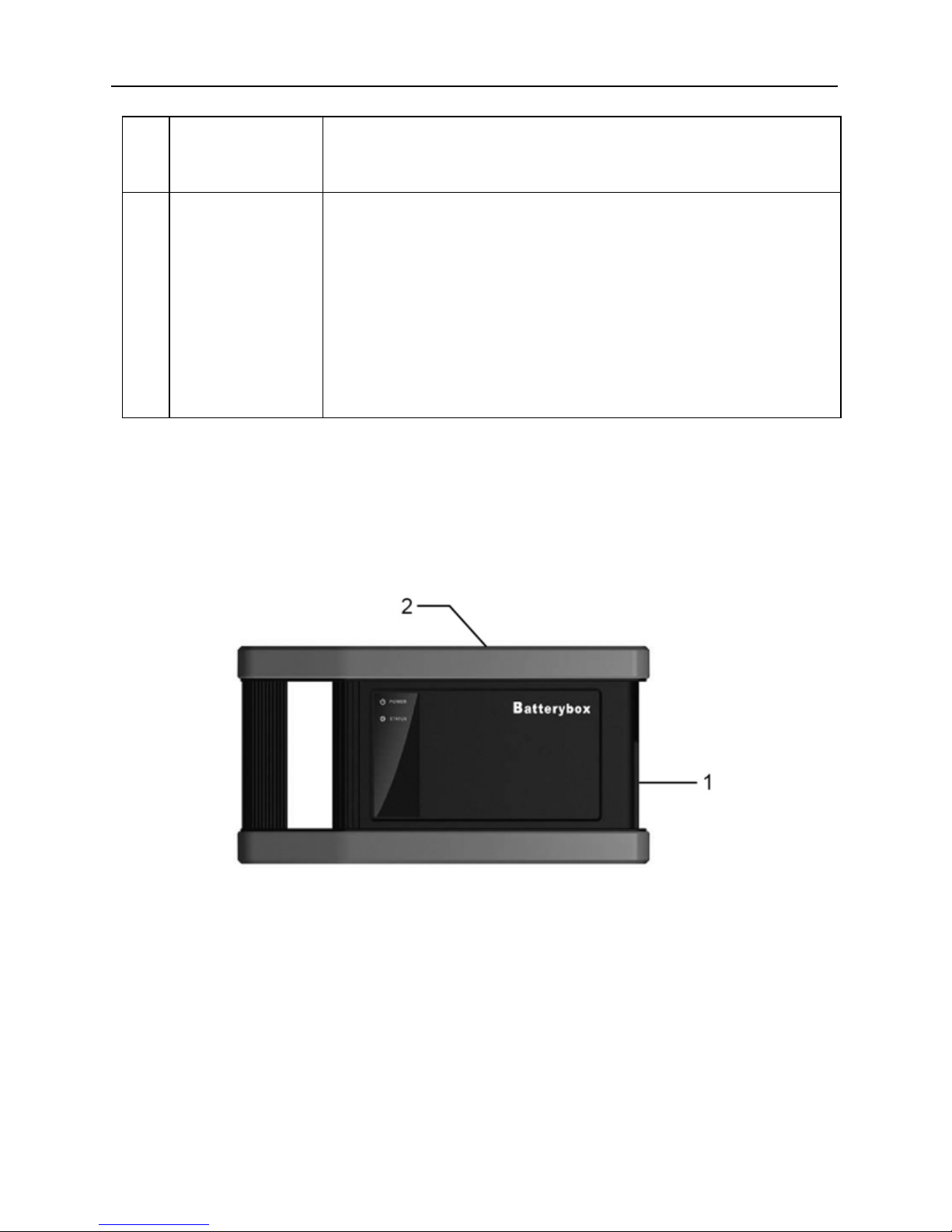
2.3.1 Batterybox structure
Fig.2-1 Batterybox structure diagram
1. Battery connector: Connect to battery for battery test.
2. B type USB terminal: Connect to the GDS main unit with a USB cable.
4
Page 7

LAUNCH X-431 GDS Batterybox Manual
2.3.2 Test accessories
Fig. 2-2 Kelvin clip
Fig. 2-3 A/B cable
5
Page 8

LAUNCH X-431 GDS Batterybox Manual
3. Connections & Operations
3.1 Connection
Connect one end of the A/B cable to the B type USB terminal of the batterybox,
and then connect the other end to the USB port of GDS main unit. This
connection applies to outside the vehicle test and inside the vehicle.
Notes:
1. Wait about 10s and begin to communicate since the batterybox needs to
initialize after connection is complete, otherwise, communication may fail.
2. Red lamp on the batterybox means it has been successfully powered up; If
the green light is always on, it indicates the clip is well connected; while the
green light blinks, it indicates that the clip has poor contact. Do not perform
any test until the clip and A/B cable are properly connected.
3.2 Inside the vehicle test
Battery test and charging system & actuation system test can be done in this
mode.
3.2.1 Battery test
1. Enter battery test main menu, and select a desired test environment as
shown in Fig. 3-1.
6
Page 9

LAUNCH X-431 GDS Batterybox Manual
Fig. 3-1
Button Descriptions:
[System]: 3 submenus are available: Show desktop (return to desktop),
Version (view the current version info) and Exit program (exit the
current program).
[Help]: views introduction and operation guideline for battery test.
[Next]: proceed to the next operation.
[Reset]: stop all current operation and enter initializing interface.
Note: The sequences of inside the vehicle and outside the vehicle test are
almost the same, but under inside the vehicle condition, all loads in vehicles
must be powered off for getting an exact test value.
2. Firstly, detect whether floating electricity exists or not before testing. If yes,
turn on the headlamp to remove it. Otherwise, the system starts test
program directly.
7
Page 10

LAUNCH X-431 GDS Batterybox Manual
Select [Battery testing] > [Inside the vehicle], then click [Next], the system
starts detecting floating electricity automatically. A screen similar to Fig. 3-2
appears if floating electricity is detected.
3. Follow the
on-s
will be shown as below.
Fig. 3-2
creen instructions to turn on headlamp, then the interface
Fig. 3-3
8
Page 11

LAUNCH X-431 GDS Batterybox Manual
4. Once the floating electricity is removed, a prompt message box will appear
on the screen.
Fig.3-4
5. Follow the on-screen instructions to turn off the headlamp and click [OK],
the system will continue the testing. Click [Next], it will go into Selecting
testing standard screen. See Fig. 3-5
Fig. 3-5
9
Page 12

LAUNCH X-431 GDS Batterybox Manual
6. Select a testing standard except for JIS and click [Next], a screen similar
to Fig. 3-6 will appear. Users can adjust capacity size by tapping on << or
>> or by dragging the slider on the bar.
Fig. 3-6
If JIS is sel
ected, click [Next], the system will enter Select testing capacity
screen. Users can select corresponding standard capacity value according
to battery model marked on battery.
Fig. 3-7
10
Page 13

LAUNCH X-431 GDS Batterybox Manual
7. Click [Next] and the testing result will appear on the following screen.
Fig. 3-8
3.2.2 Charging system and starting system test
While performing this test, the battery’s charging voltage value and starting
voltage can be obtained in case of engine starting and accelerating. Based on
the data, the system will judge whether battery’s charging and actuation status
is normal or not.
1. The interface will display as Fig. 3-9 after the engine starts.
11
Page 14

LAUNCH X-431 GDS Batterybox Manual
Fig. 3-9
ectin
2. After det
g engine starting, follow the instructions on the screen to
increase the speed.
Fig. 3-10
3. The sys
tem begins to receive test data information after acceleration was
detected, as shown in Fig. 3-11.
12
Page 15

LAUNCH X-431 GDS Batterybox Manual
Fig. 3-11
4. Tested data will be shown on the screen, similar to Fig. 3-12.
Note: It is unnecessary to perform charging system and start system test after
finishing battery test, but battery test must be done before undergoing
charging system and starting system test.
Fig. 3-12
13
Page 16

LAUNCH X-431 GDS Batterybox Manual
3.4 Outside the vehicle test
It only applies to battery test and detecting floating electricity will be ignored
while performing battery test.
1. On Fig. 3-1, select [Outside the vehicle], and click [Next] to enter.
Fig.3-13
2. Select a
testing standard except for JIS and click [Next], the system will
enter a screen shown as Fig. 3-14. The capacity value can be adjusted by
touching << or >> or by dragging the slider on the bar.
Fig. 3-14
14
Page 17

LAUNCH X-431 GDS Batterybox Manual
If JIS is selected, click [Next], it will enter Select testing capacity screen.
Users can select corresponding standard capacity value according to
battery model marked on the battery.
3. Click [
Fig. 3-15
Next] and the testing results will appear on the following screen.
Fig. 3-16
15
Page 18

LAUNCH X-431 GDS Batterybox Manual
Button Descriptions:
[System]: 3 submenus are available: Show desktop (return to desktop),
Version (View the current version info) and Exit program (exit the
current program).
[Help]: views introduction and operation guideline for battery test.
[Print]: print test results.
[Retry]: display test results again.
[Reset]: stop all current operation and enter initializing interface.
Note: All buttons are invalid unless the print was completed.
3.5 Review version info
1. In Fig. 3-1, click [system], a pull-down menu will pop up.
Fig. 3-17
16
Page 19

LAUNCH X-431 GDS Batterybox Manual
2. Click [version], a message box will be shown on the following screen.
Fig. 3-18
17
Page 20

LAUNCH X-431 GDS Batterybox Manual
4. Precaution items on battery test
1. For the purpose of getting accurate test results, unless otherwise special
required, all loads need to be power off such as headlamp, engine etc.
before testing battery.
2. The operating time required for charging system and actuation system
test varies from person to person. If the engine does not start or
accelerate within 30 seconds, the system will prompt you “receiving
timeout” and return to the initial status.
3. Whether Engine is off or not has no influence on charging and actuation
test result after increased speed is detected, but other loads need to be
powered off.
4. The accuracy of battery voltage, charging voltage, start voltage is 0.01V in
test results; CCA (Cold Cranking Amps) precision is 5CCA.
5. Generally, charging voltage value is greater than starting voltage.
Charging voltage range is as follows: 13.8--14.5V for domestic vehicle;
13.3--15.5V for imported vehicles. The voltage varies with different car
models, so you have to judge based on related vehicle models. In general,
the DC voltage is stable, but it also varies with different revolution speed.
Starting voltage range: the value higher than 9.6V is regular, otherwise it
is too low. Due to different situations, whether the starting voltage is
higher or not does not mean the vehicles or batteries are faulty. For
detailed faults, other special equipments are needed. To validate the
accuracy of the value, the best method is to collect the signals of starting
and charging voltage and observe it on an oscillometer.
6. Generally, the voltage is lower than 11V for the bad cell battery, but it is
possible that the battery is completely exhausted or has a serious low
18
Page 21

LAUNCH X-431 GDS Batterybox Manual
capacity. In this case, just recharge your battery. Bad cell always happens
when the loads on a stopping vehicle are turned on for a long time.
7. Please note that it is normal for quick detecting of “Increase speed”
because it follows the theory of detecting “Increase speed”: if the detected
voltage is higher than the previous battery test voltage, the system will
prompt you a message of “Engine has been speeded”
8. It has no influence on test result in the event that engine’s output voltage
or engine revolution is not very stable. No matter whether the vehicle is
accelerated or not, the output voltage only differs within 0.2V.
9. While doing inside the vehicle test, Kelvin clip is always found to be in
poor contact. To remain it in good contact, please shake it several times
before testing. Take down the battery connector, and test it again, the
value probably varies. The deviation may arise from battery connector.
10. Pay more attention to connect the clip. The battery poles connect with
conductor, which makes the clip has a poor connection when testing
battery. A tolerance of dozens of CCA occurs if the clip is out of position,
or oil, dust attaches on the pole. The gear and main body of clip should be
fully matched with battery poles.
Notes:
1. Battery poles inside the vehicle are enveloped by connectors, which may
produce some errors for test results. The tolerance results from the
resistance of connectors. The greater the resistance value is, the greater
the tolerance becomes. But generally, the tolerance does not affect the
test conclusion.
2. Testing the battery separately generates an exact test result. The battery
box is a very useful auxiliary tool for quick test. If any problems were
found, test it separately for getting an exact test result.
19
 Loading...