

Page 1

LAUNCH X-431 User’s Manual
to the purchaser of this unit or third parties for
Trademark Information
LAUNCH is a registered trademark of
LAUNCH TECH. CO., LTD. (short for LAUNCH )
in China and other countries. All other LAUNCH
trademarks, service marks, domain names,
logos, and company names referred to in this
manual are either trademarks, registered
trademarks, service marks, domain names,
logos, company names of or are otherwise the
property of LAUNCH or its affiliates. In
countries where any of the LAUNCH
trademarks, service marks, domain names,
logos and company names are not registered,
LAUNCH claims other rights associated with
unregistered trademarks, service marks,
domain names, logos, and company names.
Other products or company names referred to
in this manual may be trademarks of their
respective owners. You may not use any
trademark, service mark, domain name, logo, or
company name of LAUNCH or any third party
without permission from the owner of the
applicable trademark, service mark, domain
name, logo, or company name. You may
contact LAUNCH by visiting Launch at http://
www. cnlaunch. com, or writing to LAUNCH,
Xinyang Building, Bagua 4th Road, Shenzhen,
Guangdong Province, P. R. C., to request
written permission to use Materials on this
manual for purposes or for all other questions
relating to this manual.
Copyright Information
Copyright © 2000 by LAUNCH TECH. CO., LTD.
All rights reserved. No part of this publication
may be reproduced, stored in a retrieval system,
or transmitted in any form or by any means,
electronic, mechanical, photocopying, recording
or otherwise, without the prior written
permission of LAUNCH. The information
contained herein is designed only for the use of
this unit. LAUNCH is not responsible for any
use of this information as applied to other units.
Neither LAUNCH nor its affiliates shall be liable
damages, losses, costs, or expenses incurred
by purchaser or third parties as a result of:
accident, misuse, or abuse of this unit, or
unauthorized modifications, repairs, or
alterations to this unit, or failure to strictly
comply with LAUNCH operating and
maintenance instructions.
LAUNCH shall not be liable for any damages or
problems arising from the use of any options or
any consumable products other than those
designated as Original LAUNCH Products or
LAUNCH Approved Products by LAUNCH.
General Notice
l Other product names used herein are for
identification purposes only and may be
trademarks of their respective owners.
LAUNCH disclaims any and all rights in
those marks.
l There is a possibility that this unit is
inapplicable to some of the vehicle models
or systems listed in the diagnosis section
due to different countries, areas, and/or
years. Do not hesitate to contact LAUNCH
if you come across such questions. We are
to help you solve the problem as soon as
possible.
Disclaimer
l To take full advantage of the unit, you
should be familiar with the engine.
l All information, illustrations, and
specifications contained in this manual are
based on the latest information available at
the time of publication. The right is
reserved to make change at any time
without notice.
i
Page 2

LAUNCH X-431 User’s Manual
Table of Contents
Introduction...........................................................1
Features...........................................................1
Convenient to Update..................................1
Advanced.....................................................1
Open............................................................1
Integrative....................................................1
Flexible........................................................1
Precaution on Operation..................................1
Maintenance.....................................................2
Storage........................................................2
Take Care of the Screen..............................2
Maintenance of CF card..............................2
Consumption Material..................................3
Outline of X-431...............................................3
Function of the Three Main Parts.....................3
X-431 Main Unit...........................................3
SMARTBOX.................................................3
MINIPRINTER.............................................4
Specifications...................................................4
Hardware Configuration...................................4
Layout of Three Main Parts..............................5
Working Principle of X-431...............................5
Block Diagram of X-431 Hardware...................6
Working Procedure of X-431.......................6
Ports and Indicators.........................................6
Printer Operation..............................................7
Mounting Paper...........................................7
Printing Test Result......................................8
Explanation of Buttons.....................................8
Vehicle Diagnosis.................................................9
Button Descriptions..........................................9
Conditions for Test...........................................9
Select Diagnostic connector.............................9
Diagnostic Socket Location..............................9
Pin Definitions..................................................9
Connection.....................................................10
Operation.......................................................10
Entering Function Menu.............................10
Read ECU Memory....................................13
Read Fault Memory....................................13
Erase Fault Memory...................................14
Diagnose Final Control...............................15
Basic Setting..............................................15
Read Measuring Value...............................16
Read Individual Measuring Value...............17
Adaptation..................................................17
Code Control Unit.......................................18
End Output.................................................19
Login Procedure.........................................19
Update of Diagnostic Software...........................21
Hardware Requirement..................................21
User Registration............................................21
Read Terms of Service...............................21
Fill in Necessary Information......................22
Member Login.................................................22
Member Area..................................................23
Account Administration...............................23
Product Control..........................................23
User’s Information Maintenance................23
Order Information.......................................23
Logout........................................................23
Software Download........................................23
Software Update.............................................25
Flow Chart of X-431 Update for New User.....27
Main Unit.............................................................28
Introduction.....................................................28
Interface.....................................................28
Input................................................................30
Using the Soft Keyboard............................30
Input by Keyboard......................................30
Input by Writing Board................................30
Control of App.................................................31
Check Box..................................................31
Scrolling Bar...............................................31
Common Button.........................................31
Help............................................................31
ii
Page 3

LAUNCH X-431 User’s Manual
Tool and Game...............................................32
Tools..........................................................32
Game.........................................................34
PIM.................................................................35
Memo.........................................................35
Delete Address..........................................38
Search Address.........................................38
To Do.........................................................39
Schedule....................................................41
System...........................................................43
Control Panel.............................................43
System Information....................................47
Shut Down.................................................48
FAQ....................................................................49
About Update via Internet..............................49
About Hardware.............................................50
About System Setting.....................................51
About Operation.............................................52
Questions Related to Vehicle.........................53
About ECU..........................................................54
Composition and Working Principle of
Computer- Control System.............................54
Sensor.......................................................54
ECU...........................................................55
Actuator.....................................................55
Self-diagnosis of Electronic Control System..56
Working Principle of Self-diagnosis...........56
Readout of Fault Code in Automotive
Self-diagnosis System...............................56
Basic Knowledge of ECU...............................57
Composition of Vehicle ECU......................57
Precautions Related to ECU......................57
Appendix 1: about VIN........................................59
Appendix II: Block and Parameter Definition of
Volkswagen Vehicle............................................61
Passat B5 Engine Data Stream Block Table..61
Passat B5 AT System Data Stream Block Table
.......................................................................65
Passat B5 ABS Data Stream Block Table......66
Jetta Engine System Data Stream Block Table
........................................................................67
Golf Engine System Data Stream Block Table70
Audi 200 Engine System Data Stream Block
Table...............................................................71
Appendix III: Channel Function Table of
Volkswagen Vehicle............................................73
Audi 200.........................................................73
Audi A6...........................................................73
Passat B5.......................................................73
Appendix IV: Control Unit Code of Popular
Volkswagen Vehicles..........................................74
Audi A6...........................................................74
Passat B5.......................................................78
Jetta................................................................79
iii
Page 4

LAUNCH X-431 User’s Manual
Integrative
Introduction
X-431 is a newly developed automobile
diagnostic computer. It is based on the
technology of open diagnostic platform, the
most advanced automobile diagnostic
technology brought forward by LAUNCH.
The open diagnostic platform represents the
highest level of automobile diagnostic
technology, and is the developing trend of this
field in the future.
Features
Convenient to Update
l The function of software update via Internet
makes it easy for customer to get the latest
diagnostic program and keep pace with the
development of automotive technology.
l Multilanguage display makes operation
convenient in different countries and areas.
Advanced
X-431 is the most advanced automobile
diagnostic unit in the world at present. It is
compactly designed and with large LCD touch
screen. Demountable printer makes the
operation easy.
The product is a combination of the automobile
industry and the communication technology,
which starts the new development trend in the
automobile diagnosis field. This product not
only provides a new way of automotive
diagnosis for vehicle service station, but also
becomes a favorable choice for “DIYers”.
X-431 has all functions of PDA.
Handwriting input, personal database, vast
vocabulary English-Chinese dictionary. The
super capacity database can realize
multi-purpose management of user’s
information.
Flexible
X-431 has a fire-new modern design. Each
function can be combined with others at will or
used independently.
l The main unit and the diagnostic box can
be used independently.
l The main unit itself is equal to a PDA,
which has the functions of personal
database, etc.
l The SMARTBOX can be connected to PC
to perform automobile diagnosis when it is
demounted from the main unit. The
diagnostic software used by PC can even
be downloaded on the LAUNCH website.
That is, the SMARTBOX can be sold
independently. This is the important feature
of X-431.
l A standard RS232 interface is used to
connect the SMARTBOX and its upper unit.
So more BOXes can be designed to
increase functions, such as SENSORBOX,
REMOTEBOX, etc. This feature increases
the value of X-431.
l MINIPRINTER is detachable. User can use
it to print out data.
As described above, the independent use of the
main unit and the SMARTBOX (or other
diagnostic box) is the extraordinary and creative
feature of X-431.
Open
l Open operating system. That is, X-431 is
an open automobile diagnostic platform
with multifunction and multi-language
based on LINUX operating system.
l X-431 provides open interface to support
the third party’s development.
Precaution on Operation
l The X-431 is equipped with a leather
cover for protecting the machine and
firmly combining the main unit,
SMARTBOX and MINIPRINTER together.
Do not remove the leather cover during
operation. Try your best to keep the
screen facing upward and leveled.
1
Page 5

LAUNCH X-431 User’s Manual
l Be careful when plugging and unplugging
the main cable and diagnostic connector.
Tighten the screw before operation so as
to avoid unexpected disconnecting and/or
damage to the port.
l Hold the X-431 main unit during operation.
Do not hold the SMARTBOX or
MINIPRINTER so as to prevent the
SMARTBOX and MINIPRINTER from
being disconnected.
l Firmly hold the main unit when connecting
or disconnecting MINIPRINTER or
SMARTBOX to avoid dropping down.
l Do not insert and pull out CF card too
frequently. Press ejector button before
pulling out the CF card. Insert the CF card
into the CF card slot, keep the face
labeled “UPSIDE” upward, and make
sure the card is fully seated.
l Handle with care. Avoid hitting. Unplug the
power after operation.
l Put the stylus into the hole at back of
X-431 main unit after operation. And put
the cables, connectors and other
accessories into box.
l When it is necessary to remove the
leather cover, pull out the CF card first and
push in the ejector button to avoid
scratching the leather cover.
l Hold the connector when plug or unplug it.
Do not pull the cable for unplugging.
Maintenance
Storage
l Store the X-431 on a flat and dry place
with suitable temperature.
l Never put the X-431 in direct sunlight or
near the heating source.
l Prevent smoke, water and oil from
entering the X-431.
l Avoid shock, dust, moisture and extremely
high temperature.
l Do not disassemble the main unit. Clean
the outside surface and screen with soft
cloth that is dipped with a little water if the
main unit is dirty. This should be done
after the machine is turned off and the
power cable is removed.
l Periodically turn on the X-431 main unit if
it is not operated for long time to avoid
moisture.
Take Care of the Screen
l Turn off the power if it is expected not to
operate the X-431 for a long while. It can
extend the life of screen and save energy.
l Do not put anything on the main unit to
avoid damage to the internal parts.
l Use the equipped stylus to click the
screen. Do not use fingernail or other
sharp object to touch the screen.
l Dust may be accumulated on the LCD
screen owing to electrostatic. It is
suggested to buy the special LCD screen
wiper to clean the screen gently. Do not
wipe the screen with bare finger.
l Never use chemicals to clean the screen.
Maintenance of CF card
l Do not pull out the CF card when the
X-431 main unit is working.
l Pull out the CF card and store it in the
place without magnetic field after the
machine is turned off. Do not turn on/off
the X-431 main unit too frequently.
l CF card reader/writer may be used when
doing updating. The CF card must not be
pulled out when the CF card reader/writer
is being used. Otherwise, the data in the
CF card will be lost. Procedure for pulling
2
Page 6

LAUNCH X-431 User’s Manual
out the CF card is as follows:
On the desktop of Windows, open the
window of “My computer”. Click the right
mouse button on “Removable disk” to pop
up a menu. Select “Ejector (J)” in the
menu. Then pull out the CF card. The
written data may be lost if the CF card is
pulled out discretionarily. When you want
to use the CF card again, put it in.
l In case X-431 CF card is damaged and
the program in the card can not be used,
please use the following procedure to
remake the CF card:
² Log onto the website
"www.X431.com". Enter your
username and password to log in.
Select the SMARTBOX No., and
then download the X-431 UPDATE
TOOLS, DISPLAY PROGRAM,
SYSTEM DATA and necessary
diagnostic program into your
computer.
² Install the X-431 UPDATE TOOLS
into computer.
² Format the X-431 CF card.
² Run the X-431 UPDATE TOOLS and
write the display program, system
data and diagnostic programs onto
CF card.
Consumption Material
Printing paper.
Refer to the section “Printer Operation” for
paper installation.
Outline of X-431
Figure 1-01
Figure 1-01 shows the main parts of X-431.
They are: X-431 main unit, SMARTBOX and
MINIPRINTER. Each of the three parts has
independent function. They may work
separately or be connected together according
to different requirement of configuration.
For easy operation, the three parts are usually
connected together and enclosed in a leather
cover for preventing looseness or damage.
Additional parts, such as main cable, power
cable, power adapter, CF card, CF card
reader/writer, diagnostic connectors and so on,
are equipped for vehicle diagnosis.
Function of the Three Main
Parts
X-431 Main Unit
The X-431 main unit is like a PDA when it is
used independently. It has all functions of a
standard PDA, including personal information
management, control panel, game, etc.
SMARTBOX
SMARTBOX is the main part for vehicle
diagnosis. It can be connected to PC for vehicle
diagnosis if the X-431 main unit is not
connected. So the SMARTBOX can be sold
independently and be used with PC that has
3
Page 7
LAUNCH X-431 User’s Manual
relevant software. The software is available on
our website at http:// www. X431. com. This is
an important feature of the product.
SMARTBOX is designed elaborately for future
update.
The interface for connecting SMARTBOX and
its upper unit is RS232. More BOXes can be
developed to increase the function of the
product, such as SENSORBOX, REMOTEBOX,
etc. It makes the product more and more
valuable.
MINIPRINTER
It is connected with X-431 main unit via a
standard parallel port for printing out the test
result. Thermal printer paper (size: Φ30×57mm,
bore diameter:Φ7mm) is used.
Specifications
l Operating system: LINUX
l RAM: 16M
l CF card: 64M
l Main unit I/O: standard serial/parallel port
l Main unit power source: DC12V
l Main unit power: about 9W
l Printer: high-speed thermal mini printer
l Printer port: standard parallel port
l Screen: 240*320 LCD touch screen with
back light
l Configuration: Main unit, Smartbox and
miniprinter
Hardware Configuration
For vehicle diagnosis, some accessories (e.g.
connectors and cables) should be used to
connect the X-431 main parts to the vehicle
diagnostic socket.
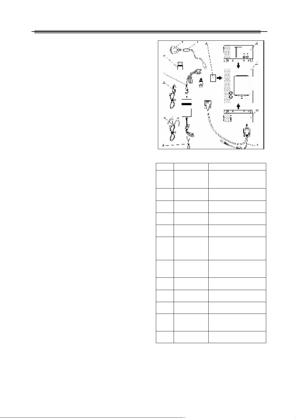
X-431 configuration is as shown in Figure 1-02.
Item
X-431 main
1
unit
2 MINIPRINTER
3 CF card
4 USB cable
CF card
5
reader/writer
Diagnostic
6
connector
7 Power cord
Cigarette
8
lighter cable
Battery cable
9
w/two clips
10 Power adapter
11 Main cable
12 SMARTBOX
Figure 1-02
Name Descriptions
To display operation
buttons, test result, help
information, etc.
To print test result.
(optional)
To store diagnostic
software and data
To connect CF card
reader/writer and computer
To read or write data on
the CF card
Dozens of connectors are
equipped for various
vehicles. Here shows a
typical one.
To connect the AC
100-240V (50-60Hz) outlet
and the power adapter.
To get power from the
vehicle cigarette lighter
To get power from the
vehicle battery
To convert 100-240V AC
power into 12V DC power.
To connect the diagnostic
connector and
SMARTBOX
To perform vehicle
diagnosis
4
Page 8
LAUNCH X-431 User’s Manual
Paper
Out
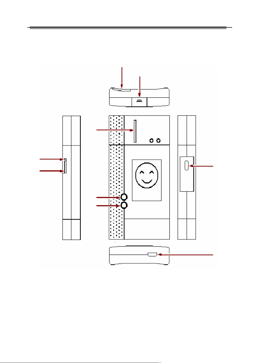
Layout of Three Main Parts
Paper In
Printer adjustor
Ejector
Serial Port 1
CF Card Slot
Hot Key
Power Button
Working Principle of X-431
X-431 combines the technology of automobile
and computer. It uses computer technology to
scan the trouble code in various systems of
automobile. The test result is displayed on the
LCD screen in forms of characters, digits,
waveforms, etc, or is printed out. User can
Touch Screen
DATA I/O
Figure 1-03
know the trouble type, cause, location and
troubleshooting solutions on vehicle according
to the displayed information. X-431 can also
clear the trouble code after vehicle is repaired.
X-431 is based on Linux operating system and
adopts SMARTBOX for vehicle diagnosis. It can
diagnose vehicles made by different
manufacturers. The test can be automatized
5
Page 9
LAUNCH X-431 User’s Manual
and computerized.
X-431 features high automation, powerful
function, large database, multi-language,
compact structure and easy operation.
All advantages are realized by the following
techniques:
l Advanced main unit circuit. It includes
CPU, LCD, keypad, EPROM,
re-programmable data memory, universal
interface, some supplementary circuits.
l Various diagnostic circuits. One end is
connected to the main unit and the other
is to vehicle diagnostic socket for
diagnosing different vehicle model.
l Specific diagnostic program for specific
vehicle.
l Splendid programming. Programs, font
database and information are loaded from
PC to X-431 via communication.
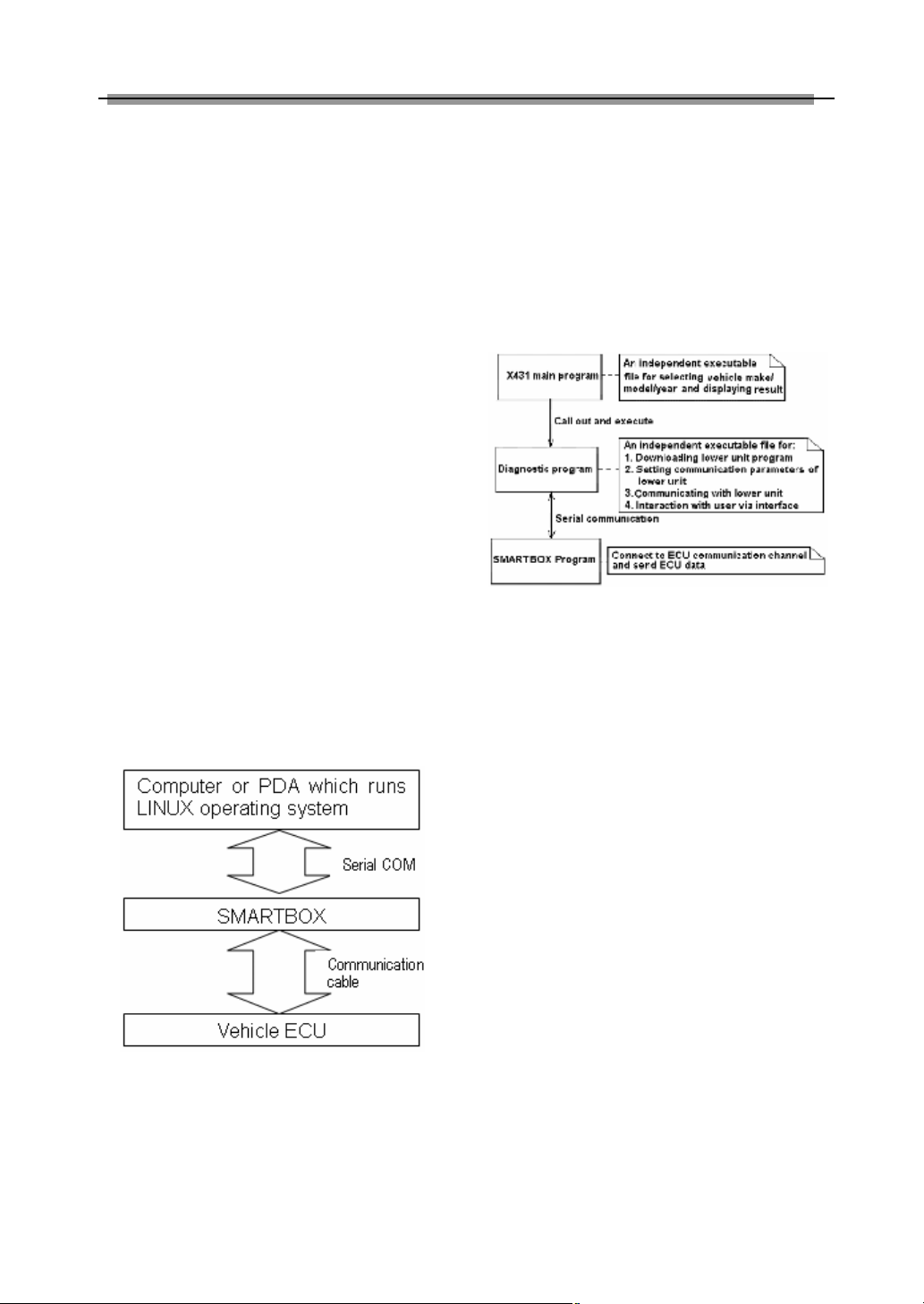
Block Diagram of X-431
Hardware
As shown in Figure 1-04. The upper unit is a
computer with Linux operating system which
can run diagnostic program. The lower unit is
SMARTBOX which matches the voltage,
baudrate and other signal logic. The upper unit
and lower unit are connected via serial port.
The SMARTBOX is connected to vehicle ECU
through cable and connectors.
Working Procedure of X-431
Figure 1-05
Figure 1-05 shows the working procedure of
X-431. In the “X-431 main program”, after user
select vehicle make and diagnostic program,
“X-431 main program” downloads the
SMARTBOX program for the vehicle to the
SMARTBOX and makes the SMARTBOX run
the program; then creates the diagnostic
procedure and calls out the “Diagnostic
program” so that the “Diagnostic program” and
the SMARTBOX program perform the whole
process of diagnosis. “X-431 main program” is
to display the diagnostic result and interact with
user.
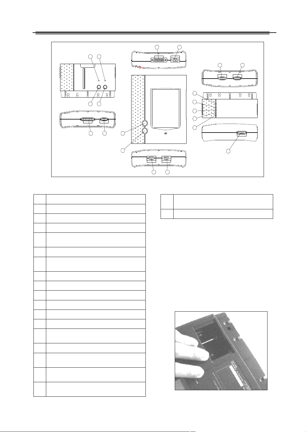
Ports and Indicators
See Figure 1-06 for X-431 connection ports and
indicators
Figure 1-04
6
Page 10
LAUNCH X-431 User’s Manual
2
4
78
21
13
15
43
65
9
16
17
18
19
14
10
Printer SEL indicator(printer readiness)
1
Printer power indicator
Printer SEL button(printer readiness)
3
Printer FL button(paper feed)
Parallel communication port for
5
connecting printer to main unit
Power input for printer
6
Parallel communication port for
7
connecting main unit to printer
Power output of main unit.
8
Hotkey of main unit
9
Power switch of the main unit.
10
11 Power input of main unit
12 Serial communication port of main unit
13 Power output of SMARTBOX
Serial communication port of
14
SMARTBOX
15 SMARTBOX power indicator
Indicator to show SMARTBOX sending
16
data to the main unit
Indicator to show SMARTBOX receiving
17
data from the main unit
Indicator to show SMARTBOX sending
18
data to ECU
1112
Figure 1-06
Indicator to show SMARTBOX receiving
19
data from ECU
20 SMARTBOX data port
Printer Operation
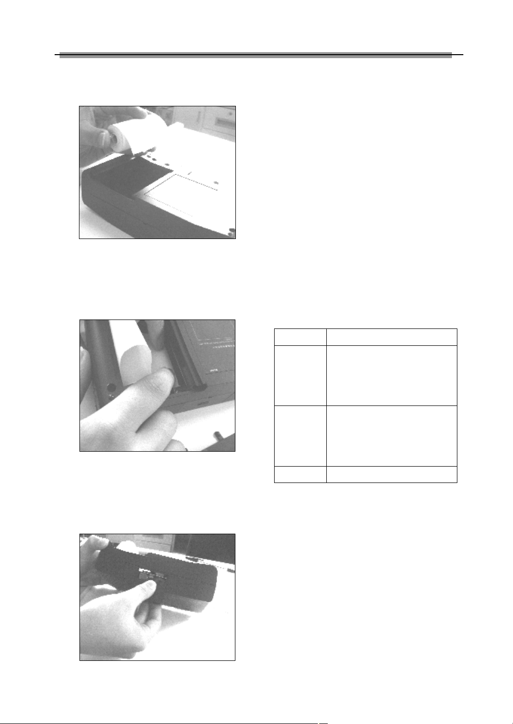
Mounting Paper
MINIPRINTER uses heat sensitive paper with
size of Φ30×57mm (internal holeΦ7mm).
Refer to Figure 1-07a to Figure 1-07d for
mounting the paper.
1. Open the paper lid on the back of the
printer. See Figure 1-07a.
20
Figure 1-07a
7
Page 11
LAUNCH X-431 User’s Manual
2. Take out the spindle and mount the paper
scroll onto the spindle. See Figure 1-07b.
Figure 1-07b
3. Put the paper spindle into the printer with
correct direction. The paper may not be fed
if the direction is wrong. See Figure 1-07b
and Figure 1-07c.
Figure 1-07c
4. Open the side plate, pull up the pressing
rod and lead the paper into slot. Turn the
feed knob clockwise until the paper comes
out of the outlet. See Figure 1-07d.
5. Push down the pressing rod, mount the
side plate, attach the paper lid, and then
connect the printer to the X-431 main unit.
Printing Test Result
There are two indicators on the printer:
1. [SEL]:to show the readiness of the printer.
2. [POWER]: the power indicator of the
printer.
If the [SEL] indicator is not lit, you can press the
[SEL] button to turn it on and make the printer
ready.
When the [SEL] indicator is lit, it shows that the
printer is ready. Click the [PRINT] button (if it
appears) on the screen of X-431 main unit to
print the test result.
Explanation of Buttons
[POWER]
[HOTKEY]
[SEL]
[FL] Paper-feed button.
Power button
Hot key. Press it to calibrate
the screen after the machine is
turned on. Or press it to enter
the vehicle diagnosis interface
after X-431 is started.
To select the printer. When
[SEL] indicator is lit, the printer
is ready to print. If [SEL]
indicator is not lit, the printer is
not able to print.
Figure 1-07d
8
Page 12
LAUNCH X-431 User’s Manual
described procedure and the screen
Vehicle Diagnosis
Button Descriptions
The main buttons on the operation interface
and their functions are as follows:
[BACK]: to return to the previous interface.
[START]: to do the next operation.
[EXIT]: to exit the diagnostic program.
[OK]: to confirm and execute.
[CANCEL]: to cancel present operation and
return to the previous interface.
[PAGE UP]: to display the previous page. It is
inactive if the current page is the first page.
[PAGE DOWN]: to display the next page. It is
inactive if the current page is the last page.
[HOME]: return to the main interface.
[PRINT]: to print the test result.
[BOX INFO]: to show the version information
of SMARTBOX.
[HELP]: to display the help information.
[RETRY]: to do the unfinished operation once
again.
prompts when diagnosing other vehicle.
Volkswagen vehicle is usually equipped with
4PIN or 16PIN diagnostic socket.
Please select the [Audi-4] diagnostic
connector for 4PIN diagnostic socket or [Smart
OBDII] diagnostic connector for 16PIN
diagnostic socket.
Diagnostic Socket Location
The diagnostic socket of Volkswagen vehicle
is located in the cab under the instrument at
the driver side.
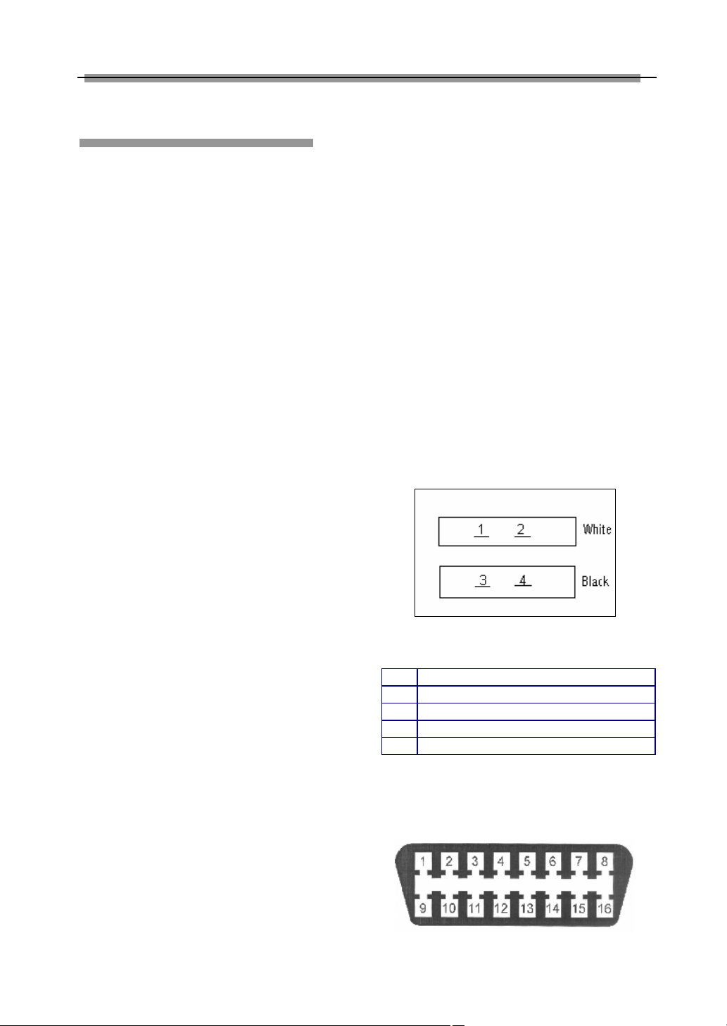
Pin Definitions
4PIN Diagnostic Socket
The 4PIN diagnostic socket is as shown in Figure
2-01.
Conditions for Test
l Turn on the key.
l The voltage of vehicle battery should be
11-14V. The rated voltage of the X-431 is
12V.
l The throttle should be in the closed
position.
l X-431 can be operated in the temperature
of 0-50℃. (30 minutes of warming-up
may be necessary when the ambient
temperature is 5℃) .
Select Diagnostic connector
Various diagnostic connectors are supplied
with X-431. Select a specific connector
according to the tested vehicle.
Let’s take Volkswagen vehicle as example to
describe the test procedure.
Note:
The test procedure for different vehicle
make is similar. Please refer to the
Figure 2-01
PIN definition of 4PIN diagnostic socket
PIN
1 L line
2 K line
3 Grounding
4 Power
16PIN Diagnostic Socket
The 16PIN diagnostic socket is as shown in Figure
2-02.
Definition
Figure 2-02
9
Page 13
LAUNCH X-431 User’s Manual
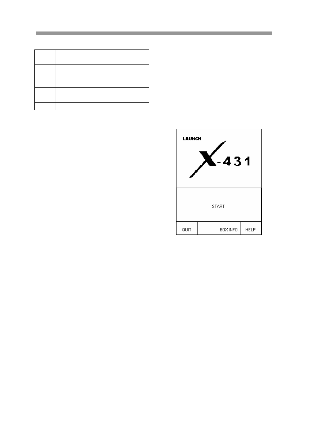
PIN definition of 16PIN diagnostic socket
PIN
2 BUS+
4 Grounding
5 Grounding
7 K line
10 BUS15 L line
16 Power +12V
Definition
Connection
l Insert the CF card into the CF card slot,
keep the face labeled “UPSIDE”
upward, and make sure the card is fully
seated.
l Insert one end of the main cable into the
diagnostic socket on SMARTBOX.
l Connect the other end of the main cable
to the diagnostic connector.
l Connect the other end of the diagnostic
connector to the vehicle diagnostic
socket.
Note:
If the power supply on vehicle diagnostic
socket is insufficient or the power pin is
damaged, you can get power in the
following ways:
♦ From cigarette lighter: insert one end
of the cigarette lighter cable into the
lighter socket in vehicle and connect
the other end to the power connector of
X-431 main cable.
♦ From battery: clamp the two clips of
battery cable on the positive and
negative poles of battery and insert
another end of the cable into the power
connector of X-431 main cable.
♦ From power adapter: connect the
power adapter to the 100-240V AC
outlet with power cord. Insert the 12V
DC plug of power adapter into the
power connector of X-431 main cable
Operation
Entering Function Menu
After connection, press [POWER] key to start
X-431.
After starting the main unit, press [HOTKEY]
(or click [Start] button on the main menu, and
select [GAG]→ [GD Scan] on the pop-up
menu), the screen will display the home page
of vehicle diagnosis as shown in Figure 2-03.
Figure 2-03
Button descriptions:
♦ [QUIT]: to exit the diagnostic program.
♦ [BOX INFO.]: to display hardware and
software version of SMARTBOX.
♦ [HELP]: to display help information.
♦ [START]: to start the diagnosis.
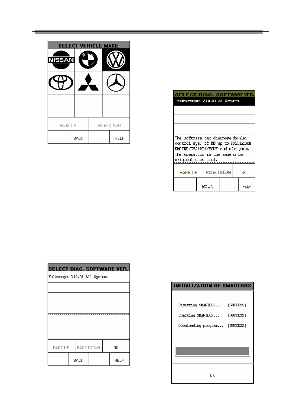
Click [START] button, the screen will display
the vehicle make menu as shown in Figure
2-04.
10
Page 14
LAUNCH X-431 User’s Manual
♦ [BACK]: to return to the previous
interface.
♦ [HELP]: to display the help information.
Click [Volkswagen V10.01 All Systems]. The
display will be as shown in Figure 2-06.
Figure 2-04
Button descriptions:
♦ [BACK]: to return to the previous
interface.
♦ [PAGE UP]: to display the previous
page, it is inactive if the current page is
the first page.
♦ [PAGE DOWN]: to display the next page,
it is inactive if the current page is the
last page.
♦ [HELP]: to display the help information.
Click the icon of Volkswagen on the vehicle
make menu. The screen will be displayed as
shown in Figure 2-05.
Figure 2-06
The software can diagnose the electronic
control systems of Volkswagen up to 2002.
The operation is the same as that of the
original scan tool.
Click [OK] button, X-431 begins reset and
check the SMARTBOX, and download the
diagnostic program from the CF cartridge.
After download, the screen will be displayed
as shown in Figure 2-07.
Figure 2-05
Button descriptions:
Figure 2-07
11
Page 15
LAUNCH X-431 User’s Manual
Button descriptions:
[OK]: to go on the test.
Click [OK] button, the screen will display the
information as shown in Figure 2-08.
Figure 2-08
Button descriptions:
♦ [HOME]: to return to the homepage of
vehicle diagnosis.
♦ [BACK]: to return to the previous
interface.
♦ [HELP]: to display the help information.
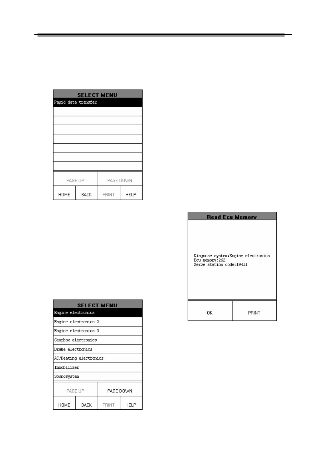
Click [Rapid Data Transfer]. The screen
displays the menu of test systems as shown in
Figure 2-09.
There are several pages for the menu. Click
[PAGE DOWN] to see the next page.
Note:
The test operation for different systems is
similar. Here we take [Engine electronics]
as an example to describe.
Button descriptions:
♦ [PAGE DOWN]: to display the next
page.
♦ [HOME]: to return to the homepage of
vehicle diagnosis.
♦ [BACK]: to return to the previous
interface.
♦ [HELP]: to display the help information.
Click [Engine electronics]. If the
communication is successful, the screen will
display the information on vehicle ECU, as
shown in Figure 2-10.
Figure 2-10
Note:
The information is from the vehicle ECU. If
you have any question during test, don’t
hesitate to contact LAUNCH to get answer
as soon as possible.
Button descriptions:
♦ [OK]: to go on the test.
♦ [PRINT]: to print the displayed
Figure 2-09
12
information.
Page 16
LAUNCH X-431 User’s Manual
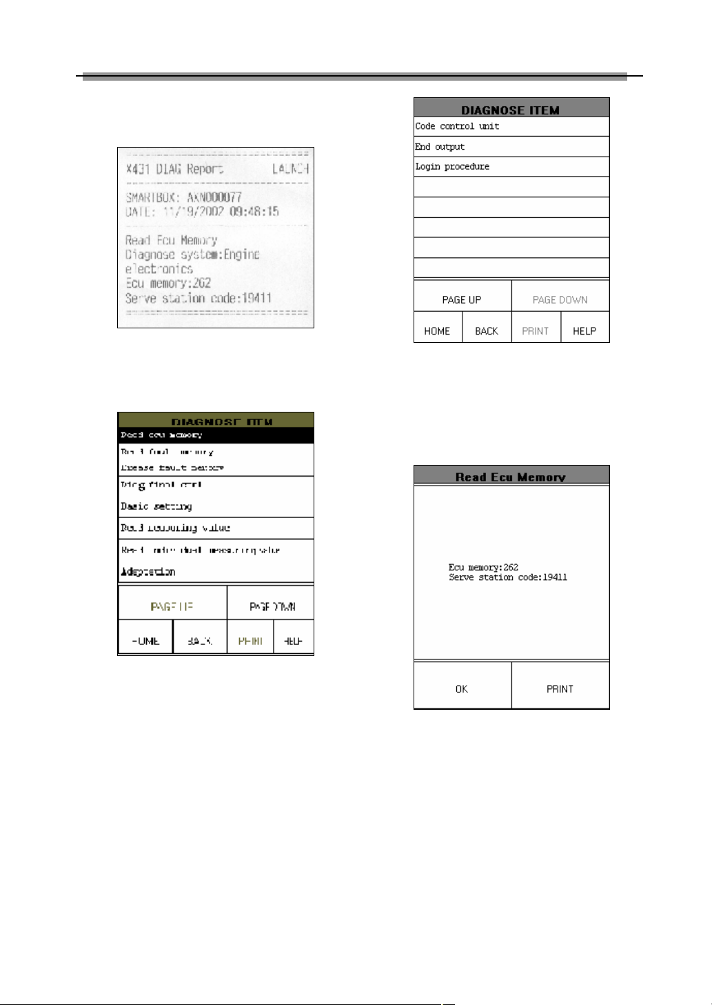
Figure 2-11 shows an example of printed
report.
Figure 2-11
Click [OK] button. The screen will display the
function menu as shown in Figure 2-12.
Figure 2-12
Button descriptions:
♦ [HOME]: to return to the homepage of
vehicle diagnosis.
♦ [BACK]: to return to the previous
interface.
♦ [HELP]: to display the help information.
♦ [PAGE DOWN]: to display the next
page.
Click [PAGE DOWN] button to display the
second page of the function menu as shown in
Figure 2-13.
Figure 2-13
Read ECU Memory
Click [Read ECU Memory] in the function
menu. The screen will display the information
on ECU of the tested system. See Figure 2-14.
Figure 2-14
Note:
The information is from the vehicle ECU. If
you have any question during test, don’t
hesitate to contact LAUNCH to get answer
as soon as possible.
Click [OK] button to return to the function
menu.
Read Fault Memory
Click [Read Fault Memory] in the function
13
Page 17
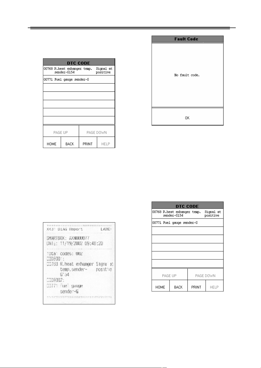
LAUNCH X-431 User’s Manual
menu. X-431 starts to test the fault code. The
screen will display the test result when the test
is finished. Figure 2-15 is an example of a test.
Figure 2-15
Button descriptions:
♦ [HOME]: to return to the homepage of
vehicle diagnosis.
♦ [BACK]: to return to the previous
interface.
♦ [PRINT]: to print the test result.
Click [PRINT] to print out the test result. Figure
2-16 shows an example of printed report.
Figure 2-17
Click [OK] button to return to the function
menu.
Erase Fault Memory
Click [Erase Fault Memory] in the function
menu. X-431 starts to erase the fault code.
The screen will display the residual fault code
after erasing. Figure 2-18 shows an example
of the result after erasing.
Figure 2-16
If there is no fault code in the tested system,
the display will be as shown in Figure 2-17.
Figure 2-18
Button descriptions:
♦ [HOME]: to return to the homepage of
vehicle diagnosis.
♦ [BACK]: to return to the previous
interface.
♦ [PRINT]: to print the test result.
14
Page 18
LAUNCH X-431 User’s Manual
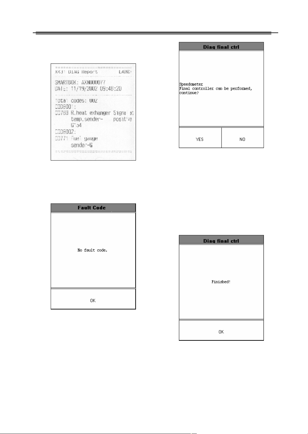
Click [PRINT] to print out the test result. Figure
2-19 shows an example of printed report.
Figure 2-19
If all fault codes are erased or there is no fault
code in the tested system, the screen will be
displayed as shown in Figure 2-20.
Figure 2-20
Click [OK] button to return to the function
menu.
Diagnose Final Control
Click [Diag Final Ctrl] in the function menu.
The screen will display the information as
shown in Figure 2-21.
Figure 2-21
Button descriptions:
♦ [YES]: to perform the test for next
component.
♦ [NO]: to quit the test and return to the
function menu.
When the test for all actuators is finished, the
screen will display the information as shown in
Figure 2-22.
Figure 2-22
Click [OK] button to return to the function
menu.
Basic Setting
Basic setting is necessary for some systems
after service is done.
15
Page 19
LAUNCH X-431 User’s Manual
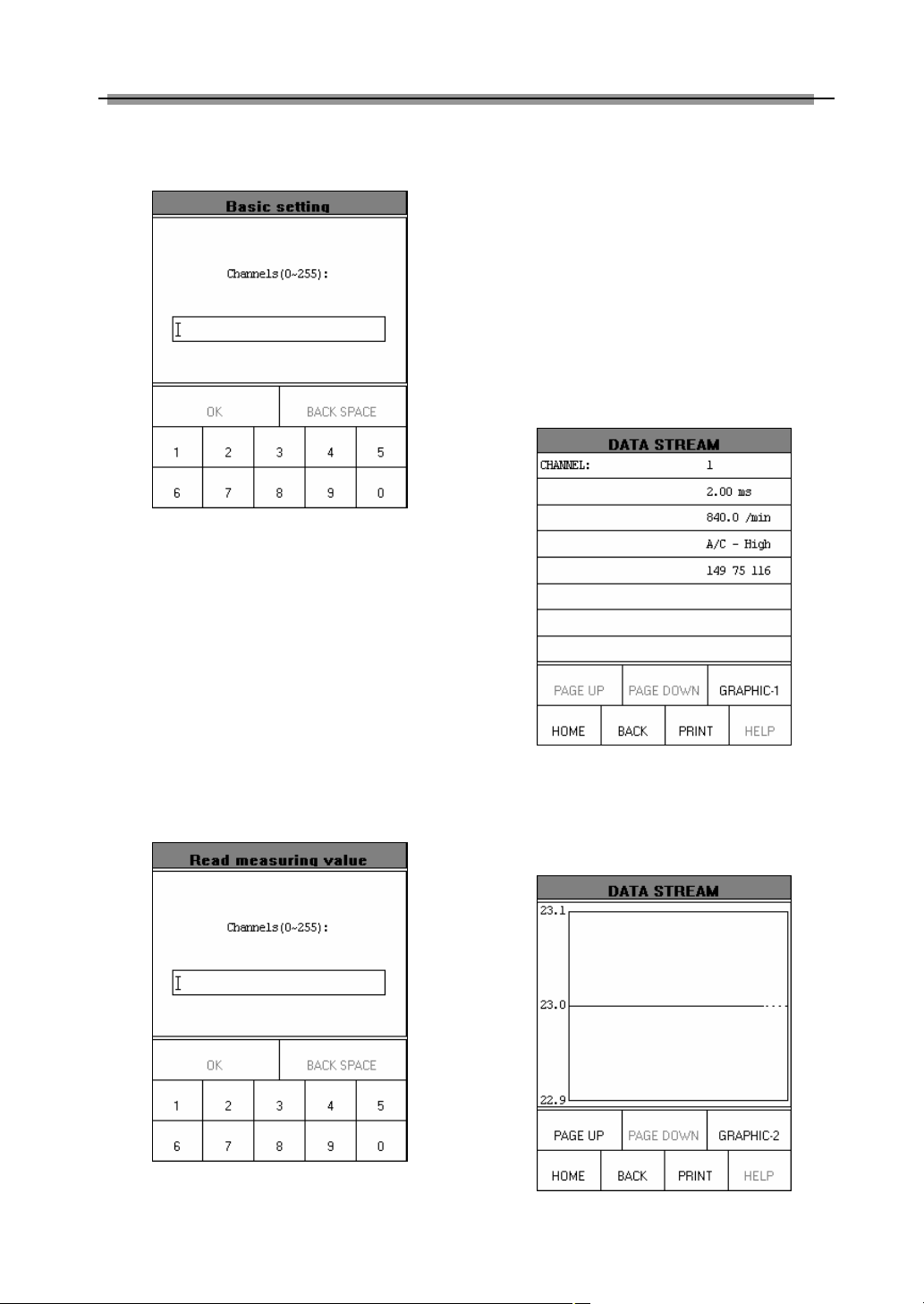
Click [Basic Setting] in the function menu. The
display will be as shown in Figure 2-23.
Figure 2-23
X-431 prompts user to input the channel No.
Click the number button to input the group No.
If wrong number is inputted, click [BACK
SPACE] to delete the wrong number and input
the correct one. After the correct channel No.
is inputted, click [OK] button to perform the
basic setting for the system.
X-431 prompts user to input the channel No.
of data stream. Click the number button to
input the group No. If wrong number is
inputted, click [BACK SPACE] to delete the
wrong number and input the correct one. After
the correct channel No. is inputted, click [OK]
button to perform the function of “read
measuring value”.
For example, when “1” is inputted for the
channel No., the screen will display the live
value of data stream of the channel. See
Figure 2-25.
Read Measuring Value
Click [Read Measuring Value] in the function
menu. The screen will be displayed as shown
in Figure 2-24.
Figure 2-24
Figure 2-25
For seeing the waveform of an item, click the
item and then click [GRAPHIC-1]. Figure 2-26
shows an example of the waveform.
Figure 2-26
16
Page 20
LAUNCH X-431 User’s Manual
Click [GRAPHIC-2] to display the waveforms
of 2 data stream items. See Figure 2-27. It is
convenient for the user to make live
comparison between two correlative data
stream items.
Figure 2-28
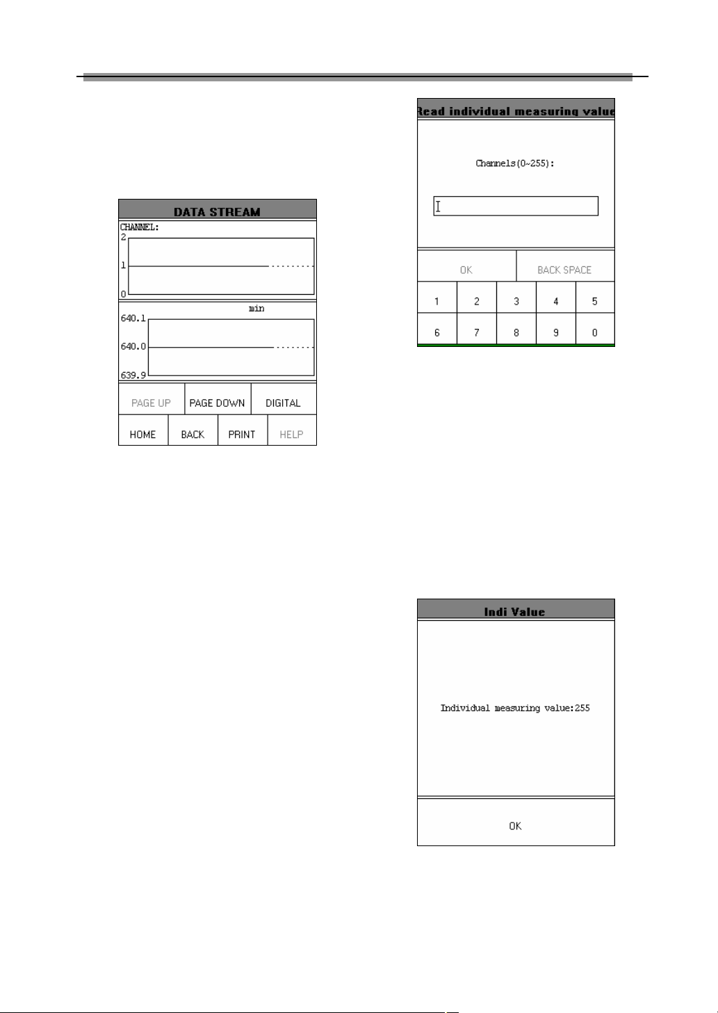
X-431 prompts user to input the channel No.
of data stream. Click the number button to
input the group No. If wrong number is
Figure 2-27
Note:
♦ The screen will display the live value of
data stream again if the [DIGITAL]
button is clicked in the interface.
♦ The three display modes -- [DIGITAL],
[GRAPHIC-1] and [GRAPHIC-2] can be
switched in turn.
inputted, click [BACK SPACE] to delete the
wrong number and input the correct one. After
the correct channel No. is inputted, click [OK]
button to perform the function of “read
individual measuring value”.
For example, when “1” is inputted for the
channel No., the screen will display the live
value of the channel. See Figure 2-29.
Read Individual Measuring Value
Click [Read Individual Measuring Value] in the
function menu. The screen will be displayed as
shown in Figure 2-28.
Figure 2-29
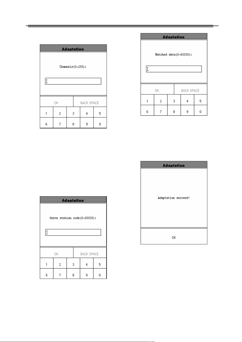
Adaptation
Click [Adaptation] in the function menu. The
screen will be displayed as shown in Figure
17
Page 21
LAUNCH X-431 User’s Manual
2-30.
Figure 2-32
Figure 2-30
X-431 prompts user to input the channel No.
of data stream. Click the number button to
input the group No. If wrong number is
inputted, click [BACK SPACE] to delete the
After the correct channel No. is inputted, click
[OK] button to perform the function of
“adaptation”.
When the adaptation is successful, the screen
will be displayed as shown in Figure 2-33.
wrong number and input the correct one.
After the correct channel No. is inputted, click
[OK] button. X-431 prompts user to input the
service station code. See Figure 2-31.
Figure 2-31
After the code is inputted, click [OK] button.
X-431 prompts user to input the matched data.
See Figure 2-32.
Figure 2-33
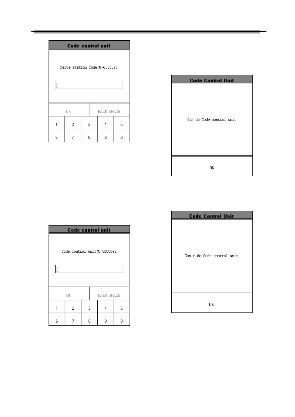
Code Control Unit
Click [Code Control Unit] in the function menu.
The screen will be displayed as shown in
Figure 2-34.
18
Page 22
LAUNCH X-431 User’s Manual
control unit”.
If the control unit can be coded, the screen will
be displayed as shown in Figure 2-36.
Figure 2-34
X-431 prompts user to input the service station
code. Click the number button to input the
service station code. If wrong number is
inputted, click [BACK SPACE] to delete the
wrong number and input the correct one.
After the service station code is inputted, click
[OK] button. X-431 prompts user to input the
Figure 2-36
If the control unit can’t be coded, the screen
will be displayed as shown in Figure 2-37.
control unit code. See Figure 2-35.
Figure 2-35
Click the number button to input the control
unit code. If wrong number is inputted, click
[BACK SPACE] to delete the wrong number
and input the correct one.
After the correct control unit is inputted, click
[OK] button to perform the function of “code
Figure 2-37
End Output
Click [End Output] in the function menu. X-431
will return to the menu of tested systems.
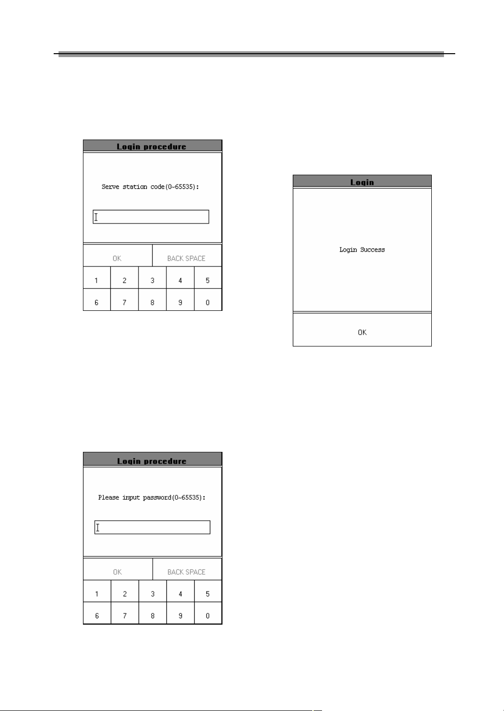
Login Procedure
Note:
Perform this function first before
performing the functions like “code control
19
Page 23
LAUNCH X-431 User’s Manual
unit”, “adaptation”, etc.
Click [Login Procedure] in the function menu.
The screen will be displayed as shown in
Figure 2-38.
Figure 2-38
X-431 prompts user to input the service station
code. Click the number button to input the
service station code. If wrong number is
inputted, click [BACK SPACE] to delete the
wrong number and input the correct one.
After the service station code is inputted, click
[OK] button. X-431 prompts user to input the
password. See Figure 2-39.
password. If wrong number is inputted, click
[BACK SPACE] to delete the wrong number
and input the correct one.
After the login password is inputted, click [OK]
button. X-431 starts to log in. When the login
is successful, the screen will display the
information as shown in Figure 2-40.
Figure 2-40
Click [OK] button to return to the function
menu.
Figure 2-39
Click the number button to input the login
20
Page 24
LAUNCH X-431 User’s Manual
Update of Diagnostic
Software
The Internet update function of X-431 provides
user with a convenient and quick way to
download the software from our website for
update.
LAUNCH put the latest version of software to
www. X431. com and display the massage on
the news page. User can use computer to visit
the Website in any part of the world. After
registration, the latest version of software can
be downloaded. Then user can update his
X-431 by unzipping and installing the software.
Hardware Requirement
Necessary hardware:
1. A computer that can access the Internet.
2. A CF card reader/writer and a CF card that
need to be updated.
See Figure 3-01 for hardware connection.
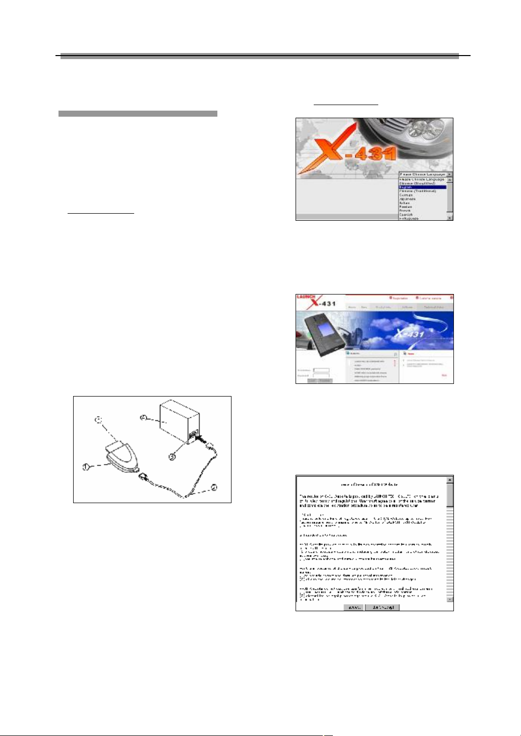
User Registration
Log on www. X431. com. See Figure 3-02
Figure 3-02
Select the favorite language in the pull-down
menu at the lower right of the interface to
enter the homepage. See Figure 3-03.
Figure 3-03
Figure 3-01
1-CF card reader/writer 2-USB cable
3-USB Port 4-Computer 5-CF card
l Insert the CF card into the CF card
reader/writer.
l Connect one end of the USB cable② to
the port of the CF card reader/writer①,
and the other end to the USB port of the
computer.
Read Terms of Service
Click “Register” in the interface shown in
Figure 3-03 to open the window as shown in
Figure 3-04.
Figure 3-04
Note:
When the member purchases one or more
products after registration, he should log
onto the member area, and then click
21
Page 25
LAUNCH X-431 User’s Manual
“product control” to register the newly
purchased product. Refer to the section
“Member login”.
The terms of service is shown in the screen.
After reading and fully understand it, click “I
accept” button to enter the interface shown in
Figure 3-05.
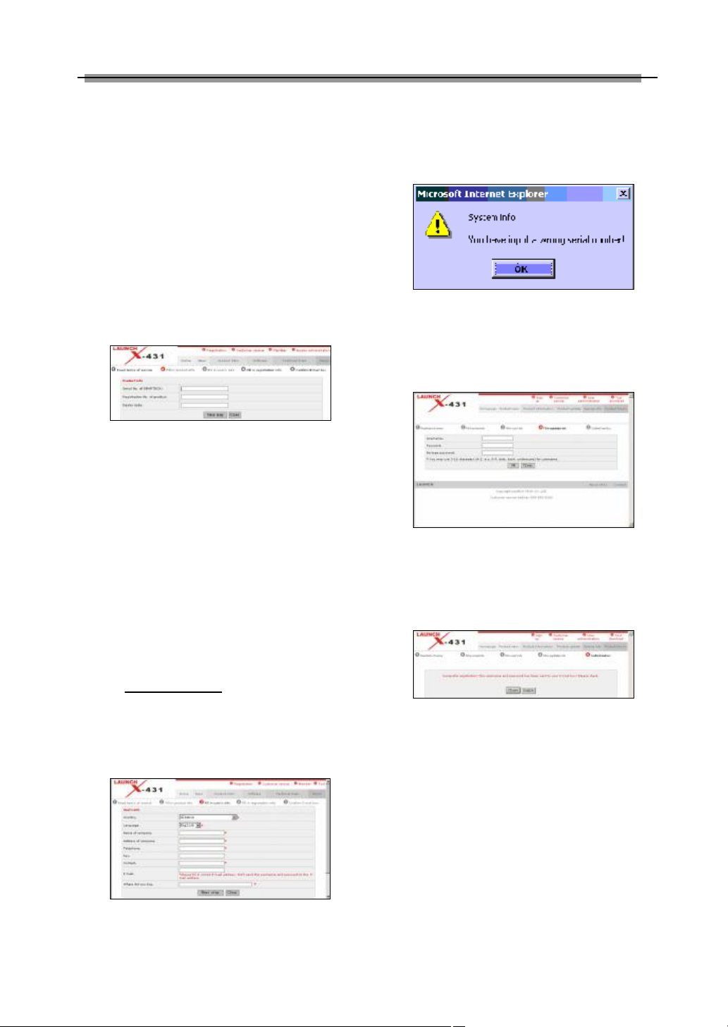
Fill in Necessary Information
Fill in the serial No. of SMARTBOX,
registration No. and dealer code in the
interface shown in Figure 3-05.
Figure 3-05
The serial No. of SMARTBOX is marked on
the back of SMARTBOX. The registration No.
is in an envelope delivered with the product
(the number must be kept confidential). The
dealer code is attached on the last page of the
user’s manual.
After the information is filled, click “Next step”
to enter the next interface shown in Figure
3-06.
Note:
When a product is sold, the dealer will log
onto www. X431. com and enter the dealer
code in the “Dealer administration” area so
that the user can do effective registration
later. User should contact the dealer if
registration can not be done effectively.
invalid, the screen will display the message as
shown in Figure 3-07. Click “OK” button to
return to the previous interface to re-fill the
correct numbers.
Figure 3-07
After information are filled in the interface
shown in Figure 3-06, click “Next step” to enter
the next interface. See Figure 3-08.
Figure 3-08
Fill in the username and password. Then click
“OK” button to enter the interface shown in
Figure 3-09.
Figure 3-09
Up to now, the registration is completed. Click
“Login“ to perform further operation or click
“Close” to exit.
Note:
Only the registered user can download and
update the software.
Figure 3-06
If the filled serial No. or registration No. is
Member Login
The user becomes the registered member
after registration.
Member can log in the website by filling
22
Page 26
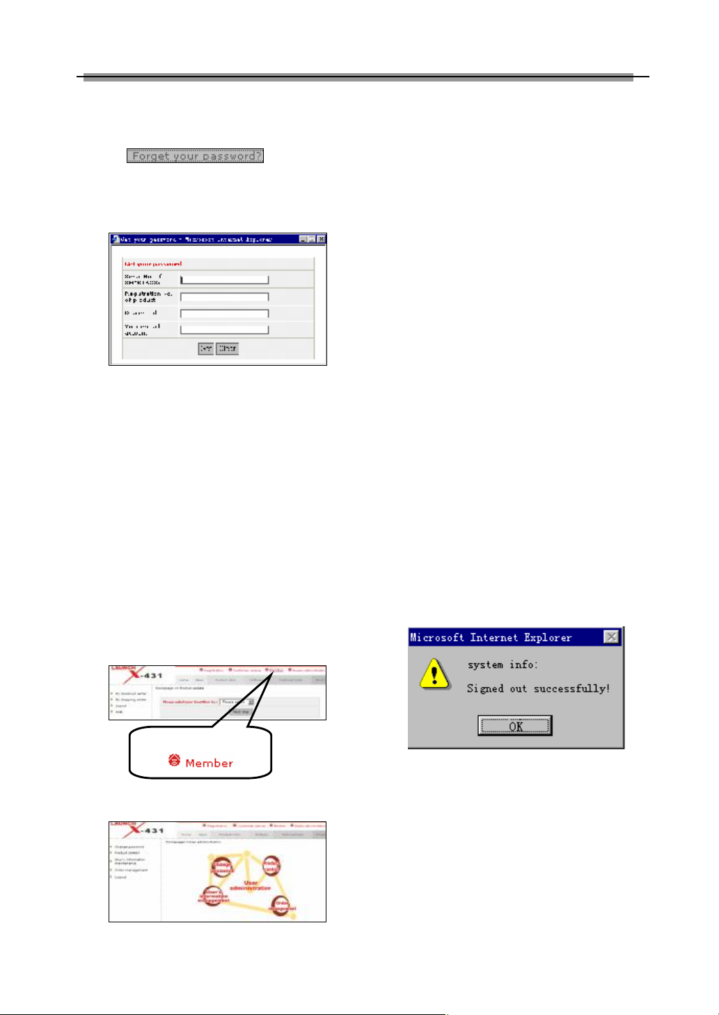
LAUNCH X-431 User’s Manual
Click here to enter
username and password in the interface
shown in Figure 3-03.
Click if you forget
your password, and fill in necessary
information in the pop-up dialogue box shown
in Figure 3-10.
Figure 3-10
Note:
The E-mail account is very important as
our webmaster will send the username and
password to the account.
Member Area
When a registered member purchase one or
more new products, it is not necessary to click
“Register” on the homepage to register the
newly purchased product. Instead, he can
enter username and password to log in, and
then click “member” in the interface shown in
Figure 3-11 to get into the member area. See
Figure 3-12.
The member can perform the following
function:
l Account administration
l Product control
l User’s information maintenance
l Order management
l Logout
Account Administration
It is for changing password.
Product Control
The following tasks can be performed for
“Product Control” function:
l Register newly purchased product.
l Hand over the machine to other customer.
l Click serial No. to see the currently
available software version.
User’s Information Maintenance
It is for renewing the user’s information.
Order Information
It is for checking the unpaid order.
Logout
When clicking “Logout”, the system will pop up
a dialogue box as shown in Figure 3-13.
Figure 3-11
Figure 3-13
Click “OK” button to return to the hompage.
Software Download
Newly registered user can download, free of
charge, the same software as that installed in
the purchased main unit, or the available later
Figure 3-12
version of the software.
23
Page 27
LAUNCH X-431 User’s Manual
After filling in the username and password,
click “Login” to enter the interface as shown in
Figure 3-14.
Figure 3-14
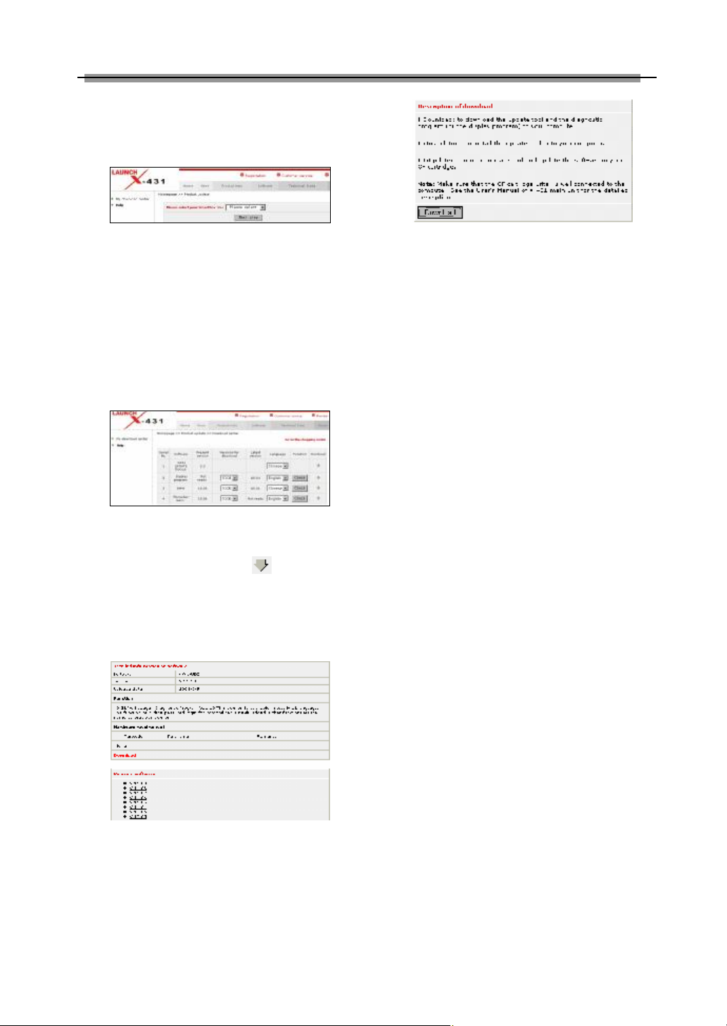
Select the SMARTBOX No. in Figure 3-14 and
then click “Next step” to enter the web page of
software download.
The screen will show a list of software and
different versions for downloading. See Figure
3-15. If no later version is released, the item
will be marked “Not ready”.
Figure 3-15
Select the latest version and language, and
then click “Download” icon ( ) to open the
function introduction page for the software.
The information on the page includes new
function, tested vehicle, hardware requirement,
etc. See Figure 3-16.
Figure 3-16
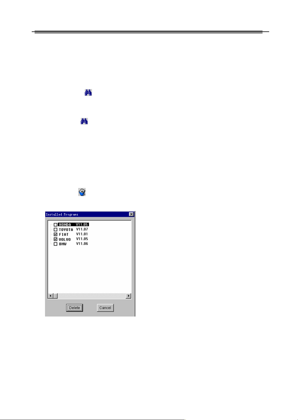
A new page will appear when user clicks
“Download” button. The pop up window will
show the description for updating the
downloaded software. See Figure 3-17.
Figure 3-17
Click “Download” button to save the software
into the user’s computer.
It is necessary to download the “X-431 Update
tool” and put it in the same folder (e.g. “X-431
update” folder) as other downloaded software
if it does not exist in your computer. It is going
to be used later during updating.
Precaution on operation of the CF card
reader/writer:
1)Install the driver
If it is the first time to use the CF card
reader/writer, you may have to install its driver.
Use CD-ROM or floppy disk which are bought
separately or delivered with the CF card
reader/writer to install the driver.
CF card reader/writer can use the default
driver in Windows Me/2000/XP and Mac OS
9.x/Mac OS X. However, it is necessary to
install the driver on Windows 98.
The installation procedure is as follows:
1. Boot Windows 98.
2. Insert the CD-ROM into CD-ROM drive.
3. Connect CF card to the USB port of the
PC with the attached USB cable.
4. Find and Double click on setup.exe file in
the catalogue of CD-ROM. The system will
make preparation for the installation. See
Figure 3-18.
5. When the preparation is complete, the
screen will prompt to continue the
operation. See Figure 3-19. Click “Next” to
start installation.
24
Page 28

LAUNCH X-431 User’s Manual
♦ Data on CF card cannot be restored from
the “Recycle Bin” once deleted.
2)Pull out the CF card
The CF card must not be pulled out when the
CF card reader/writer is being used. Otherwise,
the data in the CF card will be lost.
Figure 3-18
Procedure for pulling out the CF card:
On the desktop of Windows, open the window
of “My computer”. Click the right mouse button
on “Removable disk” to pop up a menu. Select
“Ejector (J)” in the menu. Then pull out the CF
card. The written data may be lost if the CF
card is pulled out discretionarily. When you
want to use the CF card again, put it in.
Software Update
Open the “X-431 update” folder, and double
Figure 3-19
6. When installation is finished, the screen
will display the information as shown in
Figure 3-20. Click “Finish” to exit.
Figure 3-20
When the CF card reader/writer is installed
successfully, a “Removable disk” icon
will be added in the catalogue of “My
computer”.
Note:
♦ Do not unplug the CF card reader/writer
from the USB port while its LED is
blinking, otherwise data would be
damaged!
click the icon . Then install the update tool
according to the prompts on the screen.
When the installation is complete, the “X-431
update tool” icon will appear on the
desktop.
Make sure that the X-431 CF card
reader/writer and the CF card are well
connected to the computer. Then double click
the “X-431 update tool” icon to run the
program. The program will automatically check
the downloaded update files, including the
diagnostic program and the display program.
See Figure 3-21.
Figure 3-21
Select the module for update in the interface
25
Page 29
LAUNCH X-431 User’s Manual
shown in Figure 3-21, and click “Update” icon
to update. When the update is complete,
prompts will appear to notify successful
update.
Description of icons at the lower left of the
interface:
♦ Source folder : to show the route
that the update program is from. The
default one is where the last software
from.
♦ Target folder : to show the route that
the update program will be installed. It is
CF card in this situation. It is necessary
to click this button to designate the
removable disc when laptop computer is
used.
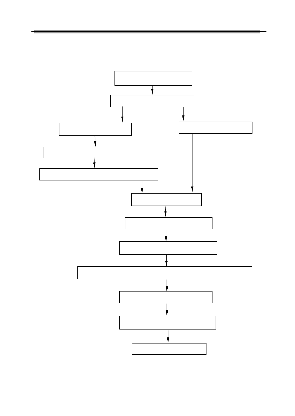
The required space and available space are
listed at the lower left of the interface. If the
available space is not enough to perform the
operation, click to show the installed
programs. See Figure 3-22.
Figure 3-22
Select the programs that can be deleted and
click “Delete” button to make some more
space available.
26
Page 30
LAUNCH X-431 User’s Manual
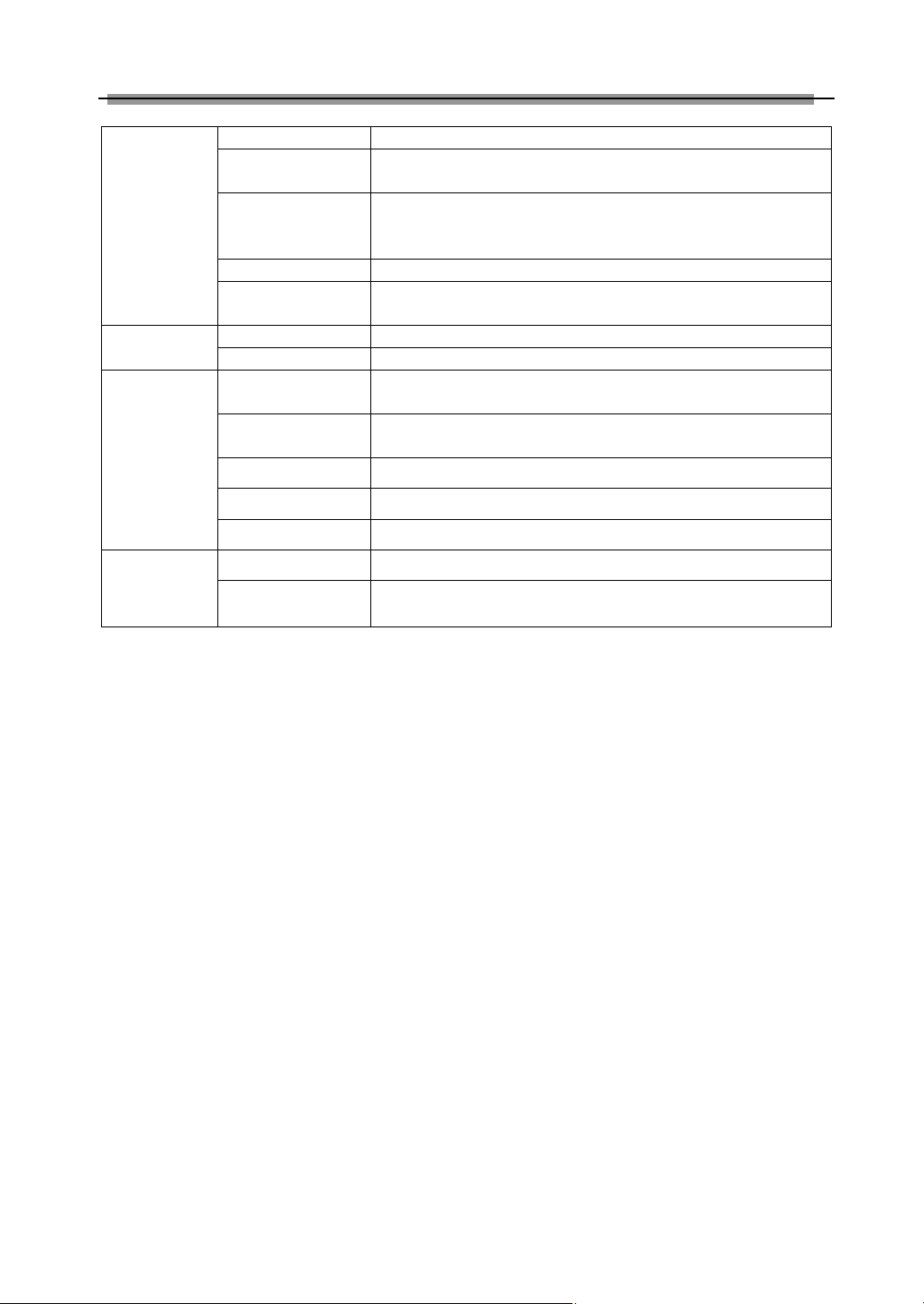
For unregistered user
For member
Select language
Install and run
X431
update tool
Select
SMARTBOX
Serial No.
Complete the registration
Read terms of service, click [I accept]
Enter username and PW
After update, press [ESC]
Click
[
Login]
Flow Chart of X-431 Update for New User
Click [Register]
Log on www. x431. com
Connect CF card writer and CF card,install CF card writer driver
Download software and update tool
Select module and perform update
27
Page 31

LAUNCH X-431 User’s Manual
Main Unit
Introduction
Interface
Turn on the power source, and then press
[Power] key on the machine. The screen will
display the prompts about touch screen
calibration. Press [Hot] key (refer to the
section “Calibrate Touch screen” for detailed
steps) if you want to make calibration,
otherwise, you can wait until it displays the
start interface as shown in Figure 4-01.
Figure 4-01
Functions:
To record all kinds of important information and ideas, and make
corresponding classification.
To store the detailed information of relative, friends, colleagues
and business partners, which can be easily edited, retrieved and
searched.
It is convenient for user to record the business to do or being
done, to delete or add task records, to arrange the priority of
tasks, and to browse the classified tasks.
To arrange the appointments, journeys and meetings in a whole
day; to check time schedule on business daily, weekly, monthly
and/or annually; and to describe the place, time and other
details for each schedule record.
PIM
(Personal
Information
Management)
Memo
Address
To Do
Schedule
Note:
An interface for User Register will be
displayed when the machine is started at
first time. Refer to the section “User
Register” for detailed steps.
When you want to turn off the machine, press
and hold [Power] key for at least 2 seconds.
[Start] button: Its function is the same as that
in Windows. Click it to pop up the start menu.
The items and their respective functions in the
menu are shown in the following table.
[ ] Active Taskbar Icon: Click it by stylus to
display and switch the executed programs.
[ ] Back Light Icon: Click it to turn on/off
back light.
[ ] Soft Keyboard Icon: Click it to activate
the soft keyboard. Then you have two ways to
choose:
1. Input by soft keyboard;
2. Input by writing board.
28
Page 32
LAUNCH X-431 User’s Manual
Calculator Both simple and scientific calculators are available.
World Time
The time of many big cities in the world are offered. It is a helpful
assistant for your travel.
An English-Chinese dictionary embodies a large number of
Tools
Mini Dictionary
words, which cover all fields to overcome your inconvenience in
language.
Picture View To enjoy all kinds of pictures which can be zoomed in/out.
To start executable applications which are based on the
operating system of the unit.
To link the application with the ‘Start’ menu, or delete it from the
‘Start’ menu.
To preset the use of power to save on electricity as possible.
To set the system time.
Game
Control Panel
Run
FIR It is a kind of chess.
Reversi To play for a while in your leisure time.
Application
Power
Management
Clock Set
Contrast To adjust the contrast of display.
To select language to be used.
Professional function of vehicle diagnosis.
To test the sensor on vehicle and simulate the output signal from
the sensor.
Vehicle
maintenance
Language Set
Vehicle diagnosis
Sensor test and
simulation
29
Page 33

LAUNCH X-431 User’s Manual
key at the bottom right of the Soft Keyboard is
Input
Note: To input data, please activate Soft
Keyboard with stylus and use the stylus in
the subsequent operations.
Using the Soft Keyboard
space key.
Activate and Hide
You can click Soft Keyboard icon on the bottom
of the touch screen to activate the soft
keyboard, and click again to hide it.
Input by Soft Keyboard
You have two ways to choose. One is to input
by Soft Keyboard just like normal keyboard, but
with stylus instead of finger. The other is to
input by writing board.
Click [En] button, it will switch from normal
keyboard to writing board [Hw]. And click [Hw]
button, it will switch back.
The Function Key
There are four function keys on the upper-right
of the Soft Keyboard. SBC/DBC case,
punctuations, Keyboard/Writing board, and the
Soft Keyboard position can be determined by
clicking one of the four keys for each of the
functions from left to right. (Refer to Figure
4-02)
The four function keys at the upper-middle
position are for moving the cursor leftward,
rightward, upward or downward.
Figure 4-03
In writing board mode (refer to Figure 4-03),
there are eight function keys at the lower left of
the soft keyboard. The four ones on the bottom
implement the function: to move the cursor
leftward, rightward, upward or downward. The
other four functions are (from left to right): to
delete the first character before the current
cursor, clear the hand-writing section, space
and return.
Input by Keyboard
1) Open an interface, such as User
information.
2) Click Soft Keyboard Icon in the tool bar to
activate Soft Keyboard.
3) Click the characters on Soft Keyboard to
enter data. (Refer to Figure 4-04)
Input by Writing Board
1) Open an interface, such as Memo.
2) Click [New] button.
3) Click the function key to switch to Writing
Board. (Refer to the section “Use for Soft
Keyboard”).
4) Write on the white board to the right of the
Soft Keyboard. Enter the information by
function key operation.
Figure 4-02
In keyboard mode, the key at the bottom left of
the keyboard is [Shift] key. Click it to change the
lowercase letter into the uppercase letter, and
the numeral key into special symbol (same as
the special characters corresponding to the
numeral keys in normal keyboard). The white
30
Page 34
LAUNCH X-431 User’s Manual
Figure 4-04
Control of App
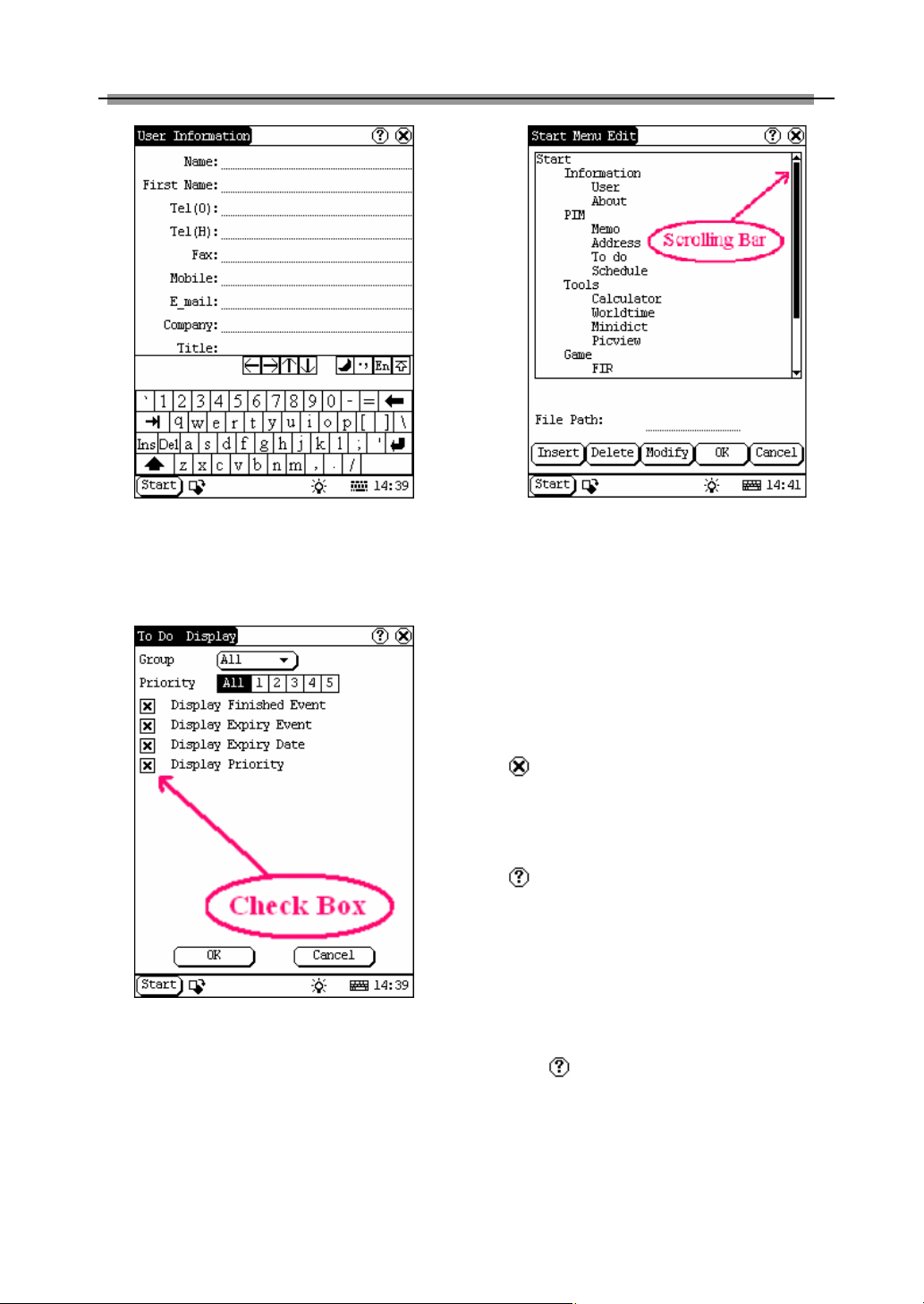
Check Box
Figure 4-05
Click the check box to select the function. When
the function is selected, 'X ' will be marked in
the check box and the function description will
be displayed on the right of the check box. You
can select several functions at the same time.
(Refer to Figure 4-05)
Scrolling Bar
Scrolling Bar is usually at the right side of the
touch screen. You can click or drag it to operate.
If the content can’t be displayed completely in
one page, moving the Scrolling Bar can turn to
next page. (Refer to Figure 4-06)
Common Button
[ ] Button at top right corner of the interface:
After clicking it, current interface will be closed.
When editing is being done, clicking of the
button will be treated as quitting the editing.
[ ] Button at top right corner of the interface:
After clicking it, the help information will be
shown.
[Cancel] Button in the interface: After clicking it,
current interface will be closed.
Help
Click [ ] button at the top right corner of the
interface to get helpful tips for current interface.
Figure 4-06
31
Page 35

LAUNCH X-431 User’s Manual
Tool and Game
Tools
Figure 4-07
1) Click [Start] button.
2) Select ‘Tools’ in the pop-up menu.
3) Select the function needed in the pop-up
submenu. (Refer to Figure 4-07)
Calculator
This calculator can perform not only common
calculations as a simple calculator, such as
addition and subtraction, but also the function
operations as a scientific calculator, such as
logarithm and factorial. (Refer to Figure 4-09).
1) In the pop-up menu of ‘Tools’, select
‘Calculator’ to open the Calculator
interface.
2) Click the square overlap icon on upper
left of the screen to switch between
scientific calculator and simple calculator.
3) Click ‘Unit Conversion’ button to switch
between unit conversion calculator and
simple calculator.
Figure 4-08
Figure 4-09
Common Calculator (Refer to Figure 4-08):
1) Click numeral keys on the screen to input.
2) Or activate Soft Keyboard, and click
numeral key on Soft Keyboard to input.
3) The operation is the same as that for
normal calculator.
Unit Conversion Calculator (Refer to Figure
4-10):
1) Click ‘Unit type’ button at the top right
corner to select unit type.
32
Page 36

LAUNCH X-431 User’s Manual
2) Input the number to be converted in the
blank next to the unit name, and then you
will see the conversion result.
3) If you want to return to simple calculator,
please click 'X' button at the top right
corner to close the current interface.
Figure 4-10
interface.
2) Click the button under the ‘Home Time’
icon to select region.
3) Click the button under the ‘World Time’
icon to select region.
4) Then you can see the time directly. (See
Figure 4-11).
Dictionary
1) In the pop-up menu of ‘Tools’, select
‘Dictionary’ to open the Dictionary
interface. (See Figure 4-12)
2) Activate Soft Keyboard, and input words.
3) Select the word from the list on the left.
4) Click the word, and then you can find the
translation in the right list.
World Time
Figure 4-11
1) In the pop-up menu of ‘Tools’, select
‘world time’ to open the world time
Figure 4-12
Picture View
1) Click [Start] button.
2) Select ‘Tools’ in the pop-up menu. (See
Figure 4-13)
3) In the pop-up ‘Tools’ list, select ‘Picview’ to
open the Picture interface.
4) In the Picture interface, click icon in
the toolbar on the top. (See Figure 4-14)
5) Select directory from the left list interface.
6) Select file from the right list interface.
7) Click [Parent Dir] button, and you can see
the directory of current directory’s parent.
8) You can see the directory of the picture at
the right side of ‘Path’.
33
Page 37

LAUNCH X-431 User’s Manual
9) You can see the file name of the picture at
the right side of ‘File’.
10) Click [OK] button to open the picture.
Figure 4-13
than one picture has been stored.
Zoom in and zoom out:
In the Picture interface, click or icon
on the top, then you can zoom in or zoom out
the current picture at will.
Game
Figure 4-14
Browse the pictures in current directory
1) In the Picture interface, click icon on
the top to browse the previous picture.
2) In the Picture interface, click icon on
the top to browse the next picture.
Note:
This operation is needed only when more
Figure 4-15
1) Click [Start] button.
2) Select ‘Game’ in the pop-up menu.
3) Select the function in the pop-up
submenu. (See Figure 4-15)
FIR
1) In the pop-up submenu of ‘Game’, select
‘FIR’ to open the Chess Board.
2) Click black or white chessman to begin
the game. The one who select the black
chessman will start first. (See Figure
4-16)
Rules for the game:
You must try to make your five chessmen line
up and prevent your adversary from achieving
this goal in the process. The one whose 5
chessmen are lined up first is winner. You can
choose the black or white chessman at the
bottom of the Chess Board before starting
playing.
34
Page 38

LAUNCH X-431 User’s Manual
first. All black chessmen between two white
chessmen will turn to white ones and all white
chessmen between two black chessmen will
turn to black ones. So the player should be able
to reverse adversary‘s chessmen in each step.
When the chessboard is full of chessmen, the
number of the chessmen for each color should
be counted. The one who conserve more
chessmen on the chessboard is winner.
PIM
1) Click [Start] button.
2) Select ‘PIM ’ in the pop-up menu.
3) Select the function needed in the pop-up
list. See Figure 4-18.
Figure 4-16
Figure 4-17
Reversi
1) In the pop-up menu of ‘Game’, select
‘Reversi’ to open the Chess Board. (See
Figure 4-17)
2) Click [New Game] button to start.
3) Click [Undo] button for pull back.
4) Click [Close] button to close the Chess
Board.
Rule:
The one who chooses white chessman can play
Figure 4-18
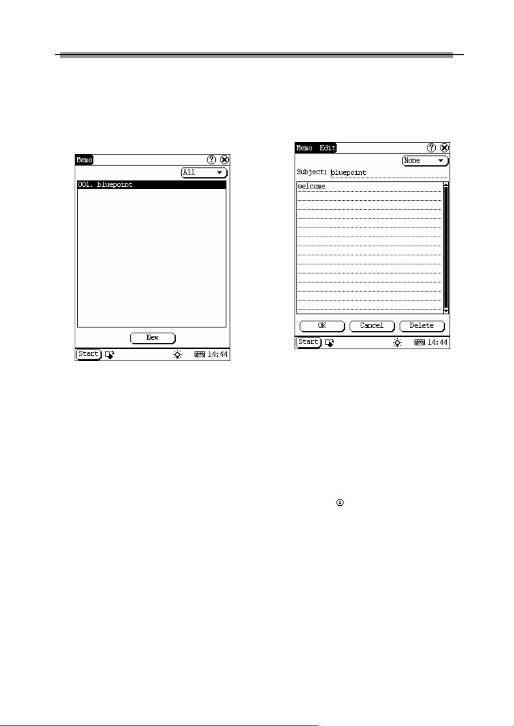
Memo
The basic functions of Memo include: add new
memo, view memo, delete memo, browse by
types, etc.
1) In the pop-up ‘PIM’ list, select ‘Memo’ to
open the Memo interface. (See Figure
4-19)
2) After you click the [▼] button on top right
corner, the type list will pop up. Then you
can select the type of the memo.
3) You can also select the Edit Group in the
type list to open the Edit Group interface.
4) The memo list of corresponding type will
35
Page 39
LAUNCH X-431 User’s Manual
be displayed in the list box on the midst of
the Memo interface.
5) Click one memo in the memo list to open
the Memo Edit interface.
6) Click [New] button to open the New Memo
interface.
Figure 4-19
Add New Memo
1) In the Memo interface, click [New] button
to open the New Memo interface.
2) Activate Soft Keyboard, and fill the
subject and contents.
3) Click the button on top right corner, then
select the type in the pop-up list
4) Click [OK] button to save and close the
New Memo interface.
5) Then you can see the new memo in the
list box of the Memo interface.
View Memo
1) In the list box of the Memo interface, click
the memo that you want to view.
2) Then you can view the contents of the
memo in the opened Memo Edit interface.
3) Click [OK] button to close the Memo Edit
interface.
Edit Memo
1) In the list box of the Memo interface, click
the memo that you want to edit.
2) Then you can edit the contents of the
memo in the opened Memo Edit interface.
See Figure 4-20.
3) After editing, click [OK] button to save the
edited contents and close the Memo Edit
interface.
Figure 4-20
Delete Memo
1) In the list box of the Memo interface, click
the memo that you want to delete.
2) Then you can delete the memo in the
opened Memo Edit interface.
3) Click [Delete] button to delete the memo
and close the Memo Edit interface.
Edit Type
1) Click the [▼] button on the top right of the
interface so that the type list pops up.
2) In the type list, select the Edit Group to
open the Edit Group interface.
3) In the Edit Group interface, activate Soft
Keyboard.
4) In the text box at the bottom of the
interface, input the name of the type.
5) Click [Add] button to add a new type and it
will be displayed in the list box of the Edit
Group interface. (See Figure 4-21)
6) Select one type in the list box, and then
click [Delete] button to delete it.
7) Click [Close] button to close the Edit
Group interface.
36
Page 40

LAUNCH X-431 User’s Manual
The interface : It represents the Memo
Interface, the New Memo interface and the
Memo Edit interface.
Figure 4-21
Browse By Types
1) Click the [▼] button on the top right of the
Memo interface so that the type list pops
up.
2) Select the type in the list.
3) Then you can see the memo belonging to
the type in the list box.
Note: Only the memo belonging to the type
can be displayed here. If you want to browse
all memos, please select ‘All’ in the steps 1
and 2.
The operation guide for each function is
described below:
Figure 4-22
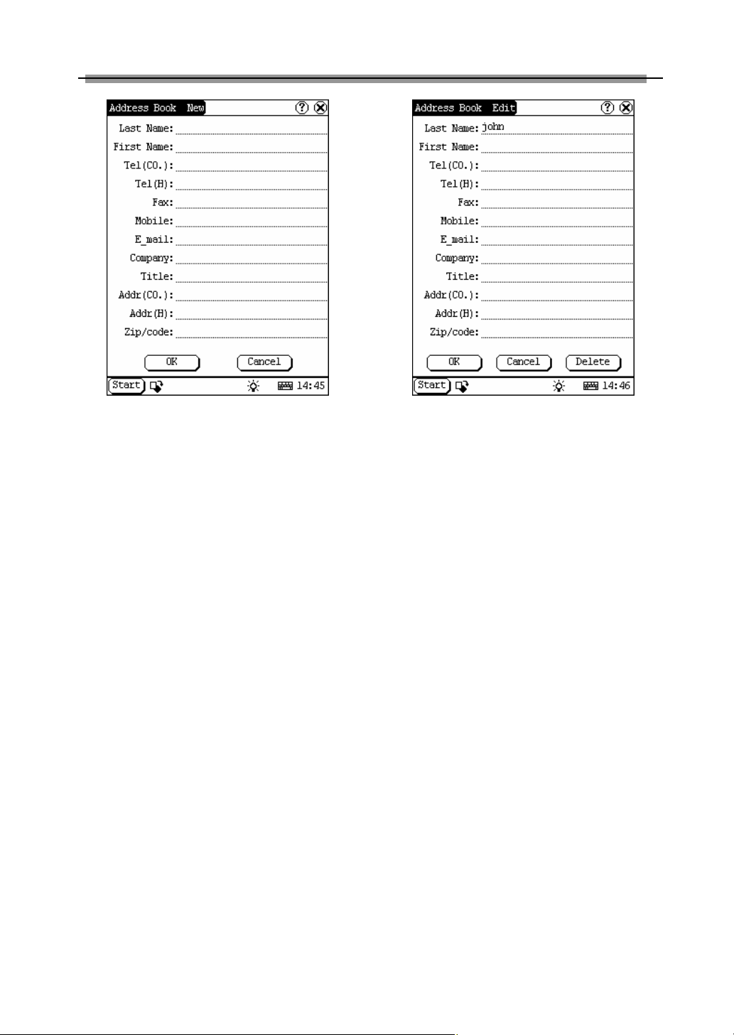
Add New Address
1) In the Address Book interface, click [New]
button to open the Address New interface.
(See Figure 4-23)
2) Activate Soft Keyboard, and fill the
detailed information on relatives and
friends.
3) Click [OK] button to save and close the
Address New interface.
4) Then the added name will be displayed in
the list box of the Address Book interface.
Address
The basic functions of Address Book include:
add new address, view address, delete address,
to search address, etc.
1) In the pop-up ‘PIM’ list, select ‘Address’ to
open the Address Book interface.
2) It lists the name of persons whose
communication information has been
stored.
3) Click [New] button to open the Address
New interface. (See Figure 4-22)
4) Click [Find] button to pop up the Find
People interface.
37
Page 41
LAUNCH X-431 User’s Manual
Figure 4-23
View Address
1) In the list box of the Address Book
interface, click the name that you want to
view.
2) Then the detailed information about the
person will be shown in the opened
Address Edit interface.
3) Click [OK] button to close the Address
Edit interface.
Edit Address
1) In the list box of the Address Book
interface, click the name that you want to
edit.
2) Then the information about the person
can be edited in the opened Address Edit
interface. See Figure 4-24.
3) After editing, click [OK] button to save the
edited contents and close the Address
Edit interface.
Figure 4-24
Delete Address
1) In the list box of the Address Book
interface, click the name that you want to
delete.
2) Then the information about the person will
be shown in the opened Address Edit
interface.
3) Click [Delete] button to delete the
person’s information and close the
Address Edit interface.
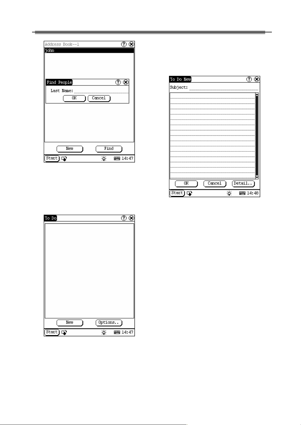
Search Address
1) In the Address Book interface, click [Find]
button to pop up the Find People interface.
See Figure 4-25.
2) Activate Soft Keyboard, and input the
name you want to search.
3) Click [OK] button, and then you will see
that the name you search is highlighted in
the list box.
38
Page 42
LAUNCH X-431 User’s Manual
Display interface. (See Figure 4-26)
4) Click [New] button to open the To Do New
interface.
Add New To Do
Figure 4-25
To Do
The basic functions of To Do include: add new
To Do, view To Do, delete To Do and set To Do,
etc.
Figure 4-26
1) In the pop-up ‘PIM’ list, select ‘To Do’ item
to open the To Do interface.
2) The To Do list of corresponding items will
be displayed in the list box on the midst of
the Memo interface.
3) Click [Options] button to open the To Do
Figure 4-27
1) In the To Do interface, click [New] button
to open the To Do New interface. See
Figure 4-27.
2) Activate Soft Keyboard, and fill in the
subject and contents.
3) Click [Detail] button to open the To Do
Detail interface. See Figure 4-28.
4) In the To Do Detail interface, click the
button to the right of ‘Group’ to pop up the
type list.
5) Click the button to the right of ‘Expired’,
and select the data in the pop-up list.
6) Click the number to the right of ‘Priority’ to
set the priority of the To Do.
7) If the To Do has been finished, please
click the box to the right of ‘Finished’.
When the function is selected, ‘X’ will be
marked in the box,.
8) Click [OK] button to save and close the To
Do Detail interface.
9) In the To Do Detail interface, click [OK]
button to save and close the To Do New
interface.
39
Page 43
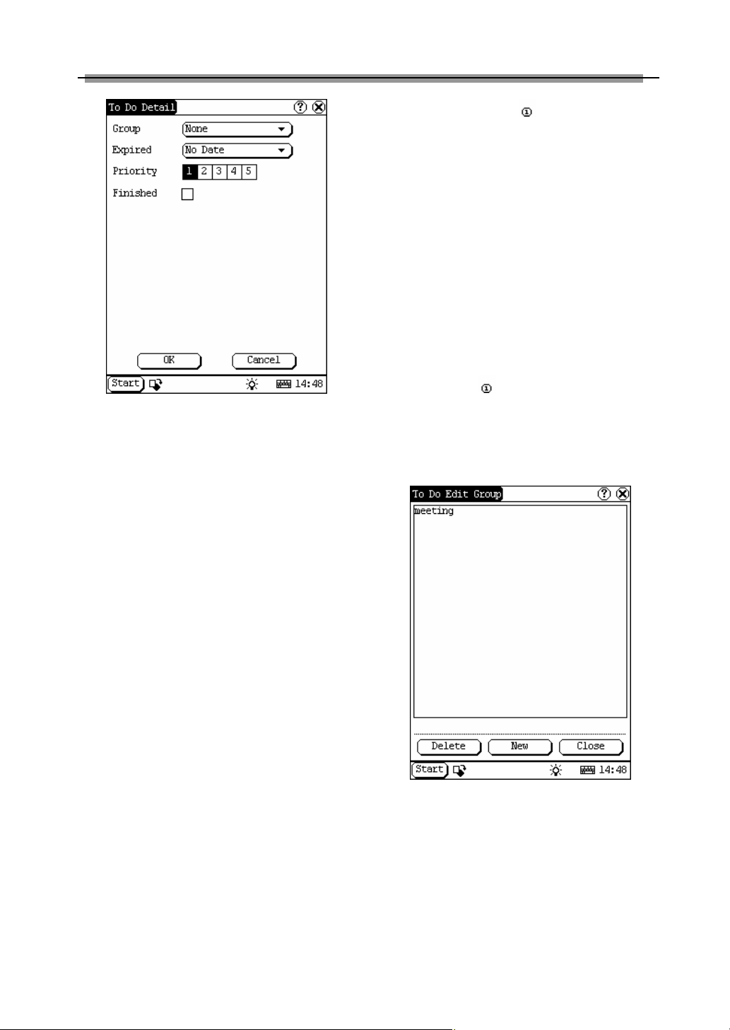
LAUNCH X-431 User’s Manual
in the interface so that the type list
pops up.
2) In the type list, select ‘Edit Group’ to open
the Edit Group interface. See Figure 4-29.
3) In the Edit Group interface, activate Soft
Keyboard.
4) In the text box at the bottom of the
interface, input the name of the type.
5) Click [New] button to add a new type and
it will be displayed in the list box of the
Edit Group interface.
6) Select one type in the list box, and then
click [Delete] button to delete it.
7) Click [Close] button to close the Edit
Group interface.
Figure 4-28
The interface : It represents the To Do
Detail Interface (Refer to step 1-3 in the
section “Add New To Do” and “Edit To Do”),
View To Do
1) In the list box of the To Do interface, click
the to do that you want to view.
and the To Do Display interface (Refer to
step 1 in the section “The Set of Display ”).
2) Then the contents of the To Do will be
shown in the opened To Do Edit interface.
3) Click [OK] button to close the To Do Edit
interface.
Edit To Do
1) In the list box of the To Do interface, click
the memo that you want to edit.
2) Then the contents of the memo will be
shown in the opened To Do Edit interface.
3) Click [Detail] button to open the To Do
Detail interface, please refer to step 4~8
in the section “Add New To Do”.
4) After editing, click [OK] button to save the
edited contents and close the To Do Edit
interface.
Delete To Do
1) In the list box of the To Do interface, click
the to do that you want to delete.
2) Then the contents will be shown in the
opened To Do Edit interface.
3) Click [Delete] button to delete the To Do
and close the To Do Edit interface.
Edit Type
1) Click the [▼] button to the right of ‘Group’
Figure 4-29
40
Page 44

LAUNCH X-431 User’s Manual
The Set of display
Figure 4-30
1) In the To Do interface, click [Options]
button to open the To Do Display
interface.
2) In the To Do Display interface, click the
button to the right of ‘Group’ to pop up
type list, and select the type in the pop-up
list.
3) Click the button to the right of ‘Expired’,
and select the data in the pop-up list.
4) Click the number or ‘All’ to the right of
‘Priority’ to set the priority of the displayed
To Do.
5) Click the box to the right of each function.
When ‘X’ is displayed in the box, the
function is selected. (See Figure 4-30)
6) Click [OK] button to close the To Do
Display interface.
7) Then you can see the corresponding To
Do in the list box of the To Do interface.
Schedule
The basic functions of Schedule include: add
new schedule, view schedule, delete schedule,
etc.
Figure 4-31
1) In the pop-up list of ‘PIM’, select
‘Schedule’ to open the Schedule interface.
2) Click the Date button on the upper left of
the interface to open the Select Date
interface.
3) In the list box in the middle of the
interface, all schedules on that day
corresponding to the Date button will be
displayed. (See Figure 4-31)
4) Click [New] button, and then the cycle list
pops up. You may select ‘Common’,
‘Daily’, ‘Weekly’, ‘Monthly’ and ‘Annual’.
5) In the cycle list, select one item to open
the Schedule New interface.
Add New Schedule
Set the date of the schedule:
1) In the Schedule interface, click the Date
button on the upper left to open the Select
Date interface.
2) In the Select Date interface, click [ ]
icon to the left of the month or year to
select the previous month or year.
3) Click the [ ] icon to the right of the
month or year to select the next month or
year. (See Figure 4-32)
4) Click to select the date in the current
month. When it is highlighted, it is
selected.
5) Or click [Today] button to display the
41
Page 45

LAUNCH X-431 User’s Manual
current year, month and date directly.
6) Click [OK] button to save the date setting
and close the Select Date interface.
7) You may see the date you set on the
button on the top right of the Schedule
interface.
Figure 4-32
Set the cycle of the schedule:
1) In the Schedule interface, click [New]
button so that the Cycle list pops up. See
Figure 4-33.
2) In the Cycle list, select ‘Common’ if it is
done on the selected date.
3) Select ‘Daily’ if it is done every day.
4) Select ‘Weekly’ if it is done on a fixed day
every week.
5) Select ‘Monthly’ if it is done on a fixed day
every month.
6) Select ‘Annual’ if it is done on a fixed day
every year.
7) After selecting, open the New Schedule
interface.
Figure 4-33
Set the content of the schedule:
Figure 4-34
1) In the Schedule New interface, activate
Soft Keyboard, and fill the subject and
contents.
2) In the textbox on the top of the interface,
fill the time of the schedule.
3) If the selected cycle is ‘Daily’, ‘Weekly’,
‘Monthly’ or ‘Annual’, you can input the
repeat time in the textbox on the bottom
of the interface. See Figure 4-34.
42
Page 46

LAUNCH X-431 User’s Manual
4) “Remind” function can be selected and
the reminding time can be set in the
interface. The “Remind” function will not
be available when the machine is turned
off.
5) Click [OK] button to save and close the
Schedule New interface
View Schedule
2) In the Schedule interface, select the date
that has been scheduled. (Refer to the
section “Add New Schedule à Set the
date of the schedule”)
3) In the list box of the Schedule interface,
click Scrolling Bar to turn to next page,
and click the schedule you want to view.
4) Then the contents of the schedule will be
shown in the opened Schedule View
interface.
5) Click [OK] button to close the Schedule
View interface.
Edit Schedule
1) In the Schedule interface, select the date
that has been scheduled. (Refer to the
section “Add New Schedule à Set the
date of the schedule”)
2) In the list box of the Schedule interface,
click Scrolling Bar to turn to next page,
and click the schedule you want to edit.
3) Then the contents of the schedule will be
shown in the opened Schedule View
interface.
4) If the edited affair is ‘Daily’, ‘Weekly’,
‘Monthly’ or ‘Annual’, you can edit the
repeat time in the textbox on the bottom
of the interface.
5) After editing, click [OK] button to save the
edited contents and close the Schedule
View interface.
opened Schedule View interface. See
Figure 4-35.
4) Click [Delete] button to delete it and close
the Schedule View interface.
Figure 4-35
System
Control Panel
The control panel includes all interrelated
software and hardware configurations. It makes
the software more custom-built for you by
configuring.
1) Click [Start] button.
2) Select ‘Control Panel’ in the pop-up menu.
3) Open the Control Panel interface. (See
Figure 4-36)
Delete Schedule
1) In the Schedule interface, select the date
that has been scheduled. (Refer to the
section “Add New Schedule à Set the
date of the schedule”)
2) In the list box of the Schedule interface,
click Scrolling Bar to turn to next page,
and click the schedule you want to edit.
3) Then the schedule will be shown in the
43
Page 47

LAUNCH X-431 User’s Manual
3) Insert a new group:
Click [Insert] button and input the item
name. Then choose “Start” as its parent
and click [OK] button.
Figure 4-36
Application
It displays the application information contained
in the ‘Start’ menu, including the group name,
the submenu, etc.
Figure 4-37
1) In the Control Panel interface, click ‘App’
icon to open the Application Manager
interface.
2) Then you can see the corresponding
information in the list box of the interface.
(See Figure 4-37)
Figure 4-38
4) Insert a new submenu:
Click [Insert] button and input the item
name and the file path. Then choose a
group as its parent and click [OK] button.
The path can be inputted directly or found
out in a dialogue box after clicking
[Browser] button. See Figure 4-38 and
Figure 4-39. Click [OK] button after
selecting an item in the list. Then the
selected file will be automatically copied to
the edit box.
The submenu should be linked to a
present group instead of the “Start” item or
another submenu.
5) Delete a group or a submenu:
Select a group or a submenu and then
click [Delete] button. When a group is
deleted, all of its submenus will be deleted.
6) Modify a group or a submenu:
Click [Modify] button and then select the
group or submenu from the list. Now you
can modify the item name, file path and so
44
Page 48
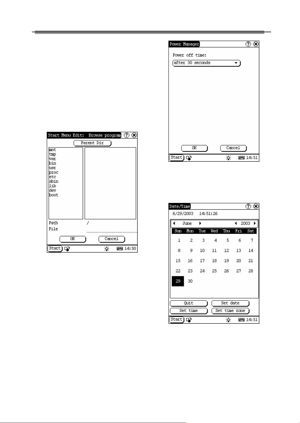
LAUNCH X-431 User’s Manual
on followed by clicking [OK] button.
7) Save the information:
After editing the application, click [OK]
button. The modified information will be
saved in the corresponding file. If you
want to quit the modification, click [Cancel]
button.
Note:
Quit all other applications before saving the
modification.
Figure 4-39
Power Management
In the Power Manager interface, you can see
the condition of memory, and set the standby
time. (See Figure 4-40)
1) In the Control Panel interface, click
‘Power’ icon to open the Power Manager
interface.
2) Click the button to the right of ‘Standby
time’, and select the time or ‘None’ in the
pop-up list.
3) Click [OK] button to save the setting and
close the Power Manager interface.
Figure 4-40
Clock
User can set the time and the time zone of the
system.
Figure 4-41
Set Time:
1) In the Control Panel interface, click ‘Clock’
icon to open the Date/Time interface as
shown in Figure 4-41.
2) In the Date/Time interface, click [Set Time]
button to open the Set Time interface as
shown in Figure 4-42.
3) Click the characters to the right of ‘Day’ to
45
Page 49

LAUNCH X-431 User’s Manual
set AM and PM, the selected one will be
highlighted.
4) Activate Soft Keyboard, and then you can
set ‘Hours’, ‘Minutes’ and ‘Seconds’
directly.
5) Click [OK] button to save and close the
Set Time interface.
Figure 4-42
Set Date:
2) In the Date/Time interface, you can set
date directly.
3) Click [ ] icon to the left of the month or
year to select the previous month or year.
4) Click the [ ] icon to the right of the
month or year to select the next month or
year. (See Figure 4-41)
5) Click the date in the current month. It will
be highlighted when it is selected.
6) Click [Set Time] button to save the setting.
7) Click [Quit] button to exit.
Set Time Zone
1) In the Date/Time interface, click [Set Time
zone] button to open the Set Zone
interface as shown in Figure 4-43.
2) Click Scrolling Bar to turn to next page of
the list, and select your zone. It will be
highlighted when it is selected.
3) Click [OK] button to save and close the
Set Zone interface.
Figure 4-43
After finishing all settings, click [OK] button in
the Date/Time interface to exit and close the
interface.
Contrast
It is for adjusting the contrast of the screen to
make the interface clearer.
1) In the Control Panel interface, click
‘Contrast’ icon to open the Contrast
interface. See Figure 4-44.
2) In the Contrast interface, click the position
you want, and then you can set it.
46
Page 50
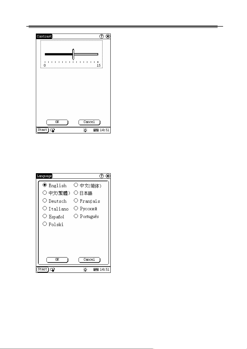
LAUNCH X-431 User’s Manual
Note: Before selecting language, be sure to
quit all applications.
System Information
Calibrate Touch screen
It is for getting the desired accuracy of the
touch screen. Calibrating of touch screen can
be divided into two steps. The first step is to
detect noise automatically. If you click the touch
screen at this step, the noise value would be
affected. After detecting the noise, the system
will come to the calibration step. Then the cross
cursor will be displayed.
Figure 4-44
1) After switching on the machine, follow the
tips to press the hot key. The calibration
interface will be opened.
Language
You can make selection among several
languages for convenient operation of the
system.
2) Click the cross cursor on the screen
accurately, and wait until it changes. Then
one step of calibration is finished.
3) After calibration is finished for all corners,
the system will automatically return to the
start-up main interface.
Note:
♦ Do not click the touch screen before the
cross cursor appears.
♦ In the calibration step, if you fail to click
the cross cursor accurately, the cross
cursor will be displayed on the screen
again and again until the calibration is
finished completely.
Figure 4-45
1) In the Control Panel interface, click
‘Language’ icon to open the Language
interface. See Figure 4-45.
2) Select the language you want to use.
3) Click [OK] button to confirm the selection
and close the language interface and the
Control Panel interface.
User Register
The user’s right can be well protected after
registration.
1) Click [Start] button.
2) Select ‘Information’ in the pop-up menu.
3) Select ‘User’ in the pop-up list to open the
User Information interface. (See Figure
4-46)
4) In the User Information interface, activate
Soft Keyboard, and input the user
information. (See Figure 4-47)
5) Click [OK] button to save the information
and close the User Information interface.
47
Page 51

LAUNCH X-431 User’s Manual
Figure 4-46
Figure 4-47
About
In ‘Information’ list, click ‘About’ to display the
information on system software and hardware,
then click [OK] button to close it. (See Figure
4-48)
Figure 4-48
Shut Down
Click “Shut Down” in the Start menu when you
attempt to turn off the machine.
48
Page 52

LAUNCH X-431 User’s Manual
Answer: There are two possible causes:
FAQ
X431 is a hi-tech product. With the
development of modern automotive industry,
more and more new technology will be adopted
and there may be questions during operation.
Read the user’s manual to get the answer
whenever you have any question, or contact
our Customer Service Center for help.
Here we list some frequently asked questions
and answers relating to X431.
About Update via Internet
Question: “Removable Disk” icon does not
appear in the catalogue of “My computer” after
the CF card reader/writer is connected to the
USB port of computer. Why?
Answer:
Possible cause: there may not be driver for CF
card reader/writer in the computer. The default
driver is with the operating systems like
Windows Me/2000/XP, Mac OS 9.x/Mac OS X
and Linux 2.4.X. However, there is no such
default driver with Windows 98.
Solution: Check if there is the driver for CF
card reader/writer in the computer. If the
computer uses Windows 98 operating system, it
is necessary to install the driver into computer
by using the CD-ROM provided with CF card
reader/writer.
When the CF card reader/writer driver is
installed successfully, a “Removable disk” icon
will appear in the catalogue of “My computer”.
Usually it is listed after original disk drive. For
example, if there were drives A, B, C and D
originally, the removable disk will be “E”. If there
were drives A, B, C, D and E originally, the
removable disk will be “F”. The rest may be
deduced by analogy.
Question: Some downloaded diagnostic
program is not listed in the update tool, what is
the reason?
1. The downloaded diagnostic program is not
put in the same folder as other diagnostic
programs. Please move it to the same folder as
others.
2. The diagnostic program is not fully
downloaded. Please download the program
again.
Question: When the updated software is used
in vehicle diagnosis, some diagnostic program
can not be downloaded successfully from the
CF card. Why?
Answer: possible causes and solutions:
1. The Display Program may have not been
updated. Please update the Display Program.
2. The diagnostic program for the vehicle make
is damaged. Please re-download the diagnostic
program and update.
Question: Why can’t the main unit recognize
the replaced CF card?
Answer: There are two possible causes:
1. The original 32M CF card has not been fully
copied. Please delete the incomplete file and
copy again.
2. The CF card reader/writer is not compatible
with the CF card. Monofunctional CF card
reader/writer is better in such situation.
Question: How to make a new X431 CF card
when the data in old one is lost or damaged?
Answer: In case X431 CF card is damaged
and the program in the card can not be used,
please use the following procedure to make a
new CF card:
1. Log onto the website "www. X431. com".
Enter your username and password to log
in.
Select the SMARTBOX No., and then
download the following programs into your
computer:
1) Necessary programs for making CF card:
49
Page 53

LAUNCH X-431 User’s Manual
l X431 UPDATE TOOLS---- for writing
the program from computer to CF
card when doing X431 update
l DISPLAY PROGRAM---- for
displaying the X431 diagnostic
information and managing the X431
diagnostic programs
l SYSTEM DATA---- system data
used by X431 system
2) Optional programs that can be selected
according to user's demand:
Diagnostic program for various vehicles
2. Install the X431 UPDATE TOOLS into
computer.
3. Format the X431 CF card.
4. Run the X431 UPDATE TOOLS and write
the display program, system data and
diagnostic programs onto CF card.
About Hardware
Question: After X431 downloads the diagnostic
program from the CF card, it prompts “Please
contact your local dealer”. What is the reason?
Answer: It is because the license No. in CF
card does not match the SMARTBOX. It can be
solved in the following way:
1. Download the software that is corresponding
to the SMARTBOX so that the CF card can
match the SMARTBOX.
2. Use the UPDATE TOOL that is provided on
http: // www. X431. com for update. Never use
WINZIP or other decompressing tool for update.
Question: Why does the LCD screen respond
so slowly?
Answer: It is because the ambient temperature
is close to the lower limit of operating
temperature range (0-50℃). In this situation, it
is necessary to warm up the machine for 20
minutes before test.
Question: Power can not be turned on with the
power button on the main unit after the machine
is connected to vehicle diagnostic socket
through cables and connectors. What can I do?
Answer: Check the power pin of vehicle
diagnostic socket with multimeter for power.
The power pin in diagnostic socket varies from
one vehicle to another. Please refer to the
User’s Manual of specific vehicle diagnostic
program to find the power pin. If there is no
power supply from the diagnostic socket,
please get power in other ways, such as from
battery or cigarette lighter.
Question: There is no character on the backlit
screen. What should I do?
Answer: Check if the power is well connected.
Turn off the machine, unplug the power
connector and re-plug it. Turn on the machine
after it has been connected to the power for 1
second.
Question: Printer does not respond or its
printed result is incomplete. What should I do?
Answer: Check if the printer is well connected
with the main unit. Unplug the printer connector
and re-plug it again to check the printed result.
Question: Why can’t the diagnostic program be
downloaded to SMARTBOX?
Answer: Please make sure that the
SMARTBOX is well connected with X431 main
unit.
Question: Why does X431 fail in
communication with ECU?
Answer: Please make sure that the diagnostic
connector and diagnostic program are matching
vehicle make.
Question: The screen keeps blank after
flashing when the machine is turned on. What
should I do?
Answer: Take out the CF card and re-start the
machine to see if there is normal display. If the
display is normal when the CF card is taken out,
50
Page 54

LAUNCH X-431 User’s Manual
the CF card should be replaced. If the screen is
still blank, please contact the local service
engineer.
Question: Why does the system prompt that no
CF card is found when the machine is turned
on?
Answer: The possible cause is that no CF card
is in the machine, or CF card is inserted
improperly or damaged. If it is damaged, it is
necessary to make a new one.
Question: What should I do if I can’t get into
the diagnostic interface during test?
Answer: The possible cause is that no CF card
is in the machine, or CF card is inserted
improperly or damaged. If it is damaged, it is
necessary to make a new one.
Question: Program is not run or screen is
confused after glints. What should I do?
Answer: Unplug the 9-pin connector on the
main unit and re-plug it.
Question: What can I do if the system halts or
fails during self-detection?
Answer: Please make sure that cables and CF
card are well connected.
Question: Why can’t the data be inputted after
Soft Keyboard is activated?
Answer: The position where the cursor lies
can’t be edited. Or you have not activated the
cursor on the input position. Please use the
stylus to click the part to edit. When the cursor
twinkles, you can input the data.
Question: The screen is inactive after the cross
cursor appears on the screen. Why?
Answer: The system is calibrating the touch
screen. The machine will work after the screen
is calibrated. Refer to the section “Calibrate
Touch Screen” in User’s Manual”.
Question: Why does the saved data
disappear?
Answer: There are two possible causes:
1. Your CF card is damaged.
2. You’ve changed language and the data is
related to language. You may find the data after
switching back to the former language.
Question: How to know what applications
(interfaces) are opened.
Answer: Click the active taskbar icon, then the
pop-up list will display the applications
(interfaces) opened.
Question: Why can’t I do operation in current
interface?
Answer: There are two possible causes:
1. Your current interface has exited illegally. In
this situation, you may not see the name of the
application (interface) in the pop-up list when
you click the active taskbar icon.
2. The system is busy, please wait patiently, or
click the active taskbar icon to switch to another
application.
Question: The listed icons of vehicle make
occupy more than one page of screen. I may
have to turn several pages to find a specific
icon of vehicle make. How can it be simplified?
Answer: X431 can test many vehicle makes
and the vehicle makes are still increasing. We
have considered the convenience when
designing the software. The system will count
the clicks and move the icon with more clicks
forward.
About System Setting
Question: The screen is too white and
characters can not be seen. What is the reason
and what should I do?
Answer: It may be caused by improper contrast.
Please refer to the section “Contrast” to adjust
the contrast.
51
Page 55

LAUNCH X-431 User’s Manual
Question: The screen is inactive after the cross
cursor appears on the screen. Why?
Answer: The system is calibrating the touch
screen. The machine will work after the screen
is calibrated. Refer to the section “Calibrate
Touch Screen” in User’s Manual”.
Question: The screen does not respond or
responds wrongly when I click it with stylus.
What should I do?
Answer: It is necessary to calibrate the screen.
Please refer to the section “Calibrate Touch
Screen” in User’s Manual.
Question: The time displayed in the lower right
corner of the screen is incorrect. How to adjust
it?
Answer: It is because the time was set
incorrectly. Please refer to the section “Clock” in
the User’s Manual to set correct time.
About Operation
Question: System halts when reading data
stream. What is the reason?
Answer: It may be caused by a slackened
connector. Please turn off the machine, firmly
connect the connector, and switch on the
machine again.
Question: Why is the screen inactive when the
cross cursor is clicked during screen
calibration?
Answer: You may have touched the screen
when the system is detecting noise before the
cross cursor appears. Please turn off the
machine and then turn on. Calibrate the screen
after the cross cursor appears.
Question: Why is the machine automatically
powered off during standby?
Answer: It is because the machine has been
set for energy saving. Automatic shutdown will
take place if the machine is not operated for a
specified period of time. Refer to the section
“Power management” in User’s Manual to set
the “Power off time” to “None” or select a longer
standby time.
Question: Why can’t the tested result be
printed out?
Answer: There may be no paper in the printer
or the printer is not well connected. Please
mount a roll of new paper. See the section
“Printer Operation” in the User’s Manual.
Question: Why is there no character in the
printed paper?
Answer: The paper is mounted reversely.
Please take out the paper and mount it again.
See the section “Printer Operation” in the
User’s Manual.
Question: The displayed information can not
be seen clearly when the ambient light is not
good. What should I do?
Answer: There is a [ ] icon at the lower right
corner of the screen. Click it to turn on the back
light so as to see the displayed information
clearly. Click the icon again for turning off the
backlight.
Question: Why can’t I input data after
activating Soft Keyboard?
Answer: The position where the cursor lies
can’t be edited. Or you have not activated the
cursor on the input position. Use the stylus to
click the part to edit. When the cursor twinkles,
you can input the data.
Question: What should I do if I am not able to
switch from Active Taskbar to the running
application interface?
Answer: Please close interfaces related to the
application, such as the Help or Detail.
Question: Why does the saved data
disappear?
52
Page 56

LAUNCH X-431 User’s Manual
Answer: There are two possible causes:
1. Your CF card is damaged. It is necessary to
make a new CF card.
2. You’ve changed language and the data is
related to language. You may find the data after
switching back to the former language.
Question: What can I do when the screen is
confused?
Answer: Please quit the current application
(interface), and run it again. If the problem still
exists, please restart the system.
Question: How to know what applications
(interfaces) are opened.
Answer: Click the active taskbar icon, then the
pop-up list will display the applications
(interfaces) opened.
Question: Why can’t I do operation in current
interface?
Answer: There are two possible causes:
1. Your current interface has exited illegally. In
this situation, you may not see the name of the
application (interface) in the pop-up list when
you click the active taskbar icon.
2. The system is busy, please wait patiently, or
click the active taskbar icon to switch to another
application.
Answer: Make sure that the voltage of vehicle
battery, ignition timer and idle speed are in
standard range; the throttle is in the closed
position; and all electric devices, such as A/C,
headlight, stereos etc, are turned off. Refer to
the section “Conditions for Test”.
Question: Some systems can not be
diagnosed. Why?
Answer: The diagnostic socket for the system
on some early vehicle may be separated. Refer
to the vehicle instruction manual.
Question: No trouble code is found. Why?
Answer: It may be caused by the shared circuit.
Find the nearest trouble code and circuit for
analysis.
Question: Why are there too many trouble
codes?
Answer: It may be caused by poor contact or
poor grounding. Make sure that the vehicle
model/year is selected correctly and the vehicle
is equipped with the system.
Questions Related to Vehicle
Question: Why does the screen flickers during
engine starting?
Answer: It is caused by the electromagnetic
interference. No problem with X431.
Question: Why is operation interrupted during
diagnosis?
Answer: It may be caused by electromagnetic
interference or incorrect connection of
connector.
Question: Why is there no response from
vehicle ECU at communication?
53
Page 57

LAUNCH X-431 User’s Manual
About ECU
In the last two decades, we have seen more
and more extensive application of IT and
electronic technologies in modern vehicles.
Many vehicle control systems, typically EFI
(Electronic Fuel Injection), ABS (Anti-block
Braking System), SRS (Air Bag), TC (Traction
Control), AT (Automatic Transmission), etc., are
computerized. Computerization makes the
control precisely, quickly, effectively and safely.
Consequently, a significant progress in vehicle
driveability, fuel economy, power performance,
comfortability, emissions, safety and so on has
been made.
Composition and Working
Principle of ComputerControl System
The Computer Control System consists of the
on-board computer, and several related control
devices (sensors, switches, and actuators).
Most on-board computers are located inside the
vehicle behind the dashboard, under the
passenger’s or driver’s seat, or behind the right
kick panel. Some manufacturers may still
position it in the engine compartment. The
sensors, switches, and actuators are devices
such as oxygen sensors, coolant temperature
sensors, throttle position sensors, fuel injectors,
etc., that are located throughout the engine,
and are connected by electrical wiring to the
on-board computer. As an example, the
diagram of engine control system is shown in
Figure 6-01.
Sensor
It is a device that converts non-electric variable
into electric signal. More than 50 types of
sensor are used in modern vehicles, most of
which are found in powertrain, chassis control
systems, body control system, safety system,
etc.
According to the physical variables controlled,
sensors are sorted into following types:
temperature sensor, pressure sensor, air flow
sensor, position/angular sensor, gas
concentration sensor, rotary speed sensor,
acceleration sensor, vibration sensor, light
sensor, distance sensor, electrical current
sensor, angular speed sensor, shaft sensor,
liquid level sensor, etc.
The commonly-used sensors in corresponding
control systems of vehicle are:
1) In engine management system: intake air
pressure (or air flow), air/fuel ratio,
crankshaft position, knock, RPM, intake air
temperature, coolant temperature and O2
sensors.
2) In transmission system: vehicle speed,
throttle position, RPM, A/T output shaft
speed, toque, oil pressure/temperature,
shift position sensors.
Figure 6-01
54
Page 58
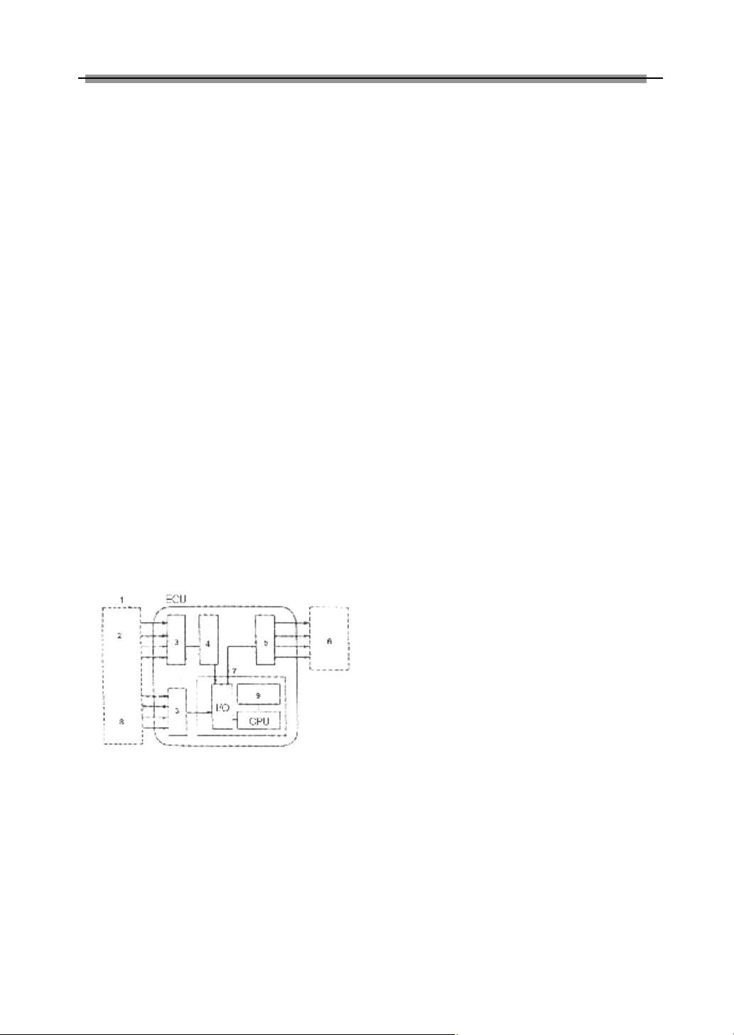
LAUNCH X-431 User’s Manual
3) In braking system: vehicle speed, wheel
speed, deceleration, sliding rate, braking
pedal force, braking pedal position sensors,
etc.
4) In steering control system: steering, vehicle
acceleration, vehicle speed sensors, etc.
5) In suspension system: vehicle speed,
vehicle height, steering angle, throttle
position, braking force sensors, etc.
6) In A/C system: external temperature,
internal temperature, sunshine, coolant
temperature, refrigerant pressure and
humidity sensors, etc.
7) In instrument, alarm and diagnosis systems:
remaining fuel, coolant temperature, oil
pressure, oil status, intake air pressure,
windshield washer fluid level, battery liquid
level, door lock, braking fluid level sensors.
ECU
into electrical parameter.
2) A/D converter: it converts the analogue
signal from the sensor into digital signal.
Then the digital signal can get into SMC.
3) SMC: it consists of I/O interface, CPU,
RAM/ROM, etc. The received digital signal
is computed here with the pre-programmed
parameters from ROM. The computed
result is transmitted through I/O interface to
the output circuit, and then to the
corresponding actuators.
The data in ROM is written by manufacturer
and will not be lost when power is off.
However, the data in RAM will be lost when
power is off.
4) Output circuit: it is to amplify the signal from
SMC. The weak current from SMC is not
able to activate the actuator. So it has to be
amplified.
The electronic control unit is composed of input
circuit, A/D converter, SMC, output circuit, etc.
See Figure 6-02.
Figure 6-02
1- Sensor 4- A/D converter 7- SMC
2- Analog signal 5- output circuit 8- Digital signal
3- Input circuit 6- Actuator 9- ROM/RAM
1) Input circuit: digital signal from sensor will
enter the CPU directly. However, the
analogue signal will be treated in the A/D
converter before getting into CPU. The
input circuit filters out the noise, converts
sine wave into rectangular wave and then
55
Actuator
Actuator is to convert the electrical signal into
force or displacement. The popular actuators
are listed below:
1) Solenoid valve: This actuator is to convert
electrical signal into linear movement. Two
types of solenoid valves are used in the
vehicle. One is directly driven with linkage,
e.g. the magnetic switch of starter motor.
The other is for controlling pressure and
flow by transferring the movement to
relevant valves. For example, in engine
intake air control, electronically controlled
automatic transmission, suspension control,
etc.
2) Motor: DC motor is the most popular
actuator used in automobile. It can be
divided into two types according to its use.
One is rotated by power, e.g. windshield
wiper, seat adjuster, etc. The other is used
in servo mechanism. In this situation,
external force makes the rotor rotate
around the stator, e.g. the servo motor for
Page 59

LAUNCH X-431 User’s Manual
damper.
Besides the two types listed above, there are
other types, such as relay, electronic switch,
etc.
Self-diagnosis of Electronic
Control System
All modern cars are controlled by an Electronic
Control Unit (ECU). The main purpose of the
electronic control system is to provide
maximum engine performance with the least
amount of air pollution and the best fuel
efficiency possible. However, the complexity of
the system may increase the difficulty for its
troubleshooting. The function of self-diagnosis
is for solving such problem with electronic
control system.
Working Principle of Self-diagnosis
The composition of self-diagnosis system is
similar to electronic control system. The basic
component is electronic control unit. The main
purpose of self-diagnosis system is to diagnose
the sensors, actuators, circuits and ECU in
vehicle.
The computer assigns a numeric code for each
specific problem that it detects, and stores
these codes in its memory for later retrieval,
and turns on the fault indicator on the dash
panel to warn the driver. The problem detected
may be: inputted/outputted signal exceeds the
specified range, or some circuit is
short-circuited or open.
Now let’s take gasoline injection control system
as an example to describe the working principle
of the self-diagnosis system. When problem
occurs, the process of diagnosis and treatment
will be as follows:
1) For sensor
If the output signal from the sensor is out of the
specified range of voltage when engine is
running, it will be deemed as fault. For example,
the normal output voltage from coolant
temperature sensor should be in the range of
0.3-0.4V. If not, the situation will be deemed as
fault and fault code will be stored in memory.
Self-diagnosis system can detect damaged
sensor, or short/open circuit, but it can not
appraise the performance of sensor. Occasional
occurrence of abnormal signal will not be
deemed as fault immediately. For not being
interrupted by the sensor fault, the engine will
be controlled by the pre-stored normal coolant
temperature (e.g. 80℃) from the self-diagnosis
system.
2) For actuator
When the engine is running, ECU sends
commands to actuators according to the
practical situation. If the actuator can not work
normally, the monitoring circuit will transmit the
message to the ECU. ECU can make the
message displayed and take measures to
ensure the safe running of engine. For example,
when the power tube in engine ignition system
is out of order, the ignition monitoring circuit
sends feedback to the ECU. ECU emits
warning signal and sends commands to
actuator for stopping injection so as to prevent
the unburnt mixture from damaging the catalytic
converter of exhaust system.
3) For ECU
There is no monitoring circuit, but a monitoring
clock in the ECU for resetting ECU regularly. If
ECU is out of order, its program will not be run
and the clock will not reset the ECU so that
overflow may occur. This situation is deemed as
fault for displaying.
For preventing unexpected stopping of vehicle
caused by problem with ECU, there is a backup
circuit in ECU. When the backup circuit
receives the signal of abnormality from the
monitoring circuit, a spare control program will
be started for keeping the engine running as
pre-programmed.
Readout of Fault Code in Automotive
Self-diagnosis System
The fault in vehicle electronic system is stored
in KAM of ECU as fault code. The fault code
can be read out by the on board diagnostic
56
Page 60

LAUNCH X-431 User’s Manual
system or external scan tool.
The on board diagnostic system in different
vehicle may indicate the fault in different way. In
general, the following ways are popular:
1) Blinking of fault indicators on the instrument
panel
2) Swing of multimeter index
3) Blinking of red/green LED on ECU
4) Shown by a special device
The more intuitionistic way for showing the fault
is by external scan tool.
The diagnostic system of modern cars is
equipped with diagnostic socket or DLC (data
link connector). Fault code in vehicle ECU can
be read out by connecting a scan tool to the
diagnostic socket. In early time, each vehicle
system had its own type of diagnostic socket.
Since 1996, SAE has specified a uniform
system called OBDII on board diagnostic
system. Each vehicle that is made in
accordance with the system may have the
same diagnostic socket, same definition of pin
and same description of fault code. The control
units of every system are connected to bus, so
only one diagnostic socket is needed for
readout of fault code. OBD provides the
possibility of reading data stream and
displaying working status of switches and
actuators. Moreover, external scan tool can
send commands to activate the actuators.
X-431 is such an external scan tool for vehicle
diagnosis. It not only has the diagnostic function
like reading fault code, reading data stream,
actuation test, displaying sensor waveform,
coding control unit, etc., but also has PDA
function.
Basic Knowledge of ECU
Composition of Vehicle ECU
Vehicle ECU consists of ALU, CPU, power
source and memory.
1. ALU
It converts the electronic signal from each
sensor into digital signal needed by CPU.
2. CPU
The digital signal is transferred to CPU for
computation and logical operation so that
correct air/fuel mixture can be obtained. CPU
can also compute ignition timing and idle speed,
and control exhaust, fuel and diagnostic
systems.
3. Power source
The reference output signal (5V) of ECU and
the 12V voltage for control module are from
vehicle battery. Memory is also dependent on
the power supplied by the battery.
4. Memory
ECU contains three types of memory: ROM,
RAM and PROM (or EEPROM).
1) ROM
ROM stores the programming information
that can only be read by ECU. The program
in ROM is not editable. Power cut will not
damage the data in ROM.
2) RAM
It is for temporarily storing the inputted data,
fault code and computed result. Power cut
will make all information in RAM erased.
3) PROM
Its program is made by manufacturer to suit
the application of transmission, engine,
exhaust control, driveability, rear axle ratio,
etc. PROM is can be detached from ECU
and power cut will not damage the data in
it.
4) EEPROM
Its function is similar to PROM. The
difference between EEPROM and PROM is
that EEPROM can be re-programmed by
manufacturer with a special device.
Precautions Related to ECU
The circuit inside the ECU is very accurate and
may be easily damaged by overvoltage, static
electricity and/or magnetic fields. Pay more
attention when diagnosing the devices that is
57
Page 61

LAUNCH X-431 User’s Manual
connected to ECU because most ECU’s are
operated under low voltage (about 5V).
Whenever you work in the vicinity of ECU or
engine control system, please obey the
following precautions:
1. Never damage the lead or connector.
Prevent them from being grounded or
contacting with an unexpected power source.
2. Never use the electrical test tool that is
powered by 6V battery or over. Strong
current may cause the element in ECU
broken or shorted. For checking the engine
control circuit, only the multimeter with large
internal impedance (over 10MΩ) can be
used.
3. Never try to disassemble or repair ECU if
there are not necessary tools and
information. Any mistake may damage the
component or increase the difficulty for
service station.
4. The spark plug wire must be at least 25.4mm
from any sensor circuit or control circuit.
Some unexpected fault in ECU circuit is
caused by magnetic fields that transmit
wrong signal to ECU. High tension wire or
transformer may interfere with ECU, but the
most common cause for such problem is that
the spark plug is too close to ECU harness.
5. Be careful when moving ECU or working
around ECU. Remember that static electricity
may cause strong electrical shock and
damage ECU.
58
Page 62

LAUNCH X-431 User’s Manual
Appendix 1: about VIN
VIN is the abbreviation of Vehicle Identification
Numbers.
A car’s vehicle identification number (VIN) is the
identifying code for your SPECIFIC automobile.
It is your car's fingerprint.
It sets your vehicles apart from the millions of
vehicles out there. Recently the VIN is reflected
by 17 digit characters. It displays a car’s
uniqueness and manufacturer and provides a
method to trace your car from the factory to the
junk yard.
Each character or digit has a particular
purpose. They are as follows:
l First vehicle identification number digit
identifies the country from which the vehicle
was manufactured. For example, U.S.A.(1
or 4), Canada (2), Mexico (3), Japan (J),
Korea (K), England (S), Germany (W), Italy
(Z).
l Second vehicle identification number digit
specifies the manufacturer. Audi (A), BMW
(B), Buick (4), Cadillac (6), Chevrolet (1),
Chrysler (C), Dodge (B), Ford (F), GM
Canada (7), General Motors (G), Honda (H),
Jaguar (A), Lincoln (L), Mercedes Benz (D),
Mercury (M), Nissan (N), Oldsmobile (3),
Pontiac (2 or 5), Plymouth (P), Saturn (8),
Toyota (T), Volvo (V).
l Third vehicle identification number digit
indicates the vehicle type or manufacturing
division.
l Fourth through eighth vehicle identification
number digit reveals the vehicle features
such as body style, engine type, model,
series, etc.
l The ninth vehicle identification number digit
is a VIN accuracy check digit, verifying the
previous VIN numbers. This is how the
check digit works:
♦ STEP 1
Assign to each number in the VIN its
actual mathematical value and assign to
each letter the value specified for it in the
following chart:
ASSIGNED VALUES:
A=1 G=7 P=7 X=7
B=2 H=8 R=9 Y=8
C=3 J=1 S=2 Z=9
D=4 K=2 T=3
E=5 M=3 U=4
F=6 N=4 V=5
♦ STEP 2
Multiply the assigned value for each
character in the VIN by the position
weight factor specified in the following
chart:
VIN POSITION AND WEIGHT FACTOR:
1st = 8 10th = 9
2nd = 7 11th = 8
3rd = 6 12th = 7
4th = 5 13th = 6
5th = 4 14th = 5
6th = 3 15th = 4
7th = 2 16th = 3
8th = 10 17th = 2
9th = check digit
♦ STEP 3
Add the products from steps 1 and 2 and
divide the total by 11.
♦ STEP 4
The numerical remainder is the check
digit which would appear in the 9th
position in the VIN. If the remainder is 10,
then the letter "X" is used for the check
digit.
l Tenth vehicle identification number digit
tells the model year. 1988 (J), 1989 (K),
1990 (L), 1991 (M), 1992 (N), 1993 (P),
1994 (R), 1995 (S), 1996 (T), 199 7(V),
1998 (W), 1999 (X), 2000 (Y)------2001(1),
2002 (2), 2003 (3)
59
Page 63

LAUNCH X-431 User’s Manual
l Eleventh vehicle identification number digit
reveals the assembly plant for the vehicle.
l The twelfth to seventeenth vehicle
identification number digits indicate the
sequence of the vehicle for production as it
rolled of the manufacturers’ assembly line.
Your VIN can be used to track recalls,
registrations, warranty claims, thefts and
insurance coverage.
Common locations of the vehicle identification
number (VIN) vary but the following are places
to look:
l Firewall of the vehicle
l Left hand inner wheel arch
l Steering column
l Radiator Support Bracket
l Dash by windshield
l Drivers door or post on passenger side
l Guarantee & Maintenance Book *Vehicle
documents
l Machined Pad on front of engine
l Component parts as listed above -eg-
engine, frame, etc.
Later model years - most common area's of
VIN:
l Left instrumentation/dash panel by window
l Drivers door or post
l Firewall
60
Page 64

LAUNCH X-431 User’s Manual
Appendix II: Block and Parameter Definition of
Volkswagen Vehicle
Passat B5 Engine Data Stream Block Table
Display Definition
Block 00
1. 170...204
2. 17…44
3. 82...99
4. 142...206
5. 0...12
6. 123...133
7. 120...136
8. 77...179
9. 115...141
10. 117...138
Block 01
1. 820...900rpm
2. 1.00...2.50ms
3. 0…5∠0
4. 5.25...4.250VOT
Block 02
1. 820…900 rpm
2. 1.00…2.50ms
3. 2.00…5.00ms
4. 2.0…4.0g/s
Block 03
1. 820…900rpm
2. 10…14.5V
3. 80…105℃
4. 90℃
Block 04
1. 0…5∠0
2. –1.70...1.70g/s
3. –1.70...1.70g/s
4.
1- coolant temperature
2- engine load
3- engine speed
4- ECM voltage supply
5- throttle angle
6- idle regulator
7- idle stable adaption value
8- O2 excessive regulator
9- mixture adaption value
10- mixture adaption value
1- engine speed
2- engine load (injection duration per revolution)
3- throttle angle
4- ignition angle
1- engine speed
2- engine load (injection duration per revolution)
3- engine injection duration per cycle
4- intake air volume
1- engine speed (idle speed)
2- ECM voltage supply
3- coolant temperature
4- intake air temperature
1- throttle angle(acceleration pedal depressed to the
end75...95 0)∠
2- idle air mass adaption value (N gear)
3- idle air mass adaption value (drive gear)
4-working condition
Idling idle
Teillast part load
61
Page 65

LAUNCH X-431 User’s Manual
Vollast full load
Schub rich
Anreicherung O/D
Block 05
1. 820…900rpm
2. 860rpm
3. -10.0...10.0%
4. 2.0...4.0g/s
Block 06
1. 0...2550
2. -10.0...10.0%
3. -10.0...10.0%
4. -10…+45∠0
Block 07
1. -10.0...10.0%
2. 0...1.100V
3. 0...99%
4. 0.30...1.10
Block 08
1. 2.00...5.00ms
2. -10.0...10.0%
3. -8.0...8.0%
4.
1- idle speed (idle speed)
2- idle speed (rated, M/T)
3- idle intake air regulation (idle regulator)
4- intake air volume
1- engine speed
2- idle intake air regulation ( idle regulator)
3-λregulator
4- ignition angle
1-λ regulator control
2-λ sensor voltage (higher than 0.45V denote rich,
less than 0.45V denote lean)
3- canister solenoid valve 1 duty ratio
4-λtrim with EVAP
1- injection time (per cycle)
2- idle λ adaption value(add)
3- part load λ adaption (multiply)
4- EVAP mode
TE active: canister solenoid active
TE not active: canister solenoid inactive
λ adaption: canister solenoid inactive, λ regulator
active
Block 09
1. 820...900rpm
2. -10.0...10.0%
3. 0...1.100V
4. -10.0...10.0%
Block 10
1. 0.00...0.30
2. -3...32
3. 0.30...1.20
4. 0...99%
Block 11
1. 820...920rpm
2. 2.00...5.00ms
3. 0 km/h
4. 0.5...1.50 l/h
1- engine speed (idle rpm)
2-λregulator
3-λsensor voltage
4- idleλadaption value (add)
1- canister solenoid valve 1 duty ratio
2-λmodification when the EVAP is active
3- canister charge rate
4- EVAP purge rate
1- engine speed (idle rpm)
2- engine load
3- vehicle speed
4- fuel consumption
62
Page 66

LAUNCH X-431 User’s Manual
Block 14
1. 820...920rpm
2. 1.00...2.50ms
3. 0...15.0 0KW
4. 0...15.0 0KW
Block 15
1. 820...920rpm
2. 1.00...2.50ms
3. 0...15.0 0KW
4. 0...15.0 0KW
Block 16
1. 0.300...1.400V
2. 0.300...1.400V
3. 0.300...1.400V
4. 0.300...1.400V
Block 18
1. 820...920rpm
2. 1.00...2.50ms
3.
4. -30.0...25.0%
Block 19
1. 820...920rpm
2. 1.00...2.50ms
3.
4. 12∠0
Block 20
1. 820...920rpm
2.
3.
4.
Block 21
1. 820...920rpm
2. 1.00...2.50ms
3. 80…105℃
4.
Block 23
1.
2. 72.0...95.0%
1- engine speed (idle rpm)
2- engine load
3- ignition delay of cylinder 1 due to the knock control
4- ignition delay of cylinder 2 due to the knock control
1- engine speed
2- engine load
3- ignition delay of cylinder 3 due to the knock control
4- ignition delay of cylinder 4 due to the knock control
1- cylinder 1 knock sensor signal voltage
2- cylinder 2 knock sensor signal voltage
3- cylinder 3 knock sensor signal voltage
4- cylinder 4 knock sensor signal voltage
1- engine speed (idle rpm)
2- engine load (without altitude regulation)
3- engine load, throttle angle
4- altitude regulation factor
1- engine speed (idle rpm)
2- engine load
3- working condition
×1×=without ignition delay, ×0×=with ignition delay
4- ignition angle
1- engine speed (idle rpm)
2- shift signal (P/N, 2, 3, 4, R, D)
3- AC mode
4- compressor mode on/off
1- engine speed (idle rpm)
2- engine load
3- coolant temperature
4-λmodification mode off/on
1-adption requirement the first digit:
1=adaption normally finished, 0=adaption required
the third to sixth digit:
1=adaption not finished and abnormal, 0=adaption
63
Page 67

LAUNCH X-431 User’s Manual
3. 67.0...83.0%
4. 18.0...54.0%
finished, normal
the second and seventh digit: not use
2- minimal stop position of throttle regulator
3- urgency operation stop position of throttle regulator
4- maximal stop position of throttle regulator
Block 24
1. 0...6800/mm
2. 0...10.00ms
3. -20...40∠0
4. 0...72.00KW
Block 25
1.
2. -30...300KW
3.
4. -3...210KW
Block 26
1. 0...6800/mm
2. 0...10.00ms
3.
4. -3...210KW
Block 95
1. 820...920rpm
2. 1.00...2.50ms
3. 12∠0
4. 80…105℃
Block 98
1. 0.5...4.9V
2. 0.5...4.9V
3.
4.
Block 99
1. 820...920rpm
2. 80…105℃
3. -10...10%
4.
1- engine speed
2- engine load
3- ignition angle
4- cylinder 1...4 ignition retard angle
1- engine working condition
2- regulation error of Hall sensor
3- working condition (intake air manifold switch
over/camshaft regulation)(second digit by count
down 1=long intake air path, last digit denote
camshaft regulation (1=advance)
4- enable the camshaft regulation
1- engine speed
2- engine load
3- working condition (intake air manifold switch
over/camshaft regulation)
4- enable the camshaft regulation
1- engine speed (idle rpm)
2- engine load
3- ignition angle
4- coolant temperature
1- throttle potentiometer voltage (G69)
2- throttle regulator sensor voltage (G127)
3- engine mode: idle/part load
4- regulation mode:
adapting
adaption finished
adaption error
1- engine speed
2- coolant temperature
3-λ regulation
4-λcontrol mode: off/on
64
Page 68

LAUNCH X-431 User’s Manual
Passat B5 AT System Data Stream Block Table
Display Definition
001
1.
2.
3.
4.
002
1.
2.
3.
4.
003
1.
2.
3.
4.
004
1.
2.
3.
4.
1- shift position (P/R/N/D/3/2/1)
2- throttle potentiometer voltage (idle 156...0.8V,
throttle wide open 3.5...4.680V)
3- acceleration pedal (idle 0...1%, wide open throttle
99...100%)
4- wide open throttle position (the first digit: 1=pedal
depressed, 2=pedal released. The second digit:
1=TCS enabled, 0=TCS disabled. The third digit:
not use. The fourth digit: 1=kickdown switch
enabled, 0=kickdown switch disabled. The fifth
digit: for multifunction switch F125, R, N, D, 3, 2 is
1;P, 1 is 0). The sixth digit: for multifunction switch
F125, P, R, 2, 1 is 1; N, D, 3 is 0. The seventh
digit: for multifunction switch F125, R, N, D, P is 1;
3, 2, 1 is 0. The eighth digit: for multifunction
switch F125, R, N, P is 1; N, D, 3, 2, 1 is 0.
1- solenoid valve 6-N93 rating current (neutral, wide
open throttle 0.0A, idle maximal 1.1A)
2- solenoid valve 6-N93 rating current (neutral, wide
open throttle 0.0A, idle maximal 1.1A)
3- battery voltage (10.8...16)
4- VSS-G68 voltage (stop, .20...2.52V)
1- vehicle speed
2- engine speed
3- gear (neutral=0, reverse=R, gear 1 hydraulic=1H,
gear 1 mechanical =1M, gear 2 hydraulic =2H,
gear 2 mechanical=2M, gear 3 hydraulic =3H, gear
3 mechanical=3M, gear 4 hydraulic =4H, gear 4
mechanical =4M,)
4- acceleration pedal (idle 0...1%, wide open throttle
99...100%)
1- solenoid (solenoid 1-N88=1, solenoid 2-N89=2,
solenoid 3-N90=3, solenoid 4-N91=4, solenoid
5-N92=5, solenoid 7- N94=6.)
Shift position:
P=1010000;
R=0010000;
N=1010000;
D, 3, 2, 1(1H, 1M)=0010000;
D, 3, 2 (2H, 2M)=0110000;
D, 3 (3H, 3M)=0000001;
D (4H, 4M)=1100001.)
2- gear (same as block 003)
3- gear (P/R/N/D/3/2/1)
4- vehicle speed
65
Page 69

LAUNCH X-431 User’s Manual
005
1.
2.
3.
4.
006
007
1.
2.
3.
4.
008 May be ignored
1- ATF temperature
2- shift output (the first and second digit: ignition
timing regulation ON=1, OFF=0; the third digit:
shift lever lockup solenoid -N110 ON=1, OFF=0;
the fourth digit: kickdown solenoid ON=1, OFF=0;
the fifth digit: CCS ON=1, OFF=0; the sixth digit:
AC ON=1, OFF=0; the seventh digit: P/N signal, P,
N=1, R=0, D, 3, 2, 1=1/0.)
3- gear (same as 003)
4- engine speed
May be ignored
1- gear (same as block 003, “+” or “-” depend on
display area 2)
2- lockup clutch slip
3- engine speed
4- acceleration pedal (same as block 001)
Passat B5 ABS Data Stream Block Table
Block Definition
001
1
2
3
4
002
1
2
3
4
003
1
2
3
4
004
1
2
3
4
1- FL rpm sensor wheel speed
2- FR rpm sensor wheel speed
3- RL rpm sensor wheel speed
4- RR rpm sensor wheel speed
1- brake light switch (1: brake pedal depressed=0,
released=1)
2- pump generator voltage (1: with voltage,
abnormal; 0: without voltage, normal)
3- solenoid relay (1: enabled; 0: disabled)
4- not use
1- engine speed (with ASR)
2- engine torque (with ASR)
(0% engine at thrust stage, 20%...30% engine
idle, 100% maximal engine torque)
3- ASR button (with ASR) (1: button pressed; 0:
button not pressed)
4- not use
1- stop time
2- EDS disconnected by too high braking
temperature (0: EDS does not disconnect during
20 times ignition; 1: EDS disconnect during 20
times ignition)
3- EDS/ASR disconnect (0: EDS/ASR normal; 1:
EDS/ASR abnormal)
4- not use
66
Page 70

LAUNCH X-431 User’s Manual
Jetta Engine System Data Stream Block Table
Display Definition
00
1. 170...210
2. 26...50
3. 80...88
4. 176...212
5. 4...12
6. 118...138
7. 112...114
8. 78...178
9. 2242...255bzw
(or) 0…13
10. 118...138
01
1. 800...880 rpm
2. 1.3…2.5ms
3. 2…5∠0
4. 6…120VOT
02
1. 800…880 rpm
2. 1.3…2.5ms
3. 2.0…5.0ms
4. 2.0…5.0g/s
03
1. 800…880rpm
2. 12…15V
3. 80…110℃
4. ... ℃
04
1. 2…5∠0
2. -1.7…+1.7g/s
3. 0.00g/s
4. idle
05
1. 800…880rpm
2. 840rpm
3. -10…+10%
4. 2.0…5.0 g/s
1- coolant temperature (about 80…110)℃
2- engine load (about 1.3...2.5ms)
3- engine speed (about 800...880rpm)
4- battery voltage (about12…14.5V)
5- throttle angle (about 2…50)∠
6- idle air flow regulation (idle regulator) (about
-2.5...+2.5kg/h)
7- idle air flow adaption (about -4...+4kg/h)
8-λ regulation (about-10...+10%)
9-λ regulation adaption (add) (about -0.64...+0.64ms)
10-λ regulation adaption (subtract) (about - 8...+8%)
1- idle rpm changes one time each 40 steps
2- engine load
3- throttle angle
fuel pedal fully depressed: 80…90∠0
when any throttle fault is detected: 35∠0
4- ignition angle
1- idle speed changes one time each 40 steps
2- theoretic fuel injection time per revolution of the crankshaft
3- the calibrated injection time of each working cycle
4- intake air volume
1- engine speed changes one time each 40 steps
2- battery voltage
3- coolant temperature
4- intake air temperature
1- throttle angle
2- idle air flow adaption
3- always display ”0” for M/T
4- working mode (idle, part load, full load, acceleration, O/D
cut off)
1- engine speed (practical) changes one time each 10 steps:
maximal 2550 rpm.
2- engine speed (set) changes one time each 10 steps
3- idle regulator
4- air flow
67
Page 71

LAUNCH X-431 User’s Manual
06
1. 800…880rpm
2. -10…+10%
3. -10…+10%
4. 6…120VOT
07
1. -10…+10%
2. 0…1V
3. 0…99%
4. 0.3…1.1
08
1. 2.0…5.0ms
2. -10…+10%
3. -8…+8%
4. TE active or
TE inactive
09
1. rpm
2. -10…+10%
3. 0…1.0V
4. -10…+10%
10
1. 0…99%
2. 0.3…1.2
3. -3…+32
4. 0.00…0.30
11
1. 800…880rpm
2. 1.3…2.5ms
3. 0km/h
4. 0.5…1.5 l/h
13
1. 0…150kw
2. 0…150kw
3. 0…150kw
4. 0…150kw
14
1. rpm
2. ms
3. 0…150kw
4. 0…150kw
1- idle speed changes one time each 10 steps
2- idle regulator
3-λ--regulator
4- ignition angle
1-λ regulator
2-λ sensor voltage
3- canister N80 solenoid valve 1 duty ratio: 0= N80 closed,
99= N80 full open
4-λ calibration coefficient of EVAP
1- injection time
2-λ adaption at idle (add)
3-λ adaption at full load (subtract)
4-”TE active” denote the canister solenoid valve 1 on and off
according to the time (6 to 16 minutes).”TE inactive”
denote the canister solenoid valve 1 always closed (1
minute)
1- engine speed changes one time each 10 steps
2-λ—regulator
3-λ sensor voltage
4- idle λ adaption (add)
1- canister (AKF) solenoid duty ratio
2- EVAPλcalibration coefficient
3- canister charging grade, -3 denote no fuel smoke in
canister; +32 denote the canister is full of fuel smoke
4- canister filter purging grade (AKF) : 000 = AKF input; 0.30
=30% of intake air comes from AKF
1- engine speed changes one time each 40 steps
2- engine load
3- vehicle speed
4- fuel consumption: the all displayed values are applicable
to the idle mode without extra load (AC, engine, power
steering).
1- reduce ignition angle of cylinder 1 by knock regulation
2- reduce ignition angle of cylinder 2 by knock regulation
3- reduce ignition angle of cylinder 3 by knock regulation
4- reduce ignition angle of cylinder 4 by knock regulation
1- engine speed changes one time each 40 steps
2- engine load (injection time per revolution)
3- ignition angle reduction of cylinder 1 by knock regulation
4- ignition angle reduction of cylinder 2 by knock regulation
68
Page 72

LAUNCH X-431 User’s Manual
15
1. rpm
2. ms
3. 0…150kw
4. 0…150kw
16
1. 0.4…2.0V
2. 0.4…2.0V
3. 0.4…2.0V
4. 0.4…2.0V
18
1. 800…880rpm
2. 1.3…2.5ms
3. …ms
4. -50…+25%
20
1. 800…880rpm
2. 00000100EIN
00000000AUS
3. A/C-high
A/C-low
4. Kompr.EIN
Kompr.Aus
21
1. rpm
2. ms
3. ℃
4. λ regulation off
λ regulation on
23
1. 01000000
2. 73…97%
3. 54…85%
4. 6…43%
1- engine speed changes one time each 40 steps
2- engine load (injection time each revolution)
3- ignition angle reduction of cylinder 3 by knock regulation
4- ignition angle reduction of cylinder 4 by knock regulation
1- knock sensor signal of Cyl 1
2- knock sensor signal of Cyl 2
3- knock sensor signal of Cyl 3
4- knock sensor signal of Cyl 4
1- engine speed changes one time each 40 steps
2- air flow meter engine load
3- throttle angle engine load
4- altitude calibration coefficient
1- engine speed changes each 40 steps
2- low octane number switch (if the fuel is poor, screen
display as below. 00000100EIN (open))
3- AC
High=large AC power
Low=small AC power
4- AC compressor on/off
always display “Kompr.Aus” for vehicles without AC
1- engine speed changes each 40 steps
2- engine load
3- coolant temperature
4-λregulation off/on
1- adaption requirement
1= not use
2= throttle regulator potentiometer adaption minimal
estimate value
“0”=adapted, adaption normal,
“1”=adaption not performed, adaption abnormal
3= throttle regulator potentiometer adaption maximal
compute value
”0”=adaption performed, normal; “1”=adaption not
performed, abnormal
4= throttle potentiometer G69 adaption minimal compute
value “0”=adaption performed, normal; “1”=adaption
not performed, abnormal
5= throttle potentiometer G69 adaption maximal compute
value”0”=adaption performed, normal; “1”=adaption not
performed, abnormal
6=not use
69
Page 73

LAUNCH X-431 User’s Manual
7= throttle potentiometer G69 compare with the throttle
regulator potentiometer, “0”=must compare, “1”=
adaption not performed, abnormal;
8=not use
2- throttle regulator V60 minimal compute value
3- throttle regulator V60 emergency compute value
4- throttle regulator V60 maximal compute value
98
1. 0…5V
2. 0…5V
3. idle
part load
4. ADP active
ADP normal
ADP abnormal
99
1. rpm
2. ℃
3. -10…+10%
4. λ regulation -off
λ regulation -on
1- throttle potentiometer voltage
2- idle regulator potentiometer voltage
3- mode
4- adaption mode
ADP=throttle control unit adaption
1- engine speed
2- coolant temperature
3-λregulator
4-λregulation off/on
System basic setting function: λ regulation off.
Read data stream function: λ regulation on
Golf Engine System Data Stream Block Table
Display Definition
Block 00
1, 2, 3, 4, 5, 6, 7, 8, 9, 10
Block 01
1. about 800 rpm
2. 81...111℃
3. 0…1.0V
4. XXXX XXXX
Block 02
1. about 800 rpm
2.
3. 81...111℃
4. entiroment temperature
Block 03
1. about 800 rpm
2.
3.
4.
Block 04
Used by manufacturer
1- engine speed
2- coolant temperature
3- O2 sensor voltage
4- engine mode
1- engine speed
2- injection pulse width
3- battery voltage
4- intake air temperature
1- engine speed
2- engine load
3- throttle angle
4- ignition timing
70
Page 74

LAUNCH X-431 User’s Manual
1. abou 800 rpm
2.
3. km/h
4. XXXX XXXX
Block 05
1. about 800 rpm
2.
3.
4.
1- engine speed
2- engine load signal
3- speed signal
4- engine mode
1- engine speed
2- engine load
3- mixture calibrate
4- mixture adaption value
Audi 200 Engine System Data Stream Block Table
Display Definition
Block 00
1, 2, 3, 4, 5, 6, 7, 8, 9, 10
Block 01
1. 80...820rpm
2. 29...59%
3. not use
4. 18-75steps
Block 02
1. 0...85%
2. not use
3. 81...111℃
4. environment temperature
Block 03
1. 0.75...1.25
2. not use
3. 0.75...1.25
4. not use
Block 04
1. not use
2. not use
3. 0.75...1.25
4. 0.75...1.25
Block 05
1.680...820 rpm
Used by manufacturer
1- engine speed
2- intake manifold pressure
3- computed ignition angle
4- N71 steps
1- throttle opening
2- intake air manifold pressure
3- coolant temperature
4-intake air temperature
1-λ-control current adaption value (cylinder 1-3)
0=λ control adaption active (AKF off)
1= engine temperature too low
4= idle rpm too low
5= idle rpm too high
6=λ sensor inactive
7=λ control system inactive
10=the rating adaption value not obtained
11=ignition angle retarded
12=ignition angle advanced
16=λ control system inactive
(AKF active)
2-λ-control current adaption value (cylinder 4-6)
3-λ-control (cylinder 1-3)
4-λ-control (cylinder 4-6)
1-λ-control adaption mode
2- canister filter control current adaption value
3-λ-control (cylinder 1-3)
4-λ-control (cylinder 4-6)
1- engine speed
71
Page 75

LAUNCH X-431 User’s Manual
2. value=600
3. not use
4. 81...111℃
Block 06
1. 10...60
2. 18...75
3. not use
4. not use
Block 07
1. 10…60
2. 81...111℃
3. 0.75...1.25
4. not use
Block 08
1. 10…60
2. 81...111℃
3. 0.75...1.25
4. not use
Block 09
1. 81...111℃
2. 1 or 0
3. not use
4. 680...820rpm
Block 10
1. 81...111℃
2. 1 or 0
3. 0.75...1.25
4. not use
Block 99
1.
2.
3.
4.
2-knock control
3-computed ignition angle
4- coolant temperature
1- N71 position
2- idle stable-control current adaption value
3- influence on idle stable control by other signal
4- idle stable control
1- N71 position
2- coolant temperature
3-λ-control current adaption value (cylinder 1-3)
4-λ-control current adaption value (cylinder 4-6)
1- N71 steps
2- coolant temperature
3-λ-control current adaption value (cylinder 1-3)
4-λ-control current adaption value (cylinder 4-6)
1- coolant temperature
2- idle switch-mode (0=on, 1=off)
3- computed ignition angle
4- engine speed
1- coolant temperature
2- idle switch -mode (0=on, 1=off)
3-λ-control current adaption value (cylinder 1-3)
4-canister filter-current adaption value
1- engine current practical rpm
2- engine current practical load
3- coolant temperature
4-λ regulation off/on
System basic setting function:
Λ regulation off
Read data stream function: λ regulation on
72
Page 76

LAUNCH X-431 User’s Manual
Appendix III: Channel Function Table of
Volkswagen Vehicle
Audi 200
Channel Function
00 idle stable valve
01 idle speed
Audi A6
Channel Function
02 Reset the service cycle after repair
03 Fuel consumption display adaption
04 Language selection
09 Mileage display
18 Stop heating system adaption
30 Fuel meter sensor characteristic curve adaption
35 rpm restriction adaption
40 Mile adaption after repair
41 Drive time adaption after repair
42 Minimal mile (km) adaption
43 Maximal mile (km) adaption
44 Maximal interval adaption
45 Oil mass adaption
46 Total fuel consumption adaption
21 Immobilizer
Passat B5
Channel Function
03 Fuel consumption indication calibration
04 Language selection (only applicable to top-grade
combination instrument panel
09 Mileage display match
10 Replace oil service (OEL)-mileage
11 Mileage inspection (INSP)-counter
maintenance-interval data
12 Time (unit 10-day interval) inspection
(INSP)-maintenance data of the mileage counter
30 Gasoline storage indication match
73
Page 77

LAUNCH X-431 User’s Manual
Appendix IV: Control Unit Code of Popular
Volkswagen Vehicles
Audi A6
1. Engine system:04002
2. Transmission system
1) Vehicle without electronic throttle control
Code
00000
00010
Note:
♦ “New” in Tiptronic mode: when the speed selector is in Tiptronic channel, the transmission
will automatically accelerate or decelerate before reaching the speed limit so that engine can
run between the idle speed and the decelerated speed. The speed can also be slowed down
when the accelerator pedal is fully depressed to kickdown;
♦ “Old” in Tiptronic mode: when the speed selector is in Tiptronic channel,
acceleration/deceleration can only be realized by pushing the speed lever
forward(+)/backward(-). When the car is stopped after braking, the transmission will be
automatically shifted to the first gear of staring.
2) Vehicle with electronic throttle control
Code
00000
00001
00011
00021
00031
00002
00012
00022
00032
00003
00013
00023
00033
00004
Match of every
transmission and
effective engine
with electronic
throttle control
Engine Tiptronic mode
Applicable to every
combinations of
transmission and
engine with no
electronic throttle
control
Engine Tiptronic mode
Old mode or
non-Tiptronic
mode
New DSP effective 4WD cars in areas other than
New DSP ineffective 4WD cars in areas other than
Old DSP effective 4WD cars in areas other than
Old DSP ineffective 4WD cars in areas other than
New DSP effective 4WD cars in USA
New DSP ineffective 4WD cars in USA
Old DSP effective 4WD cars in USA
Old DSP ineffective 4WD cars in USA
New DSP effective 4WD cars in USA
New DSP ineffective 4WD cars in USA
Old DSP effective 4WD cars in USA
Old DSP ineffective Other areas in the world
New DSP effective Front wheel drive cars in USA
DSP Market
DSP effective Front wheel drive cars
or 4 wheel drive cars
in USA or areas other
than Germany
DSP ineffective (it
should be kept ON
if possible)
DSP Market
Front wheel drive cars
or 4 wheel drive cars
in USA or areas other
than Germany
Germany
Germany
Germany
Germany
74
Page 78

LAUNCH X-431 User’s Manual
Code
00014
00024
00034
Engine Tiptronic mode
New DSP ineffective Front wheel drive cars in USA
Old DSP effective Front wheel drive cars in USA
Old DSP ineffective Front wheel drive cars in USA
DSP Market
Note:
♦ “New” in Tiptronic mode: when the speed selector is in Tiptronic channel, the transmission
will automatically accelerate or decelerate before reaching the speed limit so that engine can
run between the idle speed and the decelerated speed. The speed can also be slowed down
When the accelerator pedal is fully depressed to kickdown;
♦ “Old” in Tiptronic mode: when the speed selector is in Tiptronic channel,
acceleration/deceleration can be realized only by pushing the speed lever
forward(+)/backward(-). When the car is stopped after braking, the transmission will be
automatically shifted to the first gear of staring.
3. ABS/ASR system
Engine Transmission Data transfer route ECU spare part No. and index Code
2.4L,
6 Cylinder,
5 Valve
2.8L,
6 Cylinder,
5 Valve
1.8L
4 Cylinder
5 Valve
Manual
transmission
012
Manual
transmission
01V
Manual
transmission
012
Manual
transmission
01V
Manual
transmission
012
CAN bus 8E0 614 111
CAN bus 8E0 614 111
CAN bus 8E0 614 111
CAN bus 8E0 614 111
Single wire 8E0 614 111 B:F
AH
AJ
AH
AJ
AH
AJ
AH
AJ
00032
00031
00032
00031
Can’t
be
coded
4. Air bag system
Air bag system Code
Air bag 8: there are two front seat air bags, two front seat belt tensioners and two rear seat
belt tensioners in the car.
Air bag: there are two front seat air bags, two front side air bags, front seat belt tensioner
and two rear seat belt tensioners in the car.
Air bag 8: there are two front seat air bags, two front side air bags, two rear side airbags,
front seat belt tensioner and two rear seat belt tensioners in the car.
00004
00104
00204
5. Central door lock system
Without anti-theft alarm With anti-theft alarm
Safety device of central door lock (SZV) 4676 4686
75
Page 79

LAUNCH X-431 User’s Manual
Locking of trunk lid (when car is moving)
Automatic locking of car door when car is
travelling at the speed higher than 40km/h
6. Internal ultrasonic monitoring system
Code 00001
00 Padding bit, insignificance
0 Audi A6
0 Original state: static
1 Four-door sedan
2 Touring car
7. Combined instrument system
ABCDE The code is a 5-digit number
AB Select equipment
00 No selectable equipment
01 Brake wear indicator
02 Seat belt warning system
04 Cleaning agent alarm system
16 GPS
C Country
0 Germany (D)
1 Europe (EU)
2 USA (US)
3 Canada (CDN)
4 Great Britain (GB)
5 Japan (JP)
6 Saudi Arabia (SA)
7 Australia (AUC)
D Number of cylinder
4 4 cylinders
6 6 cylinders
8 8 cylinders
E Engine type
0 TDL engine
2 4-cylinder and 6-cylinder engine
3 8-cylinder engine
4688 (without SZV)
4692 (with SZV)
4704 (without SZV)
4708 (with SZV)
4698 (without SZV)
4702 (with SZV)
4714 (without SZV)
4718 (with SZV)
76
Page 80

LAUNCH X-431 User’s Manual
8. Immobilizer: 07602
9. Radio set and telephone
5 4 3 2 1
7
Position of decimal code displayed on screen
Type of radio set
Antenna CD Secondary screen
1 X - 3 X X 5 X - X
7 X X X
“X”=with this part
“—”=without this part
0 Audio system adjustment
Type of adjustment
0
Standard(Bose audio)
1 Bose audio system
2 Number of passive speaker
Number and position
0 Without passive speaker (Bose audio system)
1 1 left passive speaker (Bose with telephone)
2 2 front passive speaker and 2 rear active speaker
5 2 front passive speaker and no rear active speaker
0 Audio match
0=Standard
0 Country
0= Standard
10. Auxiliary heating system
1) Control unit-J162 (software version No. is D47 or D48)
Code Signification
00001 Power cut owing to undervoltage for adaptation when basic setting is reached.
00002 Power cut owing to undervoltage when the inputted voltage for adaptation is reached.
Note:
♦ Enter code 00001 only. Code 00002 is entered according to customer’s request;
♦ For auxiliary heating device of which the spare part No. is 4B0 265 105, index No. is not higher than
C and software version No. is D47 or D48, the spare part No. and software version No. can be read
out by our scan tool in the function like [Read ECU memory];
♦ Power cut will be caused by undervoltage whenever the code is 00001 and the voltage of auxiliary
heating device is lower than the battery voltage for adaptation of basic setting;
♦ Power cut will be caused by undervoltage whenever the code is 00002 and the voltage of auxiliary
heating device is lower than the battery voltage inputted for adaptation.
♦ If the fault message like “Power cut owing to undervoltage (constant value)” is displayed for
auxiliary heating device (code is 00001), please perform the following steps:
1) Change the code of auxiliary heating device to 00002 and confirm the control unit code;
2) Read out the inputted value (constant value) of uncervoltage power cut by means of the
77
Page 81

LAUNCH X-431 User’s Manual
function [Adaptation] and then perform adaptation;
3) Alter the constant value by means of the function [Adaptation] (Specified value is below
10.5V);
4) Change the code of auxiliary heating device to 00001. Confirm the control unit code.
2) Control unit-J162 (software version No. is D49 or over)
Code Signification
00011
00012
With recirculation pump-V55
Power cut owing to undervoltage for adaptation when the basic setting is reached.
With recirculation pump-V55
Power cut owing to uncervoltage when the inputted voltage for adaptation is reached.
Note:
♦ Enter code 00011. Code 00012 is entered only if requested by customer;
♦ For auxiliary heating device of which the spare part No. is 4B0 265 105, index No. is higher
than D and software version No. is D49 or over, the spare part No. and software version No.
can be read out by our scan tool in the function like [Read ECU memory];
♦ Power cut will be caused by undervoltage whenever the code is 00011 and the voltage of
auxiliary heating device is lower than the battery voltage for adaptation of basic setting;
♦ Power cut will be caused by undervoltage whenever the code is 00012 and the voltage of
auxiliary heating device is lower than the battery voltage inputted for adaptation;
♦ If the fault message like “Power cut owing to undervoltage (constant value)” is displayed for
auxiliary heating device (code is 00011), please perform the following steps:
1) Change the code of auxiliary heating device to 00012 and confirm the control unit code;
2) Read out the inputted value (constant value) of uncervoltage power cut by means of the
function [Adaptation] and then perform adaptation;
3) Alter the constant value by means of the function [Adaptation] (Specified value is below
10.5V);
4) Change the code of auxiliary heating device into 00011. Confirm the control unit code.
Passat B5
1. Engine system
Country/Emission rule Drive/Additional function Transmission Vehicle model
00= 0=front wheel drive without
ASR / front wheel drive
without ESP
01= 1= 1= 1=grade B, e.g.Passat
02=EC member countries I 2=Four wheel drive
without ESP
03= 3= 3= 3=
04= EC member countries
4= 4= 4=
II / Engine II without
secondary air system II
(MVEG-II)
05= 5= 5=A/T
06= 6= 6= 6=
07= 7= 7= 7=
78
0=5-gear manual
0=
transmission
2= 2=
5=
01VTiptronic
Page 82

LAUNCH X-431 User’s Manual
2. Air bag system
Equipment Index Code
There is air bag at driver side A 00065
There are air bags for driver/front passenger B 00066
There are air bags for driver/front passenger (USA) C 00067
There are air bags for driver/front passenger/side air bag A 00065
There are air bags for driver/front passenger/side air bag (USA) B 00066
3. A/C
Code Vehicle
02000 Other than Japan
02100 Japan
05000 Other than Japan, 98.11
05100 Japan, 98.11
4. Comfort system
Equipment Code
One door open 00256 Centrally controlled lock
2-Electric window
All doors open 00257
One door open 00258 Centrally controlled lock
2-Electric window and memory
All doors open 00259
One door open 04096 Centrally controlled lock
4-Electric window
All doors open 04097
One door open 04098 Centrally controlled lock
4-Electric window and memory
All doors open 04099
Equipment (Switzerland) Code
One door open 00064 Centrally controlled lock
2-Electric window
All doors open 00065
One door open 00066 Centrally controlled lock
2-Electric window and memory
All doors open 00067
One door open 01024 Centrally controlled lock
4-Electric window
All doors open 01025
One door open 01026 Centrally controlled lock
4-Electric window and memory
All doors open 01027
5. ABS system
Code Engine/Transmission
00064 2.8L 6Cylinder/5V engine and manual transmission 012
00067 2.8L 6Cylinder/5V engine and automatic transmission 01V
Jetta
1. Engine system: 04000
2. MK20-I ABS system: 03604
79
Page 83

LAUNCH X-431 User’s Manual
information:
Warranty
THIS WARRANTY IS EXPRESSLY LIMITED
TO PERSONS WHO PURCHASE LAUNCH
PRODUCTS FOR PURPOSES OF RESALE
OR USE IN THE ORDINARY COURSE OF
THE BUYER’S BUSINESS.
LAUNCH electronic product is warranted
against defects in materials and workmanship
for one year (12 months) from date of delivery
to the user.
This warranty does not cover any part that has
been abused, altered, used for a purpose other
than for which it was intended, or used in a
manner inconsistent with instructions regarding
use. The exclusive remedy for any automotive
meter found to be defective is repair or
replacement, and LAUNCH shall not be liable
for any consequential or incidental damages.
Final determination of defects shall be made by
LAUNCH in accordance with procedures
established by LAUNCH. No agent, employee,
or representative of LAUNCH has any authority
to bind LAUNCH to any affirmation,
representation, or warranty concerning
LAUNCH automotive meters, except as stated
herein.
1. Quantity
2. Part number
3. Item description
Customer Service
If you have any questions on the operation of
the unit, please contact us:
Tel: 86-755-82269474,
Fax: 86-755-82264570,
E-mail: overseasales @ cnlaunch. com.
If your unit requires repair service, return it to
the manufacturer with a copy of the sales
receipt and a note describing the problem. If the
unit is determined to be in warranty, it will be
repaired or replaced at no charge. If the unit is
determined to be out of warranty, it will be
repaired for a nominal service charge plus
return freight. Send the unit pre-paid to:
Attn: Overseas Department
LAUNCH TECH. CO., LTD.
Xinyang Building,
Bagua 4th Road,
Shenzhen, Guangdong Province,
China
Disclaimer
THE ABOVE WARRANTY IS IN LIEU OF ANY
OTHER WARRANTY, EXPRESSED OR
IMPLIED, INCLUDING ANY WARRANTY OF
MERCHANTABILITY OR FITNESS FOR A
PARTICULAR PURPOSE.
Order Information
Replaceable and optional parts can be ordered
directly from your LAUNCH authorized tool
supplier. Your order should include the following
 Loading...