

Page 1
*Read these instructions
before placing unit in service.
**Keep these and other materials with the unit in a
binder near the machine for
easy reference by supervisors and operators.
***You will need the manual for the information of
the machine, such as safety
warning and precautions,
assembly, operating, maintenance and parts list / assembly diagrams.
****Keep your invoice
with this manual for future
reference. Manufacturer
shall not be liable for any
injury to persons on damage
to thins caused by failure to
comply with these regulations and can cancel warranty coverage.
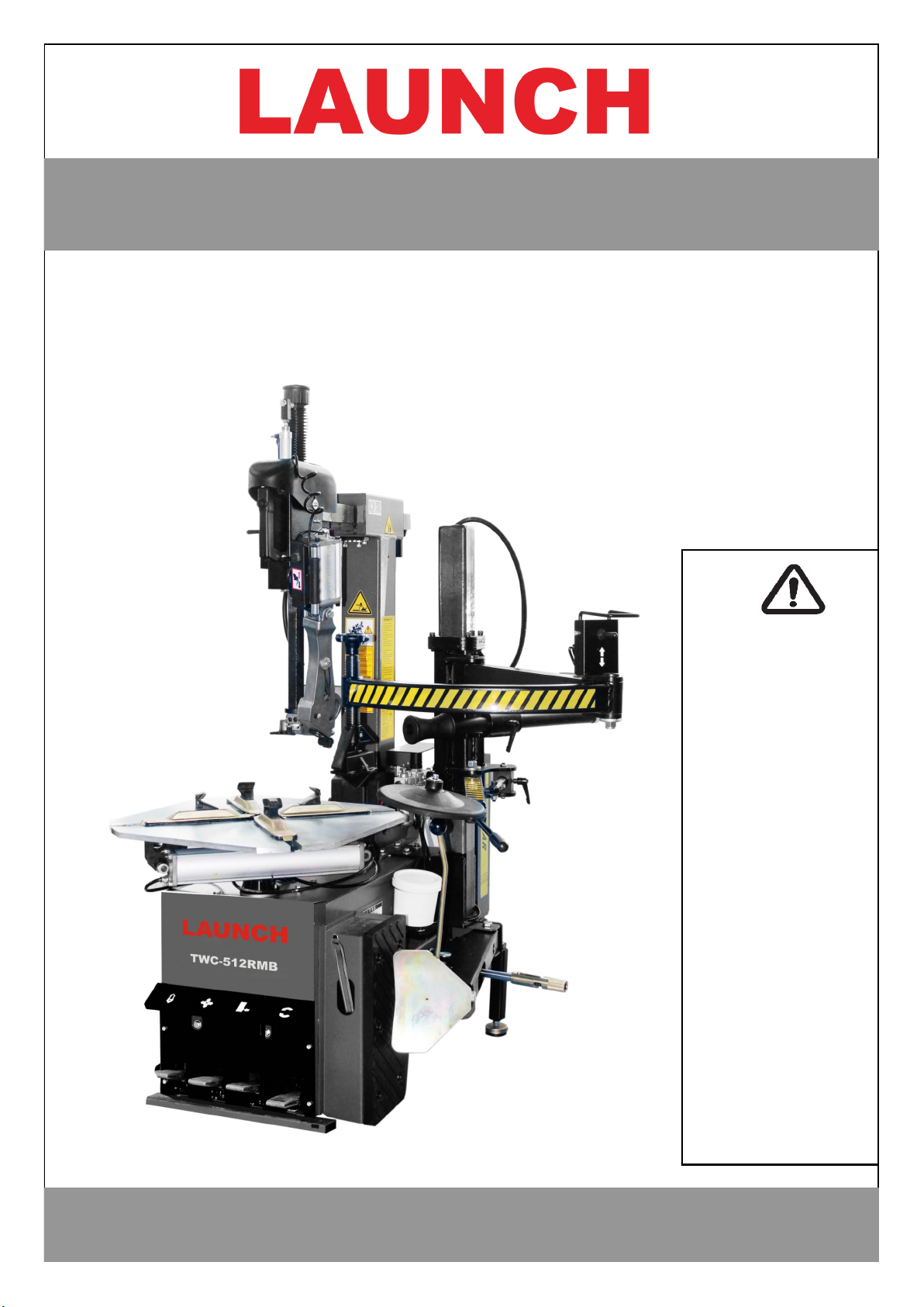
Operation Manual
Installation, Operation, Maintenance
TWC-512RMB
Tire Changer
Page 2
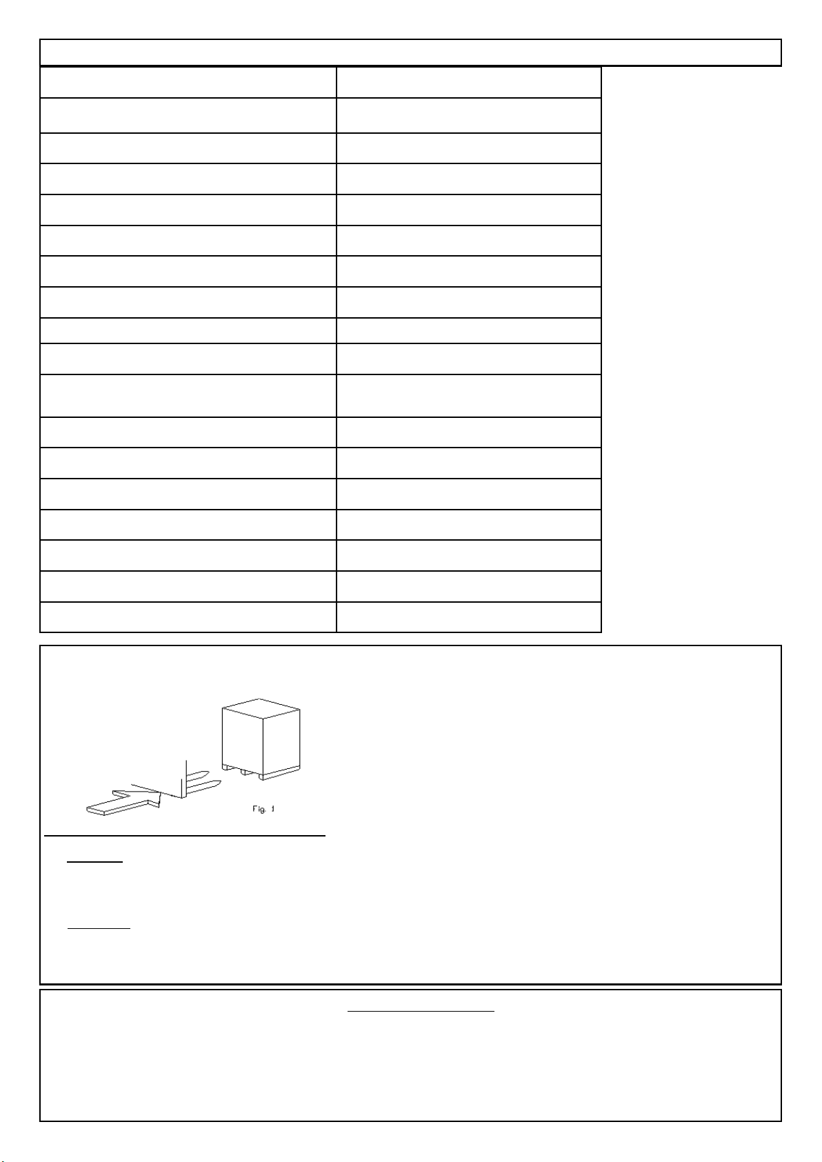
(1) Technical Data
Model
Electric Requirements See the manufacturer’s serial plate
Max. Wheel Diameter 42‖
Max. Wheel Width 14‖
Outside Clamping—Rim sizes 11‖ ~ 21‖
Inside Clamping—Rim sizes 13‖ ~ 23‖
Max Inflation Pressure 116-145PSI (8-10 Bar)
Bead Breaker Force 2500kgs
Max Rotating Torque (Turntable) 795 ft.lbs (1078N.m)
Noise Level
<70db
Overall Dimensions (L x W x H)
Shipping Weight 385kg
Voltage 0.9 ~ 1.1 of nominal voltage
Frequency 0.98~1.02 of nominal frequency
Ambient Temperature 5~40°C
Operation Humidity 30~95%
Installation altitude NOT exceed 1000m
Transport / Storage temperature -25~55°C
(2) ASSEMBLY INSTRUCTION
Fig.1
2-1 Transport
When transporting the machine it must be handle with a forklift truck with the forks
Positioned as show as in the Fig.1.
2-2 Unpacking
When unpacking, check to make sure all parts shown on the spare parts List/Assembly. Diagrams are included. If any parts
are missing or broken, please call the manufacturer or the dealer as soon as possible.
(3) Workplace Requirements
The machine’s workplace requires 1400(width)×1685(depth) with at least 500 mm of clear space from each wall. Place the tire
changer on a firm, smooth and unbroken floor. Drill four holes in the floor corresponding to the holes pre-drilled in the base of
the machine. Holes should be 80mm deep. Its diameter is 10mm. Then insert the expansion plugs and lighten with the 10mm
spanner.
Page 3
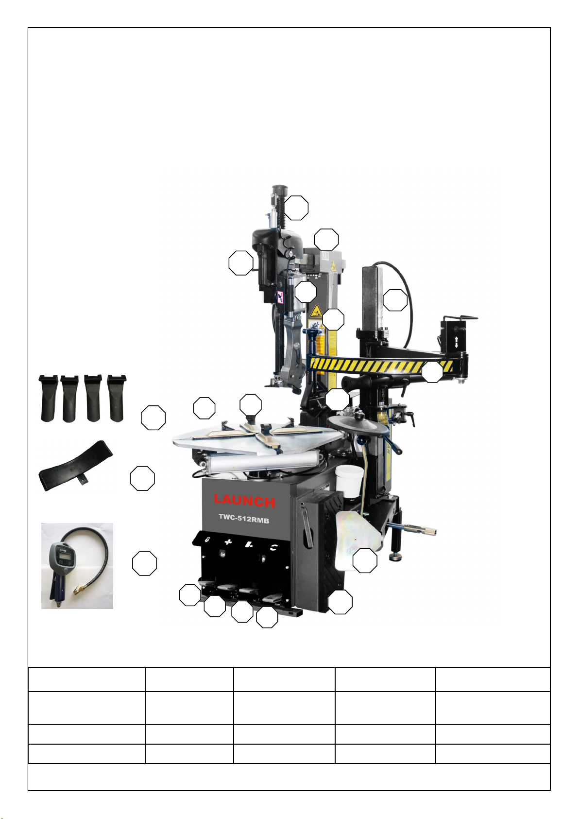
(4) Product description
1
2
3
4
5
6
7
8
9
11
13
14
15
16
17
18
19
12
10
1.padel(rotating) 2.turntable 3.padel (clamping) 4.Jaw 5.padel (title back)
6.vertical column 7.padel (bead
breaker)
8.shovel arm 9.ULMH 10.hexagonal column
11.control handle 12.slide arm 13.HDFRL 14. shovel 15.rubber wheel support
16.DAAR 17.LPJP 18.BBSPP 19. Inflation gun
Page 4
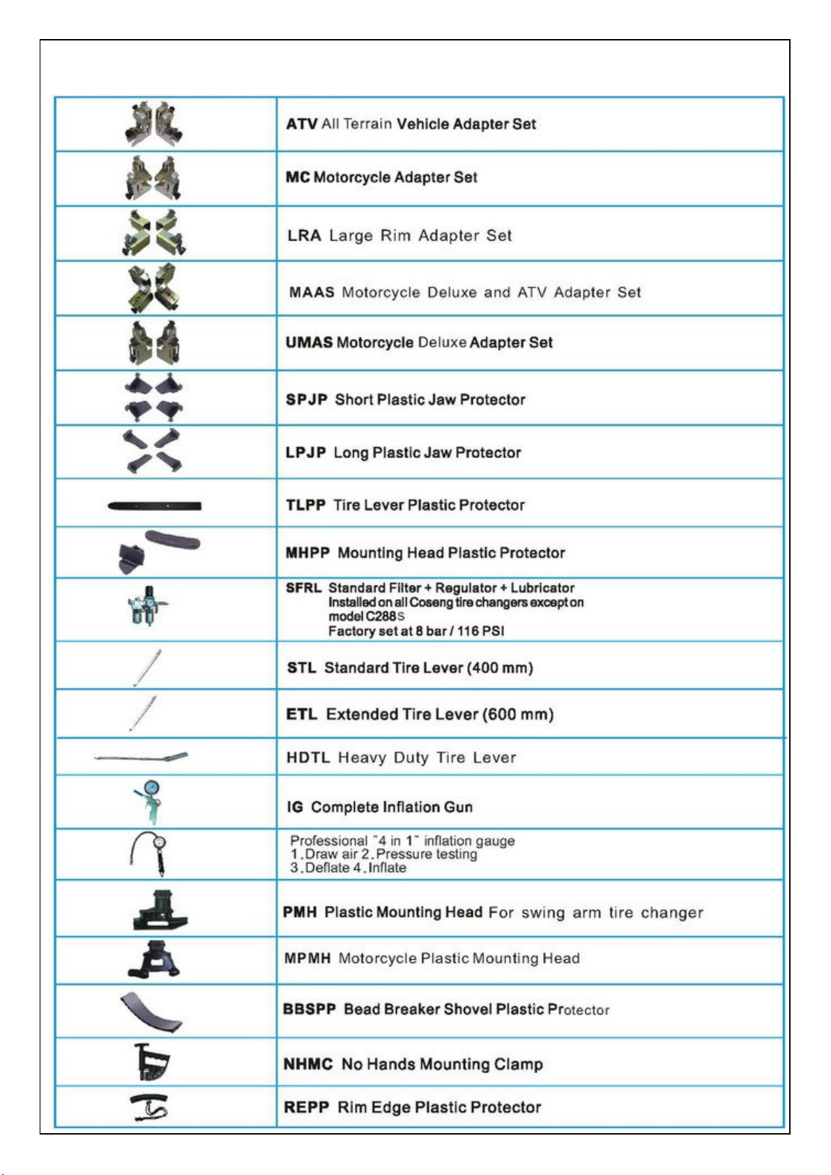
(5) Optional Upgrade Accessories
Page 5
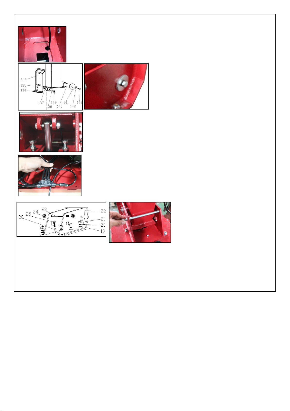
Step 1. With assistance, place the vertical column in its tilt back seat on the Body Assembly. Push the air hose
through the large round hole into the body.
Step 2. Insert the pin (140) through the column and fasten it with
screws (143) and washers (142).
Step 3. Using the screw (137) tighten with the self-locking nut (139) and washer (138) to connect the pin
of the post tilting cylinder.
Step 4. Remove the four screws from the left side cover and remove it. Connect the air hose from the column to the 6mm connector.
Step 5. Replace the side cover and fasten with its screws.
Step 6. Install the plastic guard (134) and fix it with the screws and washer (135,136).
Step 7. Install the stopper bolt (23) with self lock nut
(24). Don’t too tight.
5-2 Pneumatic link up
1) Push the clamping pedal all the way down to ensure that the jaws on the turntable do not open unexpectedly.
2) Connect the inflation gun, if it is to be installed, to its connector.
3) Connect the tire changer to a compressed air network (suggested working pressure from 8bar) using the connector. Use a compressed air
hose with on inside diameter of 7~8 mm.
5-3 Electric link up
1) Before making any electric link up, check to be certain that the main voltage corresponds to what is stamped on the voltage tag.
2) It is absolutely essential that the system is equipped with a good grounding circuit.
3) The machine must be connected to a power supply line circuit bracket set for 30mA
(6) Assembly procedure
Page 6
(7) Bead Loosening and Demounting
This machine may operate differently from machines you
have previously operated. Practice with a regular steel
wheel and tire combination to familiarize yourself with
the machine’s operation and function.
A. Remember to remove all weights from both sides of
the wheel. Weights left on backside of wheel may cause the
wheel to be clamped unleveled. This may result in the combination mount/demount head contacting the rim causing
scratches. On alloy wheels, always rotate the wheel one turn
after setting the Mounting head to insure proper wheel
chucking.
B. Always review with the owner any nicks and
scratches on expensive wheel and tire combinations prior to
servicing.
C. Review the custom and special wheel section of this
manual prior to servicing custom or special tire/wheel combinations.
Loosening the beads on a partially or fully inflated tire is
unsafe and causes excess movement and friction against
the bumper pads and excessive wear on pivots. Deflate
the tire completely to prolong the life of your machine.
1. Deflate the tire completely by removing the valve core
from the valve stem (figure 1). Be cautious and do not smoke
as a flammable gas could have been introduced into the tire
at some time.
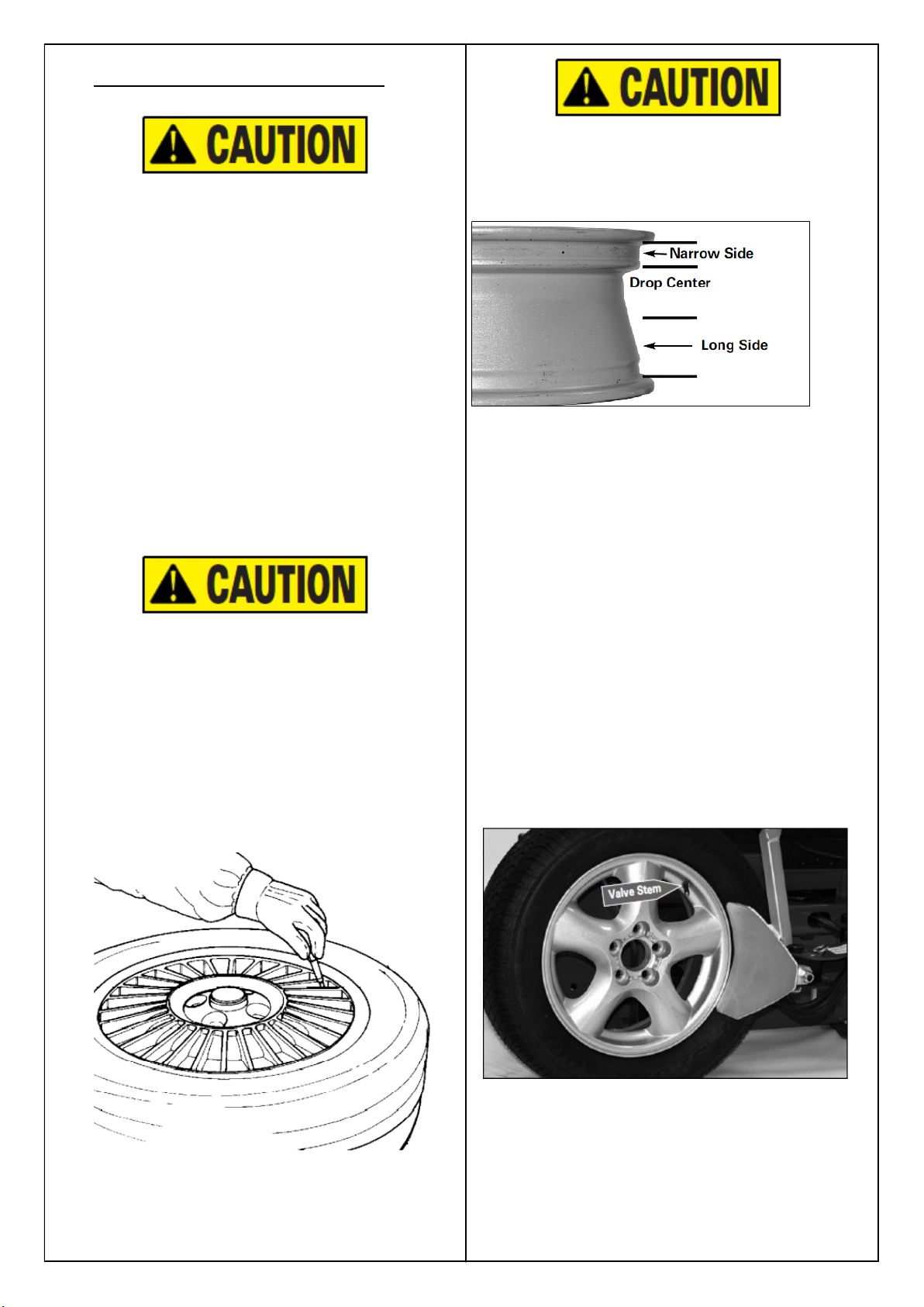
Tires are always installed and removed from the rim’s
narrow side.
D. Always loosen the bead on the narrow side of the
wheel’s drop center first (tire removed in figure 2 for clarity).
Figure 2 - Determine Narrow Side of Wheel
Figure 1 - Remove Valve Core to Deflate Tire
E. The clamps on the table top may extend beyond the
table top itself. To avoid damaging the clamps, move them
to their full inward position before positioning a tire for bead
loosening.
F. Use extra care in positioning the bead loosener shoe
on larger wheels/tires, and on alloy wheels. Make sure the
shoe rests next to but not on the rim, and not on the tire
sidewall.
2. Pull the bead loosener shoe away from the machine and
roll wheel into position. The valve stem should be in the 2
o’clock position to accommodate a possible asymmetric
safety hump type rim. Position the bead loosener shoe
against the tire next to, but not on, the rim. Press the bead
loosener foot pedal to actuate the shoe and loosen the bead.
It may be necessary
to loosen the bead in multiple locations around the tire
(figure 3).
3. Turn the wheel around and repeat loosening procedure
on the other side of the wheel (figure 4). This should be the
long side of the drop center (figure 2).
Figure 3 - Position Tire and Bead Loosener Shoe
Page 7

1. it is important to understand that tires and / or tire beads do not stretch. It is nearly impossible to mount
dismount the top bead of the tire unless the to bead of the tire is positioned deep into the drop center area
of the wheel.
2. Find the position of the drop center on the wheel. Clearly identify the drop center, narrow side and wide
side flanges.
3. The tire must always be demounted or mounted with wheel positioned on the turntable with narrow side
facing upward and the deepest part of the drop center facing upward.
Warning—the wheel illustrated above in diagram A has little or no prominent drop center. These are
not dot approved wheel configurations. The tire or wheel—or both—can be damaged during mounting procedures causing the tire to explode under pressure, resulting in serious injury or death.
Important note –most aftermarket and many OEM performance wheels are REVERSE DROPCENTER configurations. These wheels must be mounted on the turntable with the hub or wheelface positioned downward on the turntable and the narrow side and deep art of the drop center facing
upward.
(8)Important
Page 8

4.Place tire/wheel assembly on table top with mount-
ing side up
5. use the clamp control pedal to move the clamps in-
ward or outward.
6. apply tire manufacturer’s approved rubber lubri-
cant liberally to entire circumference of both beads
after loosening bead and placing on table top. Using
the mount/ demount roller to hold down the top bead
while rotating the turntable will make lubrication
easier.
7. move the tower forward by depressing the tower tilt pedal
then press the control button to unlock the horizontal slide.
Pull the mount/demount head forward.
(9) How to demount and mount a tire
with using ULMH
9.1 before demount, make sure the bead is loose. Please
use the bead breaker to loose the bead. Then lubricate the
bead where hook push down.
9.2 if machine equips assistance arm, press down the
bead to show the bead lip
and gap. Then use the hand
control valve push down
the hook. (left picture). Return assistance arm.
9.3 the hook maybe not
under the bead lip because the bead is thick or
long. Please step on the
rotation pedal to counter
clockwise spin the tire.
9.4 during the rotation,
the tension of bead will
be bounced, so the hook
automatically is under
the bead lips.
Page 9

9.5 use a hand control valve to
raise up the hook, the bead lip
is the top of rim’s edge.
9.6 some tires such as runflat ,or low profile tires
needs extra force to reduce
stresses. Use the assistance
arm to press down on the
tire opposite the mounting
head to allow the bead to
utilize the drop center area
of the rim, this position reduce stresses in the bead and
allows an easier bead lift.
9.7 lubricate bead lip area
before rotate the wheel.
Lubricating the bead can
decrease the friction between hook, bead and rim.
It must be lubricated well.
9.8 during the demount,
bead lip maybe not jump
up the top of rim, please
use plastic bead lifting
lever to insert the gap between bead and rim. Hold
that position (see left picture) to keep bead is top of
the rim.
9.9 rotate the tire. Then
top bead lip is completed
loose.
9.10 use the hand control
valve to push down the
hook (lift picture).
9.11 use the hook to pull
out the bottom bead lip.
9.12 lubricate the hook
and bottom bead lip to
decrease frication during
the demounting.
9.13 lubricate the vertical
sleeve if bead is wider.
9.14 rotate the wheel to
demount the bottom bead
lip.
Page 10

(11) bead installation
(10) Mounting
Notice: check the wheel and bead any possible damage that maybe cause rick
11.1 first install bottom bead tip on the rim.
11.2 rotate the wheel and bottom bead will automatic pull
down. Depress table top pedal and rotate wheel to mount
lower bead. Use drop center of wheel by forcing down on
tire just ahead of the mounting tool, and follow as tire rotates. Rotate table top until lower bead is mounted.
11.3 the top bead lip must place on the ULMH tail. rotate the table top until the valve stem is directly across
from the mount head. Lift the upper bead up and over
the rear of the mount head. With assistance arm press
down on the tire between the mount head and the valve
stem to hold the tire in the drop center. Depress table
top pedal and rotate tire until bead is mounted. Be careful to ensure bead stays in the rim drop center in the
area ahead of Mounting head
11.4 If table top rotation stalls, reverse the table top momentarily until tire bead is again loose on the wheel. Reposition tire on Mounting head, make sure bead is correctly
positioned in drop center of the wheel; then attempt
mounting again.
11.5 For low profile or stiff sidewall tires, it may be advantageous to use the bead lifting tool to initially hold the upper bead down in the drop center.
Page 11

(10) Bead Sealing
1. Position valve stem in front of operator and connect the
inflation hose with the clip-on chuck. Hold tire up against
upper edge of the wheel. Be sure tire’s top bead does not cover
the bottom of the valve stem (figure 19).
Figure 19 - Lift Tire Upwards for Bead Sealing
2. Depress inflation pedal to position 2 and hold about one
second to begin air flow through tire valve, then depress
pedal to position 3 and hold briefly — less than one full
second. The blast of air from the jets will expand tire and
seal the beads.
3. Release the inflation pedal and allow it to return to position 1. Verify that both beads are completely sealed to the
wheel. Repeat these steps if beads have not sealed. It may
be necessary to wait a few seconds for the air storage tank
pressure to recover before attempting again.
1. Once tire pressure is indicated on the air gauge (inflation
pedal in position 1; foot removed from pedal), continue to
inject air into the tire (inflation pedal position 2) in short
intervals. Check the pressure frequently. Stand back during
bead seat. Keep hands, arms, and entire body away from tire
during this procedure (figure 20). Tire beads should move
outward and ―pop‖ into their bead seat position as pressure
inside the tire increases. If this does not happen, a problem
exists. Investigate carefully.
Use of bead sealing jets without a tire in place can cause
dirt and debris to be blown into the air with enough force
to injure operator and/or bystander. Do not use the bead
sealing control position to inflate a tire.
S. This unit is equipped with a pressure limiter to assist
the operator with proper tire inflation. When the inflation
pedal is held in position 2, the pressure limiter cycles the
machine between position 2 (inflation) and position 1 (at rest,
no airflow to tire). This cycling helps to prevent over inflation of the tire. Tires can still be over inflated and explode
with the use of this pressure limiter if all of the instructions in
this manual are not followed completely. The pressure limiter will keep most car and light truck tires from inflating
beyond 60 PSI (smaller tires may reach higher pressures). It
is the operator's responsibility to follow all instructions and
to control inflation pressure as specified in these instructions.
Check the function of the pressure limiter regularly and
maintain it according to the instructions provided in this
manual for safe and proper operation. Do not tamper with or
attempt to adjust the pressure limiter. Tires requiring inflation beyond 60 PSI should be inflated in a safety cage.
T. If tire and wheel are properly lubricated and operator
cannot achieve bead seal after three or four attempts, the
valve core may be removed from the valve stem to allow
more air flow into the tire to assist with bead seal. After
bead seal is achieved, remove the clip-on chuck and reinstall the valve core. Reattach the clip-on chuck after core
is installed.
Figure 20 - Stand Back during Bead Seat
(9) Inflation
Tire inflation is performed in three steps: BEAD SEAL,
BEAD SEAT, and INFLATION. These steps are explained
in detail on page 12. Read the explanation of each step and
understand them thoroughly before proceeding.
The inflation pedal, located at the rear of the left side of the
machine, controls the flow of air through the inflation hose,
and has three positions. Note: The clip-on chuck on the end
of the hose should always be an open/freeflow style with all
parts in proper working order.
Position 1 - Tire Pressure – With the inflation hose
attached to the tire valve and the pedal in this position, the air
gauge will register the air pressure in the tire. Whenever your
foot is removed from the pedal, it will return to this position.
Position 2 - Tire Inflation – This is the first activated
position. With the inflation hose attached to the tire valve and
the pedal in this position, line pressure is allowed to flow
through the valve system and into the tire for inflation. Correct tire pressure is not indicated on the gauge in this position.
Position 3 - Bead Sealing – This is the second and last
activated position. With the inflation hose attached to the tire
valve and the pedal in this position, line pressure is allowed
to flow through the valve and to the airflate bead seal jets on
the table top for bead sealing.
1. If the rim has been clamped from the outside for
tire mounting, release the clamps, lift the tire, and move the
clamps to the center of the table top.
Page 12

(11) Stages of Inflation on a Conventional Tire and Rim
Review these descriptions and diagrams carefully. Refer to them as necessary during bead sealing, bead seating, and inflation to
verify that you are proceeding properly and safely.
Bead Sealing
Bead sealing is the process of capturing air pressure between the tire and the rim. The tire will usually contain about 1/2 to 2 PSI
at initial bead seal.
Bead Seating
Bead seating usually occurs on the long tapered side of the wheel first and the shorter side last. Bead seating will usually require
at least 7 PSI in the tire. 40 PSI is the maximum safe pressure at this stage regardless of tire operating pressure. Most European
import cars and many aftermarket alloy wheels are very tight and can be difficult to bead seat. Also note that asymmetrical hump
and run-flat tires are extremely difficult to bead seat. Follow tire manufacturer’s recommended procedure for bead seating.
Inflation
After the beads are seated, the tire is ready to be inflated. Do not inflate the tire above the manufacturer’s recommended pressure
as stamped on the tire sidewall. The typical inflation pressure for automobile tires is between 24 and 45 PSI. Light truck inflation
pressure typically covers a wider range.
Page 13

4-IN-1 Tire Inflating Gun
instruction
(IP, or IT system will not include 4IN1 Tire inflating Gun)
Introduction
Under-inflation burns more fuel and leads to shortened tire life. Check your tire pressure at least
once a month. Every liter of fuel consumed by a small vehicle releases 2.4 kg of C02 or a truck 12
kg into the environment, contributing to climate change.
This Tire Inflation Gun is a vacuum gun, inflating gun, a deflating gun and a tire pressure meter allin-one. The Gun has durable steel construction with no moving parts to wear out.
Inflating Chuck
Vacuum Cap
Gauge
Intake
Trigger
3600 Rotatable
Inflating Chuck
Vacuum Cap
Gauge
Intake
Trigger
3600 Rotatable
Features
- Four functions works on tire maintenance; (1) vacuuming tire air, (2) inflating tire air, (3)deflating tire air and (4)measuring
tire pressure.
- This Gun has a chuck with a 13/15mm diameter, 400/1000mm long hose for 360 degree rotatable which allows it to connect
to a tire valve conveniently.
- A built-in large dual scales (0-16 bar/0-240 psi) gauge makes air pressures easy to read.
- This Gun can be used not only on automotive tires also in the other fields.
- This Gun facilitates users while changing a truck’s inner tire.
Operation
Vacuum Tire : Connect air source (Nitrogen) into the Gun’s intake valve, and inflating chuck into car tire chuck valve in appropriate places.
Spin the rotatable vacuum cap and press the trigger. Then, you can see the indicator of the meter move to bottom left, start vacuuming. Once
complete the vacuuming, spin back the rotatable vacuum cap, then can do tire inflation.
Measure Tire Pressure: Connect inflating chuck into car tire chuck valve in appropriate place, the meter will start indicating the tire pressure.
Deflate Tire: When you need to deflate an over-inflated-pressure tire, press the trigger to the half while inflating the tire till reaching the desired
tire pressure.
Inflate Tire: Connect air source (Nitrogen) into the Gun’s intake valve, and inflating chuck into car tire chuck valve in appropriate places. Turn
OFF the rotatable vacuum cap and press the trigger. Then, you can see the indicator of the meter move to top right, start inflating the tire.
Page 14

DAAR ARM INSTRUCTION MANUAL
1.GENERAL
The DAAR ARM has been designed as a tire changer accessory to help the operator to mount or demount tires.
Before any operation of this machine,the operator is requested to read the manual carefully. Do not attempt
any operations that are not stated in this handbook!Otherwise,the machine fail to operating correctly,
causing injuries or machine damages,we shall not be liable for that accidents!
Please keep this manual handy for consulting.
2. TECHNICAL PARAMETERS
Working Air Pressure
8~10 bar
Net Weight 100kg
Noise Level
LpA<70Db(A)
3. SAFETY REGULATIONS
The operator must be a well –trained professional personnel.
This device could only function when work together with our tire changer.
We won’t responsible for any unauthorized modifications.
4. INSTALLATION
NOTICE:
The installations of this auxiliary device should be done by an professional
personnel.
Before any assemblies,turn off the power of both electricity and compressed air.
!
TRANSPORTAION
Move the machine with a forklift truck as illustrated in Fig.1.
UNPACKING
Remove the packaging carefully and check the machine, if there are any damages or defects,please
contact with us or with the dealer timely.
Please keep the packaging out of the children’s reach.
Please keep the packaging for possible future needs
Page 15

4.3 WORKPLACE REQUIREMENTS
Fig.2 shows maximum machine space requirements and minimum distance of 500mm from walls.
Screw M10
Screw M10
4.4 ASSEMBLY
The following steps show how to install the DAAR ARM.
1)Disconnect the tire changer from the electric power source and the compressed air circuit.
2)for installation of DAAR ARM. Pull the DAAR ARM to right side of machine. Using a M10 Screw mount
the tire changer.
3)Connect the air hose (Ø8mm) that introduced through the rear hole of the box with the corresponding
joint of T-union.
4)For IT version, connect the hose (Ø6mm) through the body to the fittings of the five-way valve ac-
cording to corresponding marks.
for installation of DAAR ARM. Pull the DAAR ARM to right side of machine. Using a M10 Screw mount the
tire changer.
Page 16

5. LAYOUT OF FUNCTIONAL PARTS
Right picture shows functional members of the DAAR ARM
1. valve Control Unit
2. axle guideboard
3. back swing arm
4. axle guard cover
5. shaft
6. bead roller
7. cylinder
8. bead breaker handle
9. u shape arm
10. mounting block
11. disk handle
12. bead breaker disk
1
1
2
1
4
1
5
1
6
1
7
1
8
1
9
1
10
11
12
3
1
6. SPECIFECATION OF SWITCH LEVEL
Controlling the switch level could attain the rise or decline of the tool holding arms.
7. TRIAL OPERATION
The operations of the DAAR Arm need the power both of electricity and compressed air.
The DAAR Arm must connect with air compressor, and 8 bar air pressure is desirable.
8. SAFETY REGULATIONS
WARNING:
Unreadable or missing warning labels must be replaced immediately.
Operations are not permitted when one or more labels are missed.
It is not allowed to prevent the view of the operator to see the labels when running the machine.
It’s reasonable to set up some labels as right picture shows.
!
9. OPERATIONS
The DAAR ARM has been designed to facilitate the operations of wheel locking and mounting/demounting
the tire on or from the rim. These operations,especially with low profile or very wide sports car tires or with
very hard beads,can be very difficult. In any case,the DAAR ARM would make these jobs easier on any
type of wheel.
Page 17

9.1 CLAMPING THE TIRE
Correctly follow this manual, release the beads both side of the tire.
It’s more forceful to use the DAAR ARM. Clamping the tire from out-
side is recommended. (Plastic protections are available ).
1. Depress the corresponding pedal to open the jaw and turn the
spindle to its non-working position.
2. lay the wheel onto the turntable, depress the corresponding
pedal to close or open the jaws for the clamping of the rim.
9.2 DEMOUNTING THE TIRE
1. Firstly break and loosen the beads if it is necessary.
Loosen the locking nut to lower the pressing roller, make sure the roller is above
the tire and not touching it.
Turn the switch level to bottom, lower the tool holding arm 1 to press the tire with
pressing roller. Depress the corresponding pedal to turn the turntable to loosen
the bead. Turn the turntable repeatedly if it is necessary.
NOTICE:
Before any operations, lubricate the bead of the wheel.
After loosen the bead, raise tool arms and begin the next demounting.
Demount the upper bead.
Close the mounting head to the upper bead as the manual stated.
Move the pressing roller near the mounting head, depress the bead for the convenience of position-
ing the mounting head, and then insert the level into the clearance between the rim and bead.
Raise the auxiliary arms, swivel the tool holding arm 2 to the opposite side, control the mounting head,
insert it into the
drop-center rim, and the tire will slide into the center drop. This could
get enough space for operations.
Pull out the bead with the help of mounting head and hang it on the
mounting head.
Raise the auxiliary arm, push the mounting head to its non-working po-
sition.
Depress the pedal to turn the turntable; the upper bead will be detached
off.
3. Loosen the second bead if it is necessary.
Push away the switch arm and tool holding arm3.
Position the bead-breaking disc under the tire, and make sure it close
to the tire other than touch the tire.
Insert the level into the special hole and exert an inner-toward force to as-
sure the bead breaking disc touch against the lower bead tightly. Depress the pedal to turn the turntable, meanwhile raise the auxiliary
arms slowly to detach the lower bead.
Page 18

NOTICE:
For some tires could be disassembled by only using the bead breaking disc, so it is enough continue the
third step until the tire was detached off.
Combination with the bead-breaking disc make it is easer to demount the wider tires and sport car tires.
Raise the lower bead up to center drop of the rim with the help of the bead-breaking disc.
Hook the detached part of tire on the mounting head.
Remove the bead-breaking disc; turn the turntable clockwise until the lower bead comes off the rim.
9.3 MOUNT TIRES
1) Set up the first bead according to instruction
2) WARNING!
Push away the tool holding arms to avoid danger of collision!
Move the mounting head and depress it to a depth of 3 cm blow the
upper side of the rim.
DANGER!
3) Please pay special attention during this procedure,pressing the
rim with the mounting head is not permitted. It will lead to danger.
Keep away hands from the mounting head.
4) Depress the corresponding pedal to turn the turntable, the
mounting head mechanism will turn also. Depress the tire blow into
the rim. During this procedure,it is free from any human interference
or other assistors.
10. TROUBLESHOOTING AND MAINTENANCE
Phenomena
Switch level is not flexible
Analysis
1)Disconnected with compressed air
2)Air hose is folded or broken
3)Valve is broken
Solution
1)Connect with the compressor according to the manual
2)Inspect the air hose, replace the broken hose and joint
3)Please contact with the department of after sale
 Loading...