

Page 1

LAUNCH Tyre Changer(TWC Series)
General Notice
Trademark Information
is a registered trademark of LAUNCH
TECH. CO., LTD. (LAUNCH for short) in China and
other countries. All other LAUNCH trademarks,
service marks, domain names, logos, and company
names referred to in this manual are either
trademarks, registered trademarks, service marks,
domain names, logos, company names of or are
otherwise the property of LAUNCH or its affiliates. In
countries where any of the LAUNCH trademarks,
service marks, domain names, logos and company
names are not registered, LAUNCH claims other
rights associated with unregistered trademarks,
service marks, domain names, logos, and company
names. Other products or company names referred to
in this manual may be trademarks of their respective
owners. You may not use any trademark, service
mark, domain name, logo, or company name of
LAUNCH or any third party without permission from
the owner of the applicable trademark, service mark,
domain name, logo, or company name. You may
contact LAUNCH by visiting Launch at
http://www.cnlaunch.com, or writing to LAUNCH,
Xinyang Building, Bagua 4th Road, Shenzhen,
Guangdong Province, P. R. C., to request written
permission to use Materials on this manual for
purposes or for all other questions relating to this
manual.
Copyright Information
Copyright © 2000 by LAUNCH TECH. CO., LTD. All
rights reserved. No part of this publication may be
reproduced, stored in a retrieval system, or
transmitted in any form or by any means, electronic,
mechanical, photocopying, recording or otherwise,
without the prior written permission of LAUNCH. The
information contained herein is designed only for the
use of this unit. LAUNCH is not responsible for any
use of this information as applied to other units.
Neither LAUNCH nor its affiliates shall be liable to the
purchaser of this unit or third parties for damages,
losses, costs, or expenses incurred by purchaser or
third parties as a result of: accident, misuse, or abuse
of this unit, or unauthorized modifications, repairs, or
alterations to this unit, or failure to strictly comply with
LAUNCH operating and maintenance instructions.
LAUNCH shall not be liable for any damages or
problems arising from the use of any options or any
consumable products other than those designated as
Original LAUNCH Products or LAUNCH Approved
Products by LAUNCH.
Other product names used herein are for
identification purposes only and may be
trademarks of their respective owners.
LAUNCH disclaims any and all rights in
those marks.
i
Page 2

LAUNCH Tyre Changer(TWC Series)
Safety Precautions
Attention
l This manual is a necessary part of the product.
Please read carefully.
l Keep the manual for later use when maintaining
the machine.
l This machine can only be used for the
designated purposes. Never use it for any
other purpose.
l The manufacturer is not held responsible for the
damage incurred by improper use or use other
than the intended purpose.
Precautions
l The equipment can only be operated by qualified
personnel with special training. Modification to
any components or parts, or use the machine for
other purpose without either obtaining the
agreement from the producer, or observing the
requirement of the instructions may lead to direct
or indirect damage to the equipment.
l The machine should be installed on the stable
ground.
l Keep the back panel 0.75M away from the wall
for good ventilation. Enough room should be left
on both sides of the machine for convenient
operation.
l Do not put the machine in a place with high
temperature or moisture, or near the heating
system, water tap, air-humidifier or chimney.
l Do not put the machine near the window with
sunlight. Protect the unit with a curtain or
shield if necessary.
l Avoid lots of dust, ammonia, alcohol, thinner or
spraying binder.
l People who are not operating the machines
should be kept away when it is used.
l Use appropriate equipment and tools, protective
and safety equipment, including eyeglasses,
earplugs and working boots.
l Pay special attention to the marks on the
machine.
l Do not touch or approach the moving parts by
hand during operating.
l Do not remove the safety device or keep it from
working properly.
l Use #2 lithium lubricants (grease) only within the
safety range. Refer the appendix for the safety
data.
l Before moving the tyre changer, contact
maintenance personnel.
ii
Page 3
LAUNCH Tyre Changer(TWC Series)
MAX 10bar
of
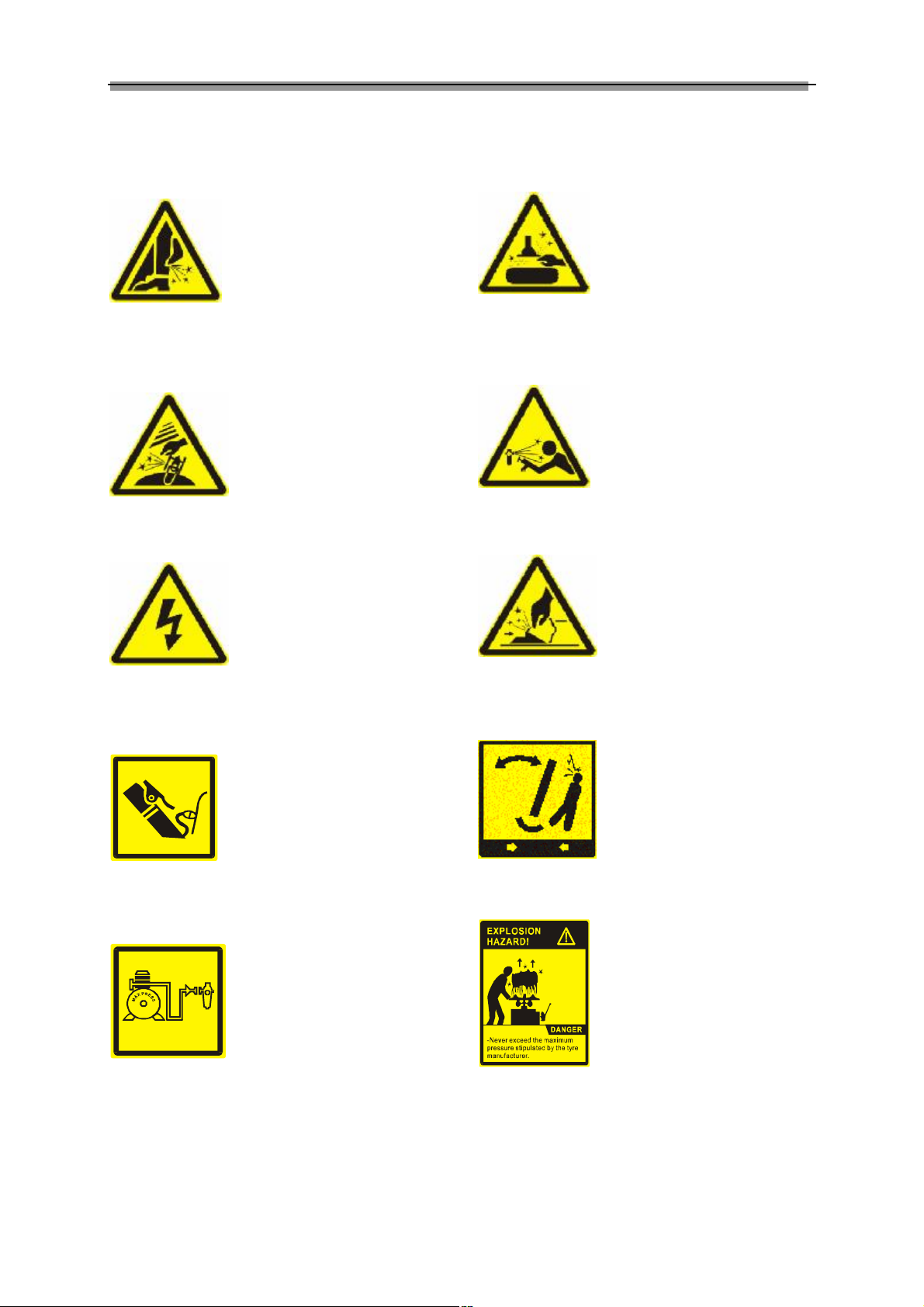
² Caution should be taken
when separating the tyre
bead from rim. The bead
breaker shoe will move
rapidly and forcefully when
the pedal is depressed.
Keep hands and other parts
of body away from moving
parts.
² If the clamping cylinder is
working when bead
breaking, to avoid
squeezing hands,
remember to keep hands
away from the sidewalk
tyre.
² High voltage power!
Danger!
² This is where the
compressed air gun is
connected with the air pipe.
Connect the compressed air
gun with the air connector.
² The pressure of the
compressed air should not
exceed 10 bar.
Description of Safety Signs
² To prevent accidents from
occurring, make sure to
keep hands and other parts
of the body away from
moving parts when
fastening the mounting
head or when the turntable
is running.
² Be careful when connecting
and disconnecting air
source. Exhaust the air in
the cylinder completely
when maintaining the air
pipes to prevent accidents
from occurring.
² Don’t keep hands or other
body parts between the
clamping jaw and clamping
rim.
² Pay attention to the safety
regulations in the swinging
area of the tilting post to
avoid accidents from
happening.
² Before inflating check if the
clamping rim and the tyre
match each other, and if
they are in good condition.
Any negligence may result
in fatal explosion. Similar
accident may occur if the
inflating air exceeds the
allowed tire pressure.
iii
Page 4
LAUNCH Tyre Changer(TWC Series)
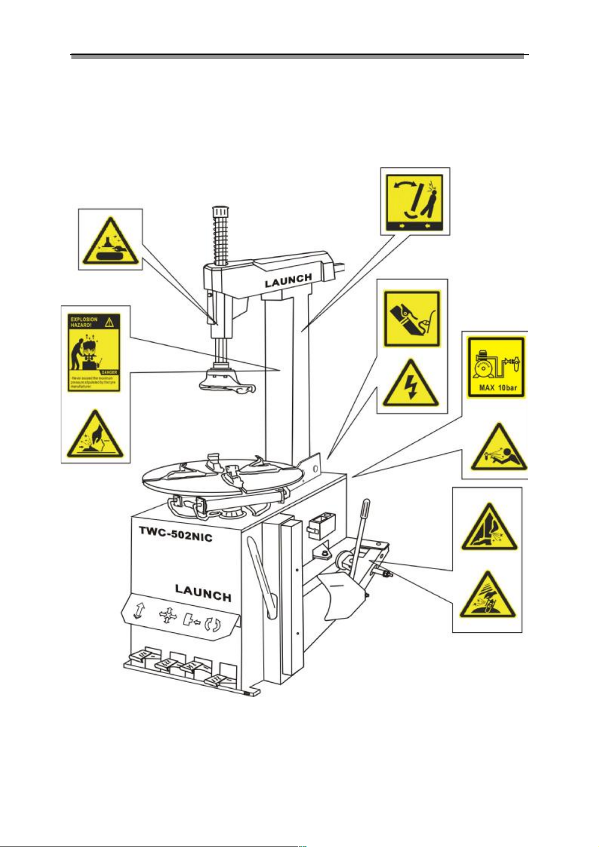
The Position of Safety Signs
Take TWC-502NIC as example:
u Please replace the safety signs if it gets blurred or lost.
u When one or more safety signs get lost, don’t operate the machine.
u The safety signs must be kept within the sight of the operator.
iv
Page 5

LAUNCH Tyre Changer(TWC Series)
Table of Contents
General Information………………………………1
Rules to Name TWC Series….………….…1
Usage… …………………………….……….…2
Features …………………………………...…..2
Technical Specifications………………………..2
Applicable Range……………………...…..2
Working Conditions……………..………….2
Main Structure ……………………...……..…3
Operation ………..……………………..………4
General Regulation…………………….….. 4
Demounting Tyre………………………….….. 4
Mounting Tyre …………………………………6
Inflating Tyre ………………………………..… 7
Right Supplementary Arm……………………8
Left Supplementary Arm……………………11
Troubleshooting ……………………………14
Maintenance………………………………..…15
Optional Device- Digital Inflator….……...…17
Storing ……………………………..………….18
TWC Series Oil Safety Data…………...….19
TWC Series Circuit Diagram….. .. ... ....…20
TWC Series Pneumatic Diagram. ..... ..….23
v
Page 6
LAUNCH Tyre Changer(TWC Series)
General Information
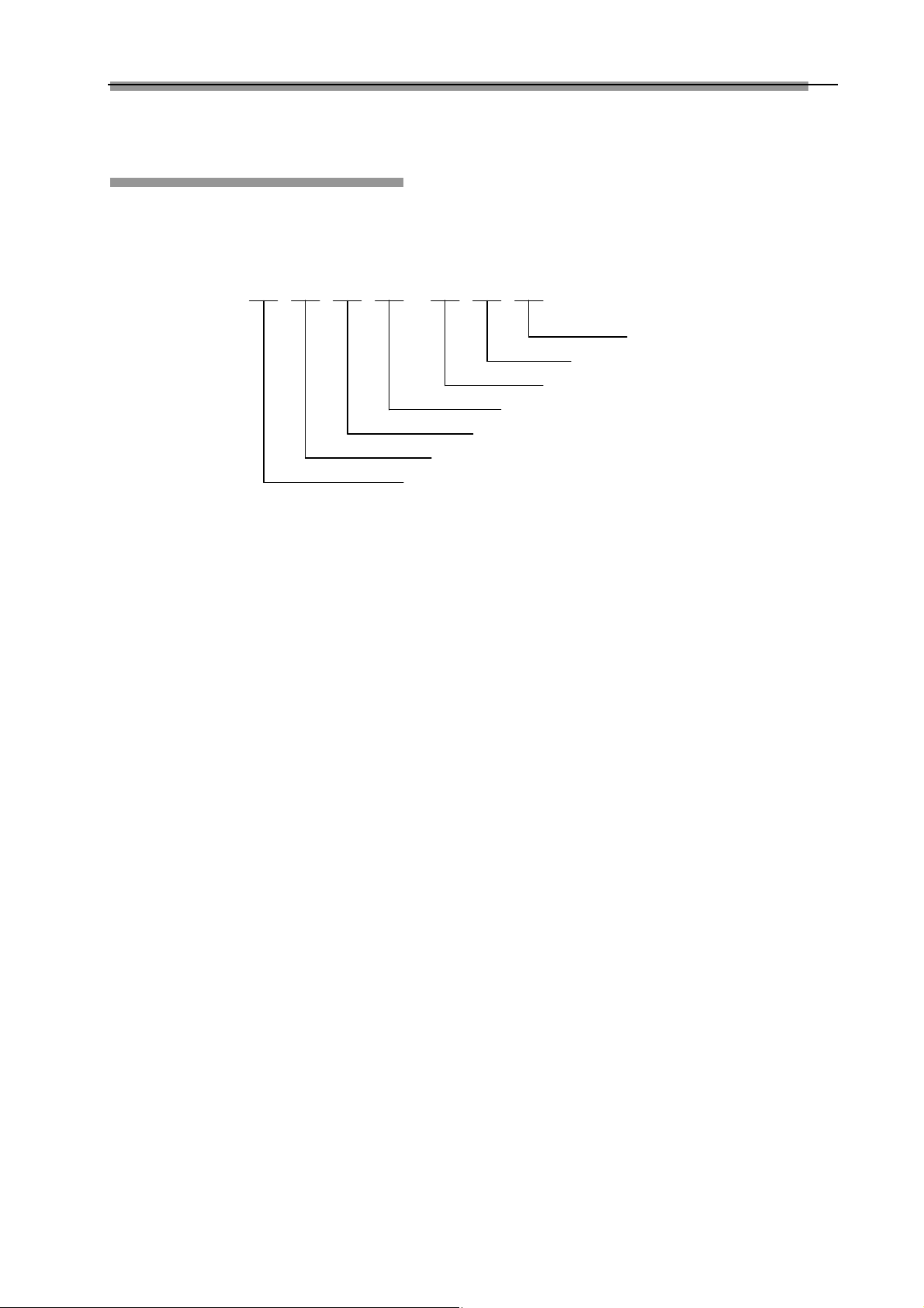
Rules to name TWC series
TWC- means tyre changer
T W C – 5 0 2 R D B +
⑦
⑥
⑤
④
③
②
①
Meaning of code:
①- for rim clamping diameter: 4 stands for 10” ~19”(20”);
5 stands for 10” ~23”(24”);
6 stands for 10” ~26”;
②- for shape of turntable: 0 stands for round turntable;
1 stands for square turntable;
2 stands for cross turntable;
3 stands for asymmetric turntable;
③- post working mode: 1 stands for swing arm (semi-automatic);
2 stands for tilting arm(automatic);
3 stands for swivel arm (automatic)
④- for supplementary arm information: R stands for right supplementary arm;
L stands for left supplementary arm;
D stands for double supplementary arm;
N stands for none supplementary arm;
⑤- for inflating device: I stands for inflating gun;
M stands for meter inflating box;
D stands for digital inflating gauge (LED display);
⑥- for inflating mode: B stands for quick inflator;
C stands for normal inflating;
⑦- for roller set: + stands for roller set;
For example:
TWC-502RDB+--------- the tyre changer’s rim clamping diameter is 10″-23″(24″). It is equipped with round turntable, tilting
post(automatic), right supplementary arm, digital inflating box(LED display), quick inflator and roller set.
1
Page 7

LAUNCH Tyre Changer(TWC Series)
Applicable Range
Usage
TWC series are used for demounting, mounting and
inflating tyres of small and medium vehicles.
Mount/demount help device and quick-inflating device
features simple operation and high reliability. In addition, it
can also be a great help in car repair garage and tyre
dealers.
Model Max wheel diameter
4 series 960mm(38")
5 series 960mm(38")
6 series 1050mm(41")
Max rim width
360mm(14")
380mm(15")
380mm(15")
Working conditions
Features
l Integrate demounting, mounting and inflating, wide
rim diameter capacity
l The steel mount/demount is cast from excellent alloy
material with special shape and durable performance.
The supplied plastic mount/demount head with the
equipment is made from special engineering plastic
that has enough intensity and will not damage the
tyre or the rim.
l The two clamping cylinder ensures accurate central
alignment, so that the rim can be held tightly.
l Pedal set designed for ergonomical use
l With adjustable opening, bead breaker is
suitable for tyres of different sizes
l Tyre lever and lubricant box within the reach of
operator technical specifications
Working temperature: -40℃-45℃
Transport/store temperature: -40℃-55℃
Humidity: 30-95%
Altitude: less than 1000m
Technical data
Model Height Length Width Weight
TWC4*1** 1705mm 1020mm 810mm 204kg
TWC4*2** 1725mm 1020mm 810mm 218kg
TWC5*1** 1820mm 1015mm 870mm 228kg
TWC5*2** 1880mm 1350mm 950mm 320kg
TWC6*2** 1880mm 1350mm 950mm 340kg
Electric specifications
Voltage alternatives:
A C110V(±5%) 60Hz(±1Hz)
AC220V(±5%) 50Hz(±1Hz)
AC230V(±5%) 60Hz(±1Hz)
Power: 1.1Kw
Phase: Single
RPM of turntable: 6-8r/min
Air supply
Working pressure: 8-10bar
Bead breaker force: 14075N
Noise
Working noise: <70dB(A)
2
Page 8
LAUNCH Tyre Changer(TWC Series)
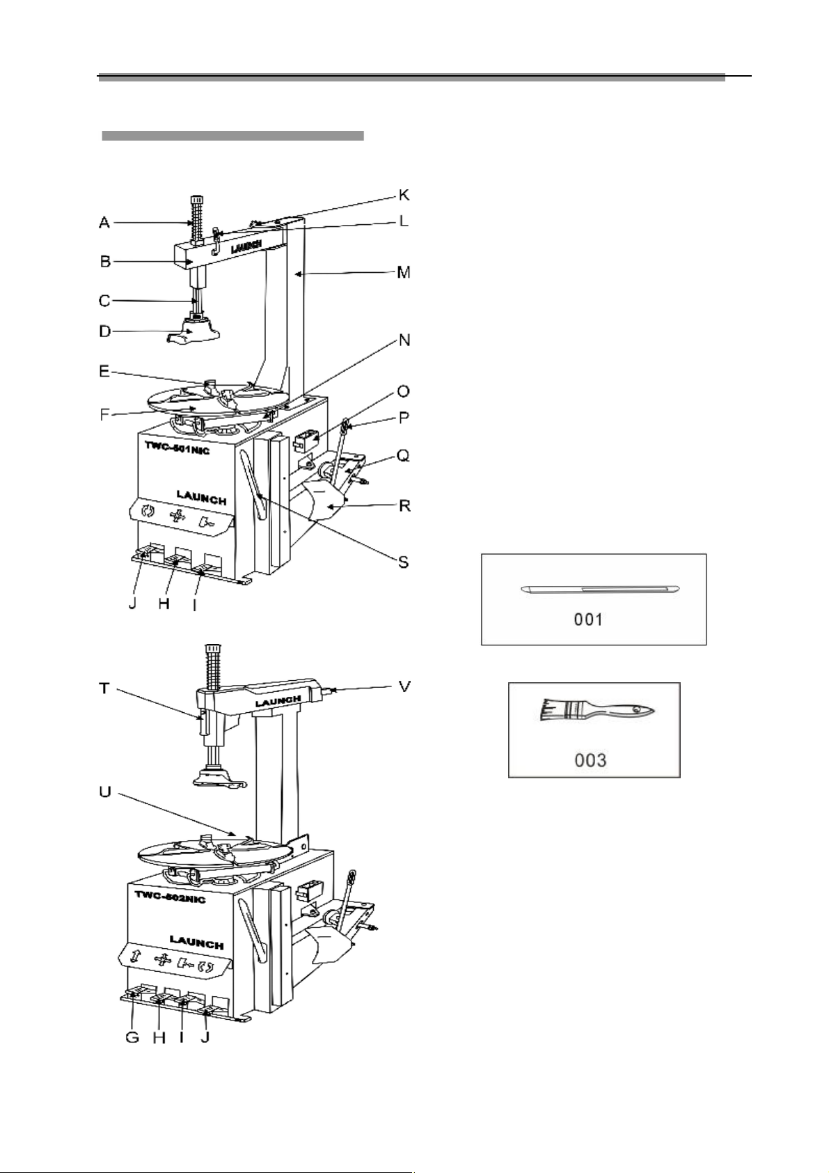
Main Structure
The main structure is shown in Fig. 01.
A. Return spring
B. Swing arm
C. Hexagonal column
D. Mount/demount head
E. Clamping jaw
F. Turntable
G. Tilting post control pedal
H. Clamping cylinder control pedal
I. Bead breaker control pedal
J. Turntable control pedal
K. Knob
L. Locking lever
M. Post
N. Clamping cylinder
O. Lubricant box
P. Bead breaker handle
Q. Bead breaker arm
R. Bead breaker shoe
S. Tyre lever
T. Locking handle
U. Air pressure regulator, gauge and lubricator assembly
V. Horizontal arm.
Accessories provided are shown in Fig.02
001-Tyre lever
002-Brush
Fig.01-1
Fig.02-a
Fig.02-b
Fig.01-2
3
Page 9
LAUNCH Tyre Changer(TWC Series)
Operation
Attention:
The machine is only to be operated by specially
trained and authorized personnel. Use appropriate
equipment, tools and personal protective equipment,
such as eye-glasses, ear-plugs and working boots,
when operating the tyre changer. Make sure that the
power, air sources and the oil level in the oil cup are
in accordance with the requirements.
General Regulations
l To avoid damage when mounting and demounting
tyre, especially the alloy ones, use the tyre lever
offered by manufacturer.
l For easier demounting and better protection of the
tyre and rim, lubricate the area between the rim and
tyre bead, where the bead breaker shoe goes in,
with industrial lubricant or thick soap solution.
l Pay special attention to rotary direction marked on
some flanges or tyres.
l Fit the tyre on the rim of matched size.
l Check for damages (distortions, surface damages,
excessive runout, erosion or overall wear) before
demounting.
l Never ignore the mounting and demounting
requirements of the special wheel.
l When inflating the tyre, make sure the pressure
increases in an even way. Pay attention to status of
the tyre bead.
tyre bead from wear. (Fig. 04).
Fig.04
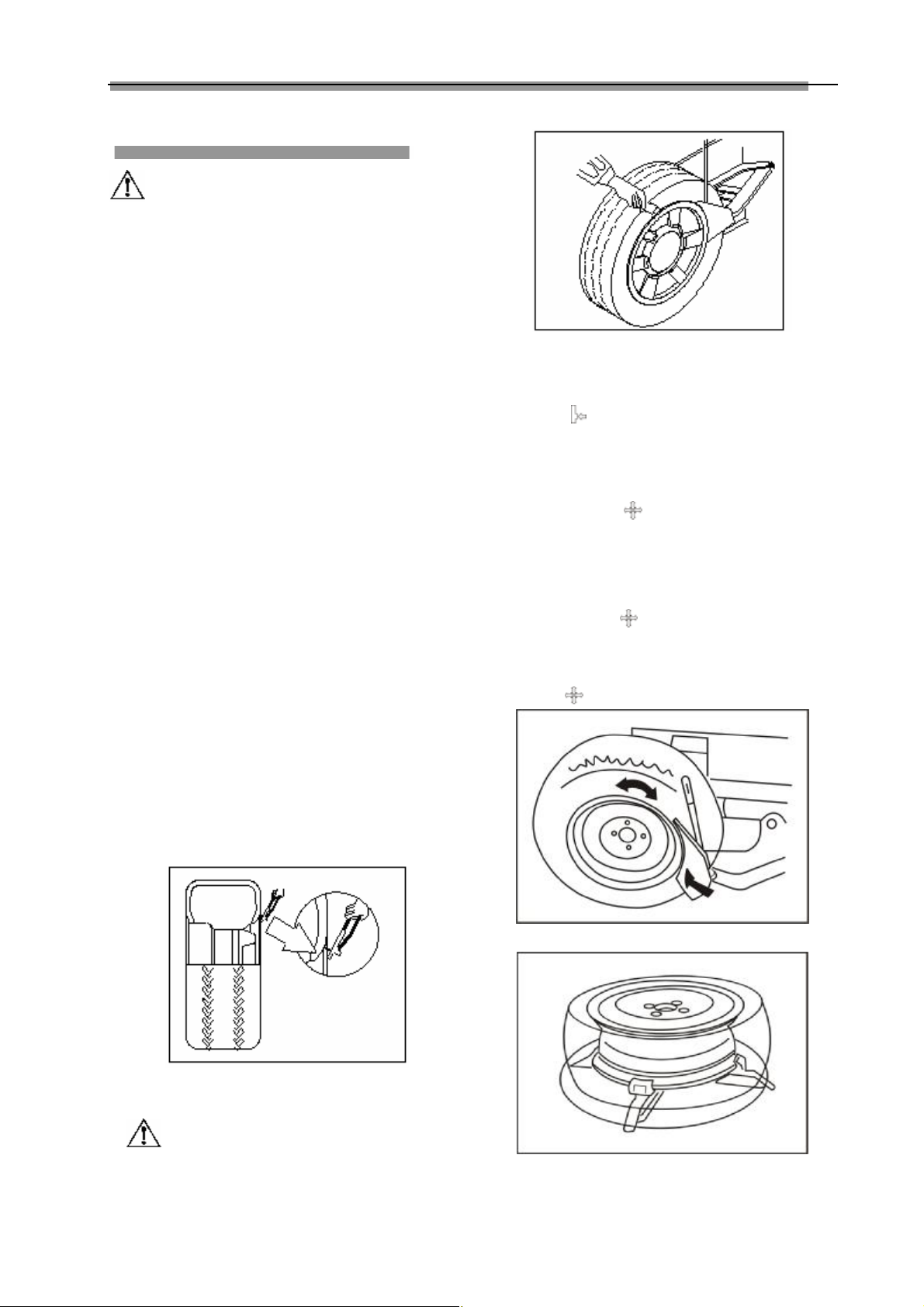
l Place the tyre between the bead breaker shoe and
rubber pad and position the bead breaker shoe max
1 cm away from the rim flange (Fig. 05). Depress
pedal “ ” to unseat bead from rim.
l Repeat the above steps to unseat bead thoroughly
from the rim.
l Place the wheel on the turntable. For the asymmetric
deep groove rim, keep the narrow rim upward.
l Depress pedal “ ” to the end to clamp the rim.
Attention: Different types of clamping can be chosen
in accordance with different rims.
Ø In case of inward clamping, shrink the jaws
together, place the wheel on the turntable and
depress pedal to clamp.
Ø In case of outward clamping, enlarge the jaws
outward (2-3cm away from periphery of the rim)
and place the wheel on the turntable and depress
pedal to clamp it (Fig. 06).
Demounting Tyre
Preparing
l Deflate the tyre thoroughly.
l Remove all the foreign substance and weights from
the rim (Fig. 03).
Fig.03
Demounting
Attention:
Lubricate the bead with a brush dipped in soap
solution before bead breaking in order to protect
Fig.05
Fig.06
4
Page 10

LAUNCH Tyre Changer(TWC Series)
Tyre changer with swing arm:
l Pull back the swing arm(3, fig.07) to working position,
adjust hexagonal column(4) up and down to make
mount/demount head 1-2 mm away from rim flange
to protect rim(fig.09), turn knob (12)to lock swing arm,
and turn locking handle(2) clockwise to lock
hexagonal column.
Tyre changer with tilting post:
l Depress pedal “ “ to restore the tilting post to its
working position (Fig.08).
l Press the hexagonal column and adjust hexagonal
column and horizontal arm to make mount/demount
head 1-2 mm away from rim flange to avoid
scratching rim(fig.09). Press button (a) (fig.08) on the
locking handle to lock the hexagonal column.
Attention:
The angle of the mount/demount head has been
adjusted by manufacturer according to standard rim
(15"). Re-adjustment may be necessary to prevent
scratching the tyre when the rim is extremely large or
small.
Lift the tyre bead onto the demount/mount head with tyre
lever( to make it easy, press down the tyre opposite to the
mount/demount head)(fig.10) Depress pedal “ ” to
turn the turntable clockwise until bead is unseated. To
avoid damage to the tube when where is one, it is
advisable to place the air inflating valve about 10 mm
(fig.11) away from the mount/demount head.
Fig.07
Fig.08
Caution:
In case the demounting is hindered, stop the machine
immediately. Lift up the pedal “ ” to turn the
turntable counter-clockwise to clear away the
hindrance.
l If there is tube in the tyre, remove it first.
l Lift the lower tyre bead so that the rim at the relative
side enters the groove (fig.12), use tyre lever to lift
the lower bead onto the mount/demount head.
l Depress pedal “ ” to separate the lower bead from
rim.
l Depress pedal “ “ to loose the jaw to take the
rim off.
Fig.10
Fig.11
Fig.09
5
Page 11

LAUNCH Tyre Changer(TWC Series)
Fig.12
Caution:
Keep hands and the rest of human body away from
the moving parts of the machine. Never wear necklace,
bracelet or loose clothes when operating the machine
as it may cause danger!
Mounting tyre
Attention:
Check the size of tyre and rim to see if they match
each other.
l Clamp the rim tightly in the same way as demounting
tyre.
l Use lubricant such as thick soap solution on the tyre
and the rim.
Tyre changer with swing arm:
l Place the tyre onto the rim at an angle to the
turntable, left side higher, pull back the swing arm in
working position.
Tyre changer with tilting post:
l Place the tyre onto the rim at an angle to the
turntable, front side higher(fig.13), depress down
pedal “ “ to restore the post (fig.13), adjust the
mount/demount head to right position, finally, press
locking button.
Fig.14
l Adjust relative position between the tyre and the
mount/demount head to position the tyre bead above
the left lip of the head (fig.15A) and below the right
lip(fig.15B).
Fig.15
l Press down the sidewall of the tyre. Depress the
pedal “ “ to turn the turntable clockwise, making
the lower tyre bead fall into the rim groove
completely.
l If a tube needs to be installed in the tyre, check first
for the possible damages. Round it onto the rim.
Make sure to keep the tube in the right position
throughout the mounting process.
l To install the upper tyre bead and adjust position of
the tyre bead (same as mount of the lower tyre bead
in Fig. 15). Draw out the roller and keep its side
surface 1—2cm away from margin of the rim. Place
the press block on the upper bead 20cm clockwise
away from the mount/demount head. Press the
control lever to make the press block go down
5—7cm to press the sidewall by hands to seat tyre
bead into the rim groove (Fig. 16).
Fig.13
6
Page 12

LAUNCH Tyre Changer(TWC Series)
manufacturer’s requirements. The pressure should
not exceed 3.5 bar. The user may adjust the
reducing valve in the machine to get different
pressures according to requirements.
Quick-inflation:
l If the tyre is tubeless or the tyre does not match the
rim hermetically, inflation method above-mentioned
will has no effect. In this case, the quick-inflation
should be adopted. The quick-inflation method is to
depress pedal “ ” to lock the rim, then depress the
Fig.16
l Depress the pedal “ “ to turn the turntable while
keeping pressing on the tyre. When only 10—15cm
is left, slow down to avoid damage of the tyre bead.
Stop the motor if there is any indication for damage.
Lift the pedal “ ” by foot to turn the turntable
counter-clockwise. Try again after making the tyre
back to the original shape.
Attention:
u If the rim size does not change, it is not
necessary to loose the locking handle
after finishing the mount and demount of
the tyre and adjust the mount/demount
head before mount and demount of tyre.
The operation will be continued by
depressing the column tilting control
pedal to make the titling column let go
and restore automatically.
u Make sure nobody is behind the tilting
post when depressing pedal (G).
u In the process of clamping, keep head
and hands away from the area between
the tyre and the horizontal arm in case
injury would be incurred.
inflation pedal on right-hand of the cabinet to its
end quickly and loose the pedal immediately. The
quick-inflation is finished with a rat-tat.
Attention:
Make sure that the tyre is clamped tightly, otherwise it
has danger of death.
Warning: Danger of explosion!
The safety procedures should be closely followed.
Review and abide by the following instructions.
Otherwise serious injury or death can be resulted.
The manufacturer shall not be held responsible for
any possible accident when the safety procedures are
not followed.
u Carefully check the dimensions of rim and
tyre to see if they match each other. Check
and make sure that the tyre is not worn or
damaged before inflation.
u When a high pressure is required, remove the
tyre from the tyre changer and resume the
inflation in a special protective hood.
u Be careful when inflating the tyre. Keep
hands and other parts of human body away
from tyre.
Inflating tyre
Danger!!
Inflating can be highly dangerous. Take precautions
and pay close attention to the procedures. Check
pressure gauge and air circuit are in good condition
before inflating.
The machine is equipped with a gauge to read the
pressure in the tyre.
l Loose the wheel on the turntable.
l Connect the outlet of the inflating device to the air
inflation valve as shown in Fig.17.
l Slowly and repeatedly depress the inflation pedal (to
avoid over-high pressure) to make sure that the
reading on pressure gauge within the
Fig.17
7
Page 13

LAUNCH Tyre Changer(TWC Series)
Right Supplementary Arm
Structure (Fig.18)
Demounting Tyre
l After breaking bead from the rim completely
following procedures described in last chapter, use
the supplementary arm to simple operation.
l Use the cone to simple operation of outward
clamping. Open the jaws outward (2-3cm away from
periphery of the rim) and place the wheel on the
turntable. Draw out the back swivel arm, fit and aim
the cone at the central hole of the wheel (fig.19),
press down the control lever to keep the rim close to
the jaws, and depress pedal “ ” to clamp it
(fig.20), remove the cone.
Fig.19
Fig.18
a- Slider
b- Press block
c- Fore swivel arm
d- Control box
e- Roller
f- Cone
g- Disk
h- Control lever
i- Back swivel arm
j- Sliding guide
k- Post weldment
l- Slide board
m- Roller arm
n- Disk arm
o- Lifting cylinder
Operation
Attention:
Ø The supplementary arm is specially designed for
TWC series pneumatic tyre changer of LAUNCH.
Never mount it on other machines, otherwise,
LAUNCH shall not liable for any accidents.
Ø The supplementary arm unit has function of
automatic self-centering. The back swivel arm
moves to center of turntable, it will lock
automatically. Lift the control lever to unlock.
Fig.20
l Draw out the roller and make it close to the tyre bead.
Press down the control lever to move the roller
downward 3-5cm, depress the pedal “ “ to turn
the turntable clockwise lubricating the tyre bead by a
brush (fig.21).
8
Page 14

LAUNCH Tyre Changer(TWC Series)
tubed tyre, it is advisable to keep the air inflation
valve to the right of the mount/demount head about
10 cm away to avoid damaging.
l If there is tube in the tyre, remove it first.
l Draw out the disk, and make the disk under the
lower bead, but not under rim. Insert the tyre lever
between the head and bead and press it down. Lift
the control lever up to break the bead from rim
groove. Make the lower tyre bead opposite to
mount/demount head enter into the rim groove, and
prize the lower tyre bead onto the ball protuberance
Fig.21
(fig.24).
l Adjust the mount/demount head to right position and
lock it following the procedures in last chapter.
l Insert the tyre lever into between the mount/demount
head and the tyre bead. Lift the control lever to move
the roller to its none working position (fig.22).
Fig.22
Turn the swivel arm, and place the press block on the tyre
opposite to the mount/demount head. Lower down the
control lever to press down the block 5-6cm, then prize the
tyre bead onto the mount/demount head(fig.23). (The
positions of the mount/demount head and tyre bead are
described in last chapter.)
Fig.23
l Move the press block to its none working position,
depress the pedal “ “ to turn the turntable
clockwise until the rim is separated. In case of a
Fig.24
l Restore the disk and depress pedal “ “ until the
lower tyre bead is separated from the rim. Depress
the pedal “ ” to lose jaws, finally remove the tyre
and rim.
Attention:
Keep hands and other body parts away from the
moving parts of the machine. Never wear
necklace, bracelet or loose clothes when
operating the machine as it may cause danger!
Mounting tyre
Attention:
Check the size of tyre and rim to see if they match
each other.
l Seat the lower bead following procedures in last
chapter.
l If it is a tubed tyre, check first for the possible
damages. Round it onto the rim. Make sure to
keep the tube in the right position throughout the
mounting process.
l To seat the upper tyre bead, place the tyre well and
readjust position of the tyre bead (same as mount of
the lower tyre bead). Draw out the roller and make
its side surface 1—2cm away from margin of the rim.
Place the press block on the upper bead 20cm
clockwise away from the mount/demount head.
Press the control lever to make the press block go
down 5—7cm to seat tyre bead into the rim groove
9
Page 15

LAUNCH Tyre Changer(TWC Series)
(Fig. 25).
Left Supplementary Arm
Structure (fig.27)
Fig.25
l Depress the pedal “ ” to turn the turntable
clockwise. When only 10—15cm(Fig.26) is left, slow
down to avoid damage of the tyre bead. Stop the
motor once there is any indication for damage. Lift
the pedal to turn the turntable counter-clockwise. Try
again when the tyre is back to the original shape.
Fig.26
10
a- Post
b- Cone
c- Hood
d- Sliding guide
e- Spacer pin
f- Back swivel arm
g- Control box
h- Control lever
i- Fore swivel arm
j- Disk
k- Disk arm
l- Roller
m- Cylinder
1- Locking clip
2- Knob
3- Roller
Fig.27
Page 16

LAUNCH Tyre Changer(TWC Series)
②,③, press down locking clip and move the roller
Operation
Attention:
to the position 2-3cm away from rim. Lower down
control lever to depress down tyre 3-5cm as ④,
finally, pull out the knob as ⑤.
Ø The supplementary arm is specially designed for
TWC series pneumatic tyre changer of LAUNCH.
Never mount it on other machines, otherwise,
LAUNCH shall not liable for any accidents.
Ø The supplementary arm unit has function of
automatic self-centering. The back swivel arm
moves to center of turntable, it will lock
automatically. Lift the control lever to unlock.
Demounting Tyre
l After breaking bead from the rim completely
following procedures described in chapter operation,
use the supplementary arm to simple operation.
l Use the cone to simple operation of outward
clamping. Open the jaws outward(2-3cm away from
periphery of the rim) and place the wheel on the
turntable. Draw out the back swivel arm., fit and aim
the cone at the central hole of the wheel (fig.28),
press down the control lever to keep the rim close to
the jaws, and depress pedal “ ” to clamp it
(fig.29), remove the cone.
Fig.28
Fig.30
l Depress the pedal “ “ to turn the turntable
clockwise, lubricating the bead with brush.(fig.31)
Fig.31
l Adjust the mount/demount head to right position and
lock it following the procedures in chapter operation.
l Move the front swivel arm to the position as in figure
32, pull out spacer pin as ①, press down the knob
as ②, lower down control lever as ③ to press down
tyre 3-5cm, insert tyre lever between the head and
the bead as ④, finally lift the lever to restore the
roller.
Fig.29
l Draw out the swivel arm and position it as in figure
30, press down the spacer pin (①,fig.30) to lock the
fore swivel arm under back swivel arm. Following
Fig.32
11
Page 17

LAUNCH Tyre Changer(TWC Series)
Turn the fore swivel arm, and place the press block on the
tyre opposite to the mount/demount head. Lower down the
control lever to press down the block 5-6cm, then prize the
tyre bead onto the mount/demount head with tyre
lever(fig.33). (The positions of the mount/demount head
and tyre bead are described in chapter operation.)
Fig.33
l Move the press block to its none working position,
depress the pedal “ “ to turn the turntable
clockwise until the rim is separated. In case of a
tubed tyre, it is advisable to keep the air inflation
valve to the right of the mount/demount head about
10 cm away to avoid damaging.
l If there is tube in the tyre, remove it first.
l Draw out the disk, and make the disk under the
lower bead, but not under rim. Insert the tyre lever
between the head and bead and press it down. Lift
the control lever up to break the bead from rim
groove. Make the lower tyre bead opposite to
mount/demount head enter into the rim groove, and
prize the lower tyre bead onto the ball protuberance
(fig.34).
Fig.34
l Restore the disk and depress pedal “ “ until the
lower tyre bead is separated from the rim. Depress
the pedal “ ” to lose jaws, finally remove the tyre
and rim.
Mounting tyre
Attention:
Check the size of tyre and rim to see if they match
each other.
l Seat the lower bead following procedures in chapter
operation.
l If it is a tubed tyre, check first for the possible
damages. Round it onto the rim. Make sure to
keep the tube in the right position throughout the
mounting process.
l To seat the upper tyre bead, place the tyre well and
readjust position of the tyre bead (same as mount of
the lower tyre bead). Draw out the roller and make
its side surface 1—2cm away from margin of the rim.
Place the press block on the upper bead 20cm
clockwise away from the mount/demount head.
Press the control lever to make the press block go
down 5—7cm to seat tyre bead into the rim groove
(Fig. 35).
Fig.35
l Depress the pedal “ ” to turn the turntable
clockwise. When only 10—15cm is left, slow down to
avoid damage of the tyre bead. Stop the motor once
there is any indication for damage. Lift the pedal to
turn the turntable counter-clockwise. Try again when
the tyre is back to the original shape.
12
Page 18

LAUNCH Tyre Changer(TWC Series)
Trouble Shooting
Symptom Cause Solution
Turntable can turn only in
one direction.
Turntable doesn’t turn. u Belt is damaged.
Turntable can not lock the
rim tightly.
Horizontal arm and
hexagonal column can’t be
locked.
Horizontal arm doesn’t move
after pushing or pulling.
Vertical shaft can not move
upwards or downwards.
Tilting post tilting is too fast
or too slow.
The locking valve is clogged
after the lever is pressed.
Pedal can not be restored to
its original position.
There is abnormal noise at
the moving part.
The motor does not turn or
the output torque is not
enough.
Cylinder is weak in output. u There is air leakage.
Air leakage is found. u Air hose is damaged.
u Power switch is damaged. u Replace the power switch.
u Power switch is damaged.
u There is problem with
motor.
u Belt is loose.
u Jaws are worn.
u Air leakage in clamping
cylinder.
u The locking square board
in wrong position.
u The locking hexagonal
board in wrong position.
u Square locking board is
not in correct position.
Hexagonal locking board
is not in correct position.
u The pushing cylinder
expels too much or too
little air.
u Pressure of compressed
air has not reached 8bar.
u O-ring of the valve is
damaged.
u There is problem with
airflow regulating valve.
u Return spring is damaged. u Replace the return spring.
u The fixing screw is loose.
u There is foreign matter
inside.
u The moving part is stuck.
u The capacitor is failed.
u The voltage is too low.
u The circuit is open.
u Mechanical hindrance is
causing the problem.
u The pressure of the
compressed air is not high
enough.
u The outlet of the air valve
is damaged.
u The gasket cement is
gone.
u Replace the belt.
u Replace the power switch.
u Check power wire of motor. If the motor
u Tension the belt.
u Replace the jaws.
u Replace the cylinder seal.
u Adjust them to right position according to
u Refer to the chapter “Maintenance”.
u Open the side cover of the cabinet,
u Replace the valve or O-ring.
u Adjust or replace the pressure regulating
u Replace the airflow regulating valve.
u Tighten the fixing screw.
u Get rid of the foreign matter.
u Get rid of the stuck point.
u Replace the capacitor.
u Pause and wait for the device to be
u Repair.
u Strengthen the seal.
u Fix the mechanical problem.
u Change the air source.
u Replace the related part.
u Add gasket cement.
u Add gasket cement.
is damaged, replace it.
this manual.
slightly adjust two air inflation regulators
by hand to smooth the movement, and
then tighten the cap.
valve.
restored.
13
Page 19

LAUNCH Tyre Changer(TWC Series)
Maintenance
Attention:
Only the specialized technician can perform the
maintenance. Before any maintenance, disconnect the
power and keep the plug within the sight of the
maintenance personnel. Shut off power and
compressed air, push the air valve switch to “Off”
position and depress pedal (H) for 3 or 4 times to
bleed the residual compressed air in the machine.
To keep the tyre changer in good condition and to prolong
the work life, it is necessary to do regular maintenance
according to the instructions on the user’s manual.
Otherwise, the normal operation and reliability of the
machine will be affected, or personal injury would be
caused.
l Keep the machine and working area clean, prevent
dust or foreign matter from entering the moving
parts.
l Keep the hexagonal column clean and dry (clean
with diesel as in Fig. 36).
l Keep the horizontal arm and horizontal pole clean
and lubricate them periodically so that it can move
expectably.
l Weekly clean the turntable, jaws, guideways (Fig.
37).
l Weekly clean and lubricate base pin.
l Weekly lubricate the faying surface between moving
parts and rubbing surface with lithium lubricant
(grease).
l Check the oil level in the oil cup regularly. If the oil
level does not reach the second line, fill SAE#20
(Fig.38).
l Regularly drain the condensed material in the air
cleaner.
l Regularly check and adjust the tension of the belt.
l Check all connecting parts and bolts regularly and
tighten them if necessary.
Fig.37
Fig.38
l Check and adjust the locking mechanism of
hexagonal column periodically to insure the
distance between hexagonal column and rim
(regularly 2~3 mm approximately) after the
hexagonal column is locked.
Attention:
Tighten the fixing screws (shown in Fig.39 as part A)
on the turntable after every 15 days of operation.
Fig.36
Fig.39
If the vertical clearance of the hexagonal column is
too much, adjust it according to the following steps:
l Shut off compressed air.
l Remove the protective hood of the hexagonal
column.
l Adjust the retaining nut of lead screw or the pushing
14
screw at the front of locking board by wrench.
l Turn on the compressed air and then check the
position after locking.
If the horizontal arm can not be moved smoothly or
Page 20

LAUNCH Tyre Changer(TWC Series)
the clearance is too much after locking, do the
adjustment according to the following procedures:
l Open the protective cover of the tilting post.
l Adjust the M6 screws at both ends by wrench and
push the arm at the same time until it can be
moved smoothly. Then tighten the nut.
l Adjust the screw at middle by wrench and lock the
horizontal arm to see the change until the
clearance is satisfactory. Then tighten the nut.
Periodically clean the control valves for clamping
jaws and bead breaker to insure their normal
operation.
l Remove the side cover of the cabinet.
l Loosen the control valve muffler and air bleed
valve muffler, and clean them with compressed air.
(Fig.40)
Fig.40
15
Page 21

LAUNCH Tyre Changer(TWC Series)
l An inflation pipe that is 9 meters in length is supplied
Optional Device – Digital
Inflator
Performances:
l Accurate measure make reading right and inflation
time short
l LED display clear, particular suitable for night and
outdoor reading
l Finish measuring air pressure and inflation at the
same time, making operation quick and convenient.
l May preset values of inflation and deflation. When
the inflation gun is inserted into the tyre (non-empty
tyre), the device will automatically test and decide
inflation or deflation. When pressure of the tyre
reaches the set value, it automatically stop and warn
by the buzzer. When the tyre is empty and the
“RUN/STOP” key is pressed, the tyre is
automatically inflated to preset value.
l It can pause when the tyre is inflated or deflated.
l The device has swift function of air pressure unit and
can show both Bar and Psi values.
l Beautiful appearance and convenient installation.
with the device. If extension of the pipe is necessary,
total length must not exceed 20 meters. Otherwise,
working precision will decrease, or even the device
can not work normally.
l When the device starts to work, the inflation gun
should be deflated and not connected with the tyre.
Thus, the zero air pressure is got correctly to ensure
precision.
l Connection between the inflation gun and the tyre
must be reliable and no leakage.
l When the device is used, its power supply must be
far from the large power electrical applications.
Starting and stopping of these applications can
interfere the device accidentally. When interfere
caused by the momentary failure of the power supply
appears, sometimes abnormal errors will happen in
the computer of the device. The case can be
recovered to normal situation by that the inflation
gun head is moved and the power supply is off and
then on.
l Unit conversion:
1Mpa=l0Bar
1Bar=14.5Psi
2
1Bar≈1Kg/cm
Specifications:
l Working Range:0~8Bar (0~116Psi)
l Precision:0.1Bar(1.45Psi)
l Air Source:Pressure 6~9Bar(87~130Psi)
Flow>0.2M3/min
l Inflation Speed:0.15 M3/min
l AC Supply:According to local power supply
l Working Temperature Range: -10℃—+50℃
l Humidity:<95%
l Power:20W
l Net Weight: 5Kg
l Dimensions :120×195×100mm
Use Precautions:
l Power supply must be connected with the ground
wire.
l See Figures 23 and 24 for pipeline connections of
the inflator.
l There are no air supplies for these serial products.
Air pressure of additive air supply must be under
9.5Bar. If not so, a reducing valve must be fixed at
input air pipe to ensure that the air pressure of
entering the inflator is under 9.5Bar.
l Compressed air must be passed the oil and water
separator (air pressure regulator, gauge and
lubricator assembly) at first, and then is connected
into the inflator to avoid eroding internal parts of the
device.
Fig.41
Operations:
l Air pressure unit is showed in “bar (b)” in this device.
It can be changed to “psi (p)” unit by that “bar/psi”
key is pressed.
l Choose right pressure according to specifications of
the tyre. Press “+” or “—” key to set right pressure
values that satisfy requirements of specifications of
the tyre.
l After the pressure value is set, connect the clamping
head of the inflation gun with the tyre. If the tyre own
16
Page 22

LAUNCH Tyre Changer(TWC Series)
pressure, the device will starts automatically. If the
tyre is empty, “RUN/STOP” key must be pressed one
time to start the device.
l When the device is working, it can be stopped if the
“RUN/STOP” key is pressed one time. If the
“RUN/STOP” key is pressed one time again, the
device starts again.
l When pressure of the tyre reaches to the preset
value, the buzzer works and the device stops.
Part Coding:
If necessary, please order parts from LAUNCH or dealers
according to part coding (16AG600AX).
Circuit Diagram:
Fig.42
Storing and Scrapping
Storing
When the equipment needs to be stored for a long time:
l Disconnect the power and compressed air.
l Lubricate all the parts: slide block and groove.
l Empty all the oil/liquid cups.
l Cover the equipment with plastic shield.
Scrapping
When the equipment can no longer be used, disconnect
the power and compressed air and dispose in
accordance with the local regulations.
17
Page 23

LAUNCH Tyre Changer(TWC Series)
TWC Series Oil Safety Data
No. 2 lithium lubricant
Item Quality Index
Cone penetration (1/10mm) 278
Drop point ℃ 185
Corrosion (T2 Copper, 100 , 24h)℃ No change in the copper
Wire separator (100 , 22h)%℃ 4
Evaporation (100 , 22h)%℃ 2
Oxidation stability (99 , 100h)℃ 0.2
Anti-erosion Grade I
Foreign substance (microscopic method)
Above 10 μm
Above 25 μm
Above 75 μm
Above 125 μm
Relative viscosity (-15 ,10s℃
-1
), /Pa·s) Lower than 800
Drip loss Lower than 8
Lower than 5000
Lower than 3000
Lower than 500
Lower than 0
SAE20 Lubricant
Density (15℃) 0.880
Flash point ℃ 213
Freezing point ℃ -21
Viscosity 40℃ 66.2
Viscosity 100℃ 8.2
Viscosity index 95
Item Quality Index
18
Page 24

LAUNCH Tyre Changer(TWC Series)
TWC Series Circuit Diagram
EN60947-3
EN60309
EN60947-2
Remarks
Remarks
EN60309
32A
Model
Model
32A/2P+E/230V/IP44
rated current 40A
Mennekes socket 536#
32A/2P+E/230V/IP44
Mennekes plug 274#
This protective circuit should be
fulfiled by the customer
Name
No.
:
protective current
QF1
industrial power
air-break switch
QF1
SOCKET
40A
19A
:
2
current
2.5mm
socket
switch
Name
SW1
industrial power plug
PLUG
turning,change the phase wire(Z1 and V1).
Remarks:if the motor movement is contrary to the right
32A
:
No.
industrial power plug
maximum current
111 3
1242 86 1O
9
75
Z1V1U4
U3
U2U1
AC110V
60Hz
19
Page 25

LAUNCH Tyre Changer(TWC Series)
EN60947-3
EN60309
EN60309
EN60947-2
Remarks
Remarks
This protective circuit should be
fulfiled by the customer
Model
Name
No.
:
QF1
protective current
20A
rated current 20A
air-break switch
QF1
16A
Model
Mennekes socket 536#
32A/2P+E/230V/IP44
32A/2P+E/230V/IP44
Mennekes plug 274#
socket
industrial power
SOCKET
32A
:
industrial power plug
maximum current
Name
No.
switch
SW1
industrial power plug
PLUG
AC230V
60Hz
2
1.5mm
9.1A
:
current
11
7 9
5
31
12
8 1O
42 6
turning,change the phase wire(Z1 and V1).
Remarks:if the motor movement is contrary to the right
Z1
V1
U3 U4
U2
U1
20
Page 26

LAUNCH Tyre Changer(TWC Series)
EN60947-3
EN60309
EN60947-2
Remarks
Remarks
EN60309
This protective circuit should be
fulfiled by the customer
Model
NameNo.
QF1
protective current:
rated current 20A
air-break switch
QF1
20A
Mennekes socket 536#
industrial power
16A
Model
32A/2P+E/230V/IP44
32A/2P+E/230V/IP44
Mennekes plug 274#
socket
switch
SOCKET
industrial power plug
maximum current:32A
11
Name
No.
12
SW1
industrial power plug
PLUG
turning,change the phase wire(Z1 and Z2).
Remarks:if the motor movement is contrary to the right
AC220V
50Hz
2
1.5mm
current:9.1A
9
5 7
1 3
21
1O
6 8
Z2Z1 U2
U1
2 4
Page 27

LAUNCH Tyre Changer(TWC Series)
Quick-inflating
TWC Series Pneumatic Diagram
P
A
φ14(fabric)
Gun Inflator
φ14(fabric)
A
φ8
S
P
PA
φ8
P
O
φ
8
Bead Breaking
φ8
φ8
φ
8
φ8
φ
8
P
A
φ35(fabric)
φ
10
φ
10
φ
10
φ
10
φ14
A
A
B
B
O
φ8
φ8
φ8
φ8
R
A
P
B
S
Jaw Clamping
R
φ6
A
P
B φ8
S
φ8
φ
8
R
A
P
B
S
φ8
φ8
A
B
φ6
A
B
Tilting Cloumn
φ6
φ6
B B
φ8
φ
8
Clamping
A
Help Lifting
B
φ6
φ6
S
B
P
A
R
A
φ6
22
Page 28

LAUNCH Tyre Changer(TWC Series)
Warranty
THIS WARRANTY IS EXPRESSLY LIMITED TO PERSONS WHO PURCHASE LAUNCH PRODUCTS FOR
PURPOSES OF RESALE OR USE IN THE ORDINARY COURSE OF THE BUYER’S BUSINESS.
LAUNCH electronic product is warranted against defects in materials and workmanship for one year (12 months) from
date of delivery to the user. This warranty does not cover any part that has been abused, altered, used for a purpose
other than for which it was intended, or used in a manner inconsistent with instructions regarding use. The exclusive
remedy for any automotive meter found to be defective is repair or replacement, and LAUNCH shall not be liable for any
consequential or incidental damages. Final determination of defects shall be made by LAUNCH in accordance with
procedures established by LAUNCH. No agent, employee, or representative of LAUNCH has any authority to bind
LAUNCH to any affirmation, representation, or warranty concerning LAUNCH automotive meters, except as stated
herein.
Disclaimer
THE ABOVE WARRANTY IS IN LIEU OF ANY OTHER WARRANTY, EXPRESSED OR IMPLIED, INCLUDING ANY
WARRANTY OF MERCHANTABILITY OR FITNESS FOR A PARTICULAR PURPOSE.
Order Information
Replaceable and optional parts can be ordered directly from your LAUNCH authorized tool supplier. Your order should
include the following information:
1. Quantity
2. Part number
3. Item description
Customer Service
If you have any questions on the operation of the unit, please contact us:
Tel: 86-755-82269474,
Fax: 86-755-82264570,
E-mail: overseasales@cnlaunch.com.
If your unit requires repair service, return it to the manufacturer with a copy of the sales receipt and a note describing
the problem. If the unit is determined to be in warranty, it will be repaired or replaced at no charge. If the unit is
determined to be out of warranty, it will be repaired for a nominal service charge plus return freight. Send the unit
pre-paid to:
Attn: Overseas Department
LAUNCH TECH. CO., LTD.
Xinyang Building,
Bagua 4th Road,
Shenzhen, Guangdong Province,
China
 Loading...