

Page 1

LAUNCH TLT830WA Product Manual
Copyright reserved! Without the written agreement of
Launch Shanghai Machinery Co., Ltd. (hereinafter
called “Launch”), no company or individual is
allowed to copy and backup this manual in any form
(electronic, mechanical, photocopy, recording or other
forms). This manual is specifically designed for the
use of Launch product, and our company doesn’t
undertake any responsibility for various consequences
caused as a result of applying it to the guidance of
operating other equipment.
In case of the equipment damage or loss due to the
accident of the user himself or third party, abuse or
misuse of this equipment, unauthorized change and
repair of this equipment, or not conforming to the
Launch has registered its trademark in China and
several foreign countries, with the symbol of
LAUNCH. Other trademarks, service symbol, domain
name, icon, and company name of Launch mentioned
in this manual belong to the property of Launch and
its subsidiary companies. In the countries where
Launch’s trademark, service symbol, domain name,
icon and company name haven’t been registered,
Launch declares its ownership on such unregistered
trademark, service symbol, domain name, icon and
company name. The trademarks of other products and
company names mentioned in this manual still belong
to the originally registered companies. Without prior
written agreement of the owner, nobody can use the
trademark, service symbol, domain name, icon and
operation and maintenance requirement of Launch,
Launch and its branches won’t undertake any
responsibility for the expenses and expenditures
generated.
For the equipment damage or problem caused as a
result of using other optional accessories or
consumables instead of original Launch product or its
recognized product, Launch won’t undertake any
responsibility.
Official statement: The purpose of other- productnames mentioned in this manual is to describe how to
use this equipment. Their registered trademarks still
belong to the original companies.
company name of Launch and other companies
mentioned in this manual. If you have any question,
please visit website of Launch:
http://www.cnlaunch.com or write to Sales Dept. of
Launch Shanghai Machinery Co., Ltd. at No. 661
Baian Road, International Automobile City Auxiliary
Parts Park, Anting Town, Jiading District, Shanghai
City to contact Launch
The product consists of the People's Insurance
Company underwriting
This equipment is for the use of professional technical
personnel or maintenance personnel.
Registered Tradem ark
i
Page 2
LAUNCH TLT830WA Product Manual
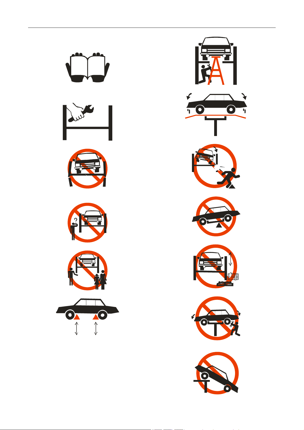
Caution labeling exemplify
(1)Read operating and safety manuals before using lift!
(2)Proper maintenance and inspection is necessary for
safe operation!
(3)Don not operate a damaged lift!
(4)Lift can be used by trained operators ONLY!
(8)Auxiliary adapters would reduce load capacity!
(9)keep area clear!
(10)the central of gravity should be between two arms!
(5)only Authorized personnel can be in the lift area!
(6)use commend lifting points!
(7)use bracket to help disassembly or installation!
(11)keep the area clean!
(12)do not shake the vehicle!
(13)do not lift single side of vehicle!
ii
Page 3

LAUNCH TLT830WA Product Manual
(14)keep feet clear when lowering!
(15)When lifting or lowering, don’t stand under the lift!
iii
Page 4

LAUNCH TLT830WA Product Manual
Table of Contents
1 NOTE ...............................................................................................................................................1
2 GENERAL INFORMATION.........................................................................................................2
2.1 APPLICATION..........................................................................................................................................................2
2.2 FEATURES..............................................................................................................................................................2
2.3 TECHNICAL SPECIFICATIONS .................................................................................................................................2
2.4 ENVIRONMENT REQUIREMENTS ............................................................................................................................. 2
3 STRUCTURE AND WORKING PRINCIPLE............................................................................3
3.1 STRUCTURE............................................................................................................................................................3
3.2 ELECTRICAL DIAGRAM ..........................................................................................................................................4
3.2 HYDRAULIC DIAGRAM............................................................................................................................................5
3.3 HYDRAULIC COMPONENTS IN CONTROL DESK ..................................................................................................... 5
3.4 PNEUMATIC DIAGRAM............................................................................................................................................ 6
3.5 OPERATION DESCRIPTION...................................................................................................................................... 6
4 INSTALLATION AND COMMISSIONING AND UNPACKING.............................................7
4.1 PLEASE GET THE FOLLOWING TOOLS READY FOR INSTALLATION:.....................................................................7
4.2 UNPACKING............................................................................................................................................................7
5. EQUIPMENT INSTALLATION..................................................................................................7
5.1 BASIC REQUIREMENTS...........................................................................................................................................7
5.2 INSTALLATION PROCEDURES.................................................................................................................................7
6 OPERATION.................................................................................................................................13
6.1 INSPECTION BEFORE OPERATION ........................................................................................................................13
6.2 OPERATIONAL PROCEDURES .............................................................................................................................. 13
6.3 SAFETY PRECAUTIONS ........................................................................................................................................ 13
7 ADJUSTING..................................................................................................................................14
7.1 PREPARATIONS .................................................................................................................................................... 14
7.2 ADJUSTMENT PROCEDURES................................................................................................................................14
8 PARTS LIST..................................................................................................................................15
8.1 HOST ASSEMBLY..................................................................................................................................................16
8.2 AUXILIARY ENGINE ASSEMBLY .............................................................................................................................21
8.3 DISTRIBUTION OF HYDRAULIC AND PNEUMATIC COMPONENTS........................................................................... 25
9 TROUBLESHOOTING ...............................................................................................................28
10 MAINTENANCE........................................................................................................................29
10.1 DAILY MAINTENANCE......................................................................................................................................... 29
10.2 MONTHLY MAINTENANCE ..................................................................................................................................29
10.3 BIANNUAL MAINTENANCE .................................................................................................................................29
10.4 MAINTENANCE FOR 3 YEARS OR 5000 TIMES OPERATIONS............................................................................ 29
11 STORAGE AND SCRAPPING..................................................................................................29
11.1 STORAGE............................................................................................................................................................29
11.2 SCRAPPING ........................................................................................................................................................29
#2 LITHIUM LUBRICANTS ...........................................................................................................................................30
N32 MECHANIC OIL (FOR WINTER)............................................................................................................................30
N46 MECHANICAL OIL (FOR SUMMER)......................................................................................................................30
iv
Page 5

LAUNCH TLT830WA Product Manual
1 Note
Warning
z This manual is an important part of the product. Please read and understand it thoroughly.
z Keep the manual for future use in inspection and maintenance.
z Do not use the product for any other purposes.
z The manufacturer is not responsible for any damage caused by improper use or uses other than
the designed purpose.
Precautions
z Only well-trained personnel can operate the lift. Any changes to the components or use for other
purpose without the consent of the manufacturer may cause direct or indirect damage to the
product.
z Do not expose the lift to extreme temperature or humidity. Keep it away from heating device,
faucet, humidifier or furnace.
z Do not install the lift outdoors or expose it to rain. If it is really necessary to do so, a special order
should be made from the manufacturer.
z Keep the lift away from the dust, ammonia, alcohol, thinner and spray adhesive.
z Keep away from the lift when it is in operation.
z Inspection of the lift should be carried out regularly. Do not operate a damaged lift or a lift with
broken parts. All the parts are only replaceable with the parts provided by the manufacturer.
z Do not overload the lift. The maximum lifting weight is clearly marked on the nameplate.
z Do not operate the lift when there are personnel in the vehicle.
z Keep the lifting area clear of obstacle, grease, oil, garbage and other substances.
z Use the lifting point recommended by the auto manufacturer. Keep the support in close contact
with the vehicle.
z Use appropriate tools and safety protection equipments such as overall and working boots.
z Pay special attention to the safety labels on the control desk.
z Keep hands and other body parts away from the moving parts of a lift in operation.
z Do not remove or override safety protection of the lift.
z Hydraulic oil for the lift is N32 or N46 mechanical oil. Pay attention to the safe data as described in
this manual.
z For the sake of technical improvements, Launch (Shanghai) Machinery Co., Ltd reserves the right
to change the specifications without prior notice.
1
Page 6

LAUNCH TLT830WA Product Manual
2 General Information
2.1 Application
This lift is designed for the purpose of lifting light vehicles under 3.5 tons for vehicle test, service
and cleaning.
This machine can also be used as a lifting devise in production lines, for material transportation
and work piece assembly.
2.2 Features
1 Dual layer scissor lift,with front wheel turn table, side slide plate for rear-wheel, rolling bridge jack,
suitable for four - wheel alignment.
2 The lift features advanced design, durability, and compact layout.
3 Can be installed both under and above ground
4 Hydraulic system keeps both platforms level.
5 Mechanical protection device throughout the travel distance.
6 Automatic height limiting device, protect machine from damage
7 Automatic lubricating system and oil-less bearings
2.3 Technical Specifications
Max. Lifting
Height (mm)
Max.
Lifting
Weight
Lifting
Time
(sec)
Lowering
Time
(sec)
Power
(kw)
Numbe
r of
Platfor
Platform Size
(mm)
Overall
Weight (kg)
Synchroniz
ation
Precision
Rolling
bridge jack
height
(kg)
Small
scissor
450
Big
scissor
1850
Electric specifications:
Motor (Optional): 2.2kw
Voltage options: Single-phase/3-phase 220v/380v 50Hz
Noise
Noise emission at workstations < 75dB (A)
Hydraulic System
Max. Working Pressure: 22 MPa, Flow rate: 5-6L/min.
Pneumatic System
Working Pressure: 5 kg/cm
3500 ≤30 ≥20
2.2
3500 ≤60 ≥20
voltage: According to customer demand
2
ms
1400×580
2
4500×580
1950
(mm)
≤40
difference
(mm)
≤8
2.4 Environment requirements
Temperature: 0℃ ~ +40℃
Relative Humidity: ≤80%
Transportation/Storage Temperature: -25℃~+55℃
Temperature ≥30℃
Altitude: ≤2000m(78740″)
2
Page 7
LAUNCH TLT830WA Product Manual
3 Structure and Working Principle
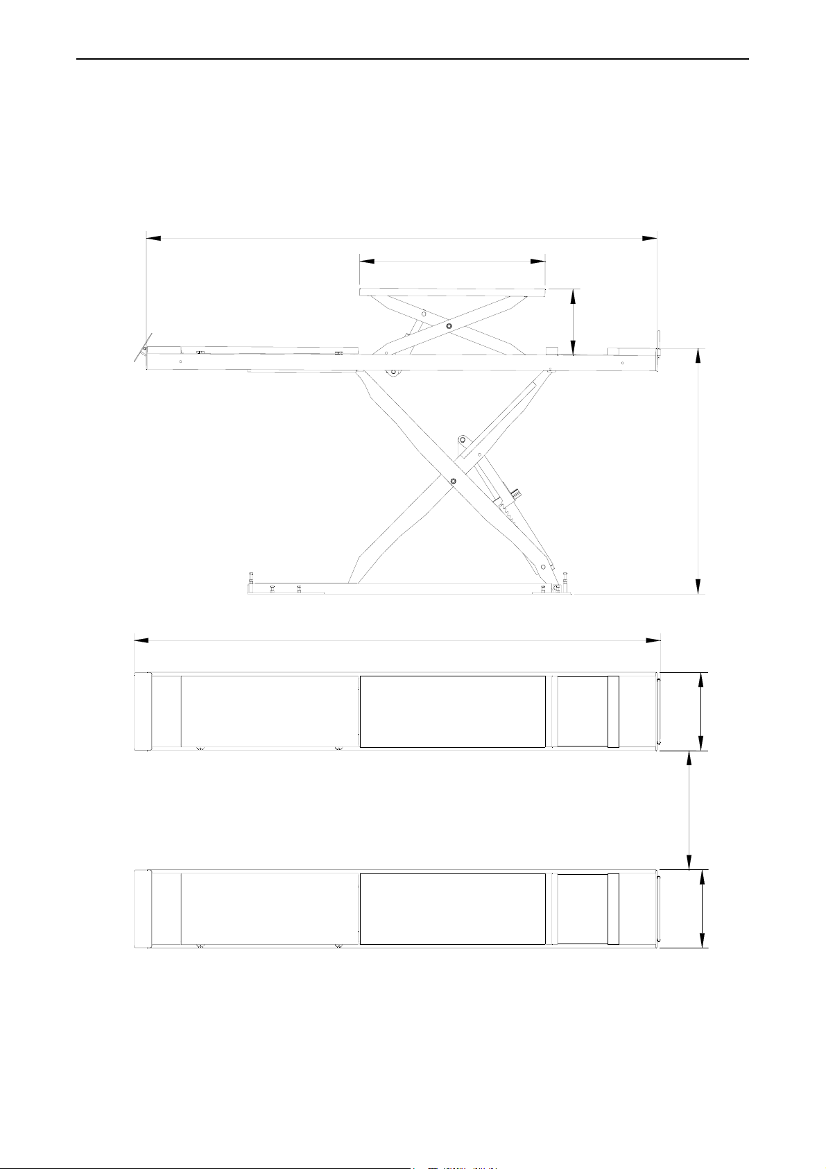
3.1 Structure
4500
1400
≥450
4660
330-1850
605
780
605
Fig1
3
Page 8
LAUNCH TLT830WA Product Manual
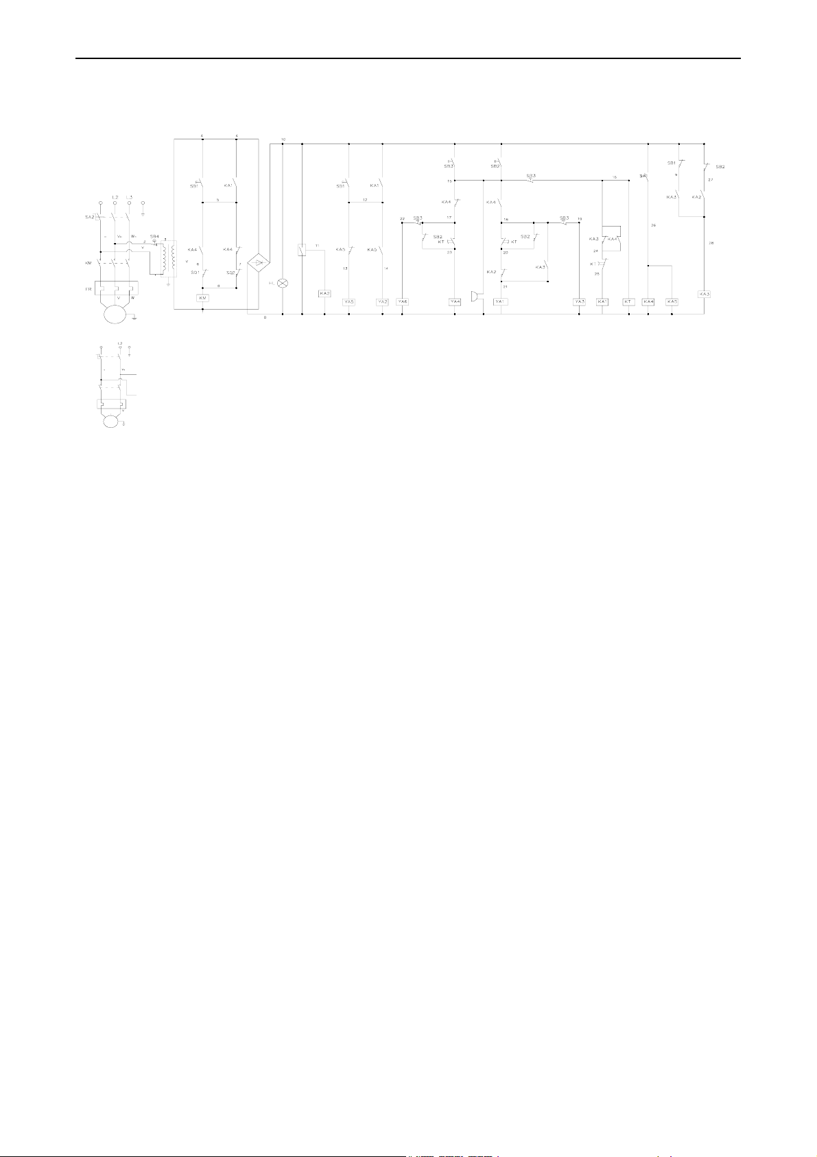
3.2 Electrical Diagram
AC200V/220V/380V
AC110V/220V 1PH
SA2
KM
FR
PEL1
U
U
M
3~
T
~
380
PEL1
~
27
VD
H
lowering
electric
relay
Bidirectional
valve II
Bidirectional
valve I
smaller
cylinder
valve II
valve II
buzzer
lowering
valve I
small air
cylinder
valve I
electric
relay
time
relay
KM-contactor
U
1
~
220V
2
U
M
1~
H-buzzer
YA-electron magnetic valve
Fig 2
Big scissor lifting procedure: turn the switch(SA1)to“I”position,When the UP button SB1 is pressed
the contactor KM will close. The motor will drive the pump and send oil to the cylinder. Main two-way solenoid
valve YA2 coil pick-up, which will in turn raise the platform upward;Once the UP button SB1 is released,
contactor KM will be open and the power to the motor will be cut off to stop the platform. Keep pushing button
SB1; the platform will reach a position so that limit switch SQ1 is triggered. Then SQ will open to stop the
motor and the platform to protect the machine from damaged.
Safety procedure:Release button SB1 when the platform reaches a desired height and press SAFETY
LOCK button SB3 to actuate lowering solenoid valve YA1 and the safety ratchet will be engaged by lowering.
Before servicing the car, make sure the safety lock is functional.
Big scissor lower procedure:After service is completed, push the UP button SB2, time contactor KT and
contactor KM will close. The motor will drive the pump to send oil to the cylinder, Main two-way solenoid
valve YA2 coil pick-up, which will in turn push the platform upward 2 seconds (adjustable) to release the safety
ratchet. Meanwhile small YA3 air cylinder valve electrical connection is established, the safety cover is fully
open. After 2 seconds contactor KT will open. The motor and the platform will stop. And at the same time,
lowering solenoid valve YA1 begins to work so that the platform will start to go down (See Figure 2)
Small scissor lifting procedure:turn the switch to “II” position,When the UP button SB1 is pressed the
contactor KM will close. Auxiliary two-way solenoid valve YA5 coil pick-up,which will in turn raise the platform
upward;Once the UP button SB1 is released, contactor KM will be open and the power to the motor will be cut
off to stop the platform. Keep pushing button SB1; the platform will reach a position so that limit switch SQ1 is
triggered. Then SQ will open to stop the motor and the platform to protect the machine from damaged.
Safety procedure:Release button SB1 when the platform reaches a desired height and press SAFETY
LOCK button SB3 to actuate lowering solenoid valve YA4 and the safety ratchet will be engaged by lowering.
Before servicing the car, make sure the safety lock is functional.
Small scissor lowering procedure:Push the UP button SB2, time contactor KT and contactor KM will close.
The motor will drive the pump to send oil to the cylinder, auxiliary two-way solenoid valve YA5 coil pick-up,
which will in turn push the platform upward 2 seconds (adjustable) to release the safety ratchet. Meanwhile
small YA6 air cylinder valve electrical connection is established, the safety cover is fully open. After 2 seconds
contactor KT will open. The motor and the platform will stop. And at the same time, lowering solenoid valve
YA4 begins to work so that the platform will start to go down (See Figure 2).
Stop procedure: Press stop button SB4 when needed.
4
Page 9
LAUNCH TLT830WA Product Manual
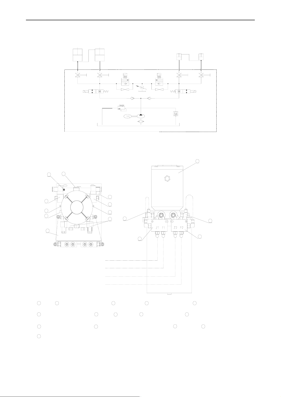
3.2 Hydraulic Diagram
Z1 Z2F1 F2
PP
11
11
10
12
1111
10
8
1
9
5
4
1
7
9
7
3
2
Fig3
3.3 Hydraulic Components in Control Desk
Top view
15
8
2
12
13
7
9
11
10
3
8
6
1
6
14
5
4
NO.1(Z1)
NO.2(F1)
NO.3(Z2)
NO.4(F2)
motor
1
6
Small scissors oil interface
11
bigscissor emergency lowering
handle
System pressure control valve
15
NO.1(Z1):big scissor main cylinders hydraulic tubing
NO.2(F1):big scissor offside cylinders hydraulic tubing
big scissor control solenoid
2
valve
7
Oil cap
bismall scissor emergency lowering handle
12
big scissor oil
3
interface
Exhaust Oil
8
Port
big scissor high pressure
Small scissors and high
4
pressure cut-off valve
Small scissor control
9
5
cut-off valve
check valve
10
solenoid valve
13
Speed control
tank(Oil capacity:15L)
14
valves
NO.3(Z2):small scissor main cylinders hydraulic tubing
NO.4(F2):small scissor offside cylinders hydraulic tubing
Fig 4
Under normal working conditions, the main cycle of the combined valve 5 is open, while the subsidiary
5
Page 10
LAUNCH TLT830WA Product Manual
cycle is closed. Small scissor main high pressure valve 4 is opened, deputy valve is turned off (to open valve
counterclockwise, clockwise to turn off) If lifting hydraulic system failure or power outage, need to use the Jack
to move the insurance top gear, chocked with object to avoid insurance teeth meshing in the descent, then
rotate emergency back-port 12 to lowering the Small scissor lift. Then rotate emergency back-port 11 to
lowering the big scissor lift. System for lowering speed can be adjusted by adjusting the throttle valve 13.
During the adjustment process and adding oil, the operator should be careful.
Hydraulic oil leveling:
To fill oil to slave cylinder of the big scissor, open the deputy valve and close main high-pressure valve 5,
then push the big scissor's up button to filling and adjusting. If too much oil is added, press the DOWN button
to discharge oil to ensure the two platforms at same height. To fill oil to slave cylinder of the small scissor, open
the deputy valve and close main high-pressure valve 4, then push the small scissor's up button to filling and
adjusting. If too much oil is added, press the DOWN button to discharge oil to ensure the two platforms at
same height. After finishing the adjustment, open the main cycle and turn the subsidiary off.(see fig4)
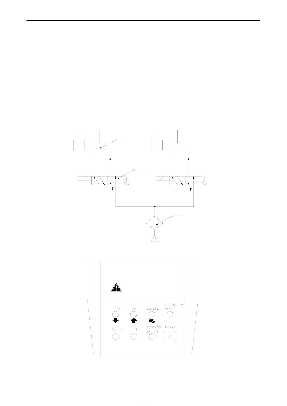
3.4 Pneumatic Diagram
Cylinder
3.5 Operation description
Valve
Air source
TLT830WA
Attention:
Pay attention to balance during up and down。
Note things around when lowering the lift。
Safety locking device is engaged,in this case staff allowed work
under the car。
Filter
Fig 5
6
Page 11

LAUNCH TLT830WA Product Manual
4 Installation and commissioning and Unpacking
4.1 Please get the following tools ready for installation:
Tools Specifications
Level Bar L=400(15.7″)
Chalk Line 10mm (0.4″)
Taper Plunger Chip
Hammer 1.5 kg (3 lb)
Crescent Wrench 40mm(1.6″)
Open end Wrench Set 11mm-23mm(0.43″-0.9″)
Allen Wrench Set 2mm~12mm
Screwdriver 150mm(5.9″)
Rotary Hammer Drill 20mm(0.8″)
Hard Alloy Drill Bit Φ19mm(0.75″)
Frame Level(JB3239-83) L*W*H=300x40x300(11.8″x 0.16″x 11.8″)
4.2 Unpacking
The lift is delivered in three separate boxes: 2 platforms (with hydraulic hoses) and 1 control desk.
Unpack according to the instructions on the packages. Remove the packing materials and check for
damage and loss of components.
To avoid accidents from occurring, keep the packing material away from children. The packing materials
need to be disposed of properly if they may contaminate the environment.
5. Equipment installation
5.1 Basic requirements
y The lift can only be installed on concrete floor with a minimal thickness of 200mm(7.9″),and at least
7 days of solidification time.
y The strength of the concrete ground should exceed 3000PSI(2.1kgf/mm2)。
y The tolerance of the concrete floor levelness should not exceed 5mm(0.2″)。Slight slope can be
corrected with shims. Excessive slope on the ground will greatly affect the performance of the lift. In
this case, new concrete slab should be made.
y Inspect for possible hindrance such as low ceiling, overhead pipelines in the work area, passageways
and escapes. The working area of the lift should be 4.2M(165.4″)high to give enough space.
y Allow enough space(at least 2M(78.7″)) at the front and back of the lift so that operation should not
be hindered. (see fig6)
y Power supply: Put the power source in place before installation. All the wiring should be performed by a
qualified electrician.
5.2 Installation Procedures
5.2.1 Tunnel Installation
Tunnel positioning mode is the same as the normal positioning, but tunnel positioning is more difficult
than the usual ones because to avoid cars slipping, the hanging plates hidden component need to be
replaced. Tunnel size see fig 6, normally only few people install the lift without the hanging plates hidden
7
Page 12

LAUNCH TLT830WA Product Manual
component in the tunnel. Location of tunnel floor dimensions refer to figure 7
Warnings:
♦ The depth of the pits should over 200mm,The strength of the concrete ground should
be great than 3000PSI(2.1kg/mm2),and the tolerance of the concrete floor levelness
should not exceed 5mm(0.2″)。
♦ Use the lifting equipment to put the host and vice machine into the pit
400Min
wall
1800Max
φ 100
20
2000Min
°
5
4
780670 670
900
330
800Min
4600
480
Fig 6
5.2.2 Above floor installation
♦ Equipment installation shown in figure 7,total width with 2530 mm ( 99.6 '' ), draw two
parallel lines on top of the concrete slab ( 1# and 2# ), error in 3mm ( 0.1 in ).
♦ And then draw the four parallel lines ( A, B, C, D ), and 1# and 2# perpendicular to the
line
♦ According to figure 7 put the host and auxiliary machines in the wireframe
8
Page 13

LAUNCH TLT830WA Product Manual
Master
1
.
7
6
2
car direction
3
1
6
-
φ
2
0
1998
543
480
2585
Fig 7
Attention:
♦ All dimensions are based on outer boundary of the base plate.
♦ Ensure that the overall error control within 6mm(0.24″)
♦ Draw a layout is very important. If not, problems will arise in the final assembly and
operation
5.2.3 Control Desk Installation
z According to the situation on the ground to determine the positions of electronic control boxes and
determine power supply requirements for local use, according to the diagram requirements
Slave
1565 235
25
549
599 800
z Wiring diagram shown in figure 8.
z After opening the side door of electronic control box, connect the limit switch cable to terminals (5,7)
on the big scissor, connect the limit switch cable to terminals (6,7)on the small scissor. Then use
4x2.5mm2 wire (Supplied by the customers themselves) respectively to connect the terminals L1, L2, L3,
PE. Check the correct connection before let the power on; open the control box to turn on the power
switch, now the power indicator light on the operator panel is on.
9
Page 14

LAUNCH TLT830WA Product Manual
z Requirements for the lifting machine control box installed near the power control switch, for maintenance
and emergency cut off power supply circuit. Electrical components damage due to error wire connection is
not covered by warranty.
z Oil Injection capacity as required. Do not start the motor without oil
z Fill hydraulic oil N32 or N46 (approximate 20L) into the oil tank (using oil gauge to check the level). Pay
special attention to avoid dust and contaminants into the oil.
z After hoses are assembled, press up button to check power system. If motor does not run, or gets
abnormal noise, or motor runs but lift does not go up or motor heats up. The power must be cut off and
check the wiring connection.
PE
T
~
380
~
27
VD
H
~
electric
relay
23
lowering
valve
II
Bi directional
valve
II
lowering
valve
I
22
small
air
cylinder
valve
II
Bi directional
valve I
small
air
cylinder
valve
I
141921
Bi directional
valve I
0
smaller
cylinder
valve
II
13
Optical
switch
Bi directional
valve II
switch
II
lowering
valve
II
607811
buzzer lowering
limit
switch
Ilimit
valve I
small
air
cylinder
valve I
electric
relay
time
relay
Fig 8
Notice:
High Voltage inside the control desk! Wiring should be performed carefully
5.2.4 Hydraulic Hose Connection
z TLT835WA Hydraulic pipeline as shown in figure 9。To inject hydraulic oil into the tank in accordance with
the requirements and capacities, then connect the hydraulic hose Z1 to hydraulic pipe fitting Z1 inside
the control box and tighten the fitting, Check the status of the combined valve. (Main cycle is opened and
the subsidiary is closed.)
z Press UP button,Test power supply unit:If the motor does not run, abnormal noise, the motor is running
but the table does not raise abnormal motor heat. At this point should be immediately shut down and
check the electrical connections are correct
z Press UP button, raise the host platform to 1.5 m (59') high, press the safety lock button, makes
machinery insurance work
10
Page 15

LAUNCH TLT830WA Product Manual
z Follow the wiring diagrams connect the hydraulic hose F1 to hydraulic pipe fitting F1 inside the control box,
the same, connect hose Z2 and F2 to hydraulic pipe fitting Z2 and F2 and tighten the fitting
Small scissort master cylinder
big scissor offside cylinder
Small scissor offside cylinder
big scissort master cylinder
NO.1(Z1)
NO.2(F1)
NO.3(Z2)
NO.4(F2)
T-fitting
pump
station
YJF
Fig 9
z Turn off the main high pressure cut-off valve on the big scissor, open the duty high pressure cut-off valve,
Press UP button, raise the auxiliary platform to 1.5 m (59') high, press the lowering button, makes
machinery insurance work. Requires host and auxiliary safety gear meshing at the same height position
so that the small scissor can be adjusted.
z Press UP button,raise the host platform of the small scissor to 0.35M(13.8″)high,Turn off the main
high pressure cut-off valve on the big scissor, open the duty high pressure cut-off valve,Press UP button,
raise the auxiliary platform to the same height. Turn the main and auxiliary high pressure valve to a
working state
z The oil pipe in the machine should be installed reliably and securely, avoid squeezing the pipe when the
machine is lowering Cause damage to the pipe affect the normal use of the device
z Turn the main and auxiliary high pressure valve to a working state after all the oil pipe have been
installed.
z For surface mounting, after piping connected to the slot cover plate must be installed
5.2.5 Anchoring
z Wrap the oil fittings, cable connections and joints of the lift to prevent dusts from getting in.
z With the help of the holes on the base plate, drill and install the anchor bolts. In the process of drilling,
make sure that there is no movement at the base frames. Fasten the base frames of the lift to the pits with
11
Page 16

LAUNCH TLT830WA Product Manual
drilling
clean
fastening
16 M16x160mm(M0.63″x6.3″) anchor bolts(Fig.11)
z Rotate adjustment screws on the base plate; adjust the plat until they are leveled.
And the host and auxiliary table height difference is not greater than 3mm(0.1″)。Choose the right thickness
of steel plate as a gasket (accessories) put it under the base plate; gasket should be inserted with both sides
of expansion bolts.
z Tighten out the nuts to fix the base frames on the pits.
z If installed on the ground, then follow the steps above to install anchor bolts of the approach plate.
M16x160mm(M0.63"x6.3")
150
φ22
expanding
Fig 10
Cautions:
z To ensure safety and performance, follow the installation procedures step by step.
z Wear safety goggles。
z Use strong alloy drill bit with a diameter of 17mm(0.7″). Do not use worn-out drill bit
z Keep the hammer drill upright with the surface of the hole.
z Keep hammer drill going by itself. Do not apply extra pressure.
z The depth of the hole depends on the length of the bolt. It is advisable that the bolts above the base
frames should be around 30mm. (1.2″)
z Remove the dust from the holes.
z Tap the bolt into the hole, insert and hit the core until the bolt fully expands
z Tighten out the bolts with torque wrench with a capacity of 80N.M
5.2.6 Air Hose Connection
z Connect the hoses according to the pneumatic diagram
z Keep the output pressure of the air source at 5kg/cm2.
z Press down button to check if the air cylinder acts correctly. If not, please check the hose connection.
12
Page 17

LAUNCH TLT830WA Product Manual
6 Operation
6.1 Inspection before operation
z Check for the synchronized and steady movement of the platforms.
z Check the sensibility and reliability of safety ratchet.
z Review the platforms reach the highest position ( 1850mm 72.8 ), the platform will automatically stop
rising
z Check if two small platforms up and down movement is consistent and smooth
z Check when small platforms rose to the highest position(450mm 17.7″),whether the platform is
automatically stopped rising
z View cylinders, tubing and connectors with or without leakage
z Check solenoid valve, air cylinder, pressure - regulating valve, connector has no leakage phenomenon
z Check the motor, gear pump operation sound is normal
z Check the slide plate for proper action
z Check the emergency stop button is working correctly
6.2 Operational Procedures
z Vehicle into the lift machine speed should be kept under 5km/h, confirm that the slide latch plates are
plugged in.
z When the vehicle is stopped, the front wheel is located at the centre of the turn plates, pull your hand
brakes
z Press the up button, rise the vehicle to 200mm~300mm (7.9″~11.8″)
z Check whether the vehicles and lifting machine level and have no abnormal state。
z Continue pressing the up button, to lift the vehicle up to its required height。
z Press the lock button,bring down the platform, safety gear meshing and keep the platform level on both
sides
z Press the small scissors lift button to remove the tire
z Check there are no foreign objects around or below the lift before start to repair and maintain the vehicle,
make sure there is no abnormal state and then press the down button; lowering down to the initial
position.
6.3 Safety Precautions
z The hydraulic relief valves are well-adjusted before leaving factory. The manufacturer will not be
responsible for any damage caused by unauthorized adjustment.
z Check the safety lock ratchets are engaged before going about any under-car jobs
z Before the small scissors lift the vehicle up, suitable pad must be selected. Place rubber pads on the
platforms and spread them for maximal support.。
z In case of any leakage in the hydraulic system, fix the problem and refill the oil to the proper level.
z When you press the lock button,after the safety gear on both side meshing,immediately release the
button,otherwise the cylinder back oil will be too much. After the completion, press the lowering button
(big scissor), circuit settings for the cylinder cannot supply enough oil to make the platform rise to
disengage the safety gear. At this point, platform could not be descended or only one side of safety gear
disengaged, and the other side still engaged, which leads to only one platform descended, and the
vehicle will rollover. (See hydraulic schematic diagram)
13
Page 18

LAUNCH TLT830WA Product Manual
7 Adjusting
7.1 Preparations
z Move the contact surface of in roller filling in 2# lithium grease, from left to right scrolling surface evenly.
z Add 2# lithium grease at the joints of the machines.
z Fill up the tank with hydraulic Oil N32 or N46(Depending on the season and the local temperature)
7.2 Adjustment Procedures
z Check if all the connection bolts are tightly fastened
z If there is air in hydraulic system due to new installation, air bleeding performance is needed. The air in
the master cylinder can be bled after the platform goes up and down several times. The air in the slave
cylinder can be bled out by following steps: lift master platform close to the maximal height; adjust the
main high-pressure valve until it is turned off, open the deputy valve; press the UP button to raise the
slave platform reaches near the maximal height, press the DOWN button to lower slave platform to the
bottom. Repeat three more times, all the air in the slave cylinder can be bled after the operation.
z Adjust the amount of auxiliary engine oil, to let the platforms stop at appropriate height。
z Turn the high-pressure valve to working status.
z Press UP button, the platforms begin to raise, release the UP button, the platforms stop moving. Press
the safety lock button, scissor lock down. Then, press the DOWN button, the platforms will raise a little to
disengage to safety claw, meanwhile the safety cop is opened, lift will be lowered.
z The same operation on the small platform.
z Adjust position of the mounting plate equipped with a limit switch make sure the platforms up to the
proper height, limit switch is triggered, pumping station stop working; cutting off cylinder oil, platform stop
rising and thus play a role in protecting the machine.
Notice:
z Attention should be paid to the position of oil pipes and hydraulic hose when the platforms move to the
minimal height for the first time. Make sure they do not get stuck with platforms moving downwards.
z When bleeding the air in the slave cylinder, do not lift Master Platform to the maximal height. Otherwise,
the limit switch is triggered, the power will be cut off and Slave Platform can't move.
z When bleeding the air in the slave cylinder lift Slave Platform to highest position, and then release the UP
button. Otherwise Oil pressure may damage the hydraulic cylinder
14
Page 19

LAUNCH TLT830WA Product Manual
8 Parts List
This parts list is only to be used by maintenance and servicing personnel.
The manufacturer is not responsible in case it is used for any other purposes.
If any parts get damaged, please order from your dealer or Launch Tech.
15
Page 20

LAUNCH TLT830WA Product Manual
8.1 Host Assembly
No ERP Code Name
1
2
3
4
5
307041275
307041276
307041277
307041278
307041279
HG-DJ-2000-22 Side board weldi ng pa rt
HG-DJ-2000-5 Roller pad
HG-DJ-9000B Main connecting rod
HG-DJ-9000A Vice connecting rod
Offside cylinder for auxiliary machinery
16
Page 21

LAUNCH TLT830WA Product Manual
6
7
8
9
10
11
12
13
14
15
16
17
18
19
307041280
307041281
307041282
307041283
307041284
103050035
103050014
307041285
307041286
307041287
307041288
307040756
307041289
307041290
HG-DJ-9000A-9 Rolling bridge jack wheel
HG-DJ-9000C Rolling bridge jack welded cover
HG-DJ-2000-24 Cushion blocks for turn table
HG-DJ-2000-26 Block
HG-DJ-4000-2 Twisted axis for auxiliary machinery
GB894.1-86 Circlip for shaft A 25
GB894.1-86 Circlip for shaft A 30
HG-DJ-4000-8 Cylinder hinge axis for auxiliary machinery
HG-DJ-4000-7 Cylinder hinge axis for auxiliary machinery
HG-DJ-4000-3 Center shaft for auxiliary machinery
HG-DJ-4000-11 Shim B
GB/T889.1-20001 Hexagon flange lock nut; M24
HG-DJ-2000-25 Guide block
HG-GSDJ-5000-27 Slide rack assembly(With core rivet)
20
21
22
23
24
25
26
27
28
29
30
31
32
33
307040763
103010356
307041291
307041292
103020096
103030127
307040817
307041293
307041294
307041295
103010156
103010423
307041296
103010469
JB/T7940.4-1995 Seal oil cup 8
GB/T70.1-2000 Screw M8×16
GB/T97.1-2002 Flat Washer A 8×1.6
GB/T859-1987 Spring washer 8×1.6
GB/T70.1-2000 Screw M8×30
GB/T41-20001 Nut C M8
Limit switch
HG-DJ-2000-30 Limit switch frame for rolling jack
GB/T859-1987 Spring washer 4×0.8
GB/T6170-20001 Nut A&B M4
GB/T818-2000 Screw M4×30
GB/T818-2000 Screw M4×6
GB/T97.1-2002 Flat Washer A 4×0.8
GB/T77-2000 Screw M8×12
34
35
36
37
38
39
307041297
307040760
307041298
307041299
307041300
307041301
Slide bolt
SSA20-15
GB/T818-2000 Screw M5×20
GB/T97.1-2002 Flat Washer A 5×1
GB/T859-1987 Spring washer 5×1.1
HG-4635DJ-5000-26 Sideslip spring
17
Page 22

LAUNCH TLT830WA Product Manual
40
41
42
43
44
45
46
47
48
49
50
51
52
103260099
103200699
103260114
103010313
307041302
307041303
307041304
307041305
103050025
103010435
307041306
307041307
307041308
Non-lubricated bearing SF-2 2528
Non-lubricated bearing SF-2 2520
Non-lubricated bearing SF-2 3020
GB/T70.1-2000 Screw M6×25
HG-DJ-2001A Main girder 4.5
HG-DJ-2000-36 Front pipe
HG-DJ-7000-00 Welded baffle plate 4.5
HG-DJ-7000-05 Stop plate shaft
GB894.1-86 Circlip A 20×1
GB/T818-2000 Screw M5×30
GB/T889.1-20001 Hexagon flange lock nu t M5
HG-DJ-2000-29 Sliding block
HG-DJ-4000-12 Shim C
18
Page 23

LAUNCH TLT830WA Product Manual
No ERP Code Name
1
2
3
4
5
6
7
8
9
10
307041309
307041310
307041311
307041312
307041313
307041314
307041315
307041288
307040756
307041316
HG-DJ-1000B Main connecting rod
HG-DJ-1000A Slave connecting rod
HG-DJ-4000-14 Lower block
HG-DJ-4000-13 Upper bloc k
Non-lubricated bearing SF-2 3467
HG-DJ-11000-4 W elding safety catch for host machine
HG-DJ-4000-4 Center shaft for host machine
HG-DJ-4000-11 Shim B
GB/T889.1-20001 Hexagon flange lock nu t M24
HG-DJ-4000-1 Hinge axis for host machine
19
Page 24

LAUNCH TLT830WA Product Manual
11
12
13
14
15
16
17
18
19
20
21
22
23
24
307041317
307041318
307041089
103260104
103260108
307040763
307041319
307041320
103010313
307041321
307041322
307041323
103010425
307041324
HG-DJ-4000-5 Cylinder hinge axis
HG-DJ-4000-6 Hinge axis for rod
SSA32-30 Master air cylinder
Non-lubricated bearing SF-2 3040
Non-lubricated bearing SF-2 3025
JB/T7940.4-1995 Seal oil cup 8
JB/T7940.2-1995 Joint grease Cup M8X1
GB/T12-1988 Bolt M6×16
GB/T70.1-2000 Screw M6×25
GB/T97.1-2002 Flat Washer A 6×1.6
GB/T859-1987 Spring washer 6×1.3
Non-lubricated bearing SF-2 3625
GB/T818-2000 Screw M4×10
Master cylinder
25
26
27
28
29
30
31
32
33
34
35
36
37
38
307041325
103010437
103050014
307040790
307040791
307041326
307041327
103010505
307041328
103030131
307040802
103020081
307041329
307041291
Pipe clasp
GB/T818-2000 Screw M6×10
GB894.1-86 Circlip for shaft A 30
GB894.2-86 Circlip for shaft B 34
GB894.2-86 Circlip for shaft B36
HG-DJ-11000A Square tube welding for master cylinder
HG-DJ-3000 Integral base
Anchor bolt M16X150
HG-DJ-3000-1 1 L o wer fri ct i o n pad
GB/T41-20001Nut C M16
GB/T5781-2000 Thread C M16×50
GB/T5781-2000 Thread C M16×80
GB/T70.1-2000 Screw M8×8
GB/T97.1-2002 Flat Washer A 8×1.6
20
Page 25

LAUNCH TLT830WA Product Manual
8.2 Auxiliary engine assembly
No ERP Code Name
1
2
3
4
5
6
307041330
307041276
307041277
307041278
307041331
307041280
HG-DJ-2000 Auxiliary crossbeam 4.5
HG-DJ-2000-5 Roller pad
HG-DJ-9000B Master connecting rod for host machine
HG-DJ-9000A Vice connecting rod for auxiliary machinery
Main cylinder for auxiliary machinery
HG-DJ-9000A-9 Rolling bridge jack wheel
21
Page 26

LAUNCH TLT830WA Product Manual
7
8
9
10
11
12
13
14
15
16
17
18
19
20
307041282
307041283
307041284
103050035
103050014
307041285
307041286
307041287
307041288
307040756
307041289
103010313
307041290
307040763
HG-DJ-2000-24 Cushion blocks for turn table
HG-DJ-2000-26 Block
HG-DJ-4000-2 Twisted axis for auxiliary machinery
GB894.1-86 Circlip for shaft A 25
GB894.1-86 Circlip for shaft A 30
HG-DJ-4000-8 Cylinder hinge axis for auxiliary machinery
HG-DJ-4000-7 Cylinder hinge axis for auxiliary machinery
HG-DJ-4000-3 Center shaft for auxiliary machinery
HG-DJ-4000-11 Shim B
GB/T889.1-20001 Hexagon flange lock nut M24
HG-DJ-2000-25 Guide block
GB/T70.1-2000 Screws M6×25
HG-GSDJ-5000-27 Slide rack assembly(With core rivet)
JB/T7940.4-1995 Seal oil cup 8
21
22
23
24
25
26
27
28
29
30
31
32
33
34
103010356
307041291
307041292
103020096
103030127
307040817
307041294
307041296
103010469
307041297
307040760
307041298
307041299
307041300
GB/T70.1-2000 Screws M8×16
GB/T97.1-2002 Flat Washer A 8×1.6
GB/T859-1987 Spring washer 8×1.6
GB/T70.1-2000 Screws M8×30
GB/T41-20001 Nut C M8
Limit switch
GB/T859-1987 Spring washer 4×0.8
GB/T97.1-2002 Flat Washer A 4×0.8
GB/T77-2000 Screws M8×12
Slide bolt
SSA20-15
GB/T818-2000 Screws M5×20
GB/T97.1-2002 Flat Washer A 5×1
GB/T859-1987 Spring washer 5×1.1
35
36
37
38
39
40
307041304
307041303
307041305
103010435
307041306
103050025
HG-DJ-7000-00 Welded baffle plate 4.5
HG-DJ-2000-36 Front pipe
HG-DJ-7000-05 Stop plate shaft
GB/T818-2000 Screws M5×30
GB/T889.1-20001 Hexagon flange lock nu t M5
GB894.1-86 Circlip A 20×1
22
Page 27

LAUNCH TLT830WA Product Manual
41
42
43
44
45
46
47
48
49
50
51
307041301
103260099
103200699
103260114
103010423
307041275
307041281
307041332
103010377
307041307
307041308
HG-4635DJ-5000-26 Sideslip spring
Non-lubricated bearing SF-2 2528
Non-lubricated bearing SF-2 2520
Non-lubricated bearing SF-2 3020
GB/T818-2000 Screws M4×6
HG-DJ-2000-22 Side slide plate welding part
HG-DJ-9000C welded cover of rolling jack
Limit mounting plate
GB/T818-2000 Screws M4×16
HG-DJ-2000-29 Block
HG-DJ-4000-12 Shim C
No ERP Code Name
1
2
3
4
307041309
307041310
307041311
307041312
HG-DJ-1000B Main connecting rod
HG-DJ-1000A Vice connecting rod
HG-DJ-4000-14 Lower block
HG-DJ-4000-13 Upper bloc k
23
Page 28

LAUNCH TLT830WA Product Manual
5
6
7
8
9
10
11
12
13
14
15
16
17
18
307041333
307041314
307041315
307041288
307040756
307041316
307041317
307041318
307041089
103260104
103260108
307040763
307041319
307041320
HG-DJ-11000 Square tube welding for offside cylinder
HG-DJ-11000-4 Welding safety catch for host machine
HG-DJ-4000-4 Center shaft for host machine
HG-DJ-4000-11 Shim B
GB/T889.1-20001 Hexagon flange lock nut M24
HG-DJ-4000-1 Hinge axis for host machine
HG-DJ-4000-5 Cylinder hinge axis
HG-DJ-4000-6 Hinge axis for rod
SSA32-30 Master air cylinder
Non-lubricated bearing SF-2 3040
Non-lubricated bearing SF-2 3025
JB/T7940.4-1995 Seal oil cup 8
JB/T7940.2-1995 Joint grease cup M8X1
GB/T12-1988 Bolt M6×16
19
20
21
22
23
24
25
26
27
28
29
30
31
32
103010313
307041321
307041322
307041323
103010425
307041334
307041325
103010437
103050014
307040790
307040791
307041335
307041327
103010505
GB/T70.1-2000 Screws M6×25
GB/T97.1-2002 Flat Washer A 6×1.6
GB/T859-1987 Spring washer 6×1.3
Non-lubricated bearing SF-2 3625
GB/T818-2000 Screws M4×10
Non-lubricated bearing SF-2 3456
Pipe clasp
GB/T818-2000 Screws M6×10
GB894.1-86 Circlip for shaft A 30
GB894.2-86 Circlip for shaft B 34
GB894.2-86 Circlip for shaft B 36
offside cylinder
HG-DJ-3000 Integral base
Anchor bolt M16X150
33
34
35
36
37
38
307041328
103030131
307040802
103020081
307041329
307041291
HG-DJ-3000-11 Lower friction pad
GB/T41-20001 Nut C M16
GB/T5781-2000 Thread C M16×50
GB/T5781-2000 Thread C M16×80
GB/T70.1-2000 Screws M8×8
GB/T97.1-2002 Flat Washer A 8×1.6
24
Page 29

LAUNCH TLT830WA Product Manual
8.3 Distribution of hydraulic and pneumatic components
216
218
203
215
221
206
212
211
Distribution of hydraulic parts
No ERP Code Name
201
217
213
210
220
206
Power unit (380V50Hz three phase)
218
203
214
209
219
204
208
Power unit (220V50Hz single phase)
Power unit (220V60Hz three phase)
Power unit (220V60Hz single phase)
Power unit (200V60Hz three phase)
201
202
205
218
203
207
202
203
204
205
206
207
208
209
210
211
212
213
214
307041336
103040157
103100160
103202175
103040158
307041337
307041338
307041339
307041340
307041341
307041342
307041343
307041324
pe 0.5M high-pressure oil pipe
Pad assembly 14
Corner joint
Converting valve block
Pad assembly 16
C type bended 4.8M high-pressure oil pipe
C type 3.6M high-pressure oil pipe
C type bended 0.35M high-pressure oil pipe
C type bended 5.8M high-pressure oil pipe
C type bended 8.2M high-pressure oil pipe
C type bended 1.55M high-pressure oil pipe
C type bended 4.7M high-pressure oil pipe
Master cylinder for big scissor
25
Page 30

LAUNCH TLT830WA Product Manual
215
216
217
218
219
220
221
307041335
307041331
307041279
103100162
103990055
103100161
103160043
Offside cylinder for big scissor
Master cylinder for small scissor
Offside cylinder for small scissor
M14x1.5 Straight joint
T-fitting
Throttle joint components
Throttle valve
Distribution of pneumatic parts
No ERP Code Name
301
302
303
304
305
306
307
308
309
310
311
102160383 Two-linkage piece for air supply
102990071 Fitting APL6-02
102160380 T- Fitting APE6
102990066 Silencer
103200654
103160033 Electromagnetic valve 4V210-08-DC24V
103100073 Plug 1/4″
104990092 Air pipe PU0604
307041089 SSA32-30 Air cylinder
102990070 Fitting APL6-01
307040760 SSA Thin cylinder
Plug 1/8″
26
Page 31

LAUNCH TLT830WA Product Manual
407
413
402
401
8765
KA5
415
123
9101112
13144
2223
8765
KA4
408
123
8765
KA3
9101112
13144
TLT830WA
Attention:
Pay attention to balance during up and down。
Note things around when lowering the lift。
Safety locking device is engaged,in this case staff allowed work
under the car。
Down Up
Buzzer LED
406
008101113141921
0
0
1
123
123
8765
8765
KA2
KA1
9101112
9101112
13144
13144
Safety
transfer
switch
405
TC
AC
2
+
7
123
123
8765
KT
9101112
9101112
13144
13144
412
1110 12
403
404
emergency
stop
Power
414
20 21
L12 L21
W21 V21
L1L2 L3
PE
KM
L1L2 L3
PE
VUW
409
RD
410
A1A2
411
Distribution of electrical parts
No ERP Code Name
401
402
403
404
405
406
407
408
409
410
411
102100083 ButtonLA39-22/g
102100085 ButtonLA39-22/r
102100084 ButtonLA39-11/K
102100090 Emergency stop buttonLA39-11/r
307040820 Transformation buttonAPT-LA39
102990065 LED DC24V
103180018 Terminal
102130034 Transformer JCY5-100 220V,380V/27V
102150053 Fuse RT18-32
102110059 Contactor s-p11 AC24V
102110067 Time relay H3Y-2 DC24V 0-10S
416
418
417
412
413
414
415
102110051 intermediate relay MY4NJ DC24V
102270004 Rectifier KBPC25-10
102100087 Power switch LW39B-16
102140018 Buzzer
27
Page 32

LAUNCH TLT830WA Product Manual
416
417
418
102100121
307040818 Optical switch
limit switch 1
limit switch 2
9 Troubleshooting
Symptoms Reasons Solutions
The motor does not
work.
The motor works,
but the platforms do
not move, or can
only go up slowly.
Check the fuse and limit switch.
Voltage is not correct.
Electrical wiring is wrong.
Motor is broken.
The motor rotates in the wrong
direction.
Oil level is too low.
Height limit switch is stuck or
damaged.
Repair or change the fuse or limit switch.
Supply power of correct voltage.
Fix the wiring.
Change motor.
Exchange wiring of motor to change
direction.
Add oil.
Repair or replace the height limit switch.
The motor works,
but the platforms
can not lift the
vehicle.
The lift is too slow in
lowering.
The platforms are
not synchronized.
The voltage to the motor is too low.
Pressure of relief valve is not right.
The lift is overloaded
The hydraulic pump is damaged.
There is foreign substance in the
lowering solenoid valve.
Lowering speed valve is turned too
low.
There is air in upper chamber of
Master Cylinder or Slave Cylinder.
The oil supply can't be cut off because
of the leakage of stop valve.
Leakage in hydraulic system
The air pressure regulating valve is
Supply motor with correct voltage.
Adjust the pressure of relief valve.
Check the weight of the vehicle.
Replace the hydraulic pump.
Clean the lowering solenoid valve.
Turn the lowering speed valve up.
Air bleeding performance is needed. The
air in the master and slave cylinder can be
bled after the platform goes up and down
several times.
Replace stop valve.
Replace the seal or the cylinder.
Adjust air pressure to 5kg/cm2
Safety ratchets
cannot be separated
from serration.
closed or too low.
The Solenoid air valve is damaged.
The LOCK button is pressed for too
long time.
28
Replace the solenoid air valve.
Release the LOCK button immediately after
the safety ratchets are fully engaged.
Page 33

LAUNCH TLT830WA Product Manual
10 Maintenance
10.1 Daily Maintenance
z Keep the lift clean. Make sure power is cut off before cleaning the lift.
z Keep the working area clean. Excessive dust in the work area will shorten the lifespan of the lift.
z Before operation, inspect and keep all the safety devices of lift in order. If any problems are found, adjust, maintain or
replace the parts timely.
z Make sure that the pits are kept dry and clean.
z Inspect if there is leakage in the air valve and if it is well-lubricated.
10.2 Monthly Maintenance
z Refasten the anchor bolts.
z Check all the hoses and fittings for possible wearing and leakage. If any leakage is found to be caused by worn sealing
parts, replace with parts meeting the specifications.
z Check if the roller slide is well-lubricated with high-quality #2 lithium lubricant.
z Apply #2 lithium lubricants on a monthly basis.
10.3 Biannual Maintenance
z Check all the moving parts for possible wearing, interference and damage.
z Inspect the lubrication of all the rollers. If the roller is dragged along in lifting or lowering, apply lubricant to the roller
shaft.
z At the end of the first six months, clean the hydraulic system and replace the hydraulic oil. Replace the hydraulic oil
with N32 hydraulic oil in winter and N46 in summer.
10.4 Maintenance for 3 Years or 5000 Times Operations
z Replace the bushings at all joints.
z Replace all seals
z Replace the rollers.
11 Storage and Scrapping
11.1 Storage
When the lift needs to be stored for a long time:
z Unplug from power socket.
z Lubricate all the parts, including all the contact surface of the rollers.
z Bleed oil from tanks.
z Cover the lift with plastic hood.
11.2 Scrapping
When the lift has exceeded its lifespan and can not be used any more, disconnect it from the electrical supply and dispose of
as required by the local regulations.
29
Page 34

LAUNCH TLT830WA Product Manual
TLT830WA Hydraulic Oil Data
#2 Lithium Lubricants
Item
Conical degree(1/10mm)
Dropping point ℃
Erosion(T2 Copper Plate,100 ℃,24h)
Copper Screening(100℃,22h)% 4
Evaporation(100℃,22h)% 2
Oxidizing Stability(99℃,100 h) 0.2
Non-corrosibility(52℃,48) Grade 1
Foreign substance(Microscopic method)/
(number/cm³)
Above 10µm
Above 25µm
Above 75µm
Above 125µm
Specifications
278
185
No Change
5000
3000
500
0
Relative Viscosity
(-15℃,10s-1 ),/(Pa·s)
Less than
Humidity Loss(38℃,1h)(%)
less than
N32 Mechanic Oil (for winter)
Item
Moving Viscosity 40℃
Pour / ℃ ≤-15
Flash point / ℃ ≥175
N46 Mechanical Oil (for summer)
Item
Moving Viscosity 40℃
Pour / ℃ ≤-9
Flash point / ℃ ≥185
800
8
Specifications
28.8~35
Specifications
41.4~50.6
30
 Loading...