

Page 1

LAUNCH TLT632AF INSTALLATION MANUAL
1
INSTALLATION MANUAL
Contents
1 Precautions……………………………………….2
2 Structure and Working Principle……….….....3
2.1 Structure…….…………………………………...3
2.2 Electrical Diagram……………………………...4
2.3 Hydraulic Diagram………….....…………….....5
2.4 Hydraulic Components in Control Desk……...5
2.5 Pneumatic Diagram……………………….……6
3 Tools …………….……………………...…………7
4 Unpacking………………………………..……….7
5 Installation………………………….…….……….7
5.1 Basic Requirements……….……………………7
5.2 Installation Procedures……….…………...…..7
5.2.1 Base Frame Installation……….…….….…..7
5.2.2 Control Desk Installation….……….….…….8
5.2.3 Hydraulic Hose Connection…………...…....9
5.2.4 Anchoring ………..…………..……...……....10
5.2.5 Air Hose Connection…………………….…..12
6 Adjustment……………..………..…..……….….11
6.1 Preparations….……………………..……..……11
6.2 Adjustment Procedures………………...….…..11
7 Safety Rules for Electrical Control System.. 12
8 Parts List………………….………..……..……....13
Drawing of hydraulic system………………………..13
Page 2
LAUNCH TLT632AF INSTALLATION MANUAL
2
1 Precautions
Warnings
Please read and understand the manual before
operation
This manual is an important part of the product.
Please read and understand it thoroughly.
Keep the manual for future use in inspection and
maintenance.
Do not use the product for any other purposes.
The manufacturer is not responsible for any damage
caused by improper use or uses other than the
designed purpose.
Precautions for Installation and
Adjustment
Please read this manual and operation manual in full
before installation and adjustment. Any changes to
the components or use for other purpose without the
consent of the manufacturer may lead to direct or
indirect damage to the product.
Installation and adjustment personnel should have an
understanding of electronic equipment.
Never allow untrained personnel to operate the lift.
Allow sufficient space for the lift so that operation
should not be hindered.
Do not install the lift in an environment with extreme
temperature and humidity conditions. Keep it away
from heating device, faucet, humidifier or furnace.
Do not install the lift outdoors or expose it to rain. If
it is really necessary to do so, a special order should
be made from the manufacturer.
Check the components against parts list before
installation. In case of any questions, please
contact your dealer or Launch Tech.
For the sake of technical improvements, Launch
(Shanghai) Machinery Co., Ltd reserves the right to
change the specifications without prior notice.
Page 3
LAUNCH TLT632AF INSTALLATION MANUAL
3
2 Structure and Working
Principle
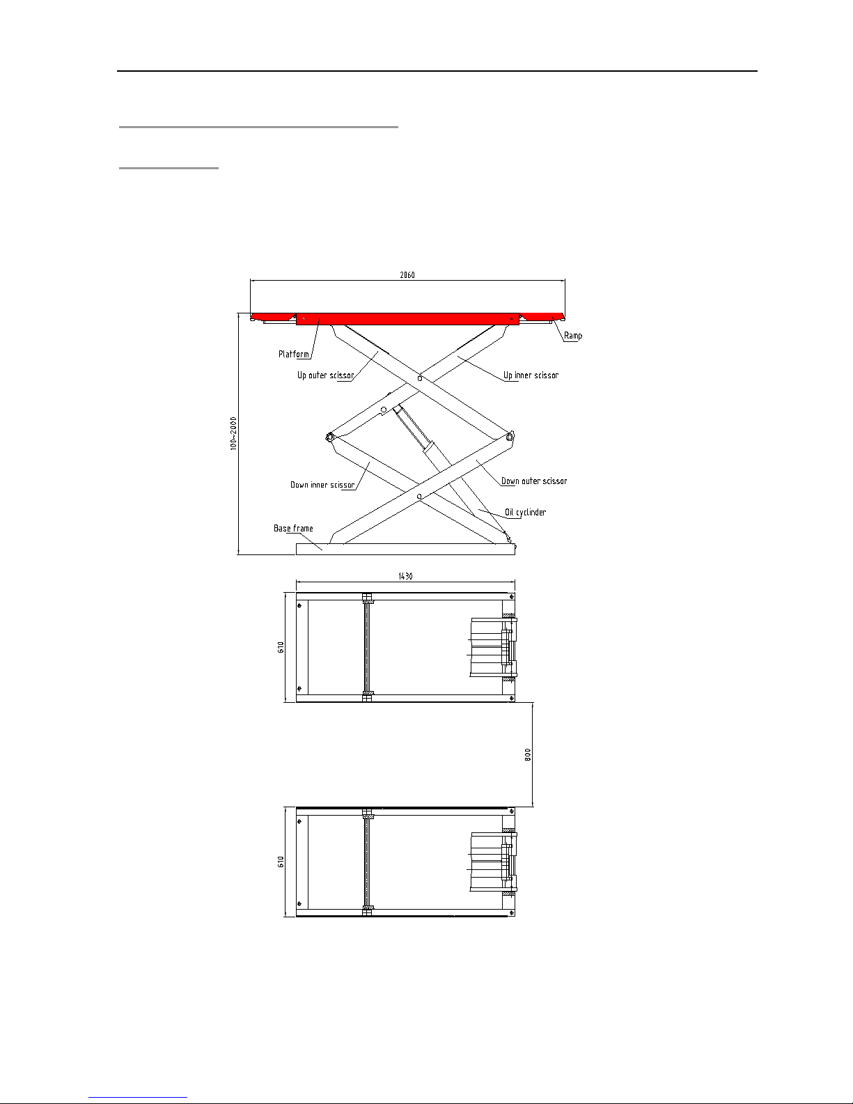
2.1 Structure
Fig.1
Page 4
LAUNCH TLT632AF INSTALLATION MANUAL
4
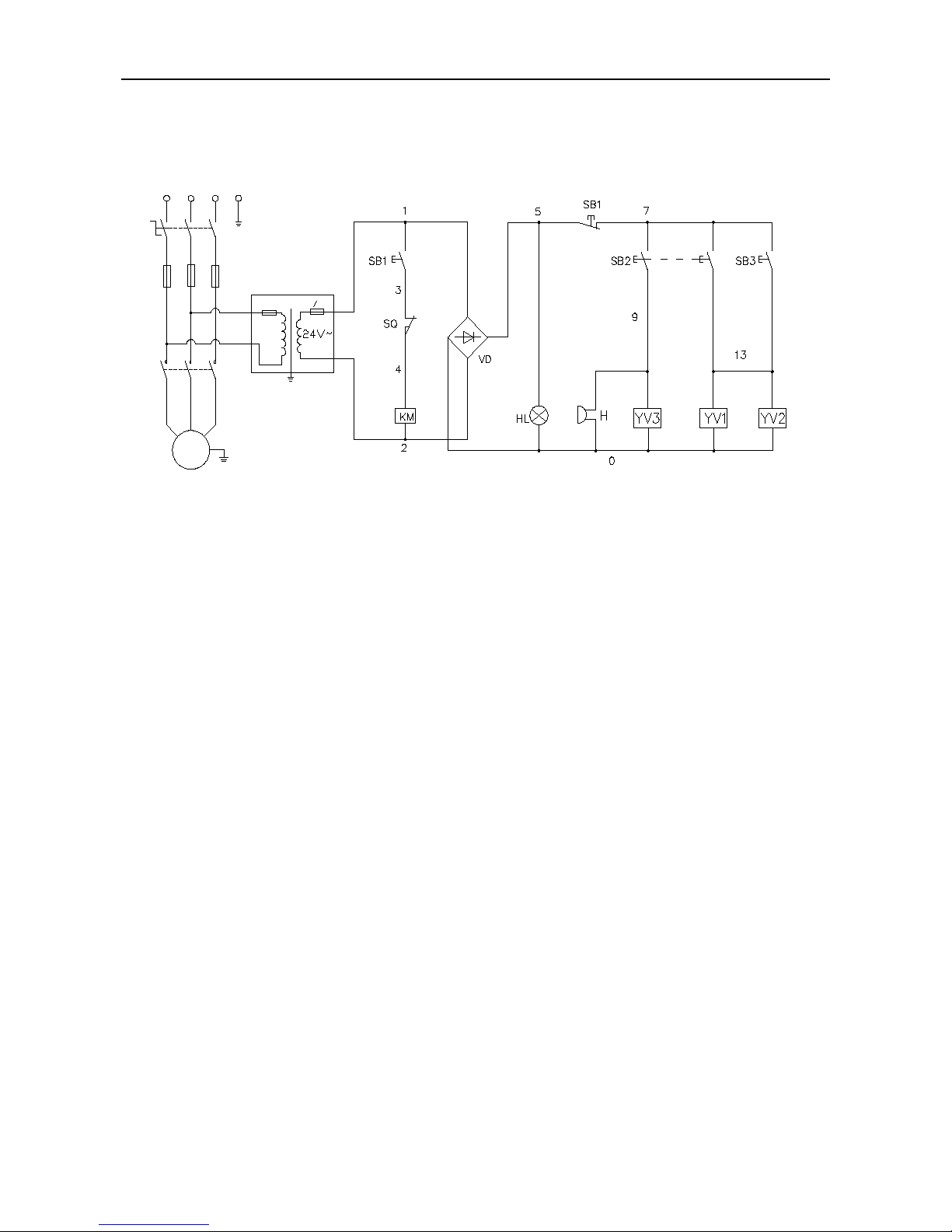
2.2 Electrical Diagram
W
U
V
M
3~
V
21
U
21
W
21
QC
KM
PEL1 L2 L3
T
AC220V/380V 3PH
V
11
U
11
W
11
FU1
FU2/(0.5A
)
FU3 (3A
)
Fig.2
Lifting process: Press UP button SB1, The motor will
drive the pump and send oil to the cylinder, which will in turn
raise the platform upward. Release button SB1, the platform
will stop rise. Keep pushing button SB1, when the platform
reaches at the Max. height, release valve will be activated
and protect the lift.
Safety Locking process: press Safety button SB3,
solenoid valve YV1, YV2 will be engaged, the safety system
is locked.
Lowering process: Press UP button SB1, platform rise
a little, safety device is unlocked, then press DOWN button
SB2, solenoid valve YV1, YV2, YV3 will be engaged, the
platform begin to lower.
Page 5

LAUNCH TLT632AF INSTALLATION MANUAL
5
2.3 Hydraulic Diagram
1
2
3
4
5
6
7
7
8
8
9
9
10
10
P
11
Z1 Z2F2 F1
Fig.3
2.4 Hydraulic Components in Control Desk
Fig.4
F2 Z2 Z1 F1
Page 6

LAUNCH TLT632AF INSTALLATION MANUAL
6
Under normal working conditions, equalization valves (8)
and emergency lowering valves (9) are closed. Oil flows to
the lower chamber of master cylinder through check valve
and the force of the piston causes the oil in the upper
chamber of the master cylinder to flow to the slave cylinder,
so the two platforms go up equally. The flow of oil from check
valve to the slave cylinder is blocked by equalization valves
(8).
For emergency lowering, open 2 emergency lowering valves
(9) to lower the lift sl owly and carefully. The lowering speed
can be adjusted by speed valve (11).
To equalize two platforms, open 2 equalization valves (8),
raise the lift up and down 1 or 2 times and firmly closed
valves (8).
2.5 Hydraulic Components in Control Desk
8
2
6
4
7
5
3
1
9
Fig.5
3 Tools
Please get the following tools
ready for installation:
Tools
Specifications
Level Bar L=400mm(15.7″)
Chalk Line
10mm(0.4″)
Taper Plunger Chip
Hammer
1.5 kg(3 lb)
Crescent Wrench 40mm(1.6″)
Open end Wrench Set
11mm-23mm(0.43
″
-0.9″)
Allen Wrench Set
2mm-12mm
Screwdriver 150mm(5.9″)
Rotary Hammer Drill
20mm(0.8″)
Hard Alloy Drill Bit
Φ17mm(0.7″)
Frame Level(JB3239-83) L*W*H = 300mm ×
40mm× 300mm(11.8″
×
0.16″×11.8″)
Page 7

LAUNCH TLT632AF INSTALLATION MANUAL
7
4 Unpacking
The lift is delivered in one package: 2 platforms
(with hydraulic hoses) and 1 control desk connected
together.
Unpack according to the instructions on the
packages. Remove the packing materials and
check for damage and loss of components.
To avoid accidents from occurring, keep the packing
material away from children. The packing materials
need to be disposed of properly if they may
contaminate the environment.
5 Installation
5.1 Basic Requirements
Fig.6
The lift can only be installed on concrete floor with a
minimal thickness of 200mm(7.9”) and at least 7
days of solidification time.
The strength of the concrete ground should exceed
3000PSI (2.1kgf/mm
2
)
The tolerance of the concrete floor levelness should
not exceed 5mm (0.2”). Slight slope can be
corrected with shims. Excessive slope on the
ground will greatly affect the performance of the lift.
In this case, new concrete slab should be made.
Inspect for possible hindrance such as low ceiling,
overhead pipelines in the work area, passageways
and escapes. The working area of the lift should be
4.2m(165.4”) high to give enough space.
Allow enough space (1.5m/59”) at the front and back
and left and right of the lift so that operation should
not be hindered.
Power supply: Put the power source in place before
installation. All the wiring should be performed by a
qualified electrician.
It is default installation, the control unit could be
installed at the right side of lift as well. The
installation should be performed by qualified people.
5.2 Base Frame Installation
Fig.7
Layout plan: Refer to the Total width 2020mm (79.5”),
Page 8

LAUNCH TLT632AF INSTALLATION MANUAL
8
drawing two parallel lines (1# and 2#) on the
concrete floor, the tolerance should less than 3mm
(0.1”).
Draw four parallel lines (a, b, c, d), vertical with 1#
and 2#.
Follow the drawing, put two platforms into the frame.
Warnings:
The base is the edge of Floor plate.
The tolerance should less than 6mm (0.24”)
Drawing the frame is very important. Poor drawing will
cause many problems about assembly and operation.
5.3 Control Desk Installation
Place the control desk in place according to the
ground layout.(Fig.6)
Use cover plate to protect the wires if there is no
wire channel on the concrete floor.
Fill hydraulic oil N32 or N46 (approximate 20L) into
he oil tank (using oil dipstick to check the level).
Pay special attention to avoid dust and contaminants
into the oil.
Page 9

LAUNCH TLT632AF INSTALLATION MANUAL
9
5.4 Power supply connection
Open the control desk, connect the wires according
to the electrical diagram. After check the connection,
switch on the power. Turn on the power supply
switch which is on the panel of control desk. The
indict light will turn on.
Power switch is needed, and installed near control
desk. Cut the power when maintenance or
emergency. The damage which is caused by wrong
wire connection is not covered by warranty.
Make sure the oil level is above the standard level.
DO NOT operate the lift if oil tank is empty.
Fix all the oil hoses and press UP button, test the
electrical parts: if motor does not operate, abnormal
sound, platform does not rise, motor is hot, STOP
operating immediately and check the wire
connection.
Fig.8
Notice:
High voltage in control desk, ground lead must be safe.
8 leters oil is needed in the first use, fill the oil and make
sure the oil level is above the standard level.
5.5 Anchoring
Wrap the oil fittings, cable connections and joints of
the lift to prevent dusts from getting in.
Raise the platforms to 1.5m, then install the anchor
bolts.
With the help of the holes on the base plate, drill and
install the anchor bolts. In the process of drilling,
make sure that there is no movement at the base
frames. Fasten the base frames of the lift to the
pits with 8 M16*120(M0.63″X4.7″) anchor bolts.
Rotate the adjusting bolts, adjust the platform to
same level, the equalization should less than 3mm
(0.1”). Choose a right shim and place it under frame.
Insert the shims at both sides of anchor bolt.
Tighten out the nuts to fix the base frames on the
floor.
Cautions: To ensure safety and performance, follow the
installation procedures step by step.
Wear safety goggles.
Use strong alloy drill bit with a diameter of 18mm
(0.71″). Do not use worn-out drill bit.
Keep the hammer drill upright with the surface of the
hole.
Keep hammer drill going by itself. Do not apply
extra pressure.
Control Panel
1
5
3
7
7
9
7
13
Mother Board
7
13
9
Page 10

LAUNCH TLT632AF INSTALLATION MANUAL
10
The depth of the hole depends on the length of the
bolt. It is advisable that the bolts above the base
frames should be around 30mm (1.2”).
Remove the dust from the holes.
Tap the bolt into the hole, insert and hit the core until
the bolt fully expands
Fig.9
6 Adjustment
6.1 Preparation
Lubricate the moving surface of the roller with #2
lithium lubricant. Lubricant should be applied
evenly from left to right.
Lubricate the joints of the lifts with #2 lithium
lubricant.
Check the oil tank for enough hydraulic oil.
6.2 Adjustment Procedures
Check if all the connection bolts are tightly fastened.
Press UP button, the platforms are raising; release
the UP button, the platforms stop raising. Press
DOWN button, the platforms are lowering.
If there is air in hydraulic system due to new
installation, air bleeding performance is needed.
The air in the master cylinder can be bled after the
platform goes up and down several times. The air
in the slave cylinder can be bled by following steps:
lift Master Platform close to the maximal height;
unscrew the two exhaust screws severally. Screw
the exhaust screw when the all the air are ejected.
Refer to Fig.4 and cylinder adjustment, adjust the
platforms to the same level.
Notice:
Attention should be paid to the position of oil pipes and
hydraulic hose when the platforms move to the minimal
height for the first time. Make sure they don not get stuck
with platforms moving downwards.
When bleeding the air in the cylinders, can NOT unscrew
the two exhaust screws at the same time or operate the lift
when the exhaust screws are unscrewing.
7. Safety Rules for Electrical
Control System
1. Only personnel who are properly trained and have
adequate knowledge and skill should undertake all
electrical/electronic troubleshooting and repair.
2. Do not alter or bypass protective interlocks.
3. Before starting, read and observe all warning labels.
4. When trouble shooting make sure the power source has
been disconnected and main switch has been locked.
5. Take extra precautions in damp areas to protect you from
accidental grounding.
6. Before applying power to any equipment it must be
established, without a doubt, that all persons are clear.
7. Do not open the electrical control panel unless it is
necessary to check the electrical equipment.
8. Do not alter the electrical circuits unless authorized to do
so by the manufacturer.
9. When replacing electrical components, make sure they
conform to the manufacturer’s specifications, including
proper color coding.
Page 11

LAUNCH TLT632AF INSTALLATION MANUAL
11
10. Do not wear metal frame glasses, metallic necklaces or
chains while working on any electrical equipment. Also do
not wear any ring, watch or bracelet while operating
electrical equipment.
8 Parts List
This parts list is only to be used by maintenance and servicing personnel.
The manufacturer is not responsible in case it is used for any other purposes.
If any parts get damaged, please order from your dealer or Launch Tech.
Page 12

LAUNCH TLT632AF INSTALLATION
MANUAL
12
NO.
ERP CODE
NAME
1
201021438
Base frame 2 103202084
Down inner scissor assembly
3
201021503
Scissor bracket
4 104991231
Slide block
5
103202086
Long axle
6
201021497
Scissor bracket
7
103202087
Connecting axle 8 103202088
Connecting axle I 9 103202091
Connecting long axle
10 201021436
Scissor bracket
11
201021434
Scissor bracket
12
103202092
Supporting axle
13
202010118
Axle bushing
14
103202093
Block axle
15
202010119
Sliding block
16 201021437
Platform
17
104991230
Supporting block
18
201021502
Platform
19
201021439
Supporting bracket
20
Y201013184D
Connecting axle
21
103202061
Spring
22
103202063
Cylinder assembly
23
103202062
Cylinder assembly
24 103202085
Cylinder axle
25
201013178
Safety stick
26 103202089
Axle
27
103202090
Cylinder axle
28 103202095
Roller axle
29
201021498
Arm bracket
30
103200865
Roller
31
201013176
Arm bushing
32
201013181
Safety bushing II
33
201013180
Safety bushing I
34
201013179
Safety bushing III
35
201021500
Safety chain
36
103202097
Safety claw
37
201021499
Safety assembly
38
103202083
Air cylinder assembly
39
103100291
Y fitting
Page 13

LAUNCH TLT632AF INSTALLATION
MANUAL
13
40
201013188
Cylinder cover
41
Y201013055D
Scissor cover
42
103260111
Axle cover 2020
43
103260106
Axle cover 2525
44
103260195
Axle cover 2025
45
103260108
Axle cover 3025
46
103260194
Axle cover 2825
Hydraulic diagram
NO
ERP CODE
NAME
101 103260191
C type 4M end high pressure oil hose
102
103260190
C type bending head 3.5M high pressure oil hose
103
103260188
C type 2M high pressure oil hose
104
103260189
C type bending head 2.5M high pressure oil hose
105
103260193
C type 0.8M high pressure oil hose
106
103990055
T fitting
107
103260192 C type 2.5M end high pressure oil hose
108
103990185
Power unit assembly (380V/50Hz three phase)
103990188
Power unit assembly (220V/50Hz single phase)
103990187
Power unit assembly (200V/60Hz three phase)
103990186 Power unit assembly (110V/60Hz single phase)
103990190 Power unit assembly (220V/50Hz three phase)
Page 14

LAUNCH TLT632AF INSTALLATION
MANUAL
14
103990191 Power unit assembly (220V/60Hz three phase)
103990192 Power unit assembly (220V/60Hz single phase)
103990193 Power unit assembly (200V/60Hz single phase)
Page 15

LAUNCH TLT632AF INSTALLATION
MANUAL
15
Electrical diagram
NO.
ERP CODE
NAME
201
102130034
Transformer
202
102270004
Rectifier
203
103180018
Connecting board
204
102110059
Contactor
205
102150053
Fuse
206
102240039
Solenoid valve
207
102100137
Button
208
102100087
Power switch
209
102140018
Alarm
210
102990065
Indicating light
211
103160033
Solenoid air valve
212
102100135
Button
213
102100136
Button
Equipment record (6 pages) attached.
 Loading...