

Page 1

V1.00.000
2012-08-20
Page 2

LAUNCH KWB-511 Wheel Balancer user’s manual
i
Trademark Information
LAUNCH is a registered trademark of LAUNCH TECH. CO., LTD. (short for LAUNCH) in China and other
countries. All other LAUNCH trademarks, service marks, domain names, logos, and company names referred
to in this manual are either trademarks, registered trademarks, service marks, domain names, logos, company
names of or are otherwise the property of LAUNCH or its affiliates. In countries where any of the LAUNCH
trademarks, service marks, domain names, logos and company names are not registered, LAUNCH claims
other rights associated with unregistered trademarks, service marks, domain names, logos, and company
names. Other products or company names referred to in this manual may be trademarks of their respective
owners. You may not use any trademark, service mark, domain name, logo, or company name of LAUNCH or
any third party without permission from the owner of the applicable trademark, service mark, domain name,
logo, or company name. You may contact LAUNCH by visiting LAUNCH at http://www.cnlaunch.com, or
writing to Launch Industrial Park, North of Wuhe Rd., Banxuegang, Longgang, Shenzhen, Guangdong, P. R.
China, to request written permission to use Materials on this manual for purposes or for all other questions
relating to this manual.
Copyright Information
Copyright © 2012 by LAUNCH TECH. CO., LTD. All rights reserved. No part of this publication may be
reproduced, stored in a retrieval system, or transmitted in any form or by any means, electronic, mechanical,
photocopying, recording or otherwise, without the prior written permission of LAUNCH. The information
contained herein is designed only for the use of this unit. LAUNCH is not responsible for any use of this
information as applied to other units.
Neither LAUNCH nor its affiliates shall be liable to the purchaser of this unit or third parties for damages,
losses, costs, or expenses incurred by purchaser or third parties as a result of: accident, misuse, or abuse of
this unit, or unauthorized modifications, repairs, or alterations to this unit, or failure to strictly comply with
LAUNCH operating and maintenance instructions.
LAUNCH shall not be liable for any damages or problems arising from the use of any options or any
consumable products other than those designated as Original LAUNCH Products or LAUNCH Approved
Products by LAUNCH.
General Notice
Other product names used herein are for identification purposes only and may be trademarks of their
respective owners. LAUNCH disclaims any and all rights in those marks.
Page 3

LAUNCH KWB-511 Wheel Balancer user’s manual
ii
Information
Neither personal nor its affiliates shall be liable to the purchaser of this unit or third parties for damages, losses,
costs, or expenses incurred by purchaser or third parties as a result of: accident, misuse, or abuse of this unit,
or unauthorized modifications, repairs, or alterations to this unit, or failure to strictly comply with our company
operating and maintenance instructions.
Our company shall not be liable for any damages or problems arising from the use of any options or any
consumable products other than those designated as original our company products or approved products by
our company.
This manual instruction is suitable for wheel balancer KWB-511.
This unit is made for the purpose of persons who have special techniques and certifications.
Safety Instructions
z Make sure all operators are properly trained. Improper operations may result in incorrect measurement.
z Environments should conform to the regulations in this instruction manual.
z Keep the guard in working order.
z Transportation and operations should strictly follow the regulations in this manual; otherwise, the
manufacturer will not be responsible for the damage caused by improper transportation or operation.
z To use the equipment beyond its measurement range may cause damage to it and can not ensure precise
measurement.
z If operators violate safety regulations thus damage the machine by dismounting safety devices, the
manufacturer will immediately cease its safety promise.
Page 4

LAUNCH KWB-511 Wheel Balancer user’s manual
iii
Table of Contents
Product Instruction.....................................................................................................................................................................1
1 External Structural Drawing ..................................................................................................................................................1
2. Functions .............................................................................................................................................................................1
3. Specifications.......................................................................................................................................................................1
4. Packing List .........................................................................................................................................................................2
Control Unit.................................................................................................................................................................................4
Operating Instructions...............................................................................................................................................................5
1. Self-check ............................................................................................................................................................................5
2. Installing Wheel....................................................................................................................................................................5
3. Wheel Parameters Input ......................................................................................................................................................5
4. Choose balance modes .......................................................................................................................................................6
5. Standard Dynamic Mode .....................................................................................................................................................7
6. Static Mode..........................................................................................................................................................................7
7. ALU 1----ALU 3 Modes ........................................................................................................................................................8
8. ALU S Mode ........................................................................................................................................................................9
9. OPT Function.....................................................................................................................................................................11
10. Motorcycle Mode .............................................................................................................................................................12
Setting programs......................................................................................................................................................................13
1. System setting ...................................................................................................................................................................13
2. Calibration programs .........................................................................................................................................................14
Error Information and Treatment ............................................................................................................................................16
CE Declaration of Conformity..................................................................................................................................................17
Page 5
LAUNCH KWB-511 Wheel Balancer user’s manual
1
Product Instruction
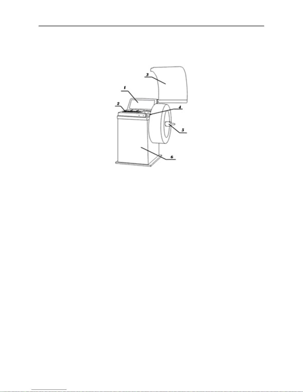
1 External Structural Drawing
Fig1
1.Operation Panel 2.Counterweight Container
3.Safety Guard 4.Mechanical sensor arm
5.Quick Lock Hub Nut 6.Balancer Body
2. Functions
z Dynamic Mode
z Static Mode
z Standard ALU1, ALU2, ALU3, Mode
z ALUS Mode
z OPT(OPTIMIZATION) mode
z Unit Conversion in Different Countries (Areas): g / oz, mm / inch
z Mechanical sensor arm
z Self-calibration
z Guard Protection
z Self-check Error and Diagnostics
3. Specifications
z Rated voltage: 110V /220V / 380V
z Protection Class: IP 54
z Motor power: 250w
z Max Rotating Speed: 220 r /min
z Cycle Time: Average 6-9s
Page 6
LAUNCH KWB-511 Wheel Balancer user’s manual
2
z Measurement Ranges:
Gauge length 10 --- 300mm
Rim Diameter: 10
” — 26”
Rim Width: 1.5” — 20”
z Error: ≤±1g 0.1 oz
z Noise: ≤70dB
z Net Weight: 95kg
z Gross Weight: 116kg
z Working Environment: Temperature: -20℃~50 , Humidity: ≤85%℃
z Package dimensions: 900×700×1170mm
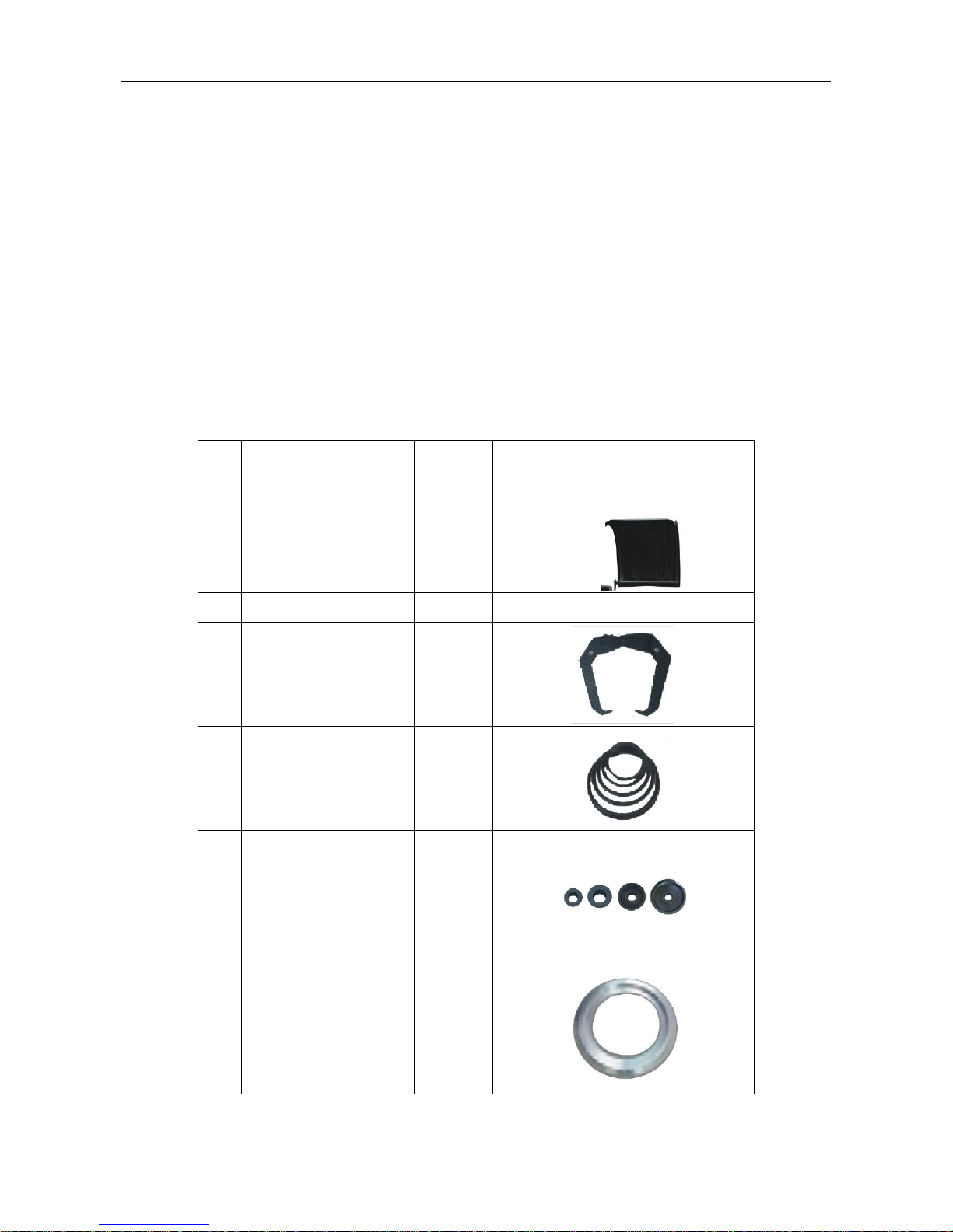
4. Packing List
SN Description Quantity Picture
1 Wheel Balancer 1set
2 Plastic protective cover 1 pc
3 Operation Manual 1 pc
4 Caliper 1 pc
5 Tower spring 1 pc
6 Cone 4 pc
7 Flange 1pc
Page 7
LAUNCH KWB-511 Wheel Balancer user’s manual
3
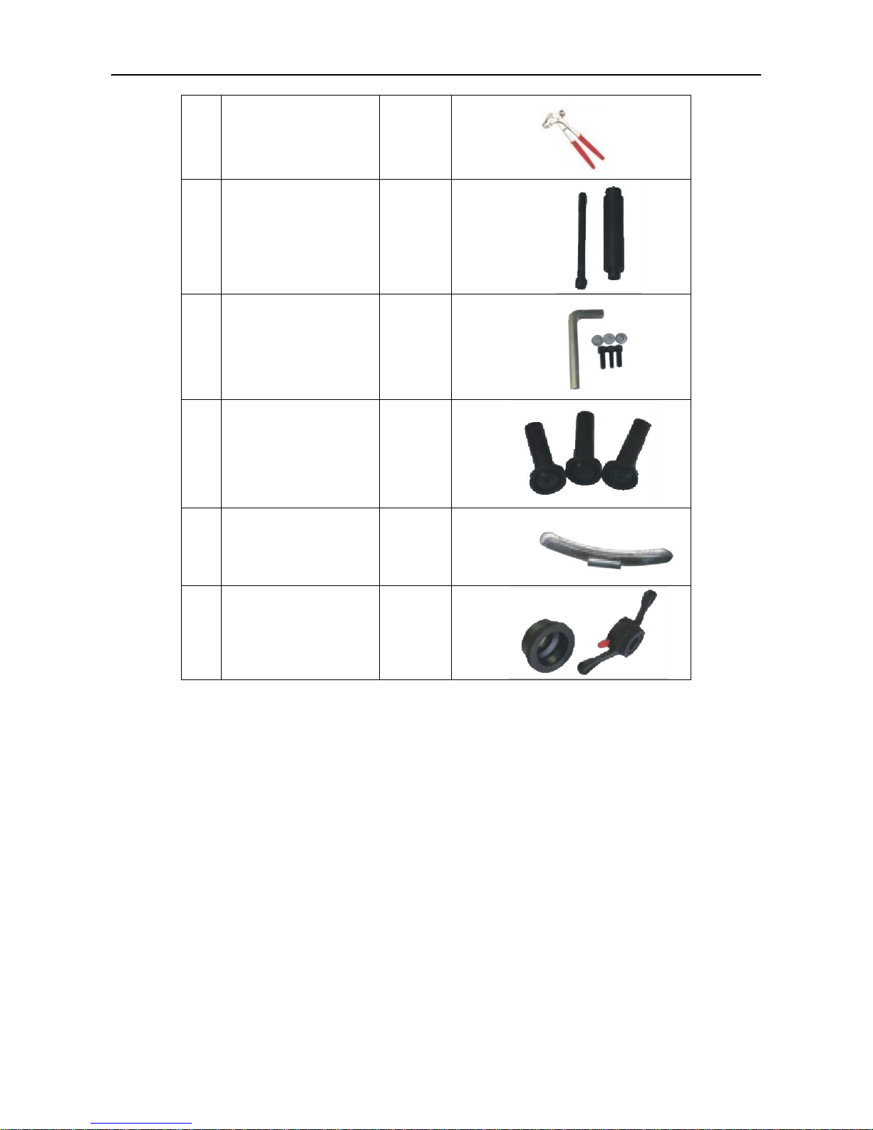
8 Pliers
1 pc
9 Thread and bolt 1kit
10 socket head wrench 1 kit
11 hanger 3 pc
12
Standard Weight
1 pc
13 Quick nut and bowl 1 kit
Page 8

LAUNCH KWB-511 Wheel Balancer user’s manual
4
Control Unit
Fig2
A. inside unbalance point B. inside unbalance display window
C. middle static unbalance display window D. sticking and clamping weight position indicator
E. outside unbalance display window F. outside unbalance point
G. standard dynamic mode indicator H. static mode indicator
I. ALU mode indicator J. ALUS mode indicator
K. OPT indicator L. mm/inch indicator
M. Motorcycle mode indicator . O. Size input shift key
P. function key Q. +function key
R. Enter key S. Dynamic/Static key
T. ALU mode key U. OPT key
V. Unit shift key W. START key
X. Motorcycle mode key Y. Fine display key
Z. STOP key
Page 9

LAUNCH KWB-511 Wheel Balancer user’s manual
5
Operating Instructions
1. Self-check
When switched on, the system begins self-check and then enters standard dynamic mode measurement (Refer to Fig3).
Fig3
2. Installing Wheel
Choose the optimal cone for the center hole and mount it on the balancer. (Refer to Fig4 and 5)
The method shown in figure 5 is preferable because it approximates to installing wheel on a real car.
Fig4 Fig5
3. Wheel Parameters Input
Unlike ALU S which needs 4 parameters, other modes need 3 parameters.
Parameter values are shown in Fig6 (dynamic and static modes, ALU 1-3 mode, motorcycle mode) and Fig7 (ALU S mode).
Users can finish the parameters input manually (Refer toFig8).
Note: Motorcycle tires automatic input parameters also need to install a dedicated extension rod. (Refer to Fig 18)
Fig6 Fig7
Page 10

LAUNCH KWB-511 Wheel Balancer user’s manual
6
Press
to choose parameter, and press to modify parameter value. After inputting the parameter press to
save and enter next parameter input state. In the state of D value input, press
to convert mm and inch.
4. Choose balance modes
The default mode of this equipment is standard dynamic mode. Choose other mode by pressing keys DYN/STA、ALU、MOT
(See Fig 9).
OPT mode can be operated by pressing the key OPT under dynamic and static modes.
Press STOP can stop measurement during measurement
Fig9
In ALUS mode
mm inch
Fig8
Page 11

LAUNCH KWB-511 Wheel Balancer user’s manual
7
5. Standard Dynamic Mode
This function is to test the amount of unbalance on the inside and outside of the rim while a wheel is rotating. Placing
counterweight on the tested position of both sides of the rim according to the displayed unbalance value can eliminate
unbalance.
First, choose standard dynamic mode, then install the Wheel and input parameters, after that follow the process of standard
dynamic operation in Fig10.
Or close the guard
Stop rotating measurement by opening the guard or
pressing STOP key in emergency
After correct input of
wheel parameters
Open the
guard
Measurement finished and the result is
displayed
Rotate the wheel,clamp a counterweight
of the displayed value(eg:70g)on the
outside correction position
Keep rotating,clamp a counterweight of
the displayed value (eg:40g) on the
inside correction position
Balancing finished
Fig10
The three values from left to right shown in Fig10 are unbalance value of the inside rim, static value and unbalance value of
the outside rim respectively. When the left and right unbalance values are 0 and the middle static value is more than 5g, then
by pressing FINE key the unbalance values less than 5g after standard dynamic balance will be displayed on the left and right
side of the screen. Now it is recommended to do static balance to achieve complete balance.
6. Static Mode
After dynamic mode measurement, you can select static mode directly. The balancer will automatically calculate the result of
static mode.
Page 12

LAUNCH KWB-511 Wheel Balancer user’s manual
8
Or first, choose static mode, then install the Wheel and input parameters, after that follow the process below.
Fig11
7. ALU 1----ALU 3 Modes
ALU1-3 mode refers to 3 counterweight sticking modes reduced according to the shapes and sizes of most rims. (Refer to
Fig12)
A special purpose gauge can be used to assist in sticking counterweights in Fig 13.
The measurement processes of ALU1-3 are the same as that of standard dynamic mode.
Fig12
19mm
3/4"
19mm
3/4"
19mm
3/4"
13mm
1/2"
13mm
1/2"
Fig13
Page 13

LAUNCH KWB-511 Wheel Balancer user’s manual
9
8. ALU S Mode
This mode can input the precise size of the correction plane with the aid of mechanical sensor arm. It compensates for
ALU1-3 and is more accurate than the traditional ALU mode. It is easier and faster to use as well.
Fig14
1) ALU S Correction Plane choosing
ALUS has to choose two proper correction planes on both sides of rim. Clean the position to be used to get ready for being
stuck.
2) ALU S Mode Operation
Mount the wheel and collect parameters. After collecting, close the guard, press START to measure. The process is the same
as that of standard dynamic mode.
See Fig15 for the outside sticking process. After measurement, rotate the wheel to the outside correction plane position
according to the figure. The position is calculated automatically by the parameters collected by mechanical sensor arm, so the
real correction position is not necessarily at 12 o’clock, in this case, locate the position with the mechanical sensor arm
The inside sticking process is shown in Fig16.
Page 14

LAUNCH KWB-511 Wheel Balancer user’s manual
10
Fig15
Page 15

LAUNCH KWB-511 Wheel Balancer user’s manual
11
40Cr
Left and right were
displayed inside and
outside of the imbalance
value ALU
Rotate the wheel, when it comes
to the inside correction position,
the outside display window
twinkles to show the distance
between the correction position
and the sensor arm tip
Pull the sensor arm and stick
the counterweight on the
exact”0" distance position
shown on the outside display
window
Medial end of lead paste
Fig16
Note: The KWB-511 mechanical sensor arm can only locate the 12 o’clock position, it will return to the measurement
interface if at any other position. So it is better to locate it at 12 o’clock and do the following operation.
9. OPT Function
OPT function is used to determine the best mating of tire and rim. When doing dynamic and static modes, if the static
mode value is greater than OPT value (implied 30g), then it’s better to start optimization.
When optimization is asked, press
key to operate according to the following table. When optimization is not needed,
display “OFFOPT” and exit OPT operation.
Page 16

LAUNCH KWB-511 Wheel Balancer user’s manual
12
Press OPT key to start
Step1
Rotate the gas nozzle to 12 o’clock.
Press ENTER key to memorize the point .Mark with a chalk a
reference mark on the tire
Step2
Remove the wheel from the balancer using a tire changer. Align
the nozzle and the mark by rotating the tire on the rim by 180
degrees.
Step3
Replace the wheel on the balancer and rotate the gas nozzle to 12
o’clock again. Press “ENTER” key to memorize
Step4
Press START key to start OPT measurement.
After measurement, mark with chalk again on the tire the marked
point indicated on the screen.
Using the changer to assemble until the new mark and the gas
nozzle coincide. Now the value displayed is the rest value after
optimization .On this point add 10g counterweight.
Press ENTER to end optimization
10. Motorcycle Mode
Motorcycle mode is the same as standard dynamic mode except that it needs special motorcycle fixtures and extending arms.
Page 17

LAUNCH KWB-511 Wheel Balancer user’s manual
13
Fig17
Fig18
Setting programs
1. System setting
System setting (refer to Fig19) is used to set options, such as the application control state, the commonly used units of this
equipment and so on.
Ways to enter: In any mode, press SET to enter.
Page 18

LAUNCH KWB-511 Wheel Balancer user’s manual
14
Fig19
2. Calibration programs
It is used to initialize the new machine and remove the old equipments’ measurement errors caused by total loss from use,
parts ageing and replacing, or strong impact.
Calibration procedures include unbalance calibration.
Press
or key to exit calibration program.
Choose a wheel with small unbalanced value and install it on the balancer. Input the wheel parameters then calibrate it as
shown in Fig20.
Page 19

LAUNCH KWB-511 Wheel Balancer user’s manual
15
End return correction
Press go to next step
Press the button,
into the calibration procedure.
Press start unbalance
correction
Press calibration of rotation
for the first time
End rotation, prompt placing a
counterweight of 100g at 12 o'clock
outside of rim.
Press calibration of rotation
for the second time
Press complete correction of
unbalance
End rotation, prompt placing a
counterweight of 100g at 12 o'clock
inside of rim.
End correction, automatic storage
calibration results and return to the
original state.
Fig20
Page 20

LAUNCH KWB-511 Wheel Balancer user’s manual
16
Error Information and Treatment
It provides the error diagnostics and prompting information of this equipment. Users can judge and deal with problems
according to the prompting information and the solutions given in the following form.
prompting information meaning of the information solutions
CCC CCC The result of measurement is beyond the
range.
OFF OFF System gives the prompt when the STOP key
is interrupted accidentally
Err 01 When the guard is set enabled, press START
key without closing it or open the guard
artificially while the wheel is in rotating
measurement. In either of these two cases,
the balancer gives the prompt
Close the guard, or turn off the
guard function option in setting
items. However, because the laws
and regulations of safety protection
in different countries are not
completely the same, we suggest
not turning off the guard function
option.
Err 02 Prompt is given and measurement is stopped
when rotating speed is too low to meet the
basic measurement needs,
Problems of the electrical motor
shaft or the transmission belts.
Check and adjust.
Too light load also results in this
phenomenon, so please adjust the
load weight.
Err 03 The measurement rotation is in wrong
direction. This usually will appear in the
three-phase motor control balancer due to
sequence errors
Adjust the sequence of the
three-phase power.
ERR 10 Gauge error Turn off the machine, return the
gauge to position 0, and then restart
it. If the error still exists, calibrate
the gauge following “Calibration
programs”
ERR CAL The machine is not calibrated. Users calibrate the machine
following “Setting programs”
ERS CAL Factory maintenance error. Contact the manufacturer.
Page 21

LAUNCH KWB-511 Wheel Balancer user’s manual
17
CE Declaration of Conformity
Page 22

LAUNCH KWB-511 Wheel Balancer user’s manual
18
Warranty
THIS WARRANTY IS EXPRESSLY LIMITED TO PERSONS
WHO PURCHASE LAUNCH PRODUCTS FOR PURPOSES
OF RESALE OR USE IN THE ORDINARY COURSE OF THE
BUYER’S BUSINESS.
LAUNCH electronic product is warranted against defects in
materials and workmanship for one year (12 months) from date
of delivery to the user. This warranty does not cover any part
that has been abused, altered, used for a purpose other than
for which it was intended, or used in a manner inconsistent with
instructions regarding use. The exclusive remedy for any
automotive meter found to be defective is repair or replacement,
and LAUNCH shall not be liable for any consequential or
incidental damages. Final determination of defects shall be
made by LAUNCH in accordance with procedures established
by LAUNCH. No agent, employee, or representative of
LAUNCH has any authority to bind LAUNCH to any affirmation,
representation, or warranty concerning LAUNCH automotive
meters, except as stated herein.
Disclaimer
THE ABOVE WARRANTY IS IN LIEU OF ANY OTHER
WARRANTY, EXPRESSED OR IMPLIED, INCLUDING ANY
WARRANTY OF MERCHANTABILITY OR FITNESS FOR A
PARTICULAR PURPOSE.
Order Information
Replaceable and optional parts can be ordered directly from
your LAUNCH authorized tool supplier. Your order should
include the following information:
1. Quantity
2. Part number
3. Item description
Customer Service
If you have any questions on the operation of the unit,
please call: 86-755-84528767.
If your unit requires repair service, return it to the
manufacturer with a copy of the sales receipt and a note
describing the problem. If the unit is determined to be in
warranty, it will be repaired or replaced at no charge. If
the unit is determined to be out of warranty, it will be
repaired for a nominal service charge plus return freight.
Send the unit pre-paid to:
Attn: Overseas Department
LAUNCH TECH. CO., LTD.
Launch Industrial Park,
North of Wuhe Rd.,
Banxuegang, Longgang,
Shenzhen, Guangdong, P. R. China.
 Loading...