

Page 1

Lathem Time Corporatio
n
Page 2

.
WARNING
www.lathem.com
(800) 241-4990
This equipment has been tested and found to comply with the limits for a Class A
digital device, pursuant to Part 15 of FCC Rules. These limits are designed to
provide reasonable protection against harmful interference when the equipment
is operated in a commercial environment. This equipment generates, uses, and
can radiate radio frequency energy and, if not installed and used in accordance
with the instruction manual, may cause harmful interference to radio
communications. Operation of this equipment in a residential area is likely to
cause harmful interference in which case the user will be required to correct the
interference at his or her own expense.
Caution: Changes or modifications not expressly approved by the party
responsible for compliance could void the user's authority to operate the
equipment.
THIS DIGITAL APPARATUS DOES NOT EXCEED THE CLASS A LIMITS FOR RADIO NOISE EMISSIONS
FROM DIGITAL APPARATUS AS SET OUT IN THE RADIO INTERFERENCE REGULATIONS OF THE
CANADIAN DEPARTMENT OF COMMUNICATIONS.
LE PRÉSENT APPAREIL NUMÉRIQUE N'ÉMET PAS DE BRUITS RADIOÉLECTRIQUES DÉPASSANT LES
LIMITES APPLICABLES AUX APPAREILS NUMÉRIQUES DE CLASSE A PRESCRITES DANS LE
RÈGLEMENT SUR LE BROUILLAGE RADIOÉLECTRIQUE ÉDICTÉ PAR LE MINISTÈRE DES
COMMUNICATIONS DU CANADA.
1.
The details of this User's Manual are subject to change even without previous notification.
2.
This User's Manual has been prepared with the utmost care to cover all aspects of the time
recorder's use.
3.
Be sure to use your time clock after you have fully understood the hardware and software
specifications and limits.
4.
No part of this publication may be reproduced, stored in a retrieval system, or transmitted,
in any form or by any means, mechanical, photocopying, recording or otherwise.
This User's Manual and its contents are copyrighted by LATHEM
TIME CORP. with all rights reserved
Page 3
PRECAUTIONS
This user's manual is prepared for safe and proper use of the unit.
Please follow all the instructions to avoid possible danger to yourself or
others and damage to the unit.
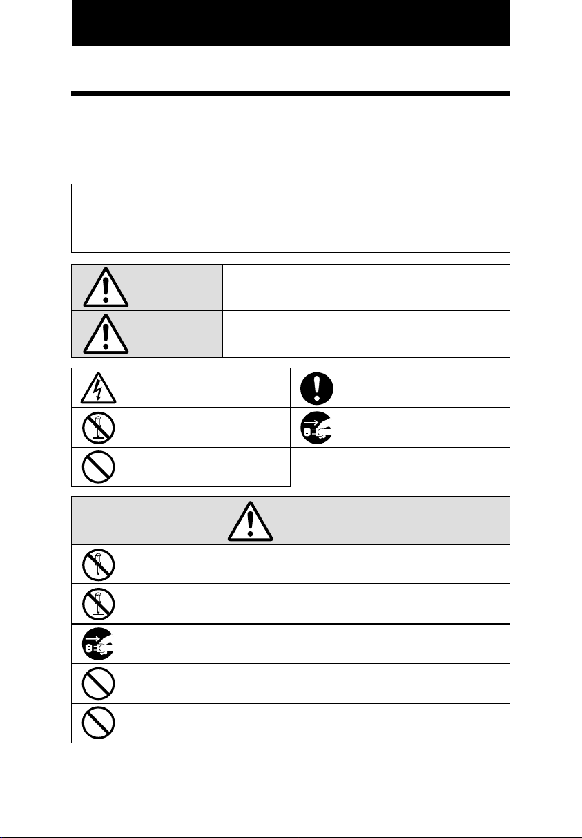
Signs
Various warnings and cautions are provided throughout this manual along with signs.
Remember each sign and its explanation listed below for your safety and proper
operation of the unit.
Caution
Warning
Improper handling may cause electric
shock DANGER.
DO NOT disassemble the unit.
"Don't" sign.
"Must-Do" sign.
Be sure to remove the line cord plug
from the outlet.
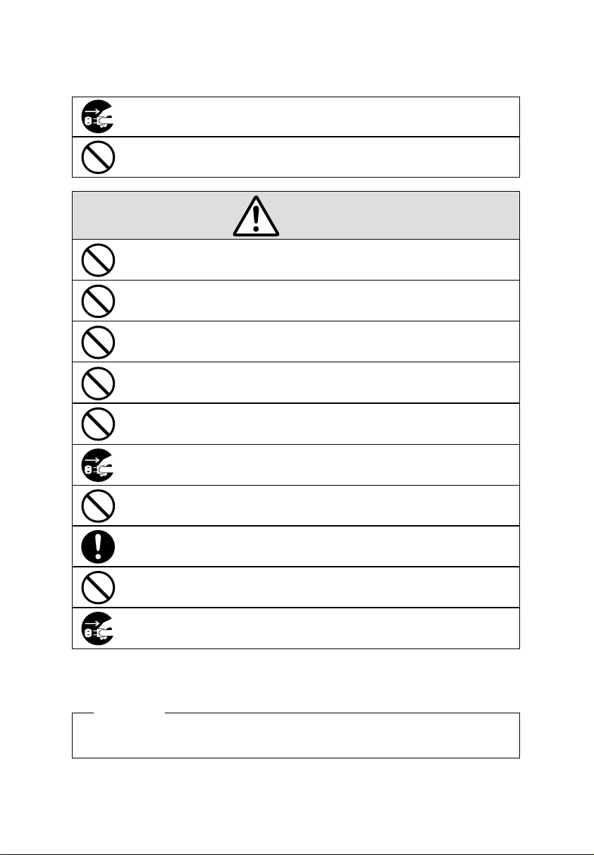
Do not disassemble the unit. There is a high voltage present inside, possibly leading to an
electric shock.
Do not use any voltage of the power source other than designated.
Do not share a single outlet with another plug. These may lead to fire or shock hazards.
Do not damage, break, or modify the power cord. Do not put a heavy object on, pull, or
forcefully bend the cord, either. These may damage the cord, possibly resulting in a fire or
electric shock.
If any anomaly occurs, for example, heat or smoke is generated or an odor is emitted, unplug
the unit immediately and contact your dealer for servicing. There is a danger that further use
may cause a fire or electric shock.
Do not modify the unit. Modifications may cause a fire and/or electric shock.
Warning
Improper handling may cause bodily accidents including
death and serious injury.
Improper handling may harm the human body or material.
1
1
Page 4
If foreign matter should get in the unit (including a piece of metal, water, or liquid), disconnect
the plug from the outlet immediately and contact your dealer for servicing. There is a danger
that further use may cause a fire or electric shock.
Do not plug or unplug the unit with a wet hand. You may get an electric shock.
Caution
Do not place the unit on an uneven or tilted surface. This may result in injuries due to the unit
dropping or falling off.
Do not put a water-filled container or a metal object on top of the unit. If water is spilled or the
metallic object slips inside, a fire or shock hazard may occur.
Do not install the unit in a humid or dusty environment. It may cause a fire or electric shock.
Do not place the unit near kitchen counter or humidifier. Oil, smoke, or steam generating from
them may cause fire or shock hazards.
Do not yank the power cord to disconnect from the outlet. Hold the plug with your hand to do
so, or the cord may be damaged, possibly leading to a fire or electric shock.
Remove the line cord plug from the outlet before transferring the unit, or it may damage the
cord, possibly leading to a fire or electric shock.
Be careful not to contact the print head, as you may get hurt or burned.
Make sure to insert the power plug as far as it will go. Improper insertion of the plug may
develop fire or shock hazards.
Do not insert or drop any other time card than specified into the slot. Such misuse may cause a
fire or electric shock.
If the unit should be dropped or the case be broken, unplug the unit and contact your dealer for
servicing. Further use may lead to a fire or shock hazard.
Daily C are
For cleaning, turn the power off and wipe the case clean of dust and dirt with a dry
cloth, etc.
2
2
Page 5

TABLE OF CONTENTS
INTRODUCTION & FEATURES
1.
BEFORE USING THE TIME RECORDER
2.
Attached Accessories
Location of Name
Print Position on Time Card
QUICK EASY SETUP
3.
OPTIONAL FUNCTIONS
4.
HOW TO PROGRAM THE TIME RECORDER
5.
SETTING THE TIME
6.
SETTING THE DATE
7.
SETTING THE 12/24 HOUR FORMAT
8.
SETTING THE PRINT ORDER
9.
SETTING THE PRINT PATTERN
10.
SETTING THE PREPROGRAMED COMMENTS
11.
SETTING THE CUSTOMIZED COMMENTS
12.
SETTING THE LANGUAGE
13.
SETTING THE PRINT METHOD
14.
SETTING THE DAYLIGHT SAVING TIME
15.
Deleting the Daylight Saving Time settings
SETTING THE NUMBER
16.
SETTING THE INITIAL NUMBER
17.
SETTING THE TIME TABLE PROGRAM
18.
SETTING THE EXTERNAL TIME SIGNAL / BUILT-IN BUZZER
19.
SETTING THE SLAVE CLOCK
20.
SETTING THE PASSWORD
21.
Registering the Password
How to change settings when the Password is set
Canceling the Password
RESETTING
22.
WALL MOUNTING
23.
REPLACING THE RIBBON CASSETTE
24.
CHARACTER CODE FOR ALPHANUMERIC
25.
INSTALLING THE Ni-Cd BATTERY (OPTIONAL)
26.
CONNECTING THE OPTIONAL FUNCTIONS
27.
Connecting the Master Clock
Connecting the External Time Signal
Attaching the Wire Clamp
TROUBLESHOOTING
28.
SPECIFICATIONS
29.
1
2
2
2
2
3
4
5
6
7
8
9
10
12
13
21
22
24
27
28
30
31
38
39
40
40
41
42
43
44
45
47
51
52
52
53
54
55
56
Page 6
1. INTRODUCTION & FEATURES
INTRODUCTON:
Thank you for purchasing the 5000E plus. We are confident this Time
Recorder will give you full satisfaction. Items such as the time and date
are preset at the factory. After plugging in the AC power the Time
Recorder can be used immediately. However, we recommend reading this
manual before you start using your Time Recorder.
FEATURES:
Main applications : Payroll/job cost recorder, time stamp or numbering
machine.
The Quartz Time Recorder
Dot-Matrix printer
Perpetual calendar
Automatic daylight saving time
4-way print activation
Automatic
Manual
Semi-automatic
Combination
Adjustable print position
Prints in 7 languages
Prints numbers/date
Time table program
Special mark printing
13 preprogrammed comments
For questions about the operation of this time clock, or to
order supplies and accessories, please contact Lathem Time
at (800)241-4990.
•
•
Alphanumeric printing
•
•
•
Selectable 4-digit year imprint
•
•
12 or 24-hour format
•
•
•
Regular minute, 1/10, 1/100
•
•
or 5/100 of an hour
•
•
Password for program protection
•
•
•
Digital LCD (Date, Hour,
•
•
Minute, Day of the week
•
•
•
indication)
•
•
Wall or desktop mount
•
•
Full power reserve (optional)
•
•
•
Slave clock functions (optional)
•
•
Built-in buzzer (optional)
•
•
•
External Time Signal (optional)
•
•
•
•
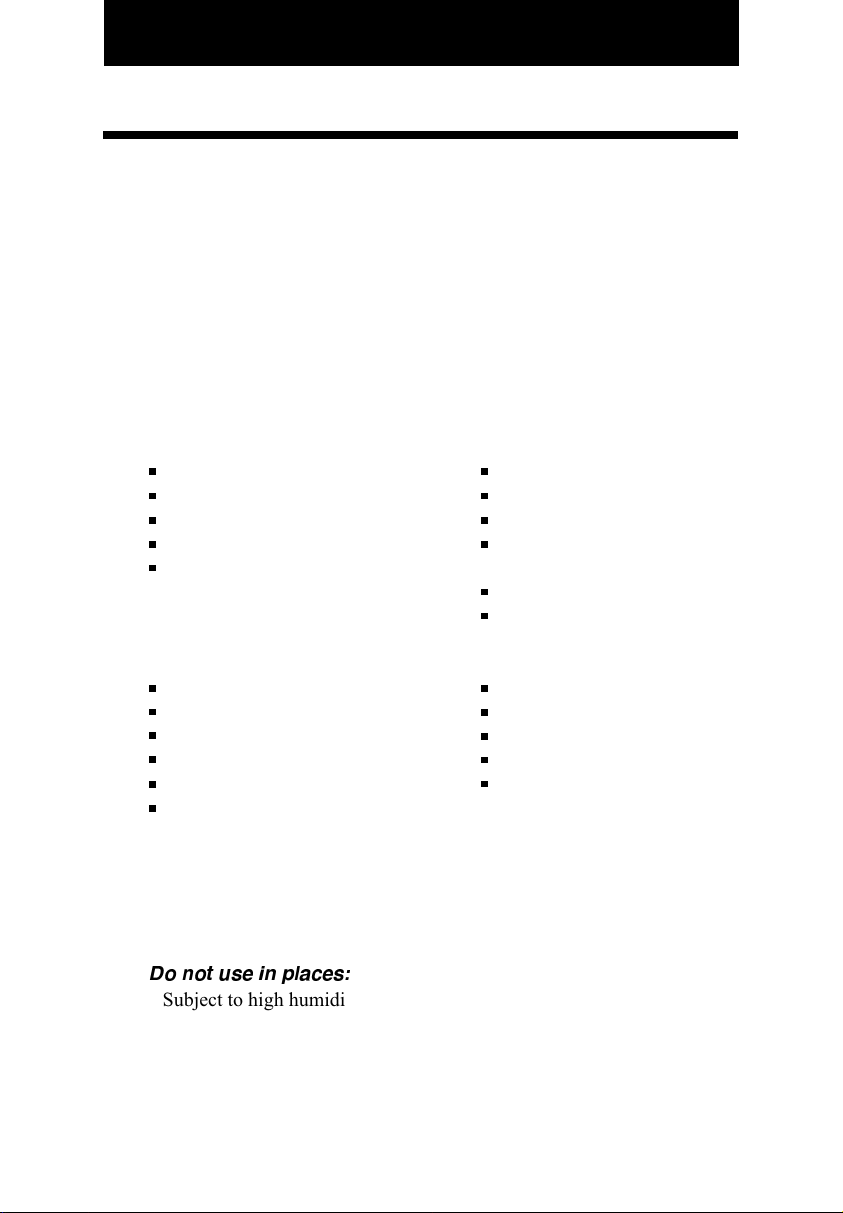
Caution:
1
Do not use in places:
Subject to high humidity and dust.
•
Exposed to strong or continuous vibrations.
•
Exposed to direct sunlight.
•
The temperature range in which all functions of the Time Recorder will
•
operate correctly is from -5˚C to 45˚C. Be sure therefore to place and
use your Time Recorder only in locations in which this temperature
range is not exceeded. Take care also not to subject your Time Recorder
to any sudden, sharp temperature variations.
2
Page 7
2.BEFORE USING THE TIME STAMP
Package Contents
Unpack the Time Recorder and check its contents to ensure that the Time
Recorder unit and all accessories as shown below are included.
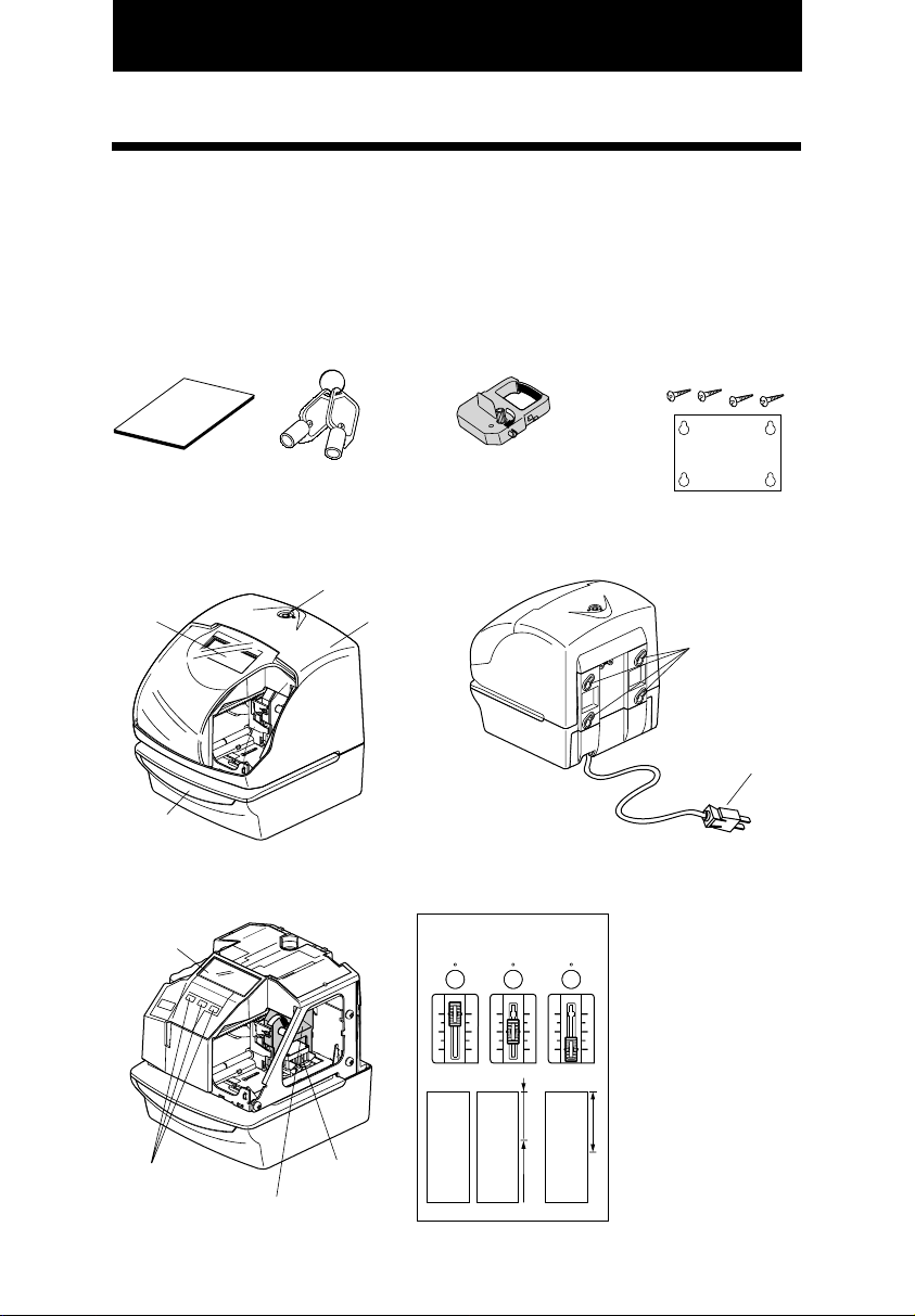
Attached Accessories
• User's Manual
• Keys
................2 pcs. ................1 pcs.
• Ribbon Cassette
• The ribbon casette is
installed at the factory.
• Wall-Mount Fittings
Screw
Template
.......4 pcs.
....1 sheet.
Location of Name
<Front view>
Display
Push bar
<Cover off>
Display
Control buttons
Ribbon cassette
Key hole
Print head
<Back view>
Cover
Wall-mount holes
AC power plug
(115VAC model)
Print Position on Time Card
<Print position adjuster>
JAN 31 12:00
JAN 31 12:00
15mm
Print position from the
card edge is adjustable
by pressing and sliding
the print position
button located on the
right outside bottom of
the Time Recorder.
Maximum distance
30mm
from edge of form to
print is approximately
1 3/16"(30mm).
JAN 31 12:00
2
1
2
Page 8
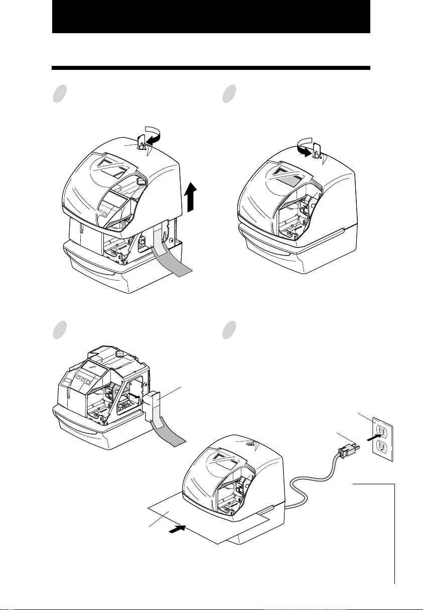
3. QUICK EASY SETUP
Unlock the key and remove the top
1
case.
Remove the PROTECTION PAD.
2
C
A
U
T
I
O
N
Protection PAD
Replace the cover and lock.
3
Plug the AC cord into the AC outlet
4
and insert a card.
AC outlet
Card
C
A
U
T
I
O
N
AC cord
JAN 31 12:00
(Print example)
2
3
2
Page 9

4. OPTIONAL FUNCTIONS
Following optional functions are available by adding an optional board.
External Time Signal for Bell, Built-in Buzzer and Slave Clock.
External Time Signal and Built-in Buzzer
External time signal and Built-in buzzer shall be controlled by Time table program and their
duration settings.
Refer to the "18.SETTING THE TIME TABLE PROGRAM", and the "19.SETTING THE
EXTERNAL TIME SIGNAL / BUILT-IN BUZZER".
Connection Specifications for External time signal contact
• Contact output: dry contact
• Contact capacity: 5A / 30V (Resistive)
The Slave Clock
The Slave Clock is a function to synchronize the time of Time Recorder and the master clock. This
function operates by choosing Slave Clock setup.
Refer to the "20.SETTING THE SLAVE CLOCK".
Input signal Specifications.
• 30-second reversal.
Since the 30-second signal (-V side) is not received, the difference from the master clock is 30
seconds or more, and the time is not modified correctly.
• 60-second reversal.
Since the odd-numbered signal (-V side) is not received, the difference from the master clock is
one minute or more, and the time is not modified correctly.
• 59-minute impulse ( 2-wire )
From the 59th minute through the 49th minute the pulse is transmitted with line AB positive with
respect to PC.
From the 50th minute to the 59th minute the pulse is transmitted with line AB negative with
respect to PC.
During the 59th minute, the continuous pulse of 20 times is transmitted with line AB negative
with respect to PC.
As this method monitors from 5 minutes before several preset hours to input 0-minute signal,
more than 5 minutes of tolerance for a master clock can not compensate time correctly.
Pulse Specification Input sensitivity
Pulse width 0.1 second or more
Voltage 6 - 32V
3
4
Page 10
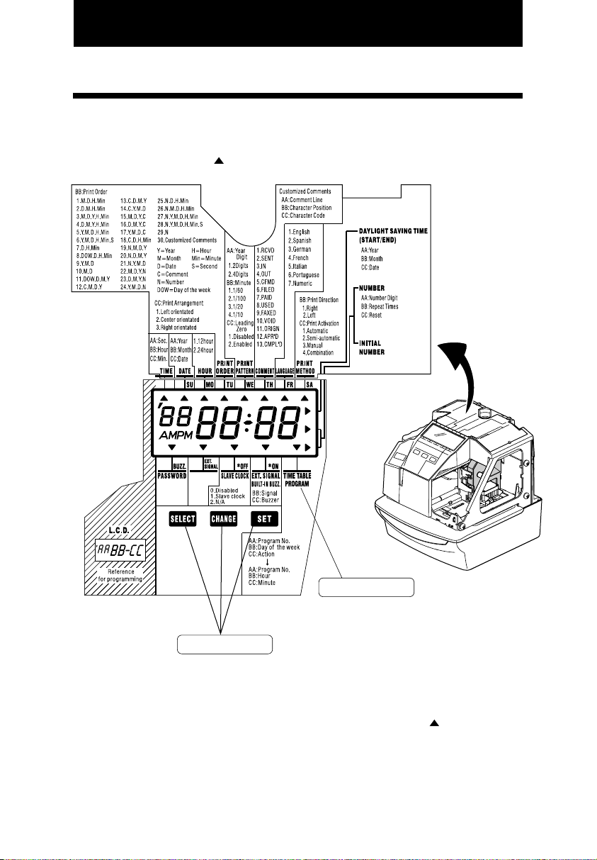
5. HOW TO PROGRAM THE TIME RECORDER
To enter the program setting mode, you must plug the AC cord into the AC outlet and
remove the cover. Next press the [SELECT] button once. Then the Time Recorder goes into
the program mode showing the " "on the display positioned under the "TIME" mark.
Program modes
Control buttons
Function of 3 control buttons
[SELECT]: You can select the desired program setting mode by pressing this [SELECT]
button. Selected program setting mode is indicated by the " " on the display.
[CHANGE]: When you press the [CHANGE] button, you can increment the set value.
[SET]: You can set the value selected on the display by pressing the [SET] button.
Thereafter you press this [SET] button again, you can return the Time
Recorder to the normal operation mode.
5
2
2
Page 11
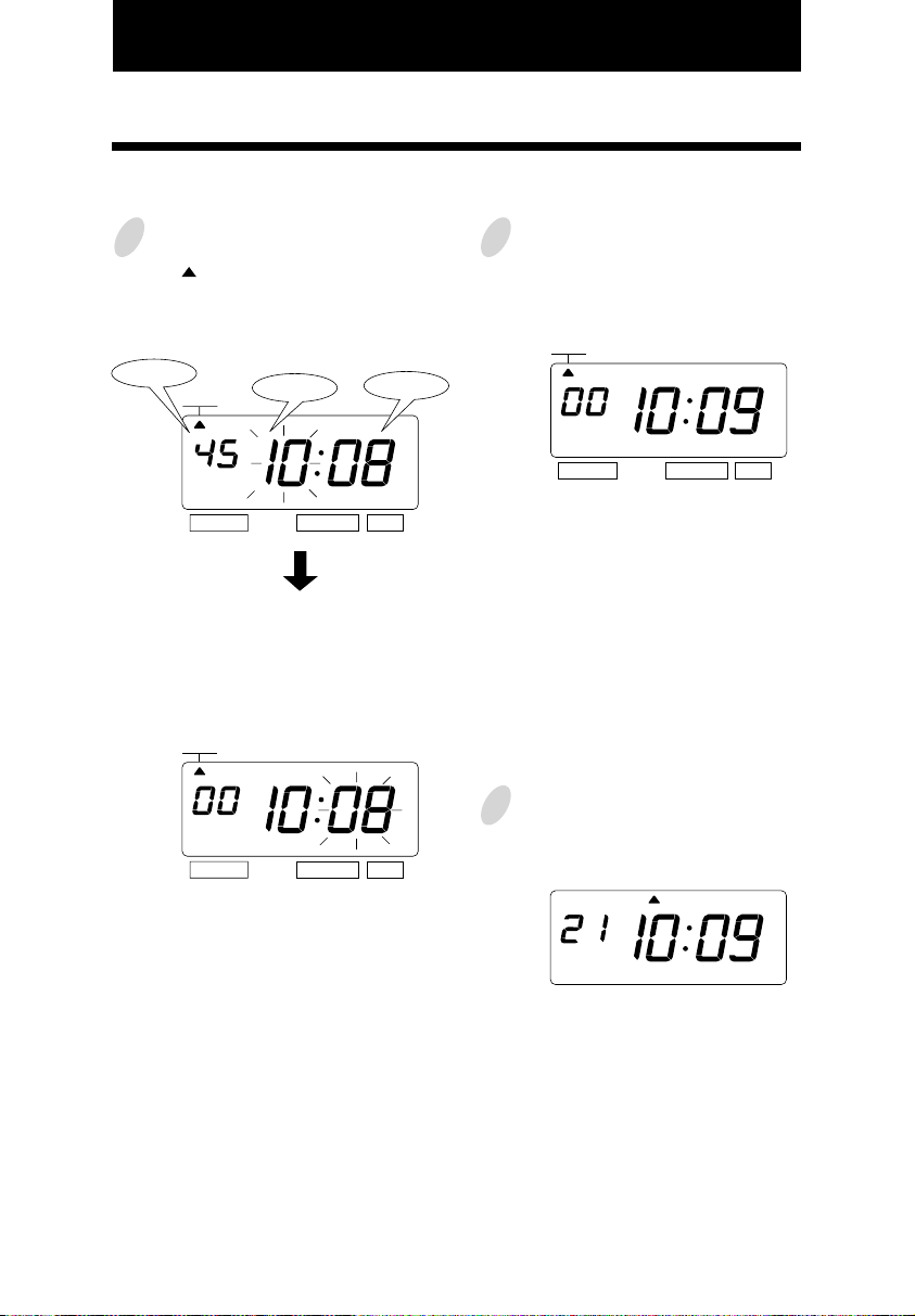
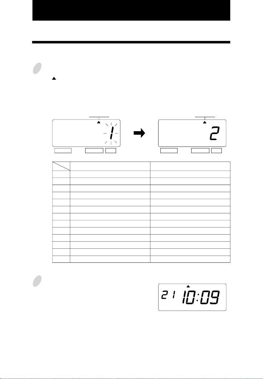
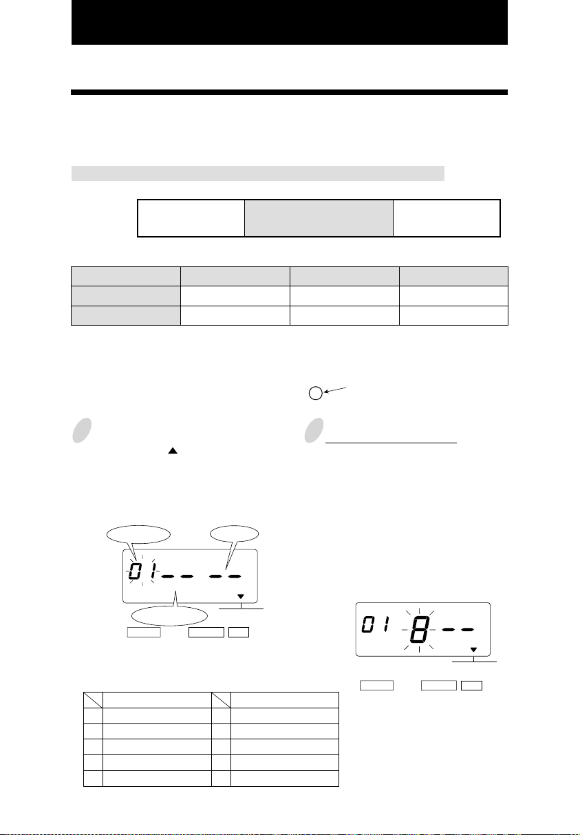
6. SETTING THE TIME
Example: Change the time from 10:08 to 10:09.
Press the [SELECT] button and position
1
the " " under the "TIME" mark.
At that moment, the "Hour" flashes.
(The flashing means it can be changed.)
Seconed
TIME
SELECT CHANGE SET
Change the "Hour".
In case of the example, press the
[SET] button because the hour is not
to be changed.
TIME
SELECT CHANGE SET
At that moment, the flashing changes
from "Hour" to "Minute".
Hour
Minute
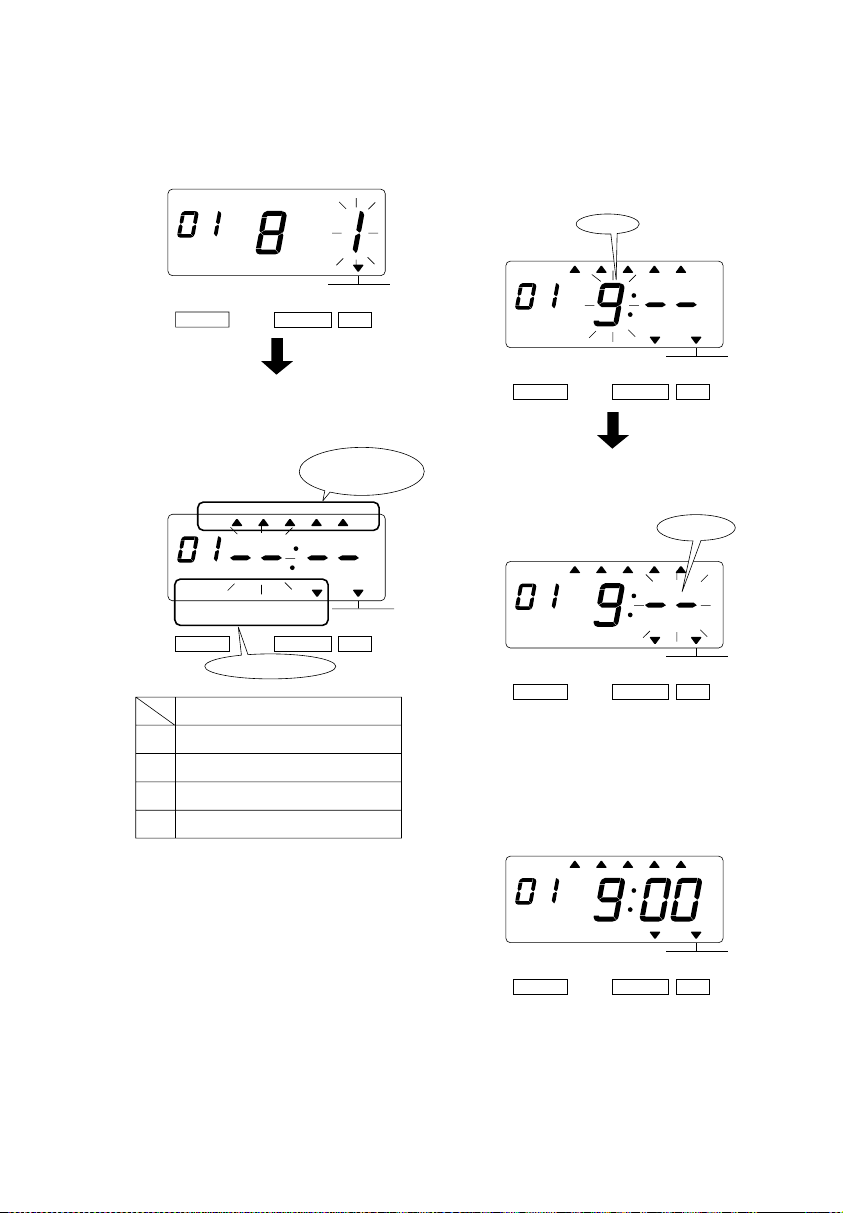
Change the "Minute".
2
Press the [CHANGE] button to set at
"09". And then press the [SET] button.
TIME
SELECT CHANGE SET
At that moment, the "Second" starts to
run from "00".
After you finish setting the time, press
3
the [SET] button once again.
MO TU WE TH FR SASU
Now the time setting has been
completed. Replace the cover and
lock.
Important: If you do not complete Step
3, the Time Recorder will not print.
3
6
Page 12
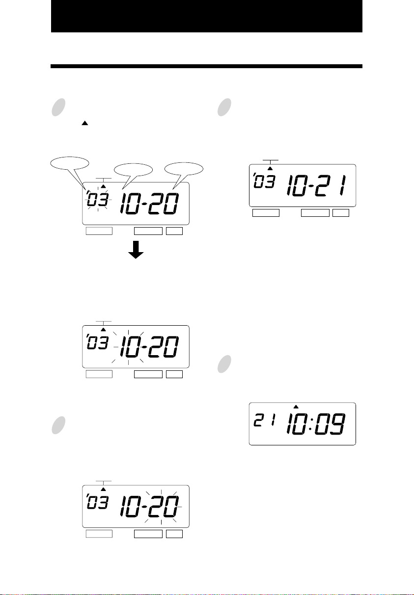
7. SETTING THE DATE
Example: Change the date from October 20, 2003 to October 21, 2003.
1
Press the [SELECT] button and position
the " " under the "DATE" mark.
At that moment, the "Year" flashes. (The
flashing means it can be changed.)
Year
SELECT CHANGE SET
Change the "Year".
In case of the example, press the
[SET] button because the year 2003 is
not to be changed.
SELECT CHANGE
At that moment, the flashing changes
from "Year" to "Month".
DATE
DATE
Month
SET
Date
Change the "Date".
3
Press the [CHANGE] button to set at
"21". And then press the [SET] button.
DATE
SELECT CHANGE SET
After you finish setting the date, press
4
the [SET] button once again.
MO TU WE TH FR SASU
Change the "Month".
2
In case of the example, press the
[SET] button because the month is not
to be changed.
DATE
SELECT CHANGE
At that moment, the flashing changes
7
from "Month" to "Date".
SET
Now the date setting has been
completed. Replace the cover and
lock.
Important: If you do not complete Step
4, the Time Recorder will not print.
6
Page 13
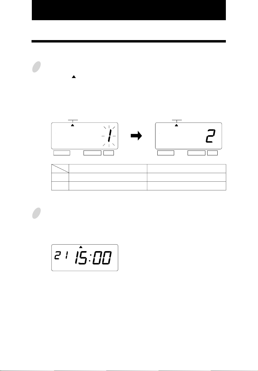
8. SETTING THE 12/24 HOUR FORMAT
Example: Change the hour format to 24 hour.
Press the [SELECT] button and
1
position the " " under the "HOUR"
mark.
At that moment, the flashing digit
indicates "Hour Format Options".
(The flashing means it can be changed.)
HOUR
SELECT CHANGE SET
Hour Format Options
1.
2.
After you finish setting the 12/24 hour
2
format, press the [SET] button once
again.
12 hour
24 hour
MO TU WE TH FR SASU
Change the "Hour".
In case of the example, press the
[CHANGE] button to set at "2". And
then press the [SET] button.
HOUR
SELECT CHANGE SET
Display
PM 3:00
15:00
Now the 12/24 hour setting has been
completed. Replace the cover and
lock.
Important: If you do not complete Step
2, the Time Recorder will not print.
3
8
Page 14
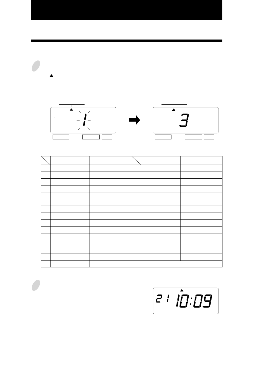
9. SETTING THE PRINT ORDER
Example: Set the print order to "Month, Date, Year, Hour, Minute".
Press the [SELECT] button and position
1
the " " under the "PRINT ORDER" mark.
At that moment, the flashing digit
indicates "Print Order Options".
Change the "Print Order Options".
In case of the example, press the
[CHANGE] button to set at "3". And
then press the [SET] button.
(The flashing means it can be changed.)
PRINT ORDER
SELECT CHANGE SET
PRINT ORDER
SELECT CHANGE SET
Y=Year, M=Month, D=Date, DOW=Day of the week, H=Hour, Min=Minute, S=Second
C=Comment, N=Number
Print Order Options
M.D.H.Min
1.
D.M.H.Min
2.
M.D.Y.H.Min
3.
D.M.Y.H.Min
4.
Y.M.D.H.Min
5.
Y.M.D.H.Min.S
6.
D.H.Min
7.
DOW.D.H.Min
8.
Y.M.D
9.
M.D
10.
DOW.D.M.Y
11.
C.M.D.Y
12.
C.D.M.Y
13.
C.Y.M.D
14.
M.D.Y.C
15.
Print Example
JAN 31 10:00
31 JAN 10:00
JAN 31 '03 10:00
31 JAN '03 10:00
'03 JAN 31 10:00
'03 JAN 31 10:00:00
31 10:00
FR, 31 10:00
'03 JAN 31
JAN 31
FR, 31 JAN '03
SENT JAN 31 '03
SENT 31 JAN '03
SENT '03 JAN 31
JAN 31 '03 SENT
Print Order Options
16.
D.M.Y.C
17.
Y.M.D.C
18.
C.D.H.Min
19.
N.M.D.Y
20.
N.D.M.Y
21.
N.Y.M.D
22.
M.D.Y.N
23.
D.M.Y.N
24.
Y.M.D.N
N.D.H.Min
25.
N.M.D.H.Min
26.
N.Y.M.D.H.Min
27.
N.Y.M.D.H.Min.S
28.
N
29.
Customized Comments
30.
Print Example
31 JAN '03 SENT
'03 JAN 31 SENT
SENT 31 10:00
000123 JAN 31 '03
000123 31 JAN '03
000123 '03 JAN 31
JAN 31 '03 000123
31 JAN '03 000123
'03 JAN 31 000123
000123 31 10:00
123 JAN 31 10:00
123 '03 JAN 31 10:00
123 '03 JAN 31 10:00:00
000123
2
After you finish setting the print order,
MO TU WE TH FR SASU
press the [SET] button once again.
Now the print order setting has been
completed. Replace the cover and
lock.
Important: If you do not complete Step
2, the Time Recorder will not print.
9
9
Page 15
10. SETTING THE PRINT PATTERN
In this setup, the printing of Year digit, the printing type of Minutes, and change of Leading
Zero can be set.
Example: Change the Year imprint to 4 digits and the Minutes to 1/100 min. and the Leading
Zero to enabled.
Press the [SELECT] button and position
1
the " " under the "PRINT PATTERN"
mark.
At that moment, the flashing digit
indicates "Year Digit Options".
(The flashing means it can be changed.)
Year
Digit
Change the "Type of Minute".
2
In case of the example, press the
[CHANGE] button to set at "2". And
then press the [SET] button.
At that moment, the flashing changes
from "Type of Minute" to "Leading
Zero".
Type of
Minute
SELECT CHANGE SET
1.
2.
PRINT
PATTERN
Year Digit Options
2 Digits
4 Digits
Leading
Zero
Change the "Year Digit".
In case of the example, press the
[CHANGE] button to set at "2". And
then press the [SET] button.
At that moment, the flashing changes
from the "Year Digit Options" to
"Type of Minute".
PRINT
PATTERN
SELECT CHANGE SET
Print Example
JAN 31 '03 10:00
JAN 31 2003 10:00
PRINT
PATTERN
SELECT CHANGE SET
Type of Minute
1.
2.
3.
4.
1/60 Min.
1/100 Min.
1/20 Min. (= 5/100 Min.)
1/10 Min.
3
Print Example
JAN 31 2003 10:10
JAN 31 2003 10.17
JAN 31 2003 10.15
JAN 31 2003 10.1
10
Page 16
Change the "Leading Zero".
3
In case of the example, press the
[CHANGE] button to set at "2". And
then press the [SET] button.
PRINT
PATTERN
SELECT CHANGE SET
Leading Zero
1.
2.
After you finish setting the print
4
pattern, press the [SET] button once
again.
Now the print pattern setting has been
completed. Replace the cover and
lock.
Important: If you do not complete Step
4, the Time Recorder will not print.
ZERO Disabled
ZERO Enabled
Print Example
JAN 1 3:00
JAN 01 03:00
MO TU WE TH FR SASU
11
10
Page 17
11. SETTING THE PREPROGRAMED COMMENTS
Example: Change the comment to "SENT".
Press the [SELECT] button and position
1
the " " under the "COMMENT" mark.
At that moment, the flashing digit
indicates "Comment Options".
(The flashing means it can be changed.)
COMMENT
SELECT CHANGE SET
Comment Options
RCVD (Received)
1.
SENT
2.
IN
3.
OUT
4.
CFMD (Confirmed)
5.
FILED
6.
PAID
7.
USED
8.
FAXED
9.
10.
11.
12.
13.
VOID
ORIGN (Original)
APR'D (Approved)
CMPL'D (Completed)
Change the "Comment Options".
In case of the example, press the
[CHANGE] button to set at "2".
And then press the [SET] button.
COMMENT
SELECT CHANGE SET
Print Example
JAN 31 '03 RCVD
JAN 31 '03 SENT
JAN 31 '03 IN
JAN 31 '03 OUT
JAN 31 '03 CFMD
JAN 31 '03 FILED
JAN 31 '03 PAID
JAN 31 '03 USED
JAN 31 '03 FAXED
JAN 31 '03 VOID
JAN 31 '03 ORIGN
JAN 31 '03 APR'D
JAN 31 '03 CMPL'D
11
2
After you finish setting the comment,
press the [SET] button once again.
Now the preprogrammed comments
setting has been completed. Replace
the cover and lock.
Important: If you do not complete Step
2, the Time Recorder will not print.
MO TU WE TH FR SASU
12
Page 18
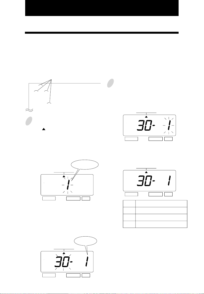
12. SETTING THE CUSTOMIZED COMMENTS
• Maximum 3 lines comment can be set to print.
• Note: This Time Recorder can print 31 characters (161 font size) at maximum, however
number of characters depends on font size. Refer to the "25.CHARACTER CODE
FOR ALPHANUMERIC".
Example:
space
2
ABC HOTEL ......... 1st comment line
21 OCT '03 ........... 2nd comment line
(Date, Month, Year)
BOSTON, MA ....... 3rd comment line
1
Press the [SELECT] button and position
the " " under the "PRINT ORDER"
mark.
At that moment, the flashing digit
indicates "Print Order Options".
(The flashing means it can be changed.)
Print
PRINT ORDER
Order Options
And then press the [SET] button. At
that moment, the flashing digit
changes from "Print Order Options" to
"Print Position".
PRINT ORDER
SELECT CHANGE SET
In case of example, press the [SET]
button because the print position is not
to be changed.
PRINT ORDER
13
SELECT CHANGE SET
Press the [CHANGE] button to set at
the "30" (Customized Comments). At
that moment, a digit for "Print
Position" appears next to "Print Order
Options".
Print
PRINT ORDER
SELECT CHANGE SET
Position
SELECT CHANGE SET
Print Position
Left Orientated
1.
Center Orientated
2.
3.
Right Orientated
13
Page 19
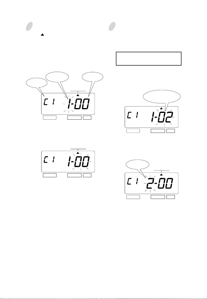
3
Press the [SELECT] button and position
the " " under the "COMMENT" mark.
Setting the 1st comment line.
At the moment, the flashing digit
indicates "Character Position". And then
press the [SET] button.
Character
Comment
Line
Position
COMMENT
SELECT CHANGE SET
Character
Code
4
Set the "Character Code".
In case of example, the 1st character is
"A", then enter the character code
"02".
Refer to the "25. CHARACTER
CODE FOR ALPHANUMERIC"
Press the [CHANGE] button until the
correct character code appears. And
then press the [SET] button.
The character code
"02" means "A".
At the moment, the flashing changes
from "Character Position" to "Character
Code".
COMMENT
SELECT CHANGE SET
SELECT CHANGE SET
At that moment, the "Character
Position" changes from the 1st
character to the 2nd character.
The 2nd
Character
SELECT CHANGE SET
COMMENT
14
14
Page 20

5
The 2nd character is "B", then enter
the character code "03".
COMMENT
SELECT CHANGE SET
Press the [CHANGE] button until the
correct character code appears. And
then press the [SET] button.
The character code
"03" means "B".
7
Follow the same procedure for further
characters settings.
8
Setting the 2nd comment line
Press the [SET] button to change the
comment line number to "C2".
The 2nd
comment line
SELECT CHANGE SET
In case of example, the 1st character is
"DATE", then enter the character code
"28".
COMMENT
SELECT CHANGE SET
6
The 3rd character is "C", then enter
the character code "04".
The 3rd
character
SELECT CHANGE SET
Press the [CHANGE] button until the
correct character code appears. And
then press the [SET] button.
SELECT CHANGE SET
COMMENT
The character code
"04" means "C".
Press the [CHANGE] button until the
correct character code appears. And
then press the [SET] button.
The character code
"28" means "DATE".
SELECT CHANGE SET
15
14
Page 21

16
15
9
The 2nd character is "SPACE", then
enter the character code "01".
Press the [CHANGE] button until the
correct character code appears. And
then press the [SET] button.
SELECT CHANGE SET
Follow the same procedure for further
characters settings.
12
11
10
Setting the 3rd comment line
Press the [SET] button to change the
comment line number to "C3".
SELECT CHANGE SET
The character code
"01" is "SPACE".
The 3rd character is "MONTH", then
enter the character code "27".
Press the [CHANGE] button until the
correct character code appears. And
then press the [SET] button.
SELECT CHANGE SET
SELECT CHANGE SET
The 3rd
character
In case of example, the 1st character is
"B", then enter the character code
"03".
Press the [CHANGE] button until the
correct character code appears. And
then press the [SET] button.
SELECT CHANGE SET
SELECT CHANGE SET
The character code
"03" means "B".
The character code"27"
means "MONTH".
COMMENT
COMMENT
COMMENT
The 3rd
comment line
Page 22

16
17
13
The 2nd character is "O", then enter
the character code "10".
Press the [CHANGE] button until the
correct character code appears. And
then press the [SET] button.
SELECT CHANGE SET
15
After you finish setting the
customized comments, press the
[SET] button three times.
Now the customized comments setting
has been completed. Replace the cover
and lock.
Important: If you do not completed
Step 15, the Time Recorder will not
print.
SELECT CHANGE SET
The character code
"10" means "O".
14
Set the last character "A" in the same
manner as above.
SELECT CHANGE SET
The 10th
character
The 2nd
character
Use below code number correction.
The character code
"02" means "A".
MO TU WE TH FR SASU
HOW TO CORRECT
CUSTOMIZED COMMENTS
Code
F8
F9
FA
Fb
FC
Fd
FE
FF
Meaning
Insert Character
Delete Character
Insert Line
Delete Line
Exchange Line 1 to 2
Exchange Line 2 to 3
Exchange Line 1 to 3
Delete All
COMMENT
Page 23

Setting the Print Position of Customized Comments
Left orientated
ABC HOTEL
21 OCT '03
BOSTON, MA
Example: Change the print position to "Center orientated".
1
Press the [SELECT] button and position
the " " under the "PRINT ORDER"
mark.
At that moment, the flashing digit
indicates "Print Order Options".
(The flashing means it can be changed.)
PRINT ORDER
SELECT CHANGE SET
In case of the example, press the
[SET] button because the "Print Order
Options" not to be changed. At that
moment, the flashing digit indicates
"Print position".
Center orientated
ABC HOTEL
21 OCT '03
BOSTON, MA
Print Order
Options
2
Change the "Print Position".
In case of example, press the
[CHANGE] button to set at "2". And
then press the [SET] button.
3
After you finish setting the print order
and the print position, press the [SET]
button once again.
Right orientated
ABC HOTEL
21 OCT '03
BOSTON, MA
PRINT ORDER
SELECT CHANGE SET
MO TU WE TH FR SASU
18
Print
PRINT ORDER
SELECT CHANGE SET
Print Position
Left Orientated
1.
Center Orientated
2.
3.
Right Orientated
Position
Now the print order and the print
position settings have been completed.
Replace the cover and lock.
Important: If you do not complete Step
3, the Time Recorder will not print.
18
Page 24

Confirming and Changing the Customized Comments
Example: 1st comment line: No change.
2nd comment line: Change from "Year" to time "HH:MM".
3rd comment line: No change.
ABC HOTEL
Year
21 OCT '03
BOSTON, MA
Confirming the 1st comment line
1
To confirm the customized comments that
have been set, press the [SELECT] button
and position the " " under the
"COMMENT" mark. At that moment, the
"Character Position" flashes, and press the
[CHANGE] button.
While the "Character Position" changes,
the "Character Code" that has been set
appears.
Comment
Line
Character
Position
COMMENT
SELECT CHANGE SET
COMMENT
Character
Code
ABC HOTEL
Time
21 OCT 10:03
BOSTON, MA
At that moment, the display changes
to the following figure.
"00" means
"NULL".
COMMENT
SELECT CHANGE SET
At this time, press the [SET] button
twice, and the 2nd comment line is
displayed.
The 2nd
comment line
COMMENT
19
SELECT CHANGE SET
The last
character code
SELECT CHANGE SET
After confirming the last character
code of the 1st comment line, press
the [CHANGE] button once again.
SELECT CHANGE SET
18
Page 25

2
Changing
the Customized Comments
In case of example, press the
[CHANGE] button to set at "5". And
then press the [SET] button. At that
moment, flashing changes from the
"Character Position" to the
"Character Code".
The character code
"26" means "Year".
COMMENT
SELECT CHANGE SET
Press the [CHANGE] button to set at
"2A".
The character code
"2A" means HH:MM"
COMMENT
SELECT CHANGE SET
Then press the [SET] button once.
Now changing the character code has
been completed.
3
Confirming the 3rd comment line
Confirm the 3rd comment line in the
same manner as Step 1.
Character
Position
Cord
Meaning
Character
Meaning
Date01SPACE27Month01SPACE26Year
Position
Cord
Date01SPACE27Month01SPACE2AHH:MM
4
After you finish confirming and
2 3 4 5
1
28
1
2 3 4 5
28
changing the customized comments,
press the [SET] button once again.
MO TU WE TH FR SASU
19
Now confirming and changing the
customized comments have been
completed. Replace the cover and
lock.
Important: If you do not complete Step
4, the Time Recorder will not print.
20
Page 26

13. SETTING THE LANGUAGE
This setting is available if you select "Month", "Day of the week" or "Comment" in
previous "PRINT ORDER".
Example: Change the print language into Spanish.
Press the [SELECT] button and position
1
the " " under the "LANGUAGE" mark.
At that moment, the flashing digit
indicates "Print Language Options".
(The flashing means it can be changed.)
LANGUAGE
SELECT CHANGE SET
Print Language Options
ENGLISH
1.
SPANISH
2.
GERMAN
3.
FRENCH
4.
ITALIAN
5.
PORTUGUESE
6.
NUMERIC
7.
Change the "Language".
In case of the example, press the
[CHANGE] button to set at "2".
And then press the [SET] button.
LANGUAGE
SELECT CHANGE SET
Print Example
TH, 25 DEC '03
OUT 31 10:00
JU, 25 DIC '03
SAL 31 10:00
DO, 25 DEZ '03
AUSG 31 10:00
JE, 25 DEC '03
SORT 31 10:00
GI, 25 DIC '03
USC 31 10:00
QI, 25 DEZ '03
SAIDA 31 10:00
4, 25-12 '03
OUT 31 10:00
21
After you finish setting the language,
2
press the [SET] button once again.
Now the language setting has been
completed. Replace the cover and
lock.
Important: If you do not complete Step
2, the Time Recorder will not print.
MO TU WE TH FR SASU
20
Page 27

14. SETTING THE PRINT METHOD
Example: Change the print direction to "Left" and the print activation to "Manual".
Press the [SELECT] button and position
1
the " " under the "PRINT METHOD"
mark.
At that moment, the flashing digit
indicates "Print Direction Options".
(The flashing means it can be changed.)
Print
direction
SELECT CHANGE SET
1.
2.
Change the "Print Activation".
2
In case of the example, press the
[CHANGE] button to set at "3".
And then press the [SET] button.
Print
method
METHOD
Print Direction Options
Right
Left
METHOD
PRINT
PRINT
Change the "Print Direction".
In case of the example, press the
[CHANGE] button to set at "2".
And then press the [SET] button.
At that moment, the flashing changes
from the "Print Direction" to the "Print
Activation".
PRINT
METHOD
SELECT CHANGE SET
21
SELECT CHANGE SET
Print Activation Options
1.
2.
3.
4.
Automatic
Semi-automatic
Manual
Combination
22
Page 28

After you finish setting the print
3
method, press the [SET] button once
again.
MO TU WE TH FR SASU
Now the print method setting has been
completed. Replace the cover and
lock.
Important: If you do not complete Step
3, the Time Recorder will not print.
Automatic will allow the Time
Recorder to print by simply inserting a
card or piece of paper.
Semi-automatic will allow the Time
Recorder to print by pressing the push
bar only when a card or piece of paper
is inserted.
23
Manual will allow the Time Recorder
to print by pressing the push bar.
Combination will allow the Time
Recorder to print by pressing the push
bar or inserting a card or piece of
paper.
Push bar
22
Page 29

15. SETTING THE DAYLIGHT SAVING TIME
Daylight Saving Time function
D.S.T. execution time
1
At 2:00 a.m. on the first day of DST, the clock automatically gains
one hour to show 3:00 a.m.
When 3:00 a.m. comes on the last day of the DST, it loses one hour
and returns to 2:00 a.m.
Setting D.S.T.
2
Example:
Start date Sunday, April 6, 2003
End date Sunday, October 26, 2003
If set as the above, the unit remembers the start date as the first
Sunday of April and the end date as the last Sunday of October.
Once set, the unit automatically updates the settings every year
thereafter. No further manual setting is necessary.
The setting for daylight saving time will be
Example
described using the following example.
Today (present day)
Starting date of daylight
saving time
Ending date of daylight
saving time
1
Press the [SELECT] button and position the " " next to the "DAYLIGHT SAVING
TIME" mark. (The flashing means it can be changed.)
Year
23
Wednesday, January 29, 2003
Sunday, April 6, 2003
Sunday, October 26, 2003
Month
SELECT CHANGE SET
Date
" " mark means
"starting date" setting
The first Sunday of April
The last Sunday of October
DAYLIGHT SAVING TIME
24
Page 30

Set the starting date.
Change the "Year".
2
In case of the example, press the
[SET] button because the year 2003 is
not to be changed.
SELECT CHANGE SET
At the moment, the flashing changes
from "Year" to "Month".
SELECT CHANGE SET
Change the "Month".
3
Push the [CHANGE] button to set at
"4" and push the [SET] button.
SELECT CHANGE SET
At the moment, the flashing changes
from "Month" to "Date".
Change the "Date".
4
Push the [CHANGE] button to set at
"6" and push the [SET] button.
SU
At the moment, the "startingt date" of
the display changes from flashing to
steady and the " " mark is displayed
under "SU".
SU
MO TU WE TH FR SASU
After a few second, go on to the "set
the ending date".
Please see the following page.
25
SELECT CHANGE SET
24
Page 31

Set the ending date.
Change the "Year".
5
In case of the example, press the
[SET] button because the year 2003 is
not to be changed.
Year
SELECT CHANGE SET
At the moment, the flashing changes
from "Year" to "Month".
Month
Date
DAYLIGHT SAVING TIME
" " mark means
"ending date" setting
Change the "Date".
7
Push the [CHANGE] button to set at
"26" and push the [SET] button.
SU
25
SELECT CHANGE SET
Change the "Month".
6
Push the [CHANGE] button to set at
"10" and push the [SET] button.
SELECT CHANGE SET
At the moment, the flashing changes
from "Month" to "Date".
SELECT CHANGE SET
At the moment, the "ending date" of
the display changes from flashing to
steady and the " " mark is displayed
under "SU".
SU
After you finish setting the daylight
8
saving time, press the [SET] button
once again.
MO TU WE TH FR SASU
Now the daylight saving time setting
has been completed. Replace the cover
and lock.
Important: If you do not complete Step
8, the Time Recorder will not print.
26
Page 32

Deleting the Daylight Saving Time settings
To delete and cancel the daylight saving time settings, change the display of "Month" of the
starting setting to " ".
Example: To change April 6, 2003 of "starting date" and delete daylight saving time settings.
Press the [SELECT] button and position
1
the " " next to the "DAYLIGHT
SAVING TIME" mark.
(The flashing means it can be changed.)
Year
SELECT CHANGE SET
Press the [SET] button and the flashing
2
changes from "Year" to "Month".
Month
SU
SU
DAYLIGHT
SAVING TIME
Press the [CHANGE] button to set at
3
" ".
SU
Press the [SET] button twice. This
cancels the daylight saving time
settings.
After you finish deleting the daylight
4
saving time, press the [SET] button
once again.
MO TU WE TH FR SASU
27
SELECT CHANGE SET
Now the deleting the daylight saving
time has been completed. Replace the
cover and lock.
Important: If you do not complete Step
4, the Time Recorder will not print.
26
Page 33

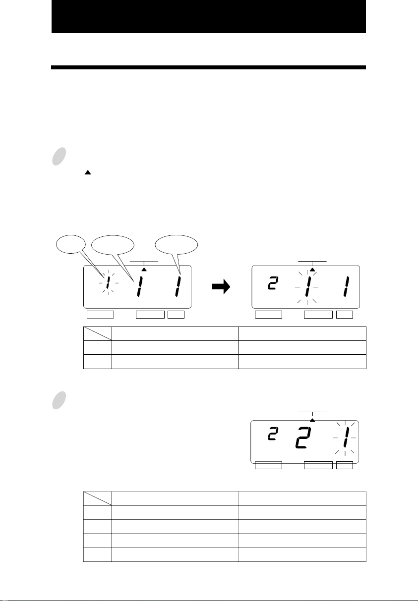
16. SETTING THE NUMBER
In this setup, you can select digits of printed number, the Repeat Times of number, and type
of Number Reset .
Example: Change the Number Digit to 4 digits and the Repeat Times to 2 times, and the
Reset to 0.
1
Press the [SELECT] button and position
the " "next to the "NUMBER" mark.
At that moment, the flashing digit
indicates "Number Digit".
(The flashing means it can be changed.)
Number
Digit
Print Example: 6 Digits of Number 123456 JAN 31 '03
4 Digits of Number 1234 JAN 31 '03
Change the "Repeat Times".
2
The Repeat Times can be set to 0 to 9.
In case of the example, press the
[CHANGE] button to set at "2". And
then press the [SET] button.
At that moment, the flashing changes
from "Repeat Times" to "Reset
Options".
Print Example: 0 time repeat
Repeat
Times
SELECT CHANGE SET
Reset
Options
NUMBER NUMBER
(1st time)
(2nd time)
(3rd time)
(4th time)
(5th time)
Change the "Number Digit".
The Number Digit can be set to 1 to 8.
In case of the example, press the
[CHANGE] button to set at "4". And
then press the [SET] button.
At that moment, the flashing changes
from the "Number Digit" to "Repeat
Times".
123456 JAN 31 '03
123456 JAN 31 '03
123456 JAN 31 '03
123456 JAN 31 '03
123456 JAN 31 '03
SELECT CHANGE SET
NUMBER
SELECT CHANGE SET
27
2 times repeat
(1st time)
(2nd time)
(3rd time)
(4th time)
(5th time)
123456 JAN 31 '03
123456 JAN 31 '03
123457 JAN 31 '03
123457 JAN 31 '03
123458 JAN 31 '03
28
Page 34

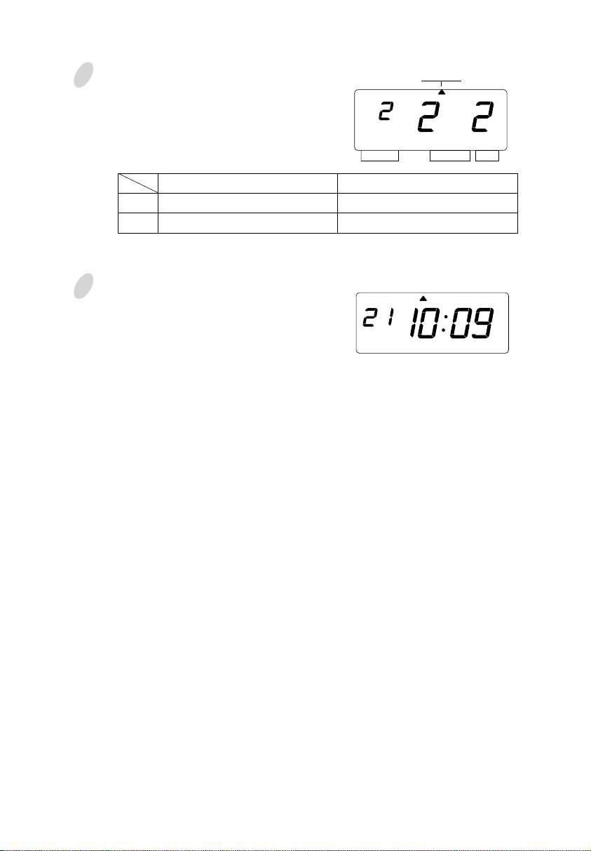
Change the "Reset Options".
3
In case of the example, press the
[CHANGE] button to set at "3". And
then press the [SET] button.
NUMBER
SELECT CHANGE SET
Reset Options
1.
2.
3.
After you finish setting the number,
4
press the [SET] button once again.
Now the number setting has been
completed. Replace the cover and
lock.
Important: If you do not complete Step
4, the Time Recorder will not print.
Disabled
Return to INITIAL NUMBER
Return to 0
Execution event of Reset.
Change of date
Change of date
MO TU WE TH FR SASU
29
28
Page 35
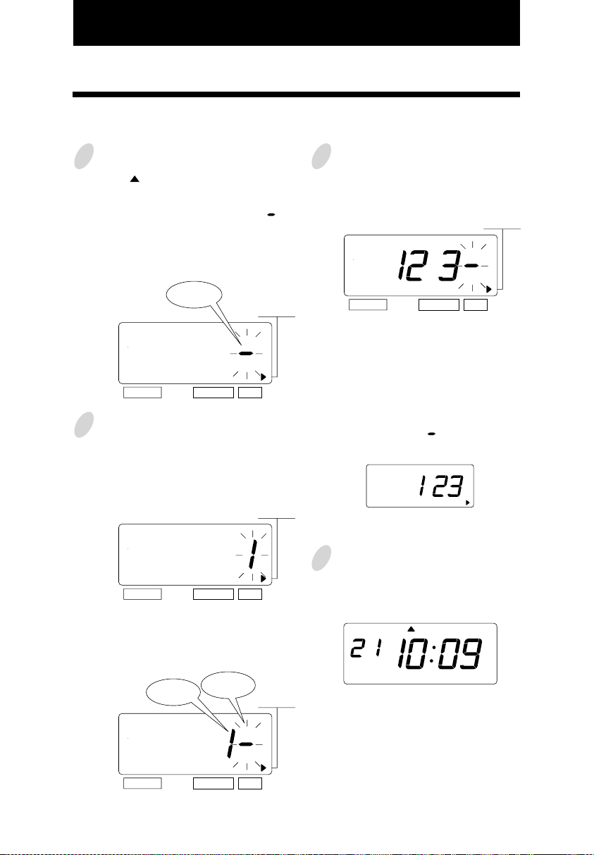
17. SETTING THE INITIAL NUMBER
Example: Setting the initial number to "123". Refer to "16. SETTING THE NUMBER".
1
Press the [SELECT] button and position
the " " next to the "INITIAL
NUMBER" mark.
At that moment, the flashing " "
indicates the 1st digit of the initial
number.
(The flashing means it can be changed.)
The1st
digit
SELECT CHANGE SET
2
Set the "Initial Number".
In case of the example, press the
[CHANGE] button to set at "1". And
then press the [SET] button.
SELECT CHANGE SET
At that moment, the 2nd digit of
"Initial Number" appears next to "1"
(the 1st digit).
INITIAL
NUMBER
INITIAL
NUMBER
3
Set the correct numbers in the same
manner as Step 2. And then press the
[SET] button.
SELECT CHANGE SET
Note: Up to 8 digits can be set,
however the number of digits for
"Initial Number" depends on now you
set at the "Number".
Note: When the "Number Digit" has
been set at "3", " " doesn't appear
next to "3" (the 3rd digit).
4
After you finish setting the initial
number, press the [SET] button once
again.
MO TU WE TH FR SASU
INITIAL
NUMBER
29
The 1st
digit
SELECT CHANGE SET
The 2nd
digit
INITIAL
NUMBER
Now the initial number setting has
been completed. Replace the cover
and lock.
Important: If you do not complete Step
4, the Time Recorder will not print.
30
Page 36
18. SETTING THE TIME TABLE PROGRAM
The time table program function allows special mark "*" printing, an External Time Signal
and a Built-in Buzzer. These functions can be programmed for each day of the week and
each time period.
Example 1: The time table program is explained using the following example.
0:00 9:00 0:0017:30
Monday
to Friday
The following is time table based on the case above.
Program No.
• Special mark "*" isn't printed for the time period with no program setting.
• Up to 48 programs can be set (Program No. 1 through No. 48).
Special mark "*"
OFF
01
02
Special mark "* " ON
Day of the week
Mon. - Fri.
Mon. - Fri.
Time
9:00
17:30
Special mark "*"
OFF
Special mark "*"
ON
OFF
31
Print example: Special mark
Press the [SELECT] button and
1
position the " " over the "TIME
TABLE PROGRAM" mark.
At that moment, the flashing digit
indicates "Program No.".
(The flashing means it can be changed.)
Program No.
Day of the week
SELECT CHANGE SET
Day of the week
1.
Monday only
2.
Tuesday only
3.
Wednesday only
4.
Thursday only
5.
Friday only
JAN 31 8:30
JAN 31 10:00
Action
TIME TABLE
PROGRAM
Day of the week
6.
Saturday only
7.
Sunday only
8.
Monday to Friday
9.
Monday to Saturday
10.
Every day
*
Setting program No. 1
2
(1) Set the "Day of the week".
Press the [SET] button. At that moment,
the flashing changes from the "Program
No." to the "Day of the week".
In case of example, press th
button to set at "8". And then press the
[SET] button. At that moment, the
flashing changes
week" to the "Action".
SELECT CHANGE SET
from the "Day of the
e[CHANGE]
TIME TABLE
PROGRAM
30
Page 37
2
(2)Set the "Action".
Press the [CHANGE] button to set at
"1". And then press the [SET] button.
TIME TABLE
SELECT CHANGE SET
PROGRAM
(3)Set the "Hour".
In case of example, press the
[CHANGE] button to set at "9". And
then press the [SET] button.
Hour
MO TU WE TH FR SASU
At that moment, the display changes
to the following figure.
Selected
Day of the week
MO TU WE TH FR SASU
BUZZ EXT.
SIGNAL
SELECT CHANGE SET
*OFF
*ON
TIME TABLE
PROGRAM
Selected Action
Action
1.
Special mark "*" ON
2.
Special mark "*" OFF
3.
Ext. Signal ON
4.
Built-in Buzzer ON
• The "Ext. Signal" and the "Built-in
Buzzer" are available only when
"Optional Board" is connected to the
time recorder.
BUZZ EXT.
SELECT CHANGE SET
SIGNAL
*OFF *ON
TIME TABLE
PROGRAM
At that moment, the flashing changes
from the "Hour" to the "Minute".
Minute
MO TU WE TH FR SASU
BUZZ EXT.
SELECT CHANGE SET
SIGNAL
*OFF *ON
TIME TABLE
PROGRAM
(4)Set the "Minute".
In case of example, press the
[CHANGE] button to set at "00". And
then press the [SET] button.
MO TU WE TH FR SASU
BUZZ EXT.
SELECT CHANGE SET
SIGNAL
*OFF
*ON
TIME TABLE
PROGRAM
31
32
Page 38

3
Setting program No. 2
Press the [CHANGE] button twice. At
that moment, the display changes to
the following figure.
Make settings for Program No.2 in the
same manner as for Program No.1, as
illustrated in the following figure, and
press the [SET] button.
MO TU WE TH FR SASU
TIME TABLE
SELECT CHANGE SET
4
After you finish setting the time table
PROGRAM
BUZZ EXT.
SELECT CHANGE SET
SIGNAL
MO TU WE TH FR SASU
*OFF *ON
program, press the [SET] button once
again.
Now the time table program setting
has been completed. Replace
the cover and lock.
Important: If you do not complete Step
4, the Time Recorder will not print.
Example 2: The time table program is explained using the following example.
0:00 9:00 0:0017:3012:00
Monday
to Saturday
Ext. Signal
&
Built-in Buzzer
Ext. Signal
Built-in Buzzer
TIME TABLE
PROGRAM
Program No.
01
02
03
04
Day of the week
Mon. - Sat.
Mon. - Sat.
Mon. - Sat.
Mon. - Sat.
Time
9:00
9:00
12:00
17:30
• Up to 48 programs can be set (Program No. 1 through No. 48).
33
Ext. Signal
ON
Built-in Buzzer
ON
32
Page 39

Press the [SELECT] button and position
1
the " " over the "TIME TABLE
PROGRAM" mark.
At that moment, the flashing digit
indicates the "Program No.".
(The flashing means it can be changed.)
Setting program No. 1
2
(1) Set the "Day of the week".
Press the [SET] button. At that moment,
the flashing changes from the "Program
No." to the "Day of the week".
Program
No.
Day of the
week
SELECT CHANGE SET
Action
TIME TABLE
PROGRAM
In case of example, press the
[CHANGE]
button to set at "9". And then press the
[SET] button. At that moment, the
flashing changes from the "Day of the
week" to the "Action".
Day of the week
1.
Monday only
2.
Tuesday only
Wednesday only
3.
Thursday only
4.
5.
Friday only
(2)Set the "Action".
Press the [CHANGE] button to set at
"3". And then press the [SET] button.
TIME TABLE
SELECT CHANGE SET
PROGRAM
TIME TABLE
SELECT CHANGE SET
PROGRAM
Day of the week
6.
Saturday only
7.
Sunday only
8.
Monday to Friday
9.
Monday to Saturday
10.
Every day
At that moment, the display changes
to the following figure.
Selected
Day of the week
MO TU WE TH FR SASU
BUZZ EXT.
SELECT CHANGE SET
SIGNAL
*OFF *ON
TIME TABLE
PROGRAM
Selected Action
33
Action
1.
Special mark "*" ON
2.
Special mark "*" OFF
3.
Ext. Signal ON
4.
Built-in Buzzer ON
• The "Ext. Signal" and the "Built-in Buzzer" are available only when "Optional Board"
is connected to the time recorder.
34
Page 40

(3)Set the "Hour".
In case of example, press the
[CHANGE]
button to set at "9". And then press the
[SET] button.
Hour
MO TU WE TH FR SASU
BUZZ EXT.
SELECT CHANGE SET
SIGNAL
*OFF *ON
TIME TABLE
PROGRAM
At that moment, the flashing changes
from the "Hour" to the "Minute".
Minute
MO TU WE TH FR SASU
3
Setting program No. 2
Press the [CHANGE] button twice. At
that moment, the display changes to
the following figure.
TIME TABLE
SELECT CHANGE SET
PROGRAM
Make settings for Program No.2 in the
same manner as for Program No.1, as
illustrated in the following figure, and
press the [SET] button.
MO TU WE TH FR SASU
35
BUZZ EXT.
SELECT CHANGE SET
SIGNAL
*OFF *ON
TIME TABLE
PROGRAM
(4)Set the "Minute".
In case of example, press the
[CHANGE] button to set at "00". And
then press the [SET] button.
MO TU WE TH FR SASU
BUZZ EXT.
SELECT CHANGE SET
SIGNAL
*OFF
*ON
TIME TABLE
PROGRAM
BUZZ EXT.
SELECT CHANGE SET
SIGNAL
*OFF *ON
TIME TABLE
PROGRAM
34
Page 41

4
Setting program No. 3
Make settings for Program No.3 in the
same manner as for Program No.1, as
illustrated in the following figure, and
press the [SET] button.
MO TU WE TH FR SASU
BUZZ EXT.
SELECT CHANGE SET
5
Setting program No. 4
SIGNAL
*OFF *ON
TIME TABLE
PROGRAM
Make settings for Program No.4 in the
same manner as for Program No.1, as
illustrated in the following figure, and
press the [SET] button.
MO TU WE TH FR SASU
6
After you finish setting the time table
program, press the [SET] button once
again.
SU
MO TU WE TH FR SA
Now the time table program setting
has been completed. Replace the cover
and lock.
Important: If you do not complete Step
6, the Time Recorder will not print.
35
BUZZ EXT.
SELECT CHANGE SET
SIGNAL
*OFF *ON
TIME TABLE
PROGRAM
36
Page 42

Confirming the Time Table Program settings
To confirm the programs that have been set, press the [SELECT] button and position the " "
over the "TIME TABLE PROGRAM" mark. At that moment, the "Program No." flashes.
And then press the [CHANGE] button.
After you finish confirming the program, press the [SET] button 6 times.
Now the time table program setting has been completed. Replace the cover and lock.
Important: If you do not complete confirming the settings, the Time Recorder will not print.
Deleting the Time Table Program settings
Example: Deleting the "Program No.2".
1
To delete a program, make the
"Program No." flash, and press the
[CHANGE] button until the desired
program No. is displayed.
MO TU WE TH FR SASU
BUZZ EXT.
SELECT CHANGE SET
SIGNAL
*OFF *ON
TIME TABLE
PROGRAM
Press the [SET] button. At that
moment, the display changes to the
following figure.
TIME TABLE
SELECT CHANGE SET
2
Press the [CHANGE] button to set at
PROGRAM
" ".
3
Press the [SET] button. At that
moment, the display changes to the
following figure.
TIME TABLE
SELECT CHANGE SET
4
After you finish deleting a program,
PROGRAM
press the [SET] button once again.
MO TU WE TH FR SASU
Now the time table program setting
has been completed. Replace the cover
and lock.
Important: If you do not complete Step
4, the Time Recorder will not print.
37
TIME TABLE
SELECT CHANGE SET
PROGRAM
36
Page 43

19. SETTING THE EXTERNAL TIME SIGNAL / BUILT-IN BUZZER
This function is to set the durations of External Time Signal and Built-in Buzzer. For the
number of seconds, 1 through 30 can be selected.
Note:For this feature to be functional, the optional board must be installed in the Time
Recorder.
Example: Change the External Time Signal to 30 seconds and the Built-in Buzzer to 10 seconds.
Press the [SELECT] button and position
1
the " " over the "EXT. SIGNAL /
BUILT-IN BUZZ." mark.
At that moment, the flashing digit
indicates the "Ext. Signal".
(The flashing means it can be changed.)
Ext.
Signal
SELECT CHANGE SET
Change the "Ext. Signal".
2
In case of the example, press the
[CHANGE] button to set at "30". And
then press the [SET] button.
SELECT CHANGE SET
At that moment, the flashing changes
from the "Ext. Signal" to the "Built-in
Buzzer".
BUILT-IN BUZZ.
BUILT-IN BUZZ.
Built-in
Buzzer
EXT. SIGNAL
EXT. SIGNAL
Change the "Built-in Buzzer".
3
In case of the example, press the
[CHANGE] button to set at "10". And
then press the [SET] button.
EXT. SIGNAL
SELECT CHANGE SET
After you finish setting the external
4
time signal / bulit-in buzzer, press the
[SET] button once again.
Now the external time signal / built-in
buzzer setting has been completed.
Replace the cover and lock.
Important: If you do not complete Step
4, the Time Recorder will not print.
BUILT-IN BUZZ.
MO TU WE TH FR SASU
37
EXT. SIGNAL
SELECT CHANGE SET
BUILT-IN BUZZ.
38
Page 44

20. SETTING THE SLAVE CLOCK
In this setup, you can select the Slave Clock.
Note:For this feature to be functional, the optional board must be installed in the Time
Recorder.
Clock Options
0.
Disabled
Slave Clock
1.
Setting the Slave Clock
Example: Set the Slave Clock and 60-second reversal.
Press the [SELECT] button and position
1
the " " over the "SLAVE CLOCK"
mark. At that moment, the flashing digit
indicates "Clock Options".
(The flashing means it can be changed.)
Clock Options
SLAVE CLOCK
SELECT CHANGE SET
Set the "Clock Options".
In case of the example, press the
[CHANGE] button to set at "1".
And then press the [SET] button.
At that moment, the flashing changes
from the "Clock Options" to "Signal
Options".
2
3
Signal Options (for Slave Clock)
30-second reversal
30.
60-second reversal
60.
59-minute impulse
59.
Set the "Signal Options".
In case of the example, press the
[CHANGE] button to set at "60".
And then press the [SET] button.
SLAVE CLOCK
SELECT CHANGE SET
After you finish setting the slave
clock, press the [SET] button once
again.
MO TU WE TH FR SASU
39
Signal Options
SLAVE CLOCK/DCF
SELECT CHANGE SET
Now the slave clock setting has been
completed. Replace the cover and
lock.
Important: If you do not complete Step
3, the Time Recorder will not print.
38
Page 45

21. SETTING THE PASSWORD
40
41
1
Press the [SELECT] button and position
the " " over the "PASSWORD" mark.
At the moment, the first two digits flash.
(The flashing means it can be changed.)
Change the first two digits.
In case of the example, press the
[CHANGE] button to set at "12". And
then press the [SET] button.
At that moment, the flashing changes
to the last two digits.
2
Change the last two digits.
In case of the example, press the
[CHANGE] button to set at "34". And
then press the [SET] button.
3
After you finish registering the password,
press the [SET] button once again.
Now the password registering has
been completed. Replace the cover
and lock.
Important: If you do not complete Step
3, the Time Recorder will not print.
When the password is set, you are asked to enter it. If the password you entered does not
coincide with the setting, you cannot change the setting values.
You may set a password by any 4-digit number from 0001 to 9998.
Note : Number "0000" and "9999" cannot be used as a password.
Please reset all settings when you forgot the passward. Refer to the "22. RESETTING".
SELECT CHANGE SET
PASSWORD
SELECT CHANGE SET
PASSWORD
SELECT CHANGE SET
PASSWORD
MO TU WE TH FR SASU
Registering the Password
Example: Set the password "1234".
Page 46

42
41
1
Press the [SELECT] button, at that
moment "9999" is displayed and the
first two digits flash.
(The flashing means it can be changed.)
Set the first tow digits.
In the example, press the [CHANGE]
button to set at "12". And then press
the [SET] button.
At that moment, the flashing changes
to the last two digits.
2
Set the last two digits.
In case of the example, press the
[CHANGE] button to set at "34". And
then press the [SET] button.
At that moment, the " " mark indicates
the "TIME".
3
Select desired setting mode by
pressing the [SELECT] button.
Once the password is set, you have to enter the password for changing any setting.
"9999" will be displayed when you press the [SELECT] button.
Example: Password "1234"
How to change settings when the Password is set
SELECT CHANGE SET
SELECT CHANGE SET
SELECT CHANGE SET
SELECT CHANGE SET
TIME
Page 47

Canceling the Password
The code "0000" must be entered to cancel the password.
Example: Cancel the password "1234".
Press the [SELECT] button, at that
1
moment "9999" is displayed and the
first two digits flash.
(The flashing means it can be changed.)
SELECT CHANGE SET
In the example, press the [CHANGE]
button to set at "12". And then press
the [SET] button.
SELECT CHANGE SET
At that moment, the flashing changes
to the last two digits.
In case of the example, press the
2
[CHANGE] button to set at "34". And
then press the [SET] button.
Press the [SELECT] button and position the
3
" " over the "PASSWORD" mark. At that
moment, the first two digits "12" flash.
(The flashing means it can be changed.)
PASSWORD
SELECT CHANGE SET
Press the [CHANGE] button to set at
"00". And then press the [SET] button.
PASSWORD
SELECT CHANGE SET
At that moment, the flashing changes
to the last two digits "34".
Press the [CHANGE] button to at set "00".
4
And then press the [SET] button.
43
SELECT CHANGE SET
TIME
SELECT CHANGE SET
At that moment, the " " mark indicates
the "TIME".
PASSWORD
SELECT CHANGE SET
After you finish canceling the password,
5
press the [SET] button once again.
MO TU WE TH FR SASU
Now the password canceling has been
completed. Replace the cover and lock.
Important: If you do not complete Step
5, the Time Recorder will not print.
42
Page 48

22. RESETTING
To return all setting to the factory defaults, push the reset switch with a pointed implement.
NOTICE: All your custom settings will be deleted and will revert to the factory defaults
when the reset switch is pushed. To make new settings, please refer to "Setting ···".
Reset Switch
43
44
Page 49

WALL
23. WALL MOUNTING
44
45
Caution: The supplied screws are intended for use on a thick wooden wall or wooden
column. Do not use any other materials. The Time Recorder may come off if used on
other materials.
1
Install the supplied wall-mount screws
into a wall by using the template.
Be sure to keep about (1/4") 6mm of
the screw head away from the wall.
2
Unlock the key and remove the cover.
And then hang it on the wall.
3
Replace cover and lock.
WALL
WALL
Page 50

24. REPLACING THE RIBBON CASSETTE
46
45
1
Unlock the key and remove the cover.
2
Hold the ribbon cassette by its tab and
pull straight out to remove it.
3
Turn the knob of the new cassette in
the direction of the arrow (clockwise)
to tighten the ribbon.
4
Place the cassette inside the Time
Recorder as shown in the figure. Push
the ribbon until it snaps into position.
Turning the knob on the ribbon
cassette may make installation easier.
Page 51

46
47
5
Turn the knob of the cassette in the
direction of the arrow to tighten the
ribbon.
6
Replace the cover and lock.
NOTICE: Install the cassette so that the
ribbon is between the print head and the
ribbon mask. Printing will not come out
properly if the ribbon is placed behind
the ribbon mask.
Ribbon
Ribbon mask
Print head
Page 52

25. CHARACTER CODE FOR ALPHANUMERIC
48
Num: Sequential number HH: Hour MM: Minute SS: Second DOW: Day of the week
1 15: Language-Specific Character
Code Character Code Meaning
Code Character
Code Meaning
NULL
SPACE
–
3
Insert Character
Delete Character
Insert Line
Delete Line
A
B
C
D
E
F
G
H
I
J
K
L
M
N
O
P
Q
R
S
T
U
V
W
X
Y
8
8
8
8
8
8
8
8
5
8
8
8
8
8
8
8
8
8
8
7
8
8
8
8
7
-
-
-
-
-
-
-
-
-
-
-
-
3
7
7
5
7
5
8
5
5
6
10
4
5
6
7
8
9
10
11
12
13
14
15
´
+
,
-
.
/
:
;
_
&
Exchange Line 1 to 2
Exchange Line 2 to 3
Exchange Line 3 to 1
Delete All
Large (BOLD) Character
Max.
Dots
Max.
Dots
Note: ( ) is to indicate the following meanings.
Code=26: 2 digits setting of YEAR, Code=2A and 2b:AM/PM setting of HOUR,
Code=2C to 30: Number digits depend on the setting.
Code Character
Z
0
1
2
3
4
5
6
7
8
9
Year
Month
Date
DOW
HH:MM
HH:MM:SS
Number
Number
Number
Number
Number
1
2
3
8
8
8
8
8
8
8
8
8
8
8
32(19
)
24
16
16
37(49
)
58(70
)
8x(n
)
8x(n
)
8x(n
)
8x(n
)
8x(n
)
-
-
-
Max.
Dots
Code Character
Max.
Dots
47
Page 53

48
Code Character
A
B
C
D
E
F
G
H
I
J
K
L
M
N
O
P
Q
R
S
T
U
V
W
X
Y
7
7
7
7
7
7
7
7
4
7
7
7
8
7
7
7
7
7
7
6
7
7
8
7
6
-
-
-
-
-
-
-
-
-
-
-
3
6
6
4
6
4
6
4
4
5
9
4
5
6
7
8
9
10
11
12
13
14
15
´
+
,
.
/
:
;
_
&
Large Character
Max.
Dots
Note: ( ) is to indicate the following meanings.
Code=6F: 2 digits setting of YEAR, Code=73 and 74:AM/PM setting of HOUR,
Code=75 to79: Number digits depend on the setting.
Code Character
Z
0
1
2
3
4
5
6
7
8
9
Year
Month
Date
DOW
HH:MM
HH:MM:SS
Number
Number
Number
Number
Number
1
2
3
7
7
7
7
7
7
7
7
7
7
7
28(18
)
22
14
15
32(44
)
50(62
)
7x(n
)
7x(n
)
7x(n
)
7x(n
)
7x(n
)
-
-
-
Max.
Dots
Code Character
Max.
Dots
49
Page 54

50
Code Character
A
B
C
D
E
F
G
H
I
J
K
L
M
N
O
P
Q
R
S
T
U
V
W
X
Y
Z
0
1
2
3
4
5
6
6
6
6
6
6
6
6
6
4
6
6
6
6
6
6
6
6
6
6
6
6
6
6
6
6
6
6
6
6
6
6
6
6
26(37
)
40(57
)
6x(n
)
6x(n
)
6x(n
)
6x(n
)
6x(n
)
-
-
-
-
-
-
-
-
-
-
-
-
-
-
3
6
6
4
5
4
6
4
4
4
8
HH:MM
HH:MM:SS
Number
Number
Number
Number
Number
1
2
3
4
5
6
7
8
9
10
11
12
13
14
15
´
+
,
.
/
:
;
_
&
Small Character
Max.
Dots
Note: ( ) is to indicate the following meanings.
Code=d2: 2 digits setting of YEAR, Code=d6 and D7:AM/PM setting of HOUR,
Code=d8 to dc: Number digits depend on the setting.
Code Character
7
8
9
a
b
c
d
e
f
g
h
i
j
k
l
m
n
o
p
q
r
s
t
u
v
w
x
y
z
Year
Month
Date
DOW
6
6
6
5
5
5
5
5
4
5
5
2
3
5
2
6
5
5
5
5
5
5
4
5
5
6
6
5
6
24(15
)
18
12
12
Max.
Dots
Code Character
Max.
Dots
49
Page 55

50
Language-Specific Character
51
Character
Dots Bold
Large
Small
#
9
7
6
$
9
6
6
@
9
7
6
[
7
6
5
\
8
6
6
]
7
6
5
^
8
6
4
`
5
4
3
{
7
6
5
|
5
4
4
}
7
6
5
~
7
6
6
EURO
8
7
6
English
Character
Dots Bold
Large
Small
Pt
11
8
8
$
9
6
6
@
9
7
6
¡
5
4
4
Ñ
8
7
6
¿
7
6
6
´
5
4
3
`
5
4
3
¨
9
7
7
ñ
7
7
6
}
7
6
5
~
7
6
6
EURO
8
7
6
Spanish
Character
Dots Bold
Large
Small
#
9
7
6
$
9
6
6
§
8
7
6
Ä
8
7
6
Ö
8
7
6
Ü
8
7
6
^
8
6
4
`
5
4
3
ä
7
7
5
ö
7
6
5
ü
7
6
5
ß
8
7
6
EURO
8
7
6
German
Character
Dots Bold
Large
Small
#
9
7
6
$
9
6
6
à
7
7
5
˚
4
4
4
ç
7
6
5
§
8
7
6
^
8
6
4
`
5
4
3
é
7
6
5
ù
7
6
5
è
7
6
5
¨
9
7
7
EURO
8
7
6
É
8
7
6
French
Character
Dots Bold
Large
Small
#
9
7
6
$
9
6
6
@
9
7
6
˚
4
4
4
\
8
6
6
é
7
6
5
^
8
6
4
ù
7
6
5
à
7
7
5
ò
7
6
5
è
7
6
5
ì
5
4
4
EURO
8
7
6
Italian
Character
Dots Bold
Large
Small
#
9
7
6
$
9
6
6
@
9
7
6
[
7
6
5
\
8
6
6
]
7
6
5
^
8
6
4
`
5
4
3
{
7
6
5
|
5
4
4
}
7
6
5
~
7
6
6
EURO
8
7
6
Portuguese
Character
Dots Bold
Large
Small
#
9
7
6
$
9
6
6
@
9
7
6
[
7
6
5
\
8
6
6
]
7
6
5
^
8
6
4
`
5
4
3
{
7
6
5
|
5
4
4
}
7
6
5
~
7
6
6
EURO
8
7
6
Numeric
Page 56

26. INSTALLING THE Ni-Cd BATTERY
(OPTIONAL)
52
51
1
Unlock the key and remove the cover.
3
Replace the cover and lock.
2
Insert the battery connector into the
compartment connector to install the
battery.
Page 57

27. CONNECTING THE OPTIONAL FUNCTIONS
52
53
1
Unlock the key and remove the cover.
3
Insert wires into two left terminals for
the master clock, and tighten both
screws.
4
Replace the cover and lock.
2
The connector for the master clock
signals is on the back of the Time
Recorder.
MASTER
CLOC
K
UNIT
Insert the " - "
signal cable.
Insert the "AB"
signal cable.
Insert the " + "
signal cable.
Connecting the Master Clock
CAUTION: Be sure to pull out AC cord from AC outlet before connecting wires of the
Master Clock.
Improper connection may cause a malfunction of the unit.
Also refer to "Attaching the wire Clamp" to secure wires with the wire
clamp.
connector
30/60 second
reversal
59 mintue
impulse
(2-wire)
59 mintue impulse
(2-wire)
30/60 second reversal
Insert the " PC "
signal cable.
Page 58

54
53
1
Unlock the key and remove the cover.
3
Insert wires into two right terminals
for external time signal, and tighten
both screws.
4
Replace the cover and lock.
2
The connector for external time
signals is on the back of the Time
Recorder.
Connecting the External Time Signal
connector
CAUTION: Be sure to pull out AC cord from AC outlet before connecting wires of the
External Time Signal.
Improper connection may cause a malfunction of the unit.
Also refer to "Attaching the Wire Clamp" to secure wires with the wire
clamp.
Connection Specifications for
External Contact
• Contact output: One circuit,
dry contact
• Contact capacity: 5A, 30V
Page 59

54
53
1
Remove two screws holding the wire clamp.
2
Make wires go through the hole of the wire clamp and secure it with screws. (See the
Figure 1.)
If diameter of wires is too small to fix by the above method, turn the wire clamp upside
down and feed wires through the clamp. Then secure it with screws. (See the Figure 2.)
Attaching the Wire Clamp
CAUTION: Be sure to pull out AC cord from AC outlet before attaching the wire
clamp.
Two screws
Wire clamp
Wire clamp
Figure 2 Figure1
Page 60

28. TROUBLESHOOTING
Error No. appears
Refer to the following list for proper operation.
Contact the store from whom you bought the
unit.
Correctly insert the card.
Make sure that the ribbon cassette is correctly
inserted in place.
Press the push bar.
Enter the correct password again.
Make sure the correct starting and ending date of
daylight saving time and enter again.
Refer to your user's manual on the page related to
the item you want to set and enter correct setting
data.
CPU error
The remaining life of lithium battery for
memory back-up is short.
The card is not inserted in the Time Stamp
properly.
Cannot print.
The printer motor or home position sensor is not
normal.
Cannot print.
The printer head motor or the sensor does not
operate properly.
Incorrect password
D.S.T. setting mistake
Setting data you entered is not usable.
E-00
E-01
E-05
E-30
E-38
E-40
E-41
E-49
No. Error contents Action
54
55
OTHER FAILURES
•
The Time Recorder does not operate.
Ensure the power cord is properly plugged into the AC outlet.
•
The Time Recorder does not print.
Ensure the ribbon is installed correctly.
•
The card is jammed.
Press the push bar and try to pull out the card at the same time.
Page 61

29. SPECIFICATIONS
Clock accuracy
Calender
Printing system
Power failure
compensation
Print at power
failure
Time program
Connection of
external signal
Operating
environment
Monthly accuracy ± 15sec. (at ordinary temperatures)
Year up to 2099. Automatically adjusted to leap years, 31-day
months and months with thirty or fewer days, and the days of the
week.
Dot matrix
Three years of cumulative power failure hours after the date of
shipment.
Optional Ni-Cd battery, 200-time printing or 24 hours.
External time signal
Built-in buzzer
Printing an special mark (*)
Connection with optional functions.
External Alarm device : No voltage signal output.
Master Clock device : 6 to 32 V signal input.
Temperature: -5˚ to +45˚C, +23˚ to +113˚F
Humidity: 20 to 80%, no condensation
The unit operates normally at temperatures of 5˚C or below, but
the print density, reaction of the liquid crystal display, and
the number of prints at power failure are inferior to those at
normal temperature operation.
Dimmensions
Weight
Rating
55
6.14" (w) x 7.13" (h) x 6.97" (d)
156 (w) x 181 (h) x 177 (d) mm
Approx. 4.0 lbs. (1.8kg)
120VAC 50/60Hz 0.41A
220-240VAC 50/60Hz 0.2A
56
Page 62

Limited One-Year Warranty
Lathem warrants the hardware products described in this guide against defects in material and
workmanship for a period of one year from date of original purchase from Lathem or from an
authorized Lathem reseller. The conditions of this warranty and the extent of the responsibility
of Lathem Time Corporation ("Lathem") under this warranty are listed below.
1. This warranty will become void when service performed by anyone other than an approved
Lathem warranty service dealer results in damage to the product.
2. This warranty does not apply to any product which has been subject to abuse, neglect, or
accident, or which has had the serial number altered or removed, or which has been
connected, installed, adjusted, or repaired other than in accordance with instructions
furnished by Lathem.
3. This warranty does not cover dealer labor cost for removing and reinstalling the machine for
repair, or any expendable parts that are readily replaced due to normal use.
4. The sole responsibility of Lathem under this warranty shall be limited to repair of this
product, or replacement thereof, at the sole discretion of Lathem.
5. If it becomes necessary to send the product or any defective part to Lathem or any authorized
service dealer, the product must be shipped in its original carton or equivalent, fully insured
with shipping charges prepaid. Lathem will not assume any responsibility for any loss or
damage incurred in shipping.
6. WARRANTY DISCLAIMER AND LIMITATION OF LIABILITY: Except only the limited
express warranty set forth above, the products are sold with no expressed or implied
warranties of any kind, and the implied warranties of merchantability and fitness for a
particular purpose are hereby expressly disclaimed. No warranties are given with respect to
products purchased other than from Lathem or an authorized Lathem reseller and any such
products are purchased "as is, with all faults." In no event will Lathem be liable for any
direct, indirect, special, incidental or consequential damages arising out of or in connection
with the delivery, use or inability to use, or performance of this product. In the event any
limited remedy given herein shall be deemed to have failed of its essential purpose, Lathem's
maximum liability shall be to refund the purchase price upon return of the product.
7. Proof of date of purchase from Lathem or an authorized Lathem reseller is required for
warranty service on this product.
8. This Warranty grants specific legal rights. Additional legal rights, which may vary by locale,
may also apply.
9. Should any difficulties arise with the performance of this product during warranty, or with
any Lathem authorized service centers, contact Lathem Time at the address below.
Lathem Time
200 Selig Drive, SW, Atlanta, GA 30336
404-691-0405
www.lathem.com
Copyright © 2001 Lathem Time Corporation. All rights reserved.
 Loading...