

Laserscale BL55-RU Instruction Manual

Scale Unit / Maßstabseinheit
BL55-RU
Read all the instructions in the manual carefully before use and strictly follow them.
Keep the manual for future references.
Lesen Sie die ganze Anleitung vor dem Betrieb aufmerksam durch und folgen Sie beim
Betrieb des Geräts den Anweisungen. Bewahren Sie diese Bedienungsanleitung zum
späferen Nachlesen griffbereit auf.
Instruction Manual / Bedienungsanleitung

BL55-RU
Safety Precautions
Magnescale Co., Ltd. products are designed in full consideration of safety. However, improper
handling during operation or installation is dangerous and may lead to fire, electric shock or
other accidents resulting in serious injury or death. In addition, these actions may also worsen
machine performance.
Therefore, be sure to observe the following safety precautions in order to prevent these types of
accidents, and to read these “Safety Precautions” before operating, installing, maintaining,
inspecting, repairing or otherwise working on this unit.
Warning indication meanings
The following indications are used throughout this manual, and their contents should be understood before reading the text.
Warning
Failure to observe these precautions may lead to fire, electric shock or other accidents resulting
in serious injury or death.
Caution
Failure to observe these precautions may lead to electric shock or other accidents resulting in
injury or damage to surrounding objects.
Symbols requiring attention
CAUTION ELECTRICAL
Symbols prohibiting actions
DO NOT
DISASSEMBLE
Symbols specifying actions
UNPLUG-
GING
SHOCK
FINGER JAM
LASER BEAM
BL55-RU
(E) (1)
Warning
• Do not use this unit with voltages other than the specified supply voltages as this may
result in fire or electric shock.
• Do not perform installation work with wet hands as this may result in electric shock.
• Do not disassemble or modify the unit as this may result in injury or damage the
internal circuits.
• This device is a class 1 laser product using a semiconductor laser with wavelength of
790 nm that is outside the visible range. The maximum output of the laser is 6 mW
(class 3B).
• Although the laser beams emitted from the head interior are invisible to the eye, they
are hazardous to the human body. Therefore, never disassemble the scale unit, or try
to look into it from the sealed section of the scale unit. Also, never insert foreign objects
into the sealed section of the scale unit.
CLASS 1 LASER PRODUCT
Caution
LASERSCHUTZKLASSE 1 PRODUKT
TO EN 60825
• Be sure to check the machine and device conditions to ensure work safety before
working on the machine.
• Be sure to cut off the power supply and other sources of drive power before working
on the machine. Failure to do so may result in fire or accidents.
•When turning on the power supply or other sources of drive power to operate the
machine, take care not to catch your fingers in peripheral machines and devices.
(2) (E)
BL55-RU
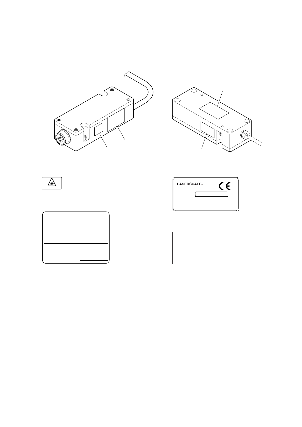
CAUTION
Use of controls or adjustments or perfomance of procedures other than those specified herein may result in hazardous radiation exposure.
e
w
q
r
q Laser Danger label
See Manual
w DHHS label
CERTIFICATION
PRODUCT COMPLIES WITH DHHS RULES 21
CFR SUBCHAPTER J APPLICABLE AT DATE
OF MANUFACTURE.
Magnescale Co., Ltd.
Shinagawa Intercity Tower A-18F, 2-15-1,
Konan, Minato-ku, Tokyo 108-6018, Japan
MANUFACTURED AT ISEHARA PLANT
Magnescale Co., Ltd.
2-933-725-
∗∗
e Specification label
B L 5 5
D C + 5 V S e r i a l N o .
Magnescale Co., Ltd.
* * * * *
* * * * * *
M A D E I N J A P A N
r FCC label
THIS DEVICE COMPLIES WITH PART 15 OF
THE FCC RULES. OPERATION IS SUBJECT TO
THE FOLLOWING TWO CONDITIONS :
(1)THIS DEVICE MAY NOT CAUSE HARMFUL
INTERFERENCE, AND
(2)THIS DEVICE MUST ACCEPT
ANY INTERFERENCE RECEIVED,
INCLUDING INTERFERENCE THAT MAY CAUSE
UNDESIRED OPERATION. *-***-***-**
BL55-RU
(E) (3)

Operating Precautions
• An antistatic cap and antistatic connector are attached to the connector plugs of the interface unit and
slider. Do not remove these until you are ready to connect the peripherals.
Also, after removing the antistatic cap and antistatic connector of the connector plug, be particularly
careful not to touch the connector pins. Touching the connector pins can damage the scale.
• The antistatic cap and antistatic connector can be reused after they are removed, and so be careful that
you do not lose them.
• Be sure that all connectors of the interface unit and slider are connected to the peripherals before
turning on the power switch. Never insert or remove the connectors while the power is turned on.
• Do not pull at the cable forcibly or bend it excessively. (Bending radius (inside) Static: 30 mm or more, Moving:
100 mm or more)
• Use the BL55-RU approximately 10 minutes after power is supplied to the unit, when the temperature of the
detector head reaches a stable state.
• The BL55-RU is a precision measuring instrument. Handle it with extreme care so that no excessive shock is
applied to it. For transport, be sure to pack it in the same way as it was packed at the time of purchase. Be sure
to always attach the antistatic cap and antistatic connector.
Notes on installation
Ta ke careful note of the following points when installing the scale unit to prevent noise and electromagnetic interference from other equipment.
• Do not pass the head cable and connection cable through the same duct as the power line.
• Install in a location that is at least 0.5 meters separated from sources of high voltage and large currents and
large power relays.
Notes on attachment location
• Attach the scale in a location as near as possible to the workpiece and measurement object of the machine.
• Use this product in an environment with an ambient temperature of 0 to 40 °C.
Do not attach it to a location that is exposed to direct sunlight or warm air or near sources of heat such as motors.
This could adversely affect the accuracy.
•Never place objects on top of the attached scale, rest your elbows or feet on the scale when using it, or apply an
excessive amount of pressure to the scale.
Notes on operating environment
If using the scale unit in environments q or w below, be sure to always take the following preventative measures.
If these measures are not taken, scale quality cannot be guaranteed.
q When using a water-based cutting fluid, performing machining where fine metal dust is produced, or
machining ceramic, fiberglass, and similar types of workpieces
w When installing on a device performing high-speed sliding over a specific area for extended periods of
time, such as a homing machine
• Attach in a location where the water-based cutting fluid and cuttings do not fall directly on the scale.
•Mount the scale cover so that the mist and particles from the water-based cutting fluid do not get inside the
scale.
• Inject clean air that passes through an air filter, mist separator, or other devices.
(4) (E)
BL55-RU

Notes on storage
• Do not store in locations with high temperatures or high humidity.
This could have an adverse effect on scale performance. Store in a location that is as dry as possible.
General Precautions
When using Magnescale Co., Ltd. products, observe the following general precautions along with those given
specifically in this manual to ensure proper use of the products.
• Before and during operations, be sure to check that our products function properly.
• Provide adequate safety measures to prevent damages in case our products should develop malfunctions.
• Use outside indicated specifications or purposes and modification of our products will void any warranty of the
functions and performance as specified of our products.
•When using our products in combination with other equipment, the functions and performance as noted in this
manual may not be attained, depending upon operating environmental conditions. Make full study of the compatibility in advance.
BL55-RU
(E) (5)

[For U.S.A. and Canada]
THIS CLASS A DIGITAL DEVICE COMPLIES WITH
PART15 OF THE FCC RULES AND THE CANADIAN
ICES-003. OPERATION IS SUBJECT TO THE
FOLLOWING TWO CONDITIONS.
(1) THIS DEVICE MAY NOT CAUSE HARMFUL
INTERFERENCE, AND
(2) THIS DEVICE MUST ACCEPT ANY
INTERFERENCE RECEIVED, INCLUDING
INTERFERENCE THAT
MAY CAUSE UNDERSIGNED OPERATION.
CET APPAREIL NUMERIQUE DE LA CLASSE A
EST CONFORME A LA NORME NMB-003 DU
CANADA.
(6) (E)
BL55-RU

Contents
1. Overview ......................................................................... 1-1
1-1. Introduction .................................................................................................. 1-1
1-2. Main Features ............................................................................................... 1-1
1-3. Information Specified when Placing Order.................................................. 1-1
1-4. Configuration ............................................................................................... 1-2
1-5. Series Models ............................................................................................... 1-3
2. Names and Functions of Parts ..................................... 2-1
2-1. Scale ............................................................................................................. 2-1
2-2. Interface Unit ............................................................................................... 2-2
3. Installing the Scale......................................................... 3-1
3-1. Installation Precautions ................................................................................ 3-1
3-1-1. Checking the Installation Direction ............................................ 3-1
3-1-2. Range of Movement Settings ...................................................... 3-2
3-1-3. Protecting the Head Cable ........................................................... 3-2
3-1-4. Attaching the Scale Cover ........................................................... 3-2
3-2. Required Items for Installation..................................................................... 3-3
3-3. Before Installation ........................................................................................3-4
3-4. Installation Procedure................................................................................... 3-4
3-4-1. Head Cable Connection............................................................... 3-4
3-4-2. Scale Unit Installation ................................................................. 3-5
3-4-3. Attaching the Slider..................................................................... 3-6
3-4-4. Removing the Slider Holder........................................................ 3-7
3-4-5. Checking after Installation .......................................................... 3-8
3-4-6. Signal Check ............................................................................... 3-9
3-4-7. Checking the Operating Range ................................................. 3-11
3-4-8. Securing the Head Cable ........................................................... 3-11
3-4-9. Removing the Scale................................................................... 3-12
3-5. Air Injection Procedure .............................................................................. 3-12
3-5-1. Installation ................................................................................. 3-12
3-5-2. Air Pressure Source ................................................................... 3-13
3-5-3. Supply Amount.......................................................................... 3-13
BL55-RU
4. Interface Unit .................................................................. 4-1
4-1. Installing the Interface Unit ......................................................................... 4-1
4-2. Removing and Attaching the Interface Unit Cover ...................................... 4-1
4-3. MODE Switch ..............................................................................................4-2
4-3-1. Detailed Description of MODE Switches ................................... 4-3
4-4. Changing the Settings .................................................................................. 4-4
4-4-1. Changing the Direction ............................................................... 4-4
4-4-2. Changing the Resolution ............................................................. 4-4
4-4-3. Setting the Reference Point Output Signal Width ....................... 4-4
4-4-4. Adjusting the Reference Point .................................................... 4-5
4-4-5. Setting the Reference Point Output and Reference Point
Detection Direction ..................................................................... 4-6
4-4-6. Setting the Alarm Reset Mode .................................................... 4-7
4-5. Scale Signal Output ...................................................................................... 4-7
4-5-1. A/B and Z Signal Output Specifications .....................................4-7
4-5-2. Analog Output Specifications ..................................................... 4-8
(E) i

5. Input/Output Connectors............................................... 5-1
5-1. Connectors.................................................................................................... 5-1
5-2. Connection Specifications............................................................................ 5-2
5-2-1. A/B Signal Output Type .............................................................. 5-2
5-2-2. Analog Output Type .................................................................... 5-4
6. Main Specifications........................................................ 6-1
7. Dimensions ..................................................................... 7-1
8. Trouble Prevention ......................................................... 8-1
ii (E)
BL55-RU

1. Overview
1-1. Introduction
The BL55-RU series is a shielded-type LASERSCALE with integrated detector containing a built-in reference
point. The scale outputs A/B and Z signals, or analog and reference point signals when DC
+5 V ±5 % is supplied to the interface unit.
The scale signals have been electrically pre-adjusted at the factory, and so the user only needs to make the
reference point signal setting when installing the scale.
1-2. Main Features
■ Head signal cycle of 0.4 µm allows the interpolation error to be disregarded
■ Optical integrated circuits employing the latest semiconductor technology are used to achieve a compact
and low-energy design
■ Internal non-contact structure allows the complete elimination of the causes of errors
■ Maximum speed: 3,000 mm/s (analog output)
1-3. Information Specified when Placing Order
• Reference point position
The reference point position is the distance from the measuring length end. Positions less than 4 mm from
the measuring length edges cannot be designated.
• Reference point detection direction
Refer to section 4-4-4 (Fig. 4-4).
• Cable length
The length can be specified in 0.1 m units in the range from 0.5 to 3.0 m.
• Scale material
The low-expansion material neoceram can be specified.
BL55-RU
(E) 1-1
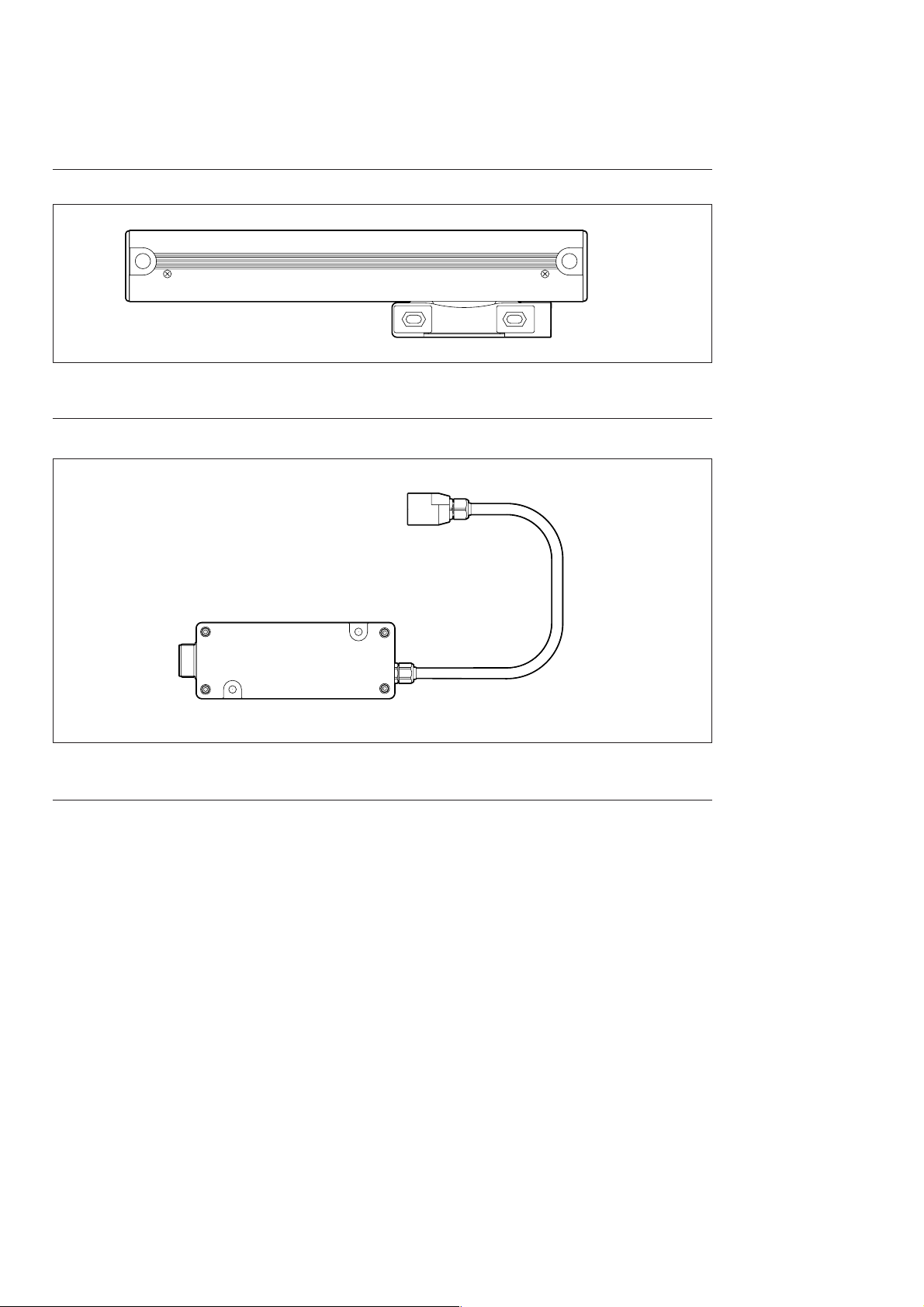
1-4. Configuration
Scale unit and slider ..................................................... 1
Fig. 1-1
Interface unit and head cable....................................... 1
Fig. 1-2
Accessories
Hex. socket-head cap screw M8 × 25 ....................................................................................................... 2
Hex. socket-head cap screw M4 × 25 ....................................................................................................... 4
Hex. socket-head cap screw M4 × 12 ....................................................................................................... 2
Hex. socket-head cap screw M2.6 × 16 .................................................................................................... 2
Hex. socket-head cap screw M4 × 10 ....................................................................................................... 6
Spring washer: Nominal size 4 ..................................................................................................................... 4
Plain washer: Nominal size 4 ....................................................................................................................... 2
Hex. nut: Nominal size 4 .............................................................................................................................. 2
Spacer t = 0.05 ............................................................................................................................................ 2
Spacer t = 0.1 .............................................................................................................................................. 3
Cable clamp .................................................................................................................................................. 2
Hex. socket-head half-union ......................................................................................................................... 3
1-2 (E)
BL55-RU
1-5. Series Models
Model name Measuring length Number of foot plates
BL55-007RU •••••• 70 mm 0
BL55-012RU •••••• 120 mm 0
BL55-017RU •••••• 170 mm 0
BL55-022RU •••••• 220 mm 0
BL55-027RU •••••• 270 mm 0
BL55-032RU •••••• 320 mm 0
BL55-037RU •••••• 370 mm 0
BL55-042RU •••••• 420 mm 0
BL55-047RU •••••• 470 mm 0
BL55-052RU •••••• 520 mm 1
BL55-057RU •••••• 570 mm 1
BL55-062RU •••••• 620 mm 1
BL55-072RU •••••• 720 mm 1
BL55-077RU •••••• 770 mm 1
BL55-082RU •••••• 820 mm 1
BL55-087RU •••••• 870 mm 1
BL55-092RU •••••• 920 mm 1
BL55-102RU •••••• 1020 mm 2
***
RU
Tab le 1-1
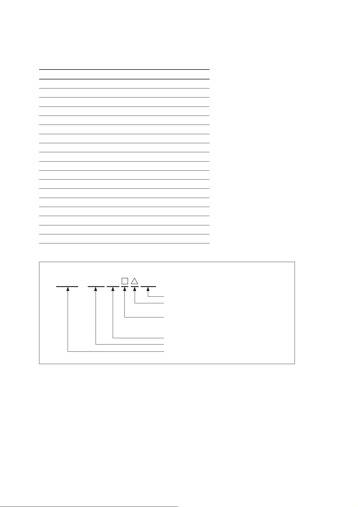
K##BL55−
Individual number
Scale accuracy
Output format
Shielded-type scale with reference point
Measuring length (cm)
Model
Fig. 1-3
±
2.5 µm
5 :
6 : ±4.5 µm
F: A/B signal output (0.1/0.05 µm)
G: A/B signal output (0.02/0.01 µm)
H: Analog output
BL55-RU
(E) 1-3

1-4 (E)
BL55-RU
2. Names and Functions of Parts
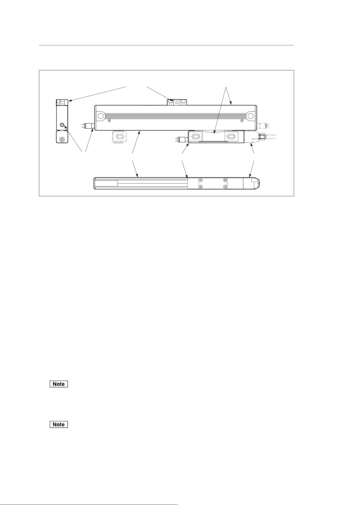
2-1. Scale
e Foot plate
r Air inlet w Scale unit q Slider
Fig. 2-1. Scale
t Model name and Serial No.
BL55-RU
XXXXXX
y Connector
q Slider
The slider has a built-in detector head. The slider is secured in place by the slider holders at shipping.
w Scale unit
The scale unit incorporates a high-accuracy LASERSCALE. It is protected by an aluminum cover.
e Foot plate
This is used to secure the scale in place.
The number of attached foot plates varies depending on the scale measuring length.
Measuring length of 470 mm or less ........................ None
Measuring length of 520 mm to 920 mm ................. 1
Measuring length of 1020 mm .................................. 2
r Air inlet
This is used when air is injected.
To inject air, remove the hex.socket-head set screws covering the inlets, and then attach the hex. sockethead half-union.
t Model name and Serial No.
This indicates the model name and serial number.
Be sure to always use scale and interface units that have matching serial numbers.
y Connector
Connect the head cable for linking with the interface unit.
The connector has an antistatic connector. Do not remove this connector until you are ready to connect
the interface unit.
Also, after removing the antistatic connector, be particularly careful not to touch the connector pins.
Touching the connector pins can damage the scale.
BL55-RU
(E) 2-1
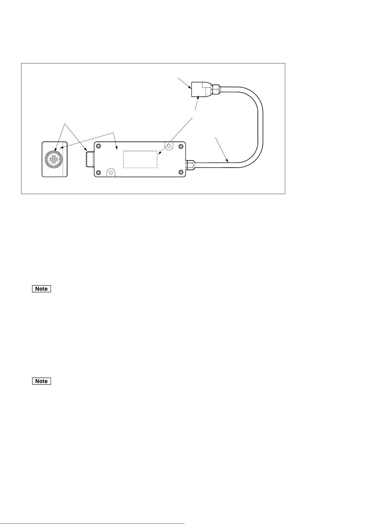
2-2. Interface Unit
w Scale connector
BL55-RU
XXXXXX
r Input/output connectors
q Interface unit
Fig. 2-2. Interface unit and cable
Serial No.
e Head cable
q Interface unit
The detector converts the signals from the scale into A/B and Z signals or analog and reference point
signals.
Each signal is output from the input/output connector by supplying DC +5 V ±5 % power.
w Scale connector
This connector joins the interface unit to the slider.
The serial number of the interface unit is printed on this connector.
• Before connecting the connector, be sure to always check that the power supplied to the interface unit
is off.
• Be sure to always use scale and interface units that have matching serial numbers.
e Head cable
The head cable connects the scale and interface unit.
r Input/output connectors
Scale signals and reference point signals are output when DC +5 V ±5 % is supplied as the power
source.
• Be sure to always use a power supply of DC +5 V ±5 %.
• The input/output connectors have an antistatic cap. Do not remove this cap until you are ready to
connect the peripherals.
Also, after removing the antistatic cap, be particularly careful not to touch the connector pins. Touching
the connector pins can damage the scale.
2-2 (E)
BL55-RU
3. Installing the Scale
3-1. Installation Precautions
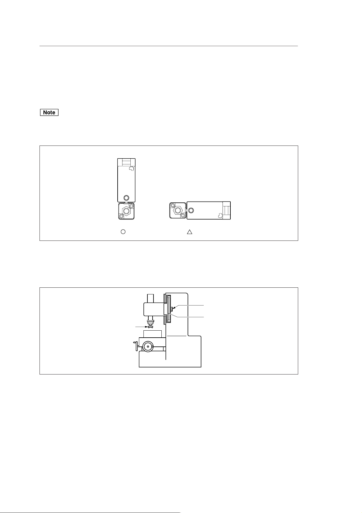
3-1-1. Checking the Installation Direction
Check that the scale is installed in the positional relationship shown in Fig. 3-1.
Except when installed on a vertical axis, only the orientation in Fig. 3-1 should be used.
If installing on a machine tool or other equipment where powder and dust occur, install using the A orientation
since this allows usage of cutting fluid and prevents the intrusion of cutting dust.
Install using the B orientation only in other situations when virtually no foreign objects can enter the scale.
A
B
OK
Fig. 3-1. Scale installation direction
Conditional
Installing on vertical axis
If installing on a machine tool or other equipment where powder and dust occur, install so that the scale
slider is facing the opposite direction of the machining tool (cutting tool).
Slider
Scale unit
Cutting tool
Fig. 3-2. Scale installation position and direction for the vertical axis
BL55-RU
(E) 3-1
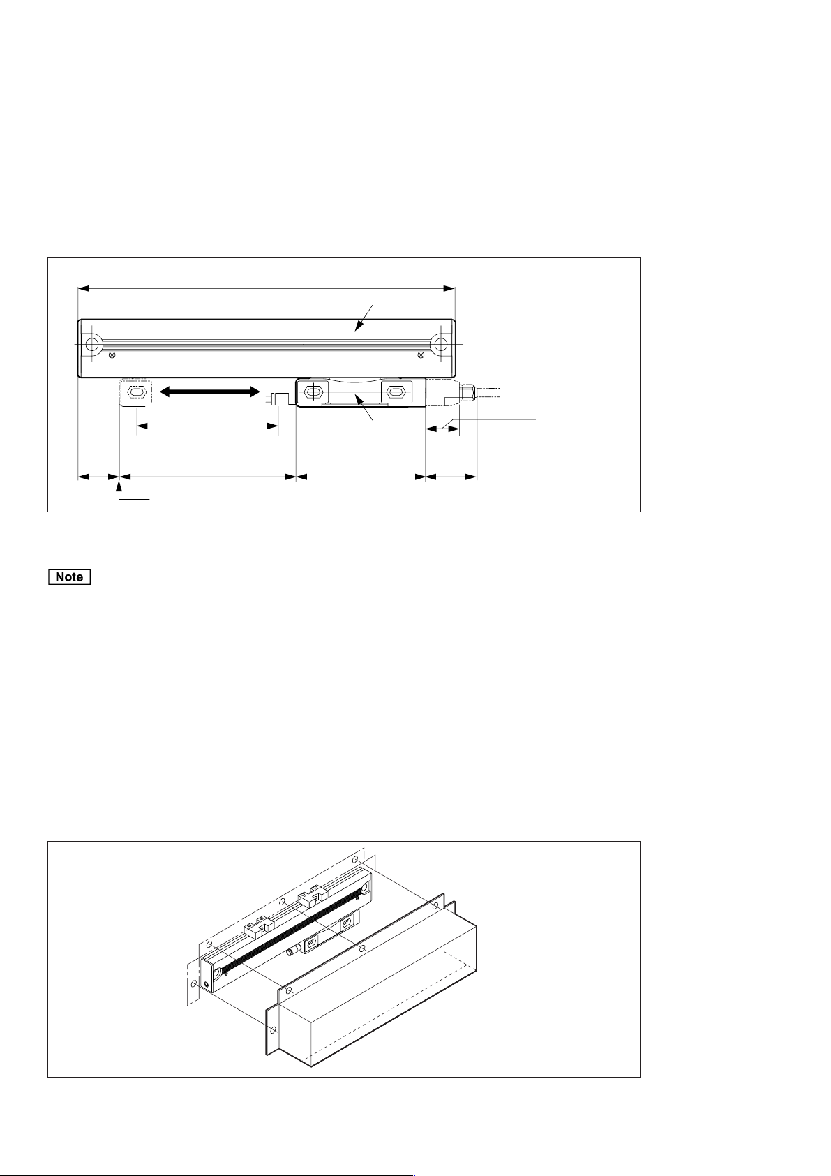
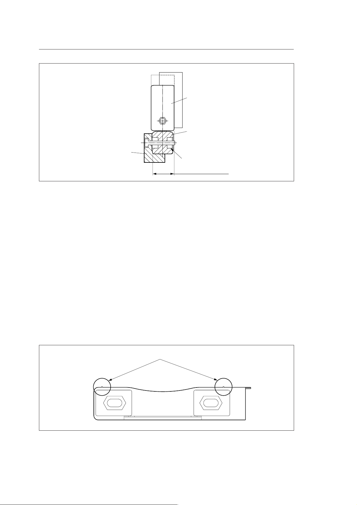
3-1-2. Range of Movement Settings
As shown in Fig. 3-3, when the head cable is drawn out to the right side, the point where the distance from
the slider left end and scale unit left end is 28.5 mm is considered the left end movable limit. Although the
slider or scale unit can move an amount equal to the measuring length from this left end movable limit, there
is almost no margin at both ends. Be particularly careful that the machine movable length falls within the
scale measuring length.
28.5
(1.122")
Total length = Measuring length (L)
Machine movable length
Measuring length (L)
Left end movable limit
Fig. 3-3. Operation range
+ 137 (5.394")
Scale unit
Slider
88 (3.465")
Head cable drawing out
23 (0.906")
35
(1.378")
Unit: mm (inch)
The detector head will be damaged if the slider or scale unit is moved past the measuring length.
A mechanical limiting mechanism (such as a stopper) is needed for machines that exceed the measuring
length (movable range) of the scale. Be sure to install this type of device before installing the scale.
3-1-3. Protecting the Head Cable
The head cable and slider are designed to be attached and removed by screws.
Be careful not to pull strongly on the cable or repeatedly bend the cable, since this can damage it.
3-1-4. Attaching the Scale Cover
To maintain scale performance, attach a protective cover to the scale as shown in Fig. 3-4 when the scale is
directly exposed to chips and cutting fluid during use.
Fig. 3-4. Example of attaching scale cover
3-2 (E)
BL55-RU

3-2. Required Items for Installation
Accessories Quantity
Hex. socket-head cap screw M8 × 25 For Scale installation 2
Hex. socket-head cap screw M4 × 25 For Slider installation 2
For foot plate installation 2
(Measuring length of 470 mm or less:
No foot plate; measuring length of 520 mm
to 920 mm: 1 foot plate; measuring length
of 1020 mm: 2 foot plates)
Hex. socket-head cap screw M2.6 × 16 For head cable fastening 2
Hex. nut Nominal size 4 2
Hex. socket-head cap screw M4 × 10 For cable clamp 6
Spring washer nominal size 4 For slider installation 2
Spring washer nominal size 4 For foot plate installation 2
Cable Clamp For head cable fastening 2
Spacer t = 0.05 For slider installation 2
t = 0.1 For slider installation 3
Hex. socket-head half-unions For injecting air 3
Plain washers nominal size 4 2
Hex. socket-head cap screw M4 × 12 For interface unit 2
In addition to the accessories, obtain the following parts and tools.
Scale installation bracket (for sides A and B) 1 - 2
Slider installation bracket (for side C) 1
0.01 mm pick tester (or dial gauge) 1 - 2
Dial gauge stand 1
Oscilloscope 1
Capable of 2-quadrant X-Y display
Input sensitivity : DC 0.1 V/DIV
X-Y frequency band : 1 MHz or more
Allen wrench M2.6 (Opposite side: 2 mm) 1
Allen wrench M4 (Opposite side: 3 mm) 1
Allen wrench M8 (Opposite side: 7 mm) 1
Tap M4 1
Tap M8 1
Drill φ 3.2 1
Drill 6.8 1
Electric drill 1
Liner/spacer (0.05 - 0.2 t) Small amount
No.2 Phillips screwdriver 1
BL55-RU
(E) 3-3
3-3. Before Installation
• Do not disassemble parts other than those designated when performing work.
• The inside of the scale contains precision optical parts and electrical parts. Therefore, applying excessive
pressure to the unit can seriously harm the performance and service life of the scale. Be careful not to
apply excessive pressure to the scale when proceeding with the work.
• The inside of the interface unit contains electrical parts that have been installed and adjusted to precision.
Perform operation while being careful not to apply excessive pressure to the interface unit.
• Support the scale unit/slider and the interface unit and head cable whenever carrying these parts. Do not
carry these parts by holding only onto the head cable.
• Properly ground the scale unit housing/slider, the interface unit case, and power supply frame ground.
3-4. Installation Procedure
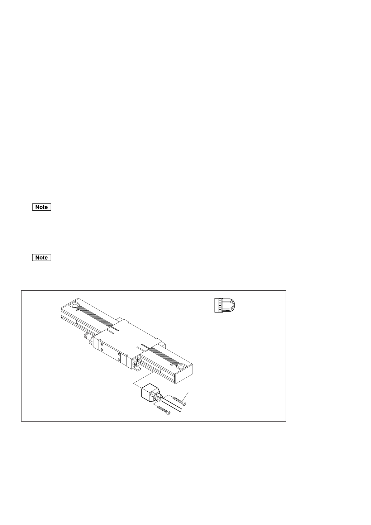
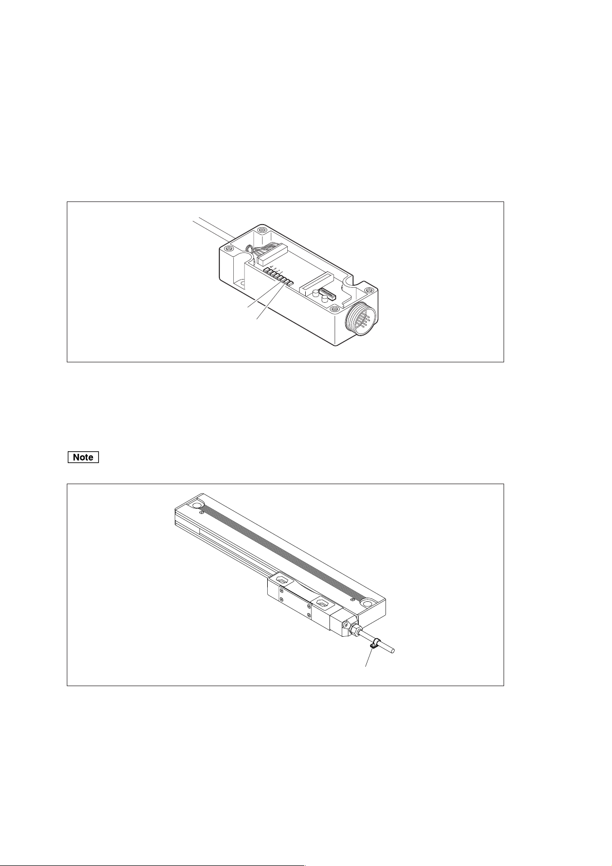
3-4-1. Head Cable Connection
1. Remove the antistatic connector attached to the slider.
The antistatic connector can be reused after it is removed, and so be careful that you do not lose it.
2. Connect the scale connector of the head cable to the slider, and then secure using the hex. socket-head
screw.
Screw/Tightening torque:...... M2.6 × 16: 2 pcs. / 0.65 N · m
Before connecting the connector, be sure to always check that the power supplied to the interface unit is
off. Never insert or remove the connector while power is supplied to the interface unit. This could
damage the scale unit.
Antistatic connector
M2.6 × 16
Fig. 3-5. Head cable attachment
3-4 (E)
BL55-RU
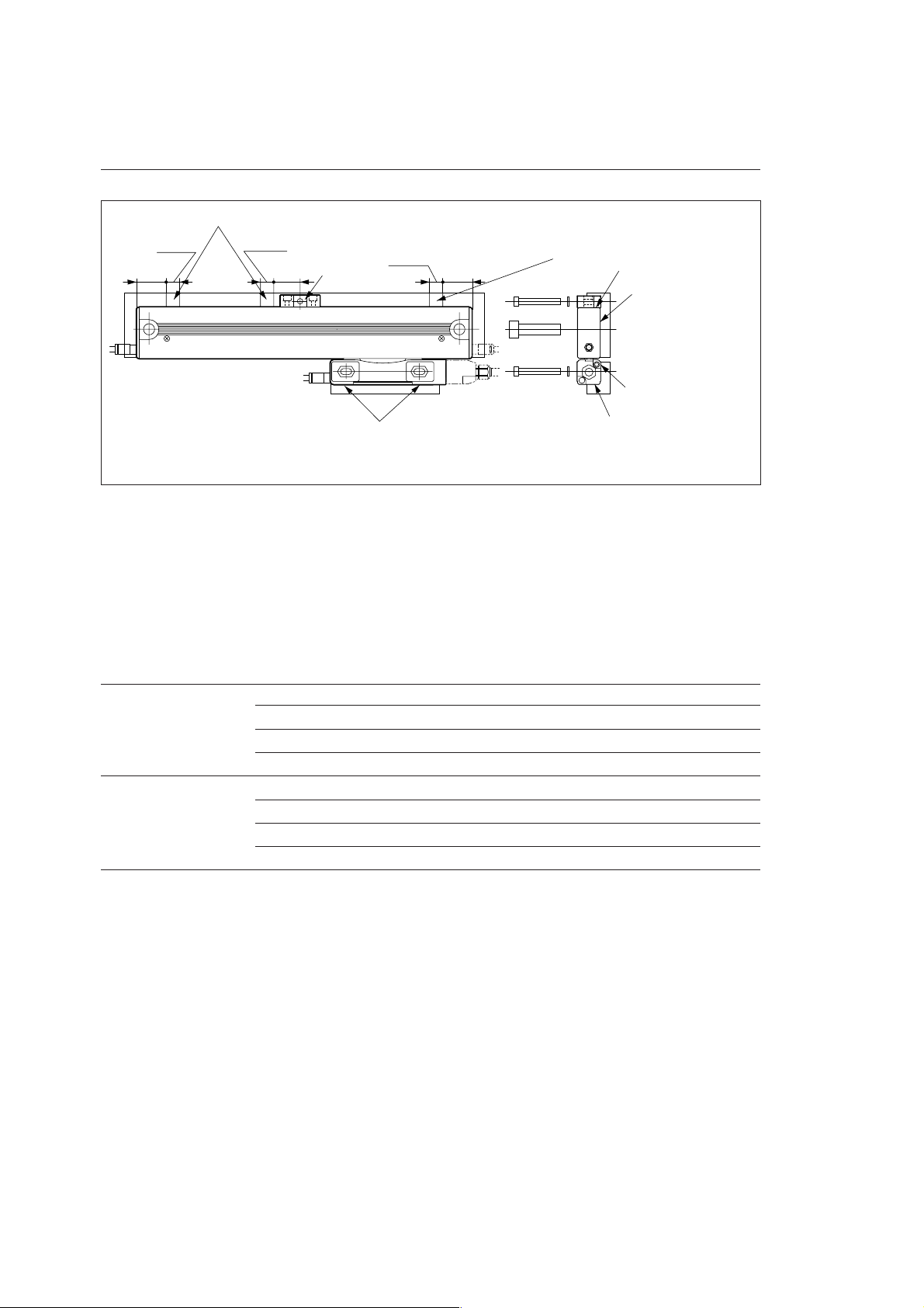
3-4-2. Scale Unit Installation
Parallelism and flatness of the alignment surface
Alignment position
10
(0.394")
25
(0.984")
10
(0.394")
(0.787")
20
Foot plate
10
(0.394")
(0.984")
25
Alignment position
A (alignment surface)
B (alignment surface)
C (alignment surface)
Alignment position
Fig. 3-6
D (alignment surface)
Unit: mm (inch)
Attach the scale unit so that the parallelism and flatness of the alignment surface are as shown in Table 3-1.
Scales with measuring length of 470 mm or less (without foot plate)
Screw/Tightening torque:........ M8 × 25: 2 pcs. / 22 N · m
Scales with measuring length of 520 mm or more (with foot plate)
Screw/Tightening torque:........ M8 × 25: 2 pcs. / 22 N · m
Screw/Tightening torque:........ M4 × 25: 1 or 2 pcs. / 2.7 N · m
Washer: .................................... Spring washers with nominal size 4: 1 or 2 washers
Measuring length of Side A flatness 0.1 mm (0.0039") or less
70 or 120 mm
Measuring length of Side A flatness 0.1 mm (0.0039") or less
170 mm or more
Side B flatness 0.05 mm (0.0019") or less
Parallelism with respect to side A machine runway 0.05 mm (0.0019") or less
Parallelism with respect to side B machine runway 0.05 mm (0.0019") or less
Side B flatness 0.05 mm (0.0019") or less
Parallelism with respect to side A machine runway 0.1 mm (0.0039") or less
Parallelism with respect to side B machine runway 0.1 mm (0.0039") or less
Tab le 3-1
Attach so that the alignment position for the side A has the range shown in Fig. 3-6. The values for the
allowable range in Table 3-1 assume that there are no sudden shifts on the surface.
BL55-RU
(E) 3-5
3-4-3. Attaching the Slider
Parallelism/flatness of alignment surface
A (alignment surface)
0.1 (0.004")
±
B (alignment surface)
Scale unit
61.5 (2.421")
D (alignment surface)
C (alignment surface)
Slider unit
1 (0.039")
Fig. 3-7
±
0.1 (0.004")
Unit: mm (inch)
Attach the slider so that the parallelism and flatness of the alignment surface are as shown in Table 3-2.
Screw/Washer:............... M4 × 25: 2 pcs. / Spring washers with nominal size 4: 2 washers
Tightening torque: ......... 2.7 N · m
Side C parallelism 0.02 mm (0.00078") or less
Side D parallelism 0.05 mm (0.00196") or less
Parallelism with respect to Side C machine runway 0.03 mm (0.00118") or less
Parallelism with respect to Side D machine runway 0.05 mm (0.00196") or less
Distance between Side B and Side C (step) 1 (0.039") ±0.1 (0.004") mm
Distance between Side A and Side D 59 (2.323") ±0.1 (0.004") mm
Tab le 3-2
When securing the slider to the mounting bracket, be sure to lift the slider side and move the slider above the
mounting bracket. If the machine is moved to perform positioning, the slider will contact the mounting
bracket, and this can damage the scale unit.
3-6 (E)
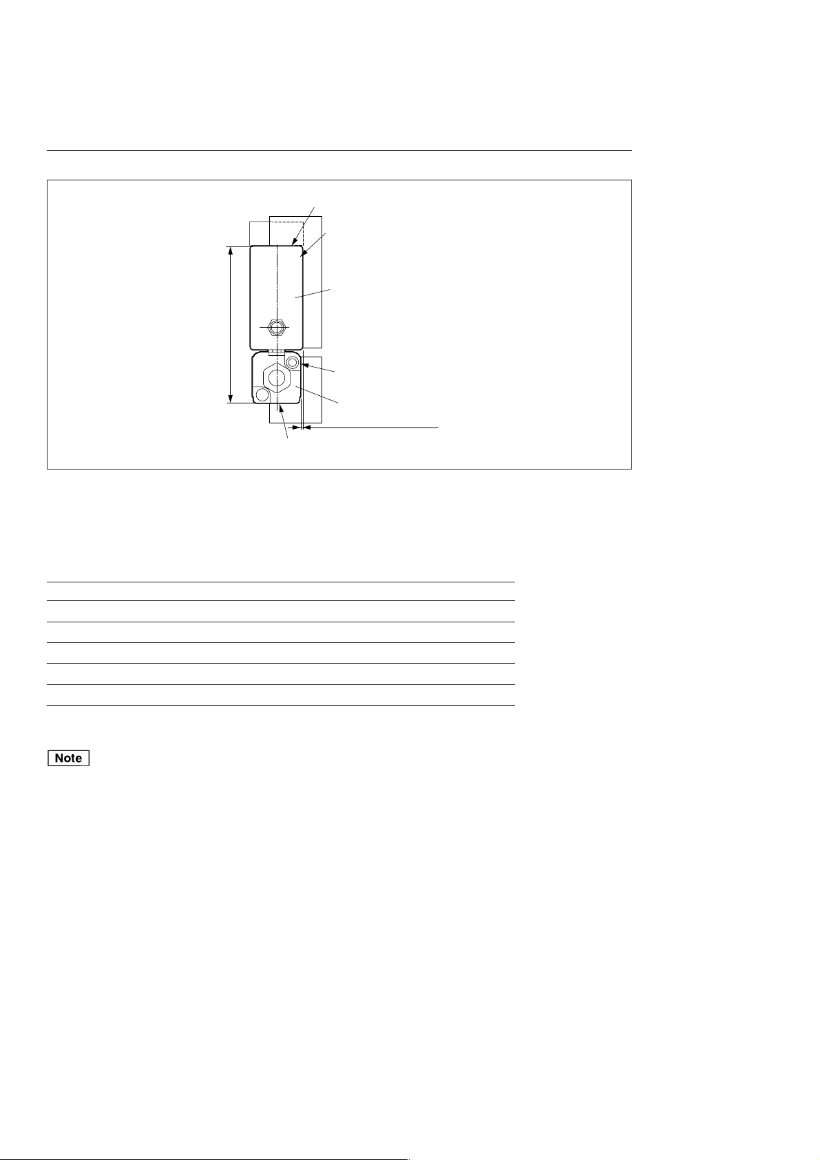
BL55-RU
Mounting brackets to the slider top
Mounting bracket
Scale unit
Slider unit
M4 nut
19 (0.748") ±0.1 (0.004")
Fig. 3-8
Unit: mm (inch)
Align the slider top and mounting bracket, and adjust the mounting bracket so that the distance from the
alignment surface is 19 ±0.1 mm. Make the parallelism and flatness of the alignment surface as shown in
Table 3-2.
Washer/Nut: .......................... Plain washer with nominal size 4: 2 washers/Hex. nuts with nominal size 4: 2
nuts
Screw/Tightening torque: ..... M4 × 25: 2 pcs. / 2.7 N · m
3-4-4. Removing the Slider Holder
Remove the slider holder after attaching the slider.
The slider holder can be removed from the slider with a one-touch operation.
There is a protrusion on the scale unit side of the slider. The slider holder fits into this protrusion. Use the
following procedure to remove the slide holder.
1 Pull out the slider holder in the lengthwise direction so that the protrusion on the scale unit side is passed
over, and then separate the slider and slider holder.
BL55-RU
Protrusion
Scale unit sideScale unit side
Fig. 3-9
(E) 3-7
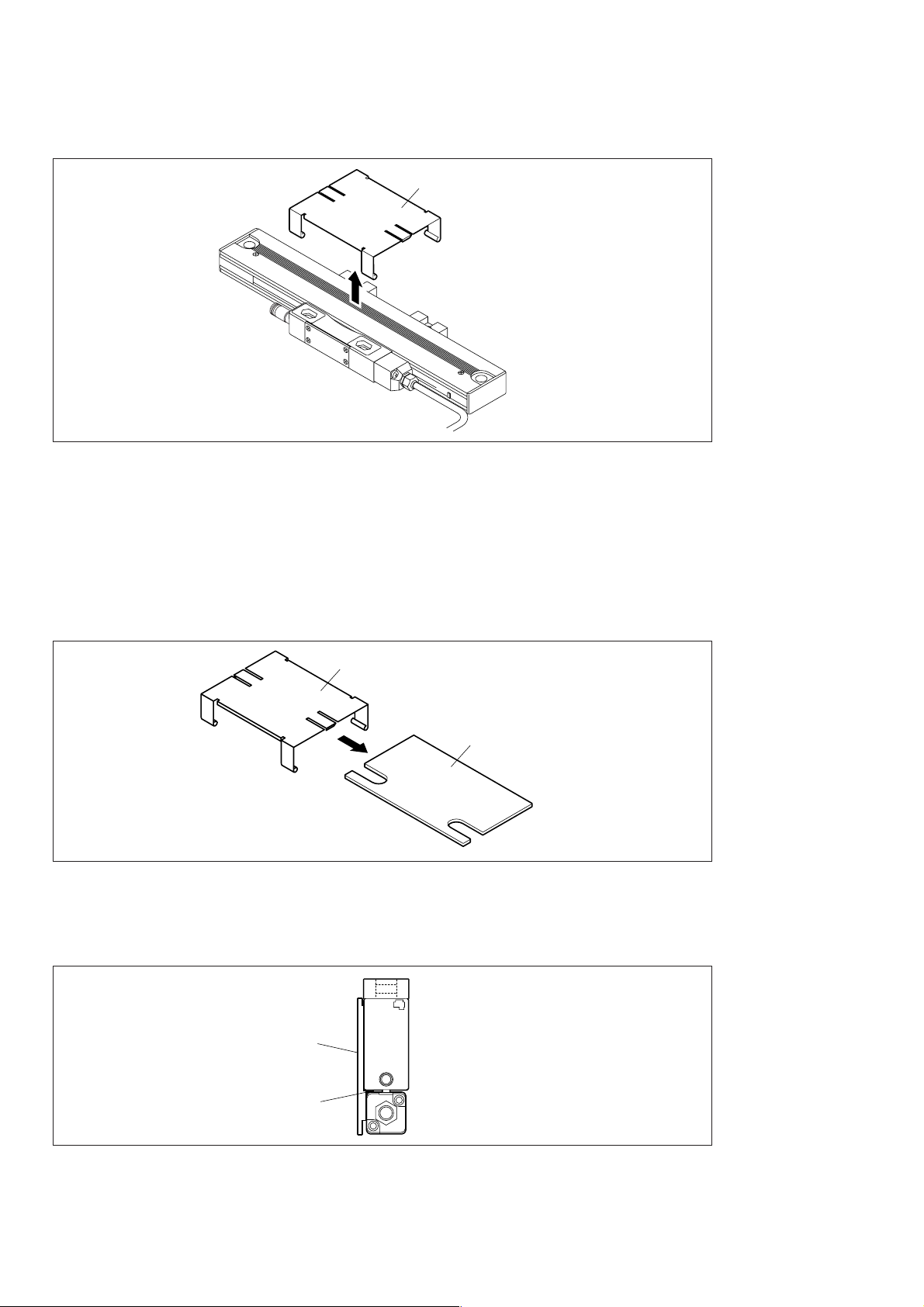
2 Lift up the slider holder over the scale unit.
Slider holder
Fig. 3-10
3-4-5. Checking after Installation
Once the scale is installed, check the installation state. Use the slider holding plate of the slider holder as a
checking tool.
1 Separate the slider holder removed in section 3-4-4 into the spring holder and slider holding plate.
Spring holder
Slider holding plate
Fig. 3-11
2 Check that the rib section of the slider holding plate fits smoothly into the space between the scale unit
and slider. (Thickness of the rib section of the slider holding plate: 1 mm)
Slider holding plate
Rib
Fig. 3-12
The scale and slider were not attached properly if the slider holding plate does not fit or rattles noticeably.
The scale and slider must be attached again from the beginning.
3-8 (E)
BL55-RU
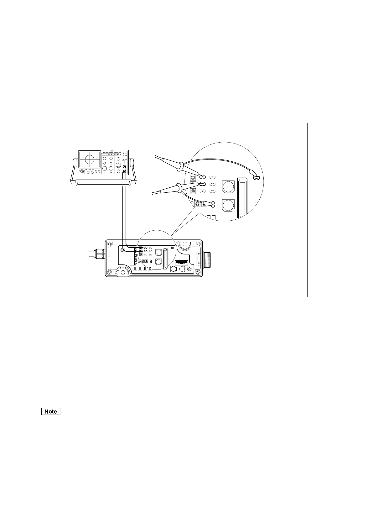
3-4-6. Signal Check
Check that the interface unit is turned off.
Refer to section 4-2 for removing and attaching the cover of the interface unit.
1 Connect the CH1 probe of the oscilloscope to the TP3 and TP8 check pins of the interface unit.
2 Connect the CH2 probe of the oscilloscope to the TP2 and TP7 check pins of the interface unit.
Oscilloscope
CH1
TP6
CH2
CH1CH2
TP3
TP2
TP1 TP4
TP5
TP8
Probe
TP3 TP6
TP2 TP5
TP1 TP4
Signal adjustment section-datailed view
Interface unit
TP8
TP7
Fig. 3-13
TP7
3 Set the TIME/DIV switch to the X-Y mode.
4 Set the deviation sensitivity (VOLTS/DIV) of CH1 and CH2 to 0.5 V/DIV.
5 Set the input coupling switches of CH1 and CH2 of the oscilloscope to GND and adjust the oscilloscope
to locate the signal at the bottom left of the screen.
6 Set the input coupling switches of CH1 and CH2 of the oscilloscope to DC.
7 Turn the interface unit’s power on.
Be sure that the interface unit is turned off before attaching or removing the probe of the oscilloscope.
BL55-RU
(E) 3-9
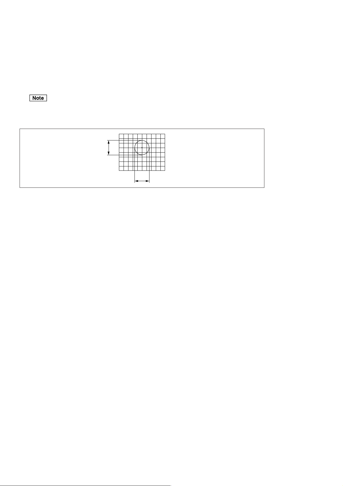
8 Move the scale, and make sure that the amplitudes A and B (see Fig. 3-14) of the Lissajous’ figure are
within the range of the specified values over the entire length.
<Specified values>
A/B signal output type ..... Output format F : Amplitude 0.7 Vp-p to 1.3 Vp-p
Output format G : Amplitude 0.8 Vp-p to 1.2 Vp-p
Analog output type........... Output format H: Amplitude 0.3 Vp-p to 0.6 Vp-p
The center of the Lissajous’ figure is 2.5 V.
If the reference value outputs are not obtained or the center of the Lissajous’ figure is not at 2.5 V, refer
to the attached “Attaching the Slider” (see page 3-6).
Lissajous
A
B
Fig. 3-14
3-10 (E)
BL55-RU
3-4-7. Checking the Operating Range
After mounting the scale unit and slider, be sure to always move the machine over its entire length to check
that the machine movement range is within the scale measuring length. During this check, make sure that
LED on the interface unit does not indicate an alarm. (A/B phase output types only) Refer to section 4-2 for
removing and attaching the cover of the interface unit.
Be careful that the scale movement range does not exceed the scale measuring length + range of movement.
If it does, the scale can be damaged.
Level alarm
Speed alarm
Fig. 3-15
3-4-8. Securing the Head Cable
Secure the head cable with a cable clamp so that it does not get in the way of movement or operation.
The cable clamps are secured using a M4 × 10 hex. socket-head cap screw.
Note that the wiring should be made to allow enough room for machine movement during operation.
Secure with M4 × 10 hex. socket-head cap screw
Cable clamp (supplied)
BL55-RU
Fig. 3-16
(E) 3-11
3-4-9. Removing the Scale
Use the following procedure to remove a scale that has been installed on a machine.
1 Use the slider holder to secure the slider to the scale unit.
Be sure to always use the slider holder.
2 Remove the slider attachment screws.
3 Remove the scale unit attachment screws.
3-5. Air Injection Procedure
Chips, cutting oil, and other substances generated by cutting can frequently be scattered in the area around
the scale unit, especially when it is installed on a machine tool. Even when not using a machine tool, air
should be injected to the scale when installed on machines generating dust or when dust is prevalent in the
operating environment.
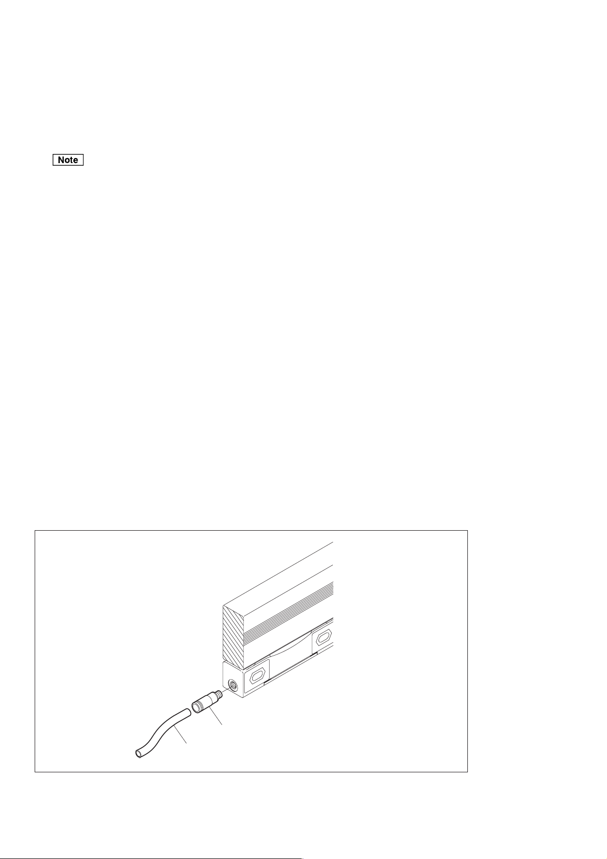
3-5-1. Installation
There are a total of three air inlets, one each on both sides of the scale unit and on the slider.
Supply air to all of the air inlets.
1 Remove the hex. socket head cap screws in the air inlets.
2 Wrap the sealing tape (obtained by customer) around the screw section of the supplied hex. socket-head
half-unions, and then screw into the air inlets.
Tightening torque: 1.5 N · m
3 Press a tube (available commercially, external diameter: 4 mm) into the hex. socket-head half-union.
3-12 (E)
Union
Outside of suitable tube
Fig. 3-17
BL55-RU
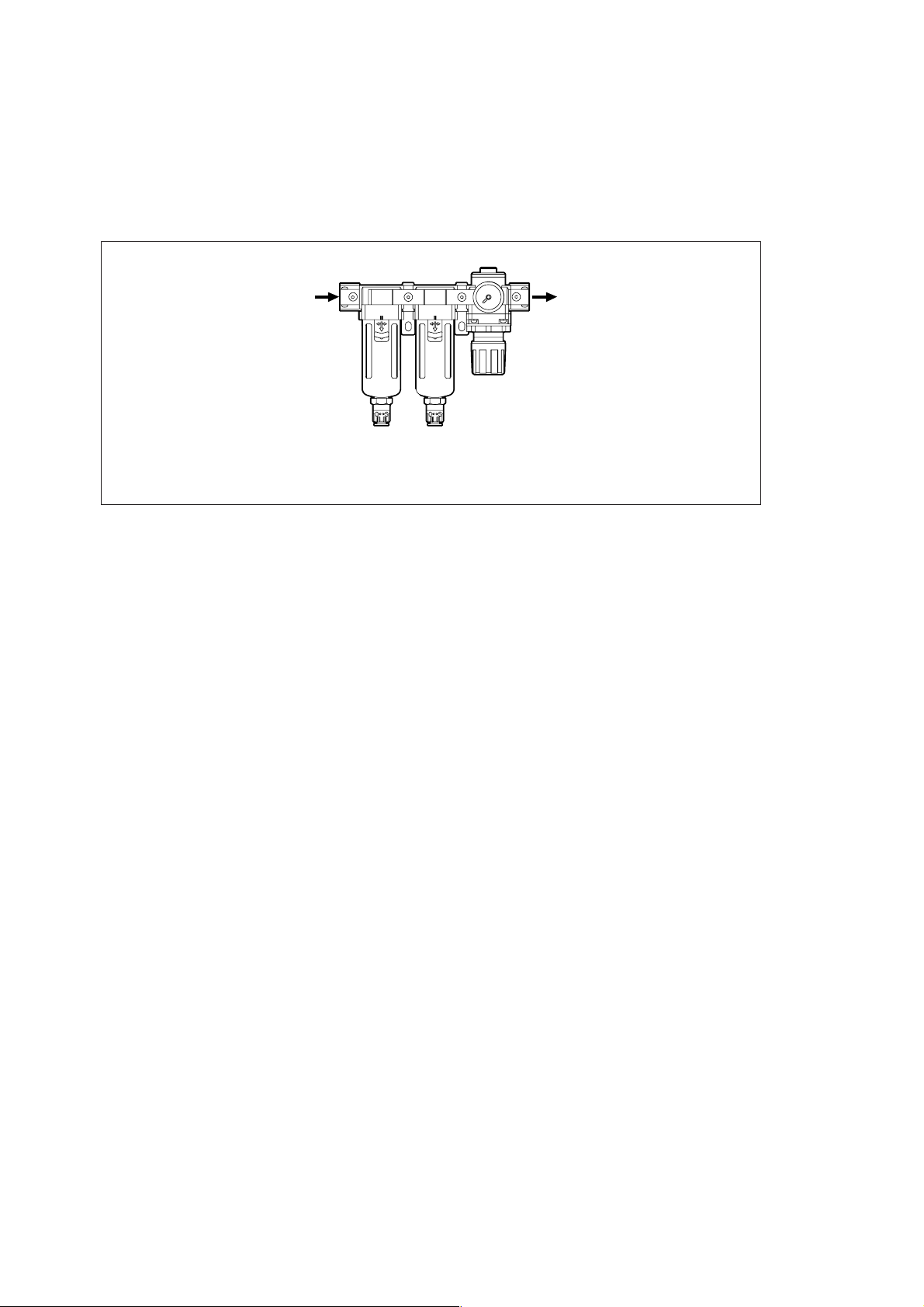
3-5-2. Air Pressure Source
Whenever air is supplied to the scale from an air pressure source, the air should always pass through a filter
(5 µm), mist separator (0.3µm), and regulator to remove any dust, mist, and other foreign substances. Sufficient
care should be taken since foreign substances entering inside the scale can cause a breakdown of the scale.
OUTIN
Regulator
Filter
5 µm
Mist
separator
0.3 µm
Fig. 3-18
3-5-3. Supply Amount
Air should be supplied to the scale at a pressure of 19.6 kPa per scale. Note that the pressure of the supply
section may be reduced due to the pipe length or layout even if the setting at the regulator is 19.6 kPa.
BL55-RU
(E) 3-13

3-14 (E)
BL55-RU
 Loading...