

Page 1

LaserSpeed LS8000-3
INSTRUCTION HANDBOOK
- installation, setup and technical reference (for qualified personnel only)
www.betalasermike.com
Manual Part Number: 93463 • Manual Drawing Number: 0921-01561 • English • Revision A• © Copyright Sep 2007
Page 2
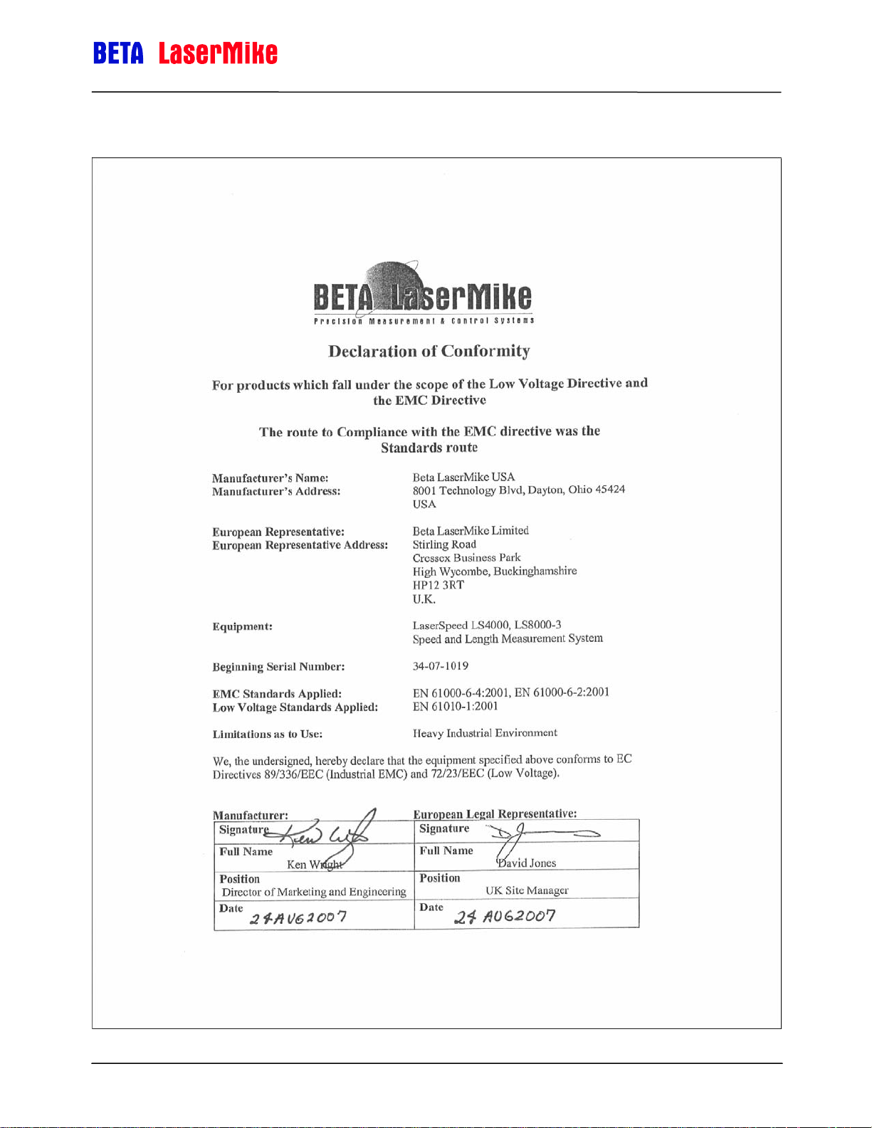
Declaration of Conformity
LaserSpeed 8000-3 Instruction Handbook
Contents
Part No. 93463 / Drawing No. 0921-01561 Page 2 of 221 Revision A (Sep 2007)
Page 3

LaserSpeed 8000-3 Instruction Handbook
Contents
Contents ...............................................................................................................................3
Proprietary Statement..........................................................................................................7
European Commission Requirements................................................................................8
Safety Information................................................................................................................9
Intended Use .......................................................................................................................................9
Laser Classification ...........................................................................................................................10
Laser Safety Precautions ..................................................................................................................11
Labels and Safety Features ..............................................................................................................12
LS8000-3 Labels.....................................................................................................................12
LS8000-3E Labels ..................................................................................................................13
LS8000-3X Labels ..................................................................................................................13
Introduction ........................................................................................................................14
System Overview................................................................................................................14
Principle of Operation ........................................................................................................................14
Contents
Installing the System .........................................................................................................16
Mounting the Gauge ..........................................................................................................................16
Mounting Distance ..................................................................................................................17
Laser Safety............................................................................................................................17
Environmental Conditions.......................................................................................................17
Ambient Temperature ................................................................................................17
Coolant ......................................................................................................................17
Air Wipe / Quick Change Window .............................................................................18
Steam & Mist .............................................................................................................18
Mounting Location ..................................................................................................................19
Twinner Lines .........................................................................................................................20
Aligning the Gauge ............................................................................................................................20
Aligning the Gauge ............................................................................................................................21
Gauge Orientation ..................................................................................................................23
Connecting Power to the Gauge .......................................................................................................24
Connecting to Outputs.......................................................................................................................25
LS8000-3 25-Pin Connector Pinout........................................................................................26
LS8000-3 9-Pin Connector Pinout..........................................................................................27
LS8000-3 M12 Connector Pinout ...........................................................................................27
LS8000-3E/LS8000-3X Connector Pinout..............................................................................28
LS8000-3E/LS8000-3X Breakaway Cable Pinout ..................................................................30
Maximizing Performance ...................................................................................................................31
Material Present Adjustment ..................................................................................................32
Material Present Dropout Time Selection...............................................................................32
Validation Time Limit Selection ..............................................................................................32
Starting/Ending Length Correction .........................................................................................33
Interfacing with the LS8000-3............................................................................................ 34
LS8000-3 Interface Connectors ........................................................................................................34
DB25 Connector .....................................................................................................................35
RS-232 Transmit and Receive (Pins 1-2)..................................................................36
High Speed Pulse Output (Pins 3, 5, 7, 9) ................................................................37
User Scaleable Pulse Output (Pins 15, 4, 6, 8).........................................................38
Part No. 93463 / Drawing No. 0921-01561 Page 3 of 221 Revision A (Sep 2007)
Page 4

LaserSpeed 8000-3 Instruction Handbook
Contents
Differential vs. Single Ended Pulse Outputs..............................................................38
Quadrature Output Phase Relationships...................................................................39
Quadrature Outputs at Extremely Low Pulse Frequencies .......................................41
Material Present Input (Pin 10)..................................................................................43
Connecting Material Present Switches......................................................................46
Signal Grounds (Pins 11, 19, 21) ..............................................................................49
Measurement Direction Input (Pin 14).......................................................................51
Laser Interlock (Pin 16) .............................................................................................52
Shutter Control (Pin 17) .............................................................................................53
Length Reset Input (Pin 18).......................................................................................53
User V
Index (Printer) Pulse Output (Pins 22-23) .................................................................55
+24V
DB9 Connector .......................................................................................................................56
RS-422 Transmit (+/-) and Receive (+/-) (Pins 1-4) ..................................................56
Analog Output Voltage/Ground (Pins 6-7).................................................................57
Measurement Synchronization Input (Pins 8-9) ........................................................59
M12 Ethernet Connector ........................................................................................................60
LS8000-3 M12 Connector Pinout ..............................................................................60
LS8000-3 Interface Cables................................................................................................................61
DB25 Cables...........................................................................................................................61
Ethernet Cables ......................................................................................................................61
Heavy Industrial Cables..........................................................................................................62
Breakaway Cables..................................................................................................................63
Low Temperature Breakaway Cable .........................................................................64
High Temperature Breakaway Cable ........................................................................64
Breakaway Cable Mounting Bracket .........................................................................65
LS8000-3 Breakout Assemblies ........................................................................................................66
DB25 Breakout Assemblies....................................................................................................67
Mounting Dimensions for: 85328, 85329...................................................................67
DB37 Breakout Assemblies....................................................................................................68
Mounting Dimensions for: 85321, 85322, 85323, 85324 ..........................................68
Breakout Assembly Pinouts....................................................................................................69
RS-232 Connector .....................................................................................................69
RS-422 Connector .....................................................................................................69
Ethernet Connector ...................................................................................................70
Breakout Assembly A/C Power Connector................................................................70
Application Interfaces ........................................................................................................................71
Light Stack Interface ...............................................................................................................71
Thermostat Interface...............................................................................................................73
Index Pulse & Length Thresholds...........................................................................................74
Gauge-Gauge Synchronization ..............................................................................................75
Banner D10 Through Beam Switch...................................................................................................77
Single through beam...............................................................................................................77
Dual through beam (uses two D10 modules) .........................................................................77
Banner Retroflective Switch (Picodot)...............................................................................................78
DataPro 1000 ....................................................................................................................................79
DataPro 3000 ....................................................................................................................................80
DataPro 5000 BB ..............................................................................................................................81
DataPro 5000 DN ..............................................................................................................................82
DataPro 5000 DN – Beckhoff I/O ......................................................................................................83
Domino A Series ...............................................................................................................................84
Durant President Series ....................................................................................................................85
Hengstler 723.1 .................................................................................................................................87
Imaje S4/S8 .......................................................................................................................................88
MI800.................................................................................................................................................89
(Pin 20)........................................................................................................54
IN
Power Input (Pins 24-25) and Power Grounds (Pins 12-13) ........................55
DC
Part No. 93463 / Drawing No. 0921-01561 Page 4 of 221 Revision A (Sep 2007)
Page 5

LaserSpeed 8000-3 Instruction Handbook
Newport P6000A ...............................................................................................................................90
Red Lion PAXI ...................................................................................................................................91
Siemens Counter Module 450-1 .......................................................................................................92
Siemens Counter Module 6ES5 385-8MB11 ....................................................................................93
TrueMeter ..........................................................................................................................................94
LaserTrak Software............................................................................................................95
LaserTrak for Windows .....................................................................................................................95
Installing the LaserTrak Software......................................................................................................95
System Requirements ............................................................................................................95
Software Installation Procedure..............................................................................................96
Starting LaserTrak ..................................................................................................................96
Chart Recorder Screen .....................................................................................................................99
Gauge Info ..............................................................................................................................99
Gauge Status........................................................................................................................100
LaserTrak Toolbar ................................................................................................................101
LaserTrak Menus..................................................................................................................101
File Menu .................................................................................................................101
Tools Menu ..............................................................................................................102
LaserTrak Configuration Screens....................................................................................................106
Standard Operating Parameters...........................................................................................109
Output Configuration Parameters.........................................................................................110
Advanced Operating Parameters .........................................................................................111
Chart Recorder Toolbar ........................................................................................................114
Displaying Data ...............................................................................................................................115
Chart Display ........................................................................................................................115
Monitor Display .....................................................................................................................117
Length Mode Display............................................................................................................118
Contents
RS-232/RS-422 Communication ......................................................................................121
Baud Rate & Framing ......................................................................................................................121
Serial Commands to set Baud Rate & Framing ...................................................................121
Baud Rate & Framing Settings .............................................................................................122
RS-232 Maximum Cable Lengths.........................................................................................122
Baud Rate Indication on Power Up .................................................................................................123
Automatic Baud Rate Detection ...........................................................................................124
Communication Protocol .................................................................................................................125
Communication Protocol: Command Descriptions..........................................................................127
Real-Time Data Timing ...................................................................................................................164
Communication Protocol: Command List ........................................................................................165
Ethernet Communication................................................................................................. 167
Supported Protocols ........................................................................................................................167
COM LED ........................................................................................................................................167
Configuration Settings .....................................................................................................................167
IP Address Configuration ................................................................................................................168
DHCP ..............................................................................................................................................168
Ping Example using DHCP...................................................................................................169
Telnet Example using DHCP................................................................................................170
Manually Configured IP Address.....................................................................................................170
Configuring the IP Address with LaserTrak ..........................................................................171
Configuring the IP Address with HyperTerminal ..................................................................171
Ping / ICMP .....................................................................................................................................172
Ping Example using Manual IP Address ..............................................................................172
TCP Communications .....................................................................................................................173
UDP Communications .....................................................................................................................173
Part No. 93463 / Drawing No. 0921-01561 Page 5 of 221 Revision A (Sep 2007)
Page 6

LaserSpeed 8000-3 Instruction Handbook
UDP Command Example .....................................................................................................174
UDP Real-Time Measurement Example ..............................................................................175
UDP Discovery Beacon ...................................................................................................................176
Discovery Beacon Format ....................................................................................................176
Discovery Beacon Response Format ...................................................................................177
UDP Discovery Beacon Example .........................................................................................178
Transmitted Discovery Beacon................................................................................178
Received Discovery Beacon Responses ................................................................179
Specifications...................................................................................................................184
General Specifications ....................................................................................................................184
LS8000-3 Specifications..................................................................................................................185
LS8000-3E Specifications ...............................................................................................................186
LS8000-3X Specifications ...............................................................................................................187
LS8000-3 Features..........................................................................................................................188
Appendix A: LS8000-3 Dimensions & Installation Drawings.........................................189
Appendix B: LS8000E Dimensions & Installation Drawings ......................................... 192
Appendix C: LS8000X Dimensions & Installation Drawings ......................................... 198
Contents
Appendix D: Supply Voltage Requirements................................................................... 202
Dual Conductor Supply ...................................................................................................................202
Voltage Drop using Single Supply/Single Return .................................................................202
Quad Conductor Supply..................................................................................................................203
LaserSpeed Cables .........................................................................................................................204
Appendix E: Troubleshooting Guide ..............................................................................205
Communications..............................................................................................................................205
Quality Factor/Valid Measurements ................................................................................................209
Measurements.................................................................................................................................214
Miscellaneous..................................................................................................................................217
Ethernet ...........................................................................................................................................218
Index..................................................................................................................................220
Part No. 93463 / Drawing No. 0921-01561 Page 6 of 221 Revision A (Sep 2007)
Page 7

LaserSpeed 8000-3 Instruction Handbook
Proprietary Statement
Proprietary Statement
Manufacturer/Distributor
Beta LaserMike Inc, 8001 Technology Blvd, Dayton, OH 45424, USA
About This Manual
This manual contains descriptions, drawings, and specifications for a Beta LaserMike product. Equipment or products made prior to or
subsequent to the publication date of this manual may have parts, features, options, or configurations that are not covered by this manual.
Specifications contained herein are subject to change by Beta LaserMike without prior notice. Beta LaserMike is not responsible for errors or
omissions that may be contained herein or for incidental or consequential damages in connection with the furnishing or use of this information.
Comments or suggestions for possible improvements to the manual are appreciated. Please email us at
manualfeedback@betalasermike.com.
The information contained in this manual is the property of Beta LaserMike. The information disclosed in this document is furnished in confidence
and upon the condition that individual and corporate intellectual rights, whether patented or not, will be respected. If this document is supplied on
removable media (e.g. CD), an electronic copy (stored on-site) and one printout is permitted. If this document is supplied in printed form, no part
of this document may be reproduced or scanned without the prior written consent of Beta LaserMike. This document may not be distributed or
circulated to third parties.
Limited Warranty
Beta LaserMike will correct by repair, or at Beta LaserMike‘s option, by replacement, F.O.B Beta LaserMike’s plant, any defect in workmanship or
material in any equipment manufactured by Beta LaserMike which appears under normal and proper use within twelve months from the date of
shipment (eighteen months for OEM’s), provided Beta LaserMike is given reasonable opportunity to inspect the alleged defective equipment at
the place of its use and under conditions of its use.
EXCLUSIONS: This warranty does not cover products which have been modified, altered, or repaired by any other party than Beta LaserMike or
its authorized agents. Furthermore, any product which has been, or is suspected of being damaged as a result of negligence, misuse, incorrect
handling, servicing, or maintenance; or has been damaged as a result of excessive current/voltage or temperature; or has had its serial
number(s), any other markings, or parts thereof altered, defaced, or removed will also be excluded from this warranty.
WARRANTY SERVICE AT CUSTOMER SITE: Warranty service performed at the customer’s facility will be free of charge for parts and labor;
however, the customer will be liable for transportation and living expenses of personnel dispatched to effect such repair. A purchase order or
other written confirmation of the acceptance of these charges, signed by an authorized individual, will be required prior to commencement of
repairs. Additional charges may be assessed the customer if: 1) The equipment is not made available on a timely basis, 2) The equipment is
found to be without fault, and/or 3) It is determined the equipment is not under warranty, whether by expiration of the warranty or any act which
voids the warranty.
OTHER THAN AS SET FORTH HEREIN, BETA LASERMIKE MAKES NO WARRANTIES, EXPRESSED OR IMPLIED, OF MERCHANTABILITY
AS TO THE EQUIPMENT MANUFACTURED BY IT, AND THERE ARE NO EXPRESSED OR IMPLIED WARRANTIES WHICH EXTEND
BEYOND THE DESCRIPTION ON THE FACE THEREOF. Beta LaserMike’s obligation to correct defects in such equipment by repair or
replacement in accordance with the foregoing provisions is in lieu of any other warranties, expressed or implied, and in no event shall Beta
LaserMike be liable for incidental or consequential damages. No service of Beta LaserMike’s equipment is permitted during the warranty period
without the specific written consent of Beta LaserMike.
Service
Your instrument was carefully inspected electrically and mechanically prior to shipment. It should be free of surface mars and scratches, and it
should be in perfect working order upon receipt. If any indication of damage is found, file a claim with the carrier immediately, prior to using the
instrument. If no damage is apparent, proceed by using this manual to install and setup this instrument.
Save the shipping carton and packing material for future storing or shipment of the instrument. If, at some future time, the instrument must be
returned to the factory for service, include a full description of the instrument failure and the mode of operation the instrument was in at the time
of failure. Also include a contact person to discuss the instrument failure.
When returning the instrument to Beta LaserMike, first contact your local Beta LaserMike Service Department for a Return Material Authorization
(RMA). The RMA number is needed for proper handling of returned equipment. Ship the instrument in the original carton, or, if the original carton
is unavailable, ship in a carton providing sufficient protection. Send the instrument to the Asia, Europe, or USA office (addresses listed on the
outside cover of this manual), whichever is closest to you or to the office indicated by your sales engineer. Place the RMA number on the outside
of the carton, and include a purchase order number and any other information specific to your instrument. Field warranty service is available, if
the customer pays travel expenses by advance purchase order. All service operations should be performed by skilled electronics technicians,
who have been trained by Beta LaserMike.
Part No. 93463 / Drawing No. 0921-01561 Page 7 of 221 Revision A (Sep 2007)
Page 8

LaserSpeed 8000-3 Instruction Handbook
European Commission Requirements
European Commission Requirements
This equipment is intended for use in a heavy industrial environment. The equipment generates, uses and can radiate radio frequency energy
and, if not installed and used in accordance with the instructions, may cause harmful interference to other equipment. There is no guarantee that
interference will not occur in a particular installation. If this equipment does cause harmful interference to other equipment the user is
encouraged to try to correct the interference by one or more of the following measures:
- Re-orientate or relocate the equipment.
- Increase the separation between the pieces of equipment.
- Connect the pieces of equipment on separate mains circuits.
- Ensure that the relevant items of equipment are properly and securely earthed to a common earth point using adequately sized cable or other
means of connection.
Where supplied or specified, shielded interconnection cables must be employed with this equipment to ensure compliance with the pertinent RF
limits. Changes or modifications not expressly approved by the company could void the user’s authority to operate the equipment.
This product has been rigorously tested to comply with the European EMC (Electromagnetic Compatibility)
LaserMike recommends that any non-Beta LaserMike peripheral equipment is CE marked for the Heavy Industrial environment (EN50082-2).
Beta LaserMike also recommends that any cables not supplied by Beta LaserMike, but used for powering Beta LaserMike equipment, be built
using good EMC practices (i.e. cables with braided shield, and connectors with 360° termination of the braid to a metal/metalised shell connector
at both ends). If you have any questions regarding this, contact the Beta LaserMike Service Department.
Directive. With regard to this, Beta
Part No. 93463 / Drawing No. 0921-01561 Page 8 of 221 Revision A (Sep 2007)
Page 9

LaserSpeed 8000-3 Instruction Handbook
Safety Information
• Under NO circumstances should the earth safety connections
be broken – internal damage to sensitive electronic components
may occur and at worst electrocution to personnel may result.
• This equipment must be earthed/grounded.
• Relays and associated wiring are rated for SELV levels i.e. 60
VDC & 30 VAC RMS. These levels must not be exceeded.
• Maintenance, repairs and electrical connections should be
performed by a suitably qualified person for the country of
installation.
• Input power to the equipment is of direct current type
designated by the symbol on equipment housing and shown
below.
Safety Information
Reference: IEC 60417-5031
• The equipment contains a slow blow type fuse to protect against
input power overloads and is not user replaceable.
Intended Use
If the equipment is used in a manner not specified by the manufacturer, the
protection provided by the equipment may be impaired.
Part No. 93463 / Drawing No. 0921-01561 Page 9 of 221 Revision A (Sep 2007)
Page 10
Laser Classification
LaserSpeed 8000-3 Instruction Handbook
Safety Information
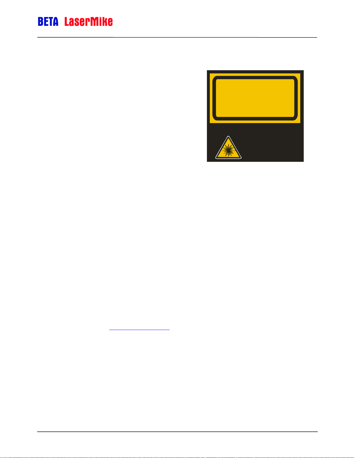
The Model LS8000-3 Non-contact Length and
Speed Gauge (Model LS8000-3) is classified as a
IIIb laser device. This category contains infrared and
visible laser devices with powers up to 500 mW.
VISIBLE AND INVISIBLE
LASER RADIATION
AVOID EXPOSURE TO BEAM
CLASS 3B LASER PRODUCT
PEAK POWER 50mW
WAVELENGTH 650-810 nm
The optical gauge in the system uses a 50 mW
Complies with EN60825-1:2001. Complies with 21 CFR 1040.10
solid-state laser device operating between 760 and
800 nm (near infrared region of the spectrum).
A class IIIb product must have the following safety
and 1040.11 except for deviations pursuant to Laser Notice
No. 50, dated J uly 26, 2001.
WARNING - NO USER SERVICEABLE
PAR TS. RE F ER SE RVI CI NG TO
QUALIFIED SERVICE PERSONNEL.
features:
A 5-second delay after power-up before laser radiation is emitted from
the gauge.
An indicator light to inform personnel near the gauge that laser
radiation is being emitted.
A mechanical device to physically block the laser beam from exiting the
gauge.
An interlock circuit to shut off the laser when the circuit is opened.
All hazards must be properly identified with warning labels.
These basic safety features are incorporated to promote safe operation of the
laser.
A class IIIb laser must also have a key switch to power the laser, ensuring that
only trained personnel can operate the instrument. Because the location of the
gauge can often make it difficult to access a key switch, the key switch needs
to be installed by the final user. It should be placed in a location that will be
readily accessible to the operators. For more information on installing the laser
key switch, see the Installing the System
section.
The user of a laser device must comply with a different set of regulations.
Many countries and individual states have passed legislation regarding the use
of laser products.
Part No. 93463 / Drawing No. 0921-01561 Page 10 of 221 Revision A (Sep 2007)
Page 11
LaserSpeed 8000-3 Instruction Handbook
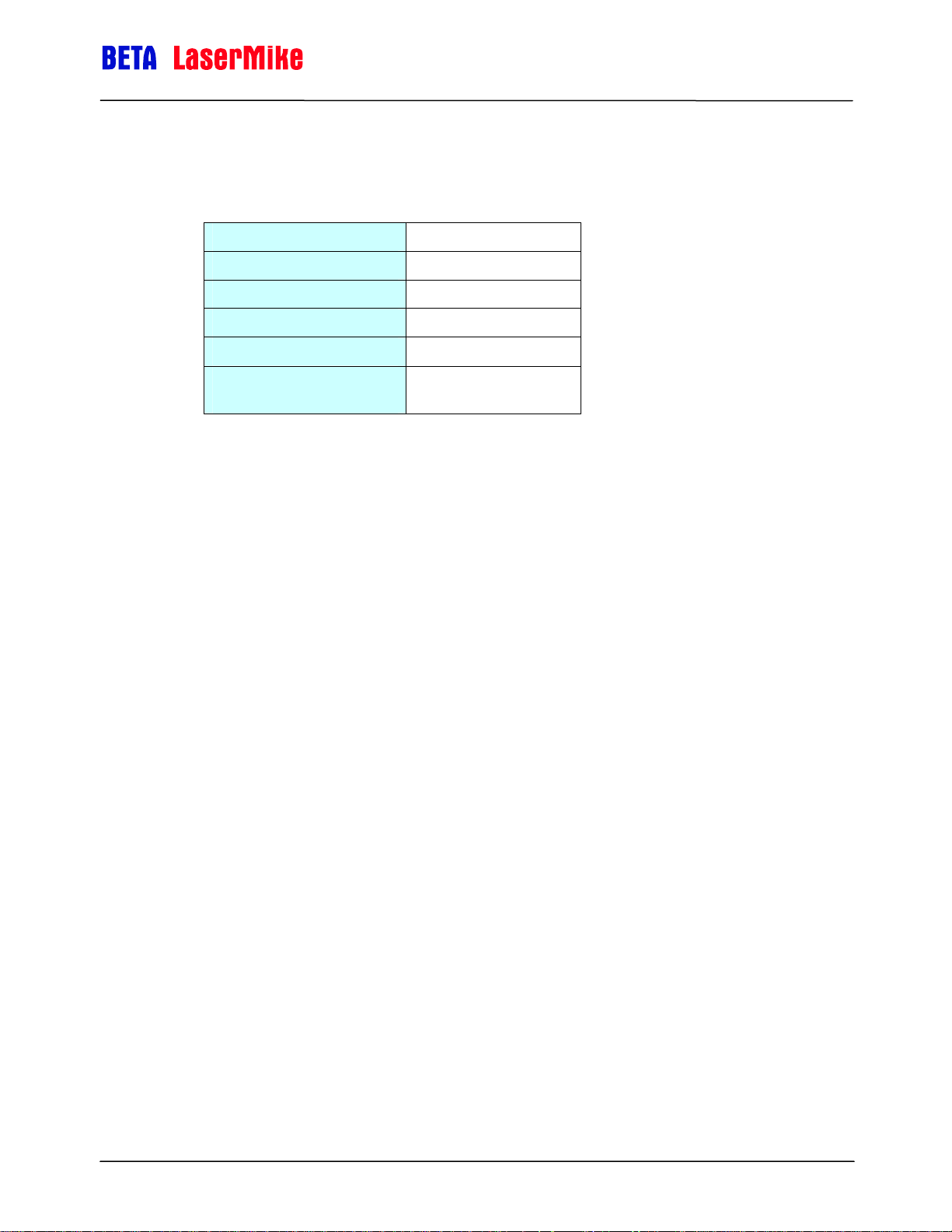
The following system specifications will help establish appropriate safety
measures.
Maximum Laser Power 0.050 watt
Laser Wavelength 0.785 micrometer
Laser Spot Size (Elliptical) 3 x 1.5 millimeters
Beam Divergence 0.5 milliradians
Pulse Rate Continuous wave
Maximum radiance (power
divided by spot-size area)
0.050 Watt/0.141372 cm
[0.3536 W/cm2]
2
Laser Safety Precautions
The laser beam in the optical gauge is very powerful and can permanently
damage eyes not protected by laser safety glasses. To avoid exposing
yourself to hazardous radiation, you must take these precautions:
Safety Information
• Never look into the laser beam. If you must look at the beam,
view it from an angle and in the direction in which the beam is
travelling.
• The beams emitted from the Model LS8000-3 are invisible to the
unaided eye. Return the beam shutter to the closed position
when the system is not in use or during setup.
• Ensure that all direct reflections are blocked.
• Remove all rings, watches, or jewellery from your hands when
working on or near the gauge—can cause hazardous reflections.
• Never install the instrument at eye level.
• Operate the system only with people who have been instructed
in laser safety.
• Post warning signs and lights that are active when laser is
operating.
Part No. 93463 / Drawing No. 0921-01561 Page 11 of 221 Revision A (Sep 2007)
Page 12
LaserSpeed 8000-3 Instruction Handbook
If your country or state has no regulations governing the safe use of lasers,
Beta LaserMike recommends that you follow the guidelines specified by the
American National Standard for the safe use of lasers (ANSI Z136.1–1986).
For a copy of this document, write to:
Laser Institute of America
13501 Ingenuity Drive, Suite 128
Orlando, Florida 32826
1-800-345-2737
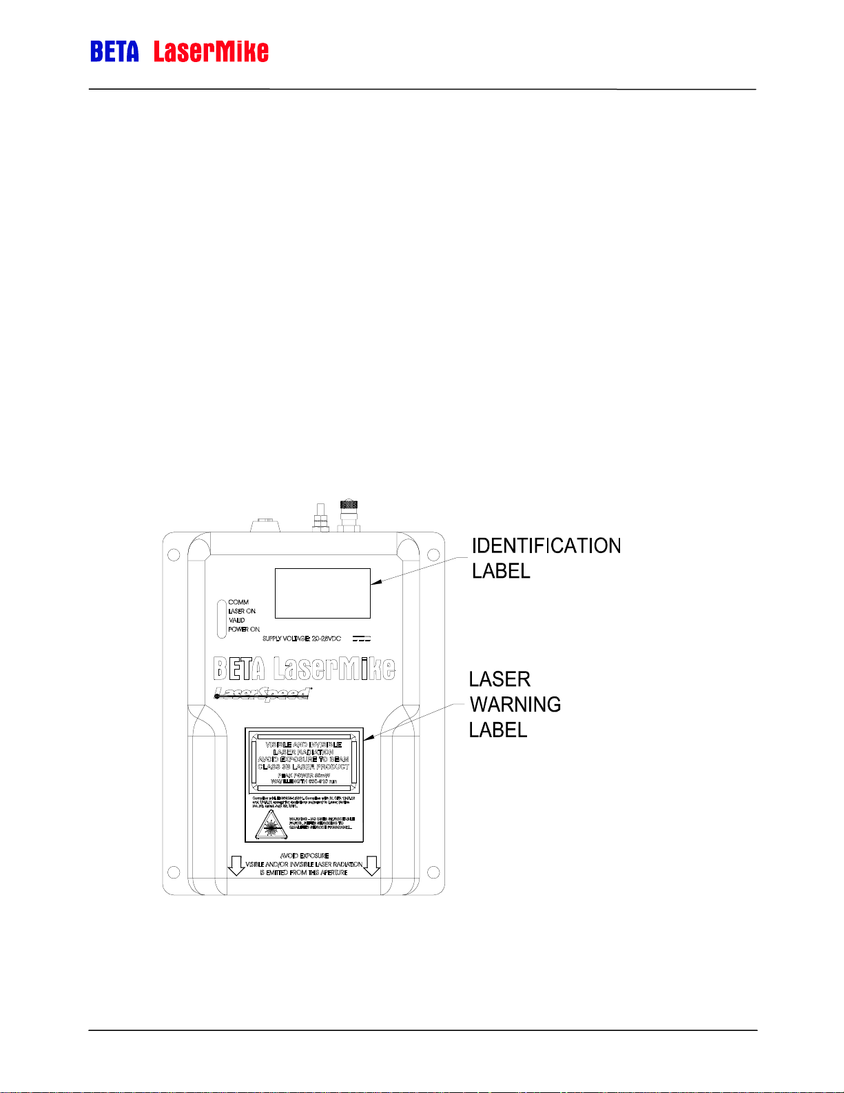
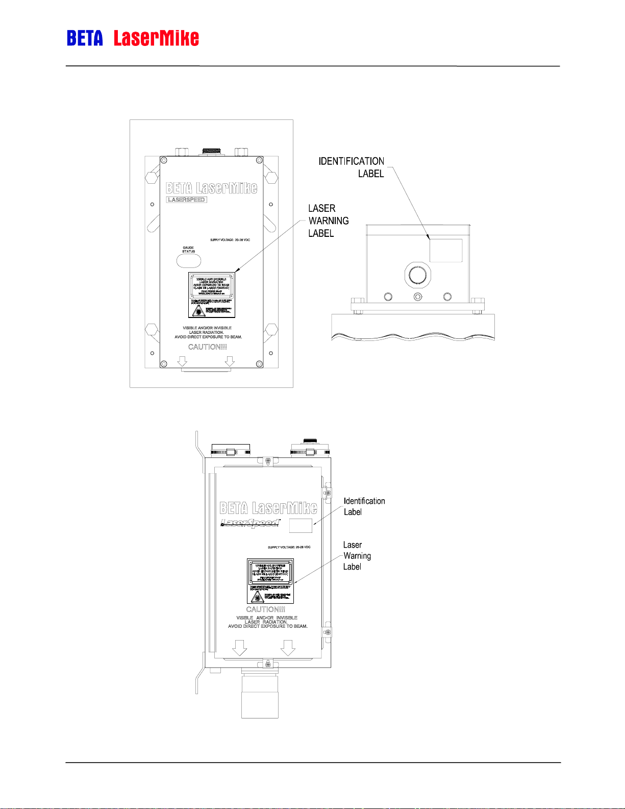
Labels and Safety Features
This section acquaints you with the advisory and identification labels on the
instrument and the safety features incorporated into the design of the
instrument. The following figures show the advisory and identification labels
on the Model LS8000-3.
Safety Information
LS8000-3 Labels
Part No. 93463 / Drawing No. 0921-01561 Page 12 of 221 Revision A (Sep 2007)
Page 13
LS8000-3E Labels
LaserSpeed 8000-3 Instruction Handbook
Safety Information
LS8000-3X Labels
Part No. 93463 / Drawing No. 0921-01561 Page 13 of 221 Revision A (Sep 2007)
Page 14

LaserSpeed 8000-3 Instruction Handbook
Introduction
This manual describes the installation and setup of the LaserSpeed 8000
gauge. For daily routine usage, see the LaserSpeed 8000 Operator Guide.
The Model LS8000-3 LaserSpeed® Non-contact Length and Speed gauge is
an industrial, Laser-Doppler based instrument that measures the velocity and
length of material. Due to the nature of the laser-based measurement, there is
no physical contact with the material. This eliminates the problems of wheel
wear and slippage that plague mechanical/encoder based length
measurement systems.
System Overview
The Model LS8000-3 is a stand-alone instrument that requires only 24 VDC
input power to operate. The system has a variety of industrial outputs. Also, a
variety of information including length, velocity, system operating parameters,
and setup parameters can be read and configured using the communications
interfaces.
Introduction
The LS8000-3 is permanently calibrated to a NIST traceable standard at the
factory. Aside from periodic cleaning of the optical window, the LS8000-3
does not require maintenance.
See the Specifications section at the end of this manual.
Principle of Operation
LaserSpeed utilizes dual-beam interferometer technology to provide accurate
velocity readings. The measured velocity is integrated over time to measure
the length of moving objects. The opto-electronic portion of the LS8000-3
generates a laser beam that is split and then crossed in space. The two
crossing beams interact, producing a fringe pattern that is orthogonal to the
plane of the two beams.
Light is scattered when material passes through the measurement region. This
scattered light is collected by the gauge and converted to electrical signals.
The frequency of the electrical signal contains information with regards to the
velocity of the material. The signal processor converts the electrical signals to
frequency information that is directly proportional to the velocity of the material
moving through the laser beams. The signal processor converts the frequency
information into velocity information and updates user outputs. In order to
determine if there is an object in the measurement area, the gauge measures
the amount of reflected laser light.
Part No. 93463 / Drawing No. 0921-01561 Page 14 of 221 Revision A (Sep 2007)
Page 15

LaserSpeed 8000-3 Instruction Handbook
g
λ
System Overview
Resultin
Electrical Signal
κ
with Frequency ( )f
t
Measurement Region
Side View
Material Surface
Material Movement
Fringe distance (d) is a function of laser wavelength
(λ) and beam angle (κ):
Period is the inverse of frequency:
Velocity is distance divided over time:
t1=
v =
Top View
d
=d
f
d
t
κ
sin2
Velocity is integrated to find Length
Part No. 93463 / Drawing No. 0921-01561 Page 15 of 221 Revision A (Sep 2007)
T
⋅=
dtvL
∫
0
Page 16

LaserSpeed 8000-3 Instruction Handbook
Installing the System
This section describes mounting, alignment and other installation concerns for
the LS8000-3.
The installation can be broken down into five steps:
Mounting the gauge
Aligning the gauge
Connecting power to the gauge
Connecting to the outputs
Maximizing gauge performance
Mounting the Gauge
Installing the System
The LS8000-3 must be placed at the correct standoff distance from the moving
material. A series of LaserSpeed gauges provide a variety of standoff
distances and depths of field.
Model Standoff Distance Depth of Field
LS8000-303 300mm (11.8 in) 35mm (1.4 in)
LS8000-306 600mm (23.6 in) 50mm (2.0 in)
LS8000-310 1000mm (39.4 in) 100mm (3.9 in)
LS8000-315 1500mm (59.0 in) 200mm (7.9 in)
LS8000-320 2000mm (78.7 in) 200mm (7.9 in)
LS8000-325 2500mm (98.4 in) 200mm (7.9 in)
Please refer to the following Appendices for mounting dimensions and
installation drawings:
Model Section
LS8000 Appendix A
LS8000E Appendix B
LS8000X Appendix C
Part No. 93463 / Drawing No. 0921-01561 Page 16 of 221 Revision A (Sep 2007)
Page 17

LaserSpeed 8000-3 Instruction Handbook
Mounting Distance
When the material is within the depth of field, the gauge makes accurate
measurements. Since the best signal comes from the center of the depth of
field, the center is the source of the best measurements. This is because the
two laser beams totally overlap at the center of the beam crossings and all of
the laser power is used to form fringes.
At the edges of the depth of field, however, some beam-crossing areas
overlap and some do not. The areas that overlap form fringes and thus yield
useful Doppler signals; the areas that do not overlap do not form fringes;
rather, they produce only noise with no Doppler signals. Any measurements
made outside the depth of field may not be reliable.
Laser Safety
When mounting of the gauge, ensure that the laser beams are blocked by
machinery or beam blocks when material is not present in the measurement
area.
Installing the System
Environmental Conditions
Ambient Temperature
All LaserSpeed gauges have a built-in cooling system for applications in which
ambient temperatures exceed 45ºC.
Cooling fluids can be routed through the gauge using the 1/8-inch NPT fittings
(1/4" NPT on LS8000E and LS8000X) on the back of the gauge. Typical flow
rates of 1.5 litres/minute for water and 50 liters/minute for air are sufficient.
There is minimal pressure drop through the gauge, so supply pressure can be
very low.
Ensure that the water temperature is above the condensation temperature or
dew point, to prevent condensation from collecting on the front window of the
gauge. If water condenses on the optical window, the laser beams could be
blocked, resulting in reduced performance or loss of function.
Coolant
In applications with coolants on the material, an air jet may be required to
remove the coolant from the measurement area. Since the speed of the
coolant is generally different from that of the material, erroneous
measurements could result. When incorporating an air jet, be sure to blow the
coolant from the measurement volume at 90° from the material’s motion. If the
Part No. 93463 / Drawing No. 0921-01561 Page 17 of 221 Revision A (Sep 2007)
Page 18
LaserSpeed 8000-3 Instruction Handbook
coolant is blown off in the same direction the material is moving, the air
velocity can add or subtract from the material’s velocity; this too may cause
erroneous measurements.
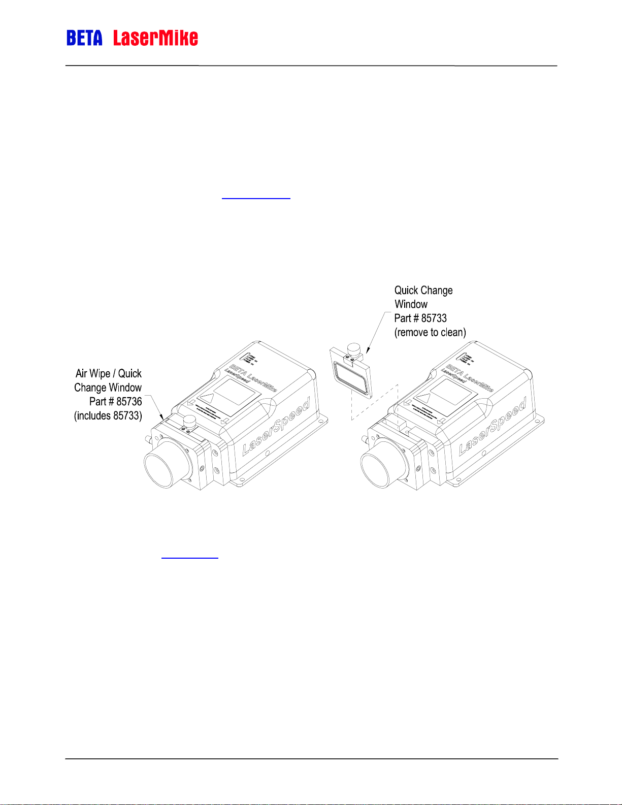
Air Wipe / Quick Change Window
To prevent dust, dirt, and moisture from accumulating on the optical window
the gauge can be fitted with an Air Wipe/Quick Change Window. Clean,
instrument grade air (see Specifications
pressure over the window to keep it clean. The window can be removed for
easy cleaning. A clean, soft cloth should be used to clean the window. If an
abrasive cloth is used, the optical coating may be damaged, leading to poor
measurements. When replacing the window, put a small amount of vacuum
grease on the O-Ring.
section for details) is blown at low
Installing the System
For measurements and details about removing the Air Wipe/Quick Change
Window, see Appendix A
.
Steam & Mist
Steam or mist is sometimes present in some applications. The air-wipe is not
designed to clear steam or mist between the gauge and material, but only to
keep contaminants from depositing on the optics window. Another means of
removing steam or mist may need to be used. The steam or mist may be light
enough to allow the laser beams to pass through without interference. If this is
not true, a fan may be used to clear out the steam or mist between the gauge
and housing. If a fan is not adequate or practical, an “air purge” can be
installed to clear the beam path. Contact your Beta LaserMike representative
Part No. 93463 / Drawing No. 0921-01561 Page 18 of 221 Revision A (Sep 2007)
Page 19
LaserSpeed 8000-3 Instruction Handbook
for more details. When mounting the gauge, be aware of the environment in
which the gauge is operating. Steam, mist, coolant on the material, ambient
temperature, scale and slag may all affect the performance of the gauge.
These environmental conditions may need to be modified as mentioned above
in order to maximize the performance of the gauge.
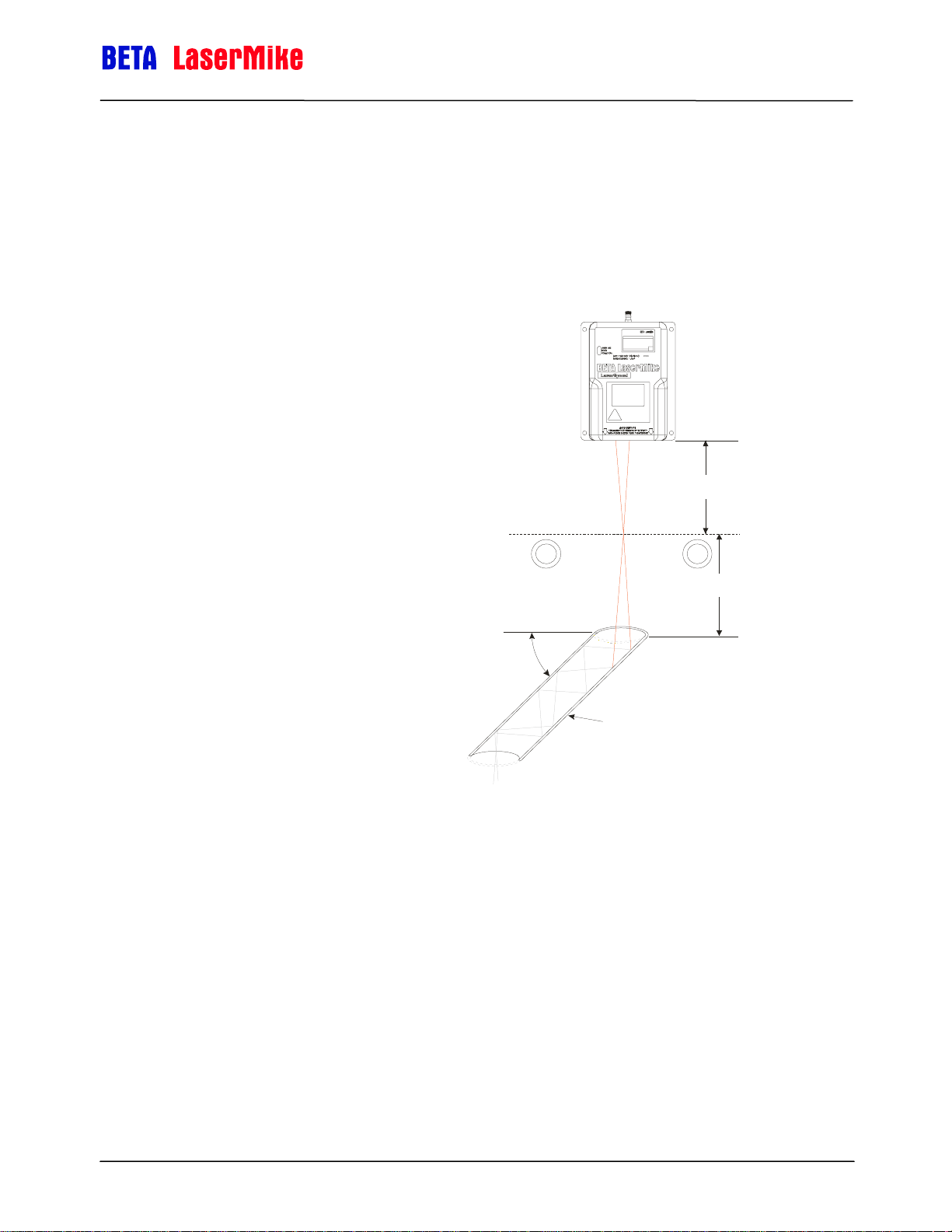
Mounting Location
When mounting the gauge over the
material, be sure the gauge is not
directly over a roller or some other
device. If the laser beam from the gauge
strikes an object, it may detect a false
Material Present. In this case, the gauge
will not be able to detect when the
actual material is not in the
measurement volume.
Installing the System
Standoff
Distance
A device that captures most of the laser
light is called a beam dump and may be
required (see figure). A suitable beam
Standoff
Distance
dump is a large-diameter pipe, 150
millimeters (6 inches) or larger, angled
at 45° from the laser beams. A rusty
Cut at 45
º
pipe is an excellent beam dump. If scale
can deposit in the base of the beam
dump, the pipe may need to be cleaned
periodically to prevent false Material
Beam Dump
Open Both Ends
Present readings. The beam dump
should be far enough from the gauge
that it cannot be measured. A good guideline is to place the beam dump at
least double the standoff distance from the gauge.
PAS SL INE
Rollers
Part No. 93463 / Drawing No. 0921-01561 Page 19 of 221 Revision A (Sep 2007)
Page 20
LaserSpeed 8000-3 Instruction Handbook
t
r
p
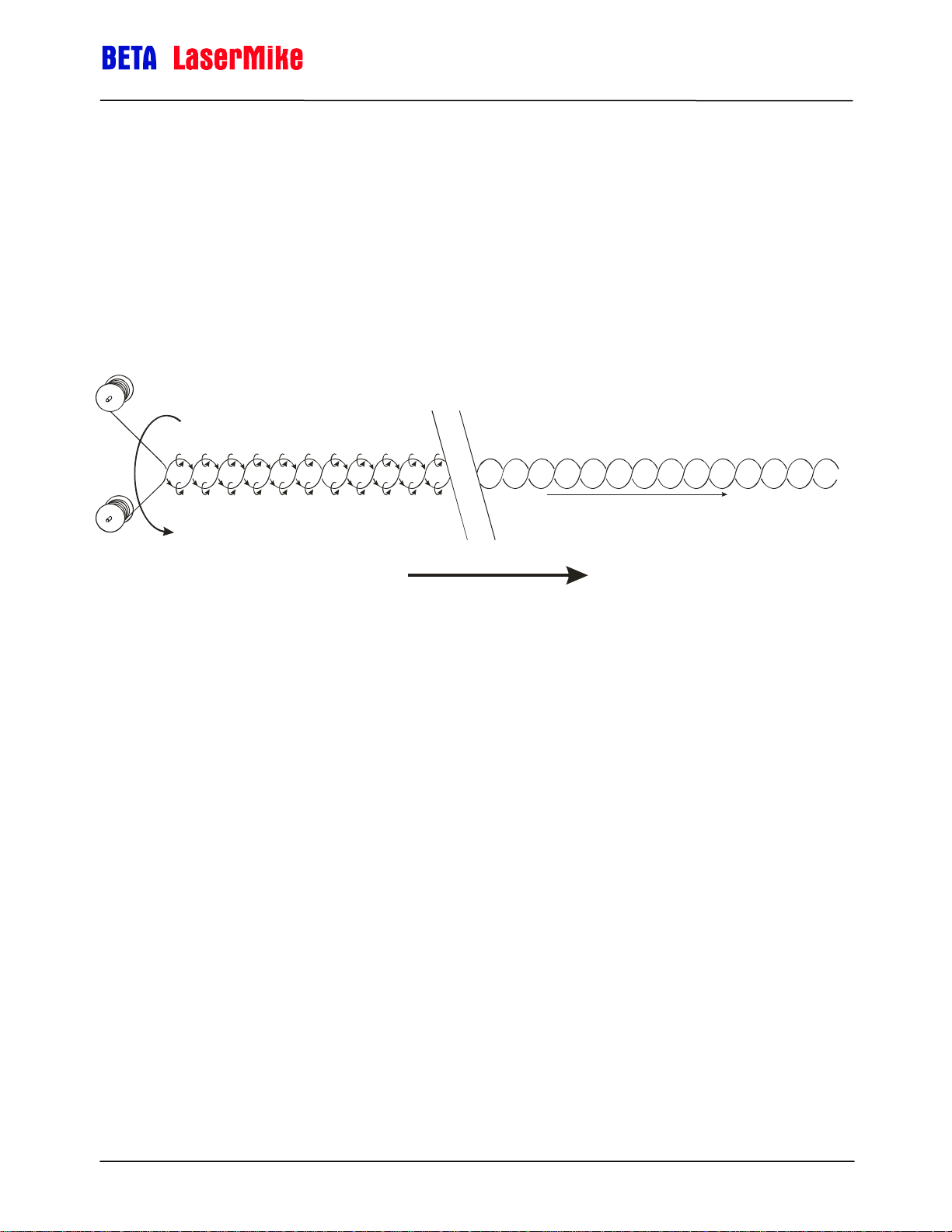
Twinner Lines
When mounting the gauge on a twinner line, the gauge should be positioned
far enough from the twinner that the twist is set. If the gauge is placed close to
the twinner, it may not be able to measure due to excessive vibration and the
spin imparted on the wire due to the twisting motion. Moving the gauge down
the line farther from the twinner may improve the gauge's ability to make
measurements.
Installing the System
Near Twinne
Wires spin and
corkscrew (make it
look like wires are
not moving)
Near Takeu
Twist is set, wires not
spinning or corkscrewing.
Line Movemen
Part No. 93463 / Drawing No. 0921-01561 Page 20 of 221 Revision A (Sep 2007)
Page 21

LaserSpeed 8000-3 Instruction Handbook
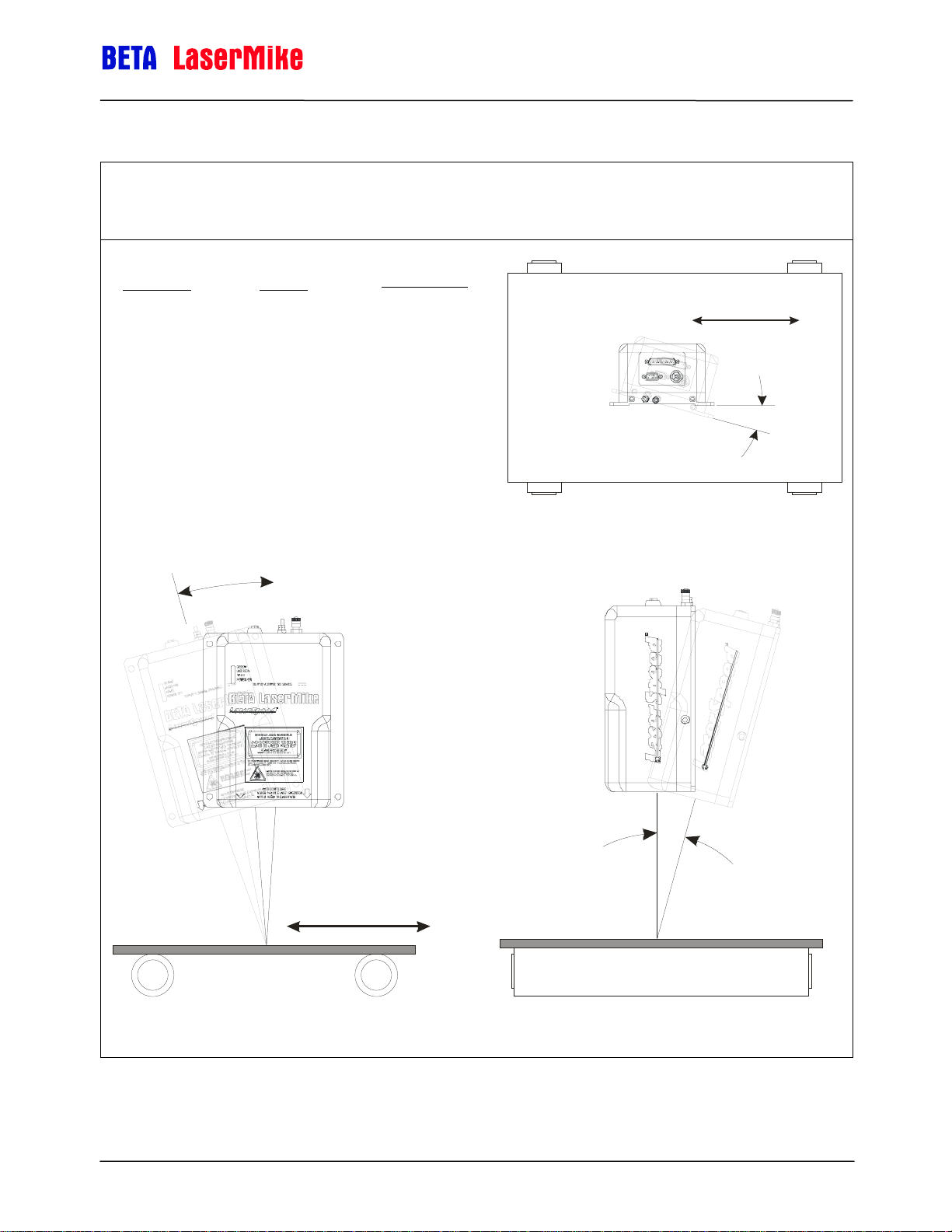
Aligning the Gauge
Once the gauge is mounted at the proper standoff distance, the critical
alignment angles need to be checked. To obtain accurate results, the LS80003 must be mounted so the surface being measured is perpendicular to the
optical axis. The best method to ensure this is to place a level alongside the
gauge. The material being measured should be parallel to the front face of the
gauge and the material motion should be parallel to the base of the gauge.
The velocity measurement, which is made in the plane of the two laser beams,
is the rate at which the material passes the fringes of the beams. When the
motion of the material is perpendicular to the fringes, the velocity
measurement is considered calibrated. If the fringes are at an angle to the
motion of the material (angular rotation), measurement errors occur. The
measured velocity equals the actual velocity multiplied by the cosine of the
angle by which the alignment deviates from the direction of material
movement.
Installing the System
Three types of misalignment are possible. Two of the three are responsible for
measurement errors: rotation about the optical axis and tilt in the plane of the
beams. The errors are proportional to the sine of the misalignment angle.
Misalignment will always make the gauge measure velocities and lengths that
are too low.
Part No. 93463 / Drawing No. 0921-01561 Page 21 of 221 Revision A (Sep 2007)
Page 22
LaserSpeed 8000-3 Instruction Handbook
r
r
Installing the System
Types of Gauge Misalignment
Measured Velocity = Actual Velocity x cos(A) x cos(B)
Error Angle
(Degrees)
0
0.25
0.50
0.75
1.0
2.0
3.0
4.0
5.0
10
Cosine
1
0.99999
0.99996
0.99991
0.99985
0.99939
0.99863
0.99756
0.99619
0.98481
Speed and
Length Error
(%)
0
-0.001
-0.004
-0.009
-0.015
-0.061
-0.137
-0.244
-0.381
-1.519
Material Movement
A
Rotat ion About Optical Axis
- Causes Measurement Erro
B
C
Material Movement
Not perpendicular to Material Motion
- Causes Measurement Error
Part No. 93463 / Drawing No. 0921-01561 Page 22 of 221 Revision A (Sep 2007)
Material Movement
into/out of page
Not perpendicular to material edges
- No measurement erro
Page 23
LaserSpeed 8000-3 Instruction Handbook
G
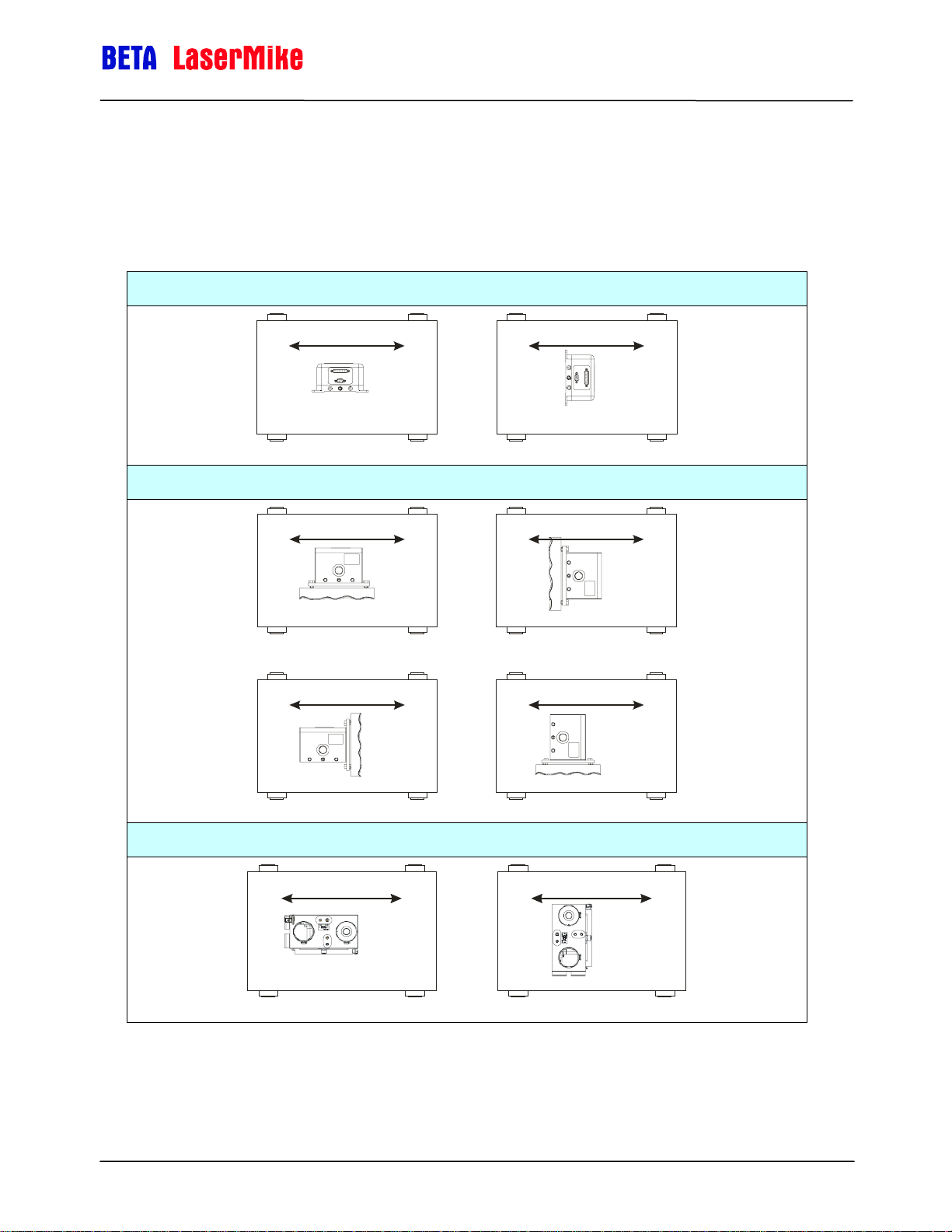
Gauge Orientation
The LaserSpeed gauge must be mounted such that the material to be
measured moves in a direction parallel to the bottom of the LS8000-3, as
shown below.
LS8000-3
Installing the System
Material Movement
☺
Material Movement
3
RIGHT WRONG
LS8000-3E – can be mounted either from the bottom or the side
Material Movement
☺
3
RIGHT WRONG
Material Movement
☺
3
RIGHT
LS8000-3X
Material Movement
Material Movement
WRON
2
2
2
Material Movement
☺
Material Movement
3
RIGHT
Part No. 93463 / Drawing No. 0921-01561 Page 23 of 221 Revision A (Sep 2007)
2
WRONG
Page 24
LaserSpeed 8000-3 Instruction Handbook
Connecting Power to the Gauge
The gauge requires a 20–28 VDC (nominal 24 VDC) supply to be connected to
Pin 24 and/or Pin 25 with the corresponding ground to Pin 12 and/or Pin 13 of
the 25-pin D-sub connector. The supply should be able to drive at least 2
Amps. For detailed information on supplying power to the gauge, see
Appendix D
Notes: Do not attach wires to the gauge while power is applied. Make all
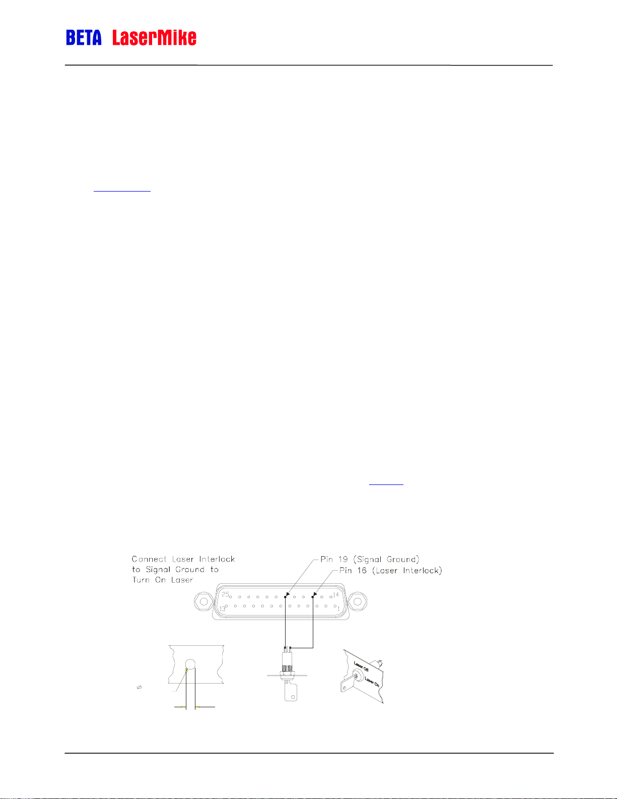
The LS8000-3 is classified as a kit, according to CDRH regulations. It is your
responsibility to install a key switch to control the operation of the device. The
key switch should be installed as shown in the following figure. It is in line with
the 24-volt supply line that will service to power the device. The recommended
key switch can be found in the accessory kit. The key switch should be
mounted in a convenient location that does not require exposure to the laser
beams. After installation, label the panel as to which position corresponds to
“Laser On” and “Laser Off.”
.
wiring connections with power turned off. The gauge contains internal
fusing (3A, 125 V) on the 24 VDC supply line. This fuse is not user
serviceable.
Installing the System
The following figure shows the correct installation of the recommended switch
(C&K Components part number YM06132C205NQ). If another type of key
switch is used, it should be verified that the key is removable only in the “Laser
Off” position.
For more information on laser safety issues, refer to the Safety
section at the
beginning of this manual.
Warning: A key switch must be installed and labelled correctly to ensure
proper protection of personnel working with the laser.
Panel Cutout
for Keyswitch
Laser Off
Lase r On
0.50in
[12.7mm]
0.42in
[10.7mm]
Part No. 93463 / Drawing No. 0921-01561 Page 24 of 221 Revision A (Sep 2007)
Page 25
LaserSpeed 8000-3 Instruction Handbook
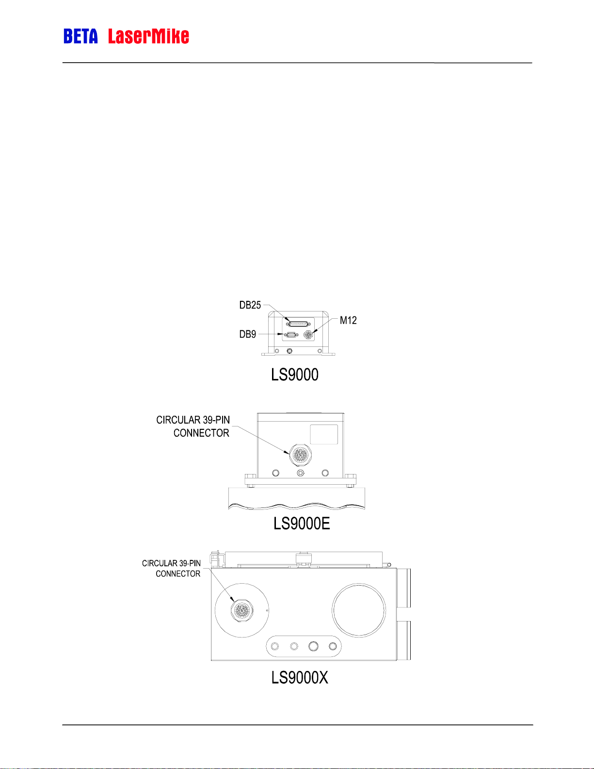
Connecting to Outputs
On the LS8000-3 model, the outputs of the gauge are contained on the 9-pin
and 25-pin D-sub connectors, and the M12 D-Coded Ethernet connector. On
the LS8000-3E and LS8000-3X, all outputs are contained on a 39-pin circular
connector. Their pin values are shown in the following tables. Each signal is
explained in detail in the Interfacing with the LS8000-3 section.
Note: In order for the LS8000-3 to be operational, pins 16 and 17 must
be connected to signal ground. These signals operate the internal
laser shutter and the laser interlock. When these connections are
open, the laser will not turn on and the shutter will not open. You
must provide the correct signals to operate the gauge.
Installing the System
Part No. 93463 / Drawing No. 0921-01561 Page 25 of 221 Revision A (Sep 2007)
Page 26
LS8000-3 25-Pin Connector Pinout
Pin Description
1 RS-232 Transmit (from LS8000-3 to host)
2 RS-232 Receive (from host to LS8000-3)
3 Phase A True – High Speed Output (RS-422 Drivers)
4 Phase A False – User Scaleable (5-24V Output)
5 Phase A False – High Speed Output (RS-422 Drivers)
6 Phase B True – User Scaleable (5-24V Output)
7 Phase B True – High Speed Output (RS-422 Drivers)
LaserSpeed 8000-3 Instruction Handbook
Installing the System
8 Phase B False – User Scaleable (5-24V Output)
9 Phase B False – High Speed Output (RS-422 Drivers)
10 Material Present Input (5-24V Input)
11 Signal Ground for Inputs/Outputs/Serial
12 Power Ground for 24V Input
13 Power Ground for 24V Input
14 Measurement Direction Input (5-24V Input)
15 Phase A True – User Scaleable (5-24V Output)
16 Laser Interlock (Connect to Signal Ground to Turn On Laser)
17 Shutter Control (Connect to Signal Ground to Open Shutter)
18 Length Reset Input (5-24V Input)
19 Signal Ground for Inputs/Outputs/Serial
20 User VIN – Voltage input for Isolated Pulse Outputs (5 to 28V DC). The
voltage supplied will be the voltage level of the pulse outputs supplied by
the LS8000-3. If a Voltage is not supplied, the pulse outputs will be
approximately 4.5V.
21 Signal Ground for Inputs/Outputs/Serial
22 Index Pulse True - User Scaleable (5-24V Output)
23 Index Pulse False - User Scaleable (5-24V Output)
24 24V Fused Input
25 24V Fused Input
Part No. 93463 / Drawing No. 0921-01561 Page 26 of 221 Revision A (Sep 2007)
Page 27
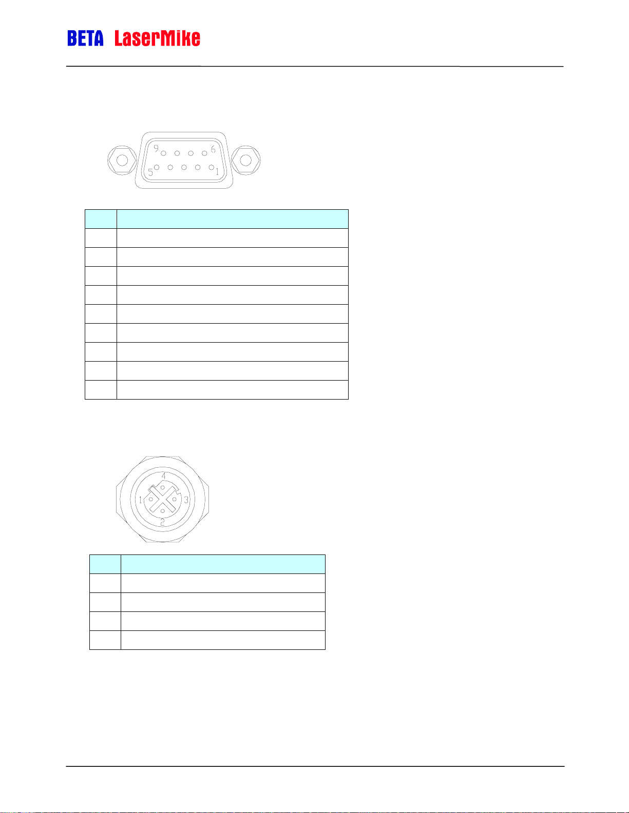
LS8000-3 9-Pin Connector Pinout
Pin Description
1 RS-422 Transmit + (from LS8000-3 to host)
2 RS-422 Transmit – (from LS8000-3 to host)
3 RS-422 Receive + (from host to LS8000-3)
4 RS-422 Receive – (from host to LS8000-3)
5 Signal Ground for Inputs/Outputs/Serial
6 Analog Output Voltage
LaserSpeed 8000-3 Instruction Handbook
Installing the System
7 Analog Output Ground
8 Measurement Synchronization Input +
9 Measurement Synchronization Input -
LS8000-3 M12 Connector Pinout
Pin Description
1 Ethernet TX+ (from LS8000-3 to host/switch)
2 Ethernet RX+ (from host/switch to LS8000-3)
3 Ethernet TX- (from LS8000-3 to host/switch)
4 Ethernet RX- (from host/switch to LS8000-3)
Part No. 93463 / Drawing No. 0921-01561 Page 27 of 221 Revision A (Sep 2007)
Page 28
LaserSpeed 8000-3 Instruction Handbook
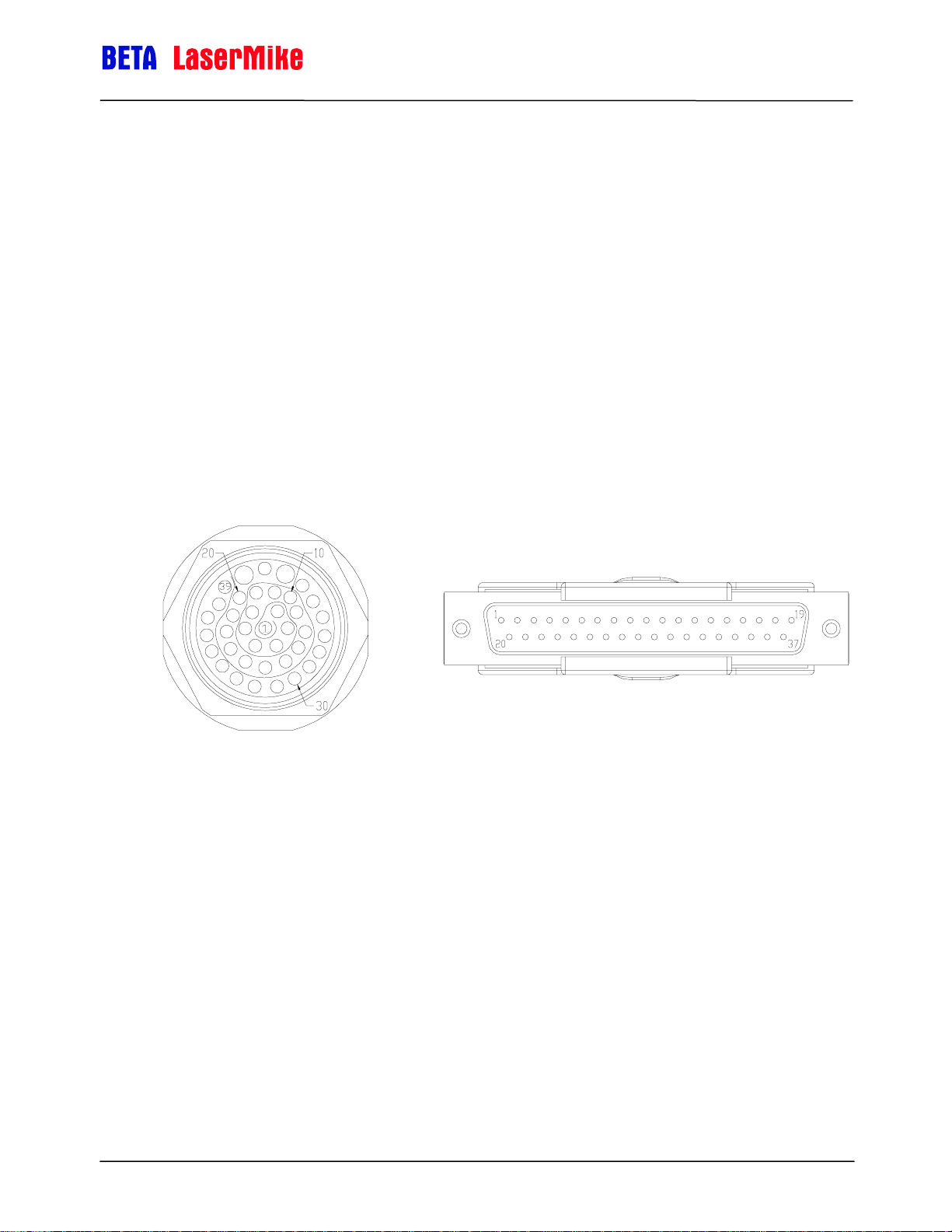
LS8000-3E/LS8000-3X Connector Pinout
The LS8000-3E/LS8000-3X cables have a circular 39-pin military connector on
the gauge end and a DB37 connector on the opposite end. The pinouts of
both connectors are listed below. Pins 21 and 23 of the circular connector are
not internally connected. The 39-pin military connector is internally connected
to the LS8000-3 DB25, DB9, and M12 connectors. These connections are
listed in the following table.
Installing the System
LS8000-3E/X Circular Connector DB37 Cable Connector Pin Locations
Part No. 93463 / Drawing No. 0921-01561 Page 28 of 221 Revision A (Sep 2007)
Page 29

LaserSpeed 8000-3 Instruction Handbook
Installing the System
LS8000-3 Connector Pin DB37 39-Pin Description
1 1 1 RS232 Transmit (from LS8000-3 to host)
2 2 2 RS232 Receive (from host to LS8000-3)
3 3 3 Phase A True – High Speed Output (RS-422 Drivers)
4 4 4 Phase A False – User Scaleable (5-24V Output)
5 5 5 Phase A False – High Speed Output (RS-422 Drivers)
6 6 6 Phase B True – User Scaleable (5-24V Output)
7 7 7 Phase B True – High Speed Output (RS-422 Drivers)
8 8 8 Phase B False – User Scaleable (5-24V Output)
9 9 9 Phase B False – High Speed Output (RS-422 Drivers)
10 10 10 Material Present Input (5-24V Input)
11 11 11 Signal Ground for Inputs/Outputs/Serial
12 12 12 Power Ground for 24V Input
13 13 13 Power Ground for 24V Input
DB25
DB9
M12
14 14 14 Measurement Direction Input (5-24V Input)
15 15 15 Phase A True – User Scaleable (5-24V Output)
16 16 16 Laser Interlock (Connect to Signal Ground to Turn On Laser)
17 17 17 Shutter Control (Connect to Signal Ground to Open Shutter)
18 18 18 Length Reset Input (5-24V Input)
19 19 19 Signal Ground for Inputs/Outputs/Serial
User VIN – Voltage input for Isolated Pulse Outputs (5 to 28V
20 20 20
21 21 22 Signal Ground for Inputs/Outputs/Serial
22 22 24 Index Pulse True - User Scaleable (5-24V Output)
23 23 25 Index Pulse False - User Scaleable (5-24V Output)
24 24 26 24V Fused Input
25 25 27 24V Fused Input
1 26 28 RS422 Transmit + (from LS8000-3 to host)
2 27 29 RS422 Transmit – (from LS8000-3 to host)
3 28 30 RS422 Receive + (from host to LS8000-3)
4 29 31 RS422 Receive – (from host to LS8000-3)
6 30 32 Analog Output Voltage
7 31 33 Analog Output Ground
8 32 34 Measurement Synchronization Input +
9 33 35 Measurement Synchronization Input -
1 34 36 Ethernet TX+
2 35 37 Ethernet RX+
3 36 38 Ethernet TX-
4 37 39 Ethernet RX-
DC). The voltage supplied will be the voltage level of the pulse
outputs supplied by the LS8000-3. If a Voltage is not supplied,
the pulse outputs will be approximately 4.5V.
Part No. 93463 / Drawing No. 0921-01561 Page 29 of 221 Revision A (Sep 2007)
Page 30

LaserSpeed 8000-3 Instruction Handbook
LS8000-3E/LS8000-3X Breakaway Cable Pinout
LaserSpeed breakaway cables have 39-pin military connectors on both ends
(male on one end and female on the other) and have pinouts identical to the
standard gauge cable.
Installing the System
39-Pin Male
1 1 RS232 Transmit (from LS8000-3 to host)
2 2 RS232 Receive (from host to LS8000-3)
3 3 Phase A True – High Speed Output (RS-422 Drivers)
4 4 Phase A False – User Scaleable (5-24V Output)
5 5 Phase A False – High Speed Output (RS-422 Drivers)
6 6 Phase B True – User Scaleable (5-24V Output)
7 7 Phase B True – High Speed Output (RS-422 Drivers)
8 8 Phase B False – User Scaleable (5-24V Output)
9 9 Phase B False – High Speed Output (RS-422 Drivers)
10 10 Material Present Input (5-24V Input)
11 11 Signal Ground for Inputs/Outputs/Serial
12 12 Power Ground for 24V Input
13 13 Power Ground for 24V Input
14 14 Measurement Direction Input (5-24V Input)
15 15 Phase A True – User Scaleable (5-24V Output)
16 16 Laser Interlock (Connect to Signal Ground to Turn On Laser)
17 17 Shutter Control (Connect to Signal Ground to Open Shutter)
18 18 Length Reset Input (5-24V Input)
19 19 Signal Ground for Inputs/Outputs/Serial
20 20
22 22 Signal Ground for Inputs/Outputs/Serial
24 24 Index Pulse True - User Scaleable (5-24V Output)
25 25 Index Pulse False - User Scaleable (5-24V Output)
26 26 24V Fused Input
27 27 24V Fused Input
28 28 RS422 Transmit + (from LS8000-3 to host)
29 29 RS422 Transmit – (from LS8000-3 to host)
30 30 RS422 Receive + (from host to LS8000-3)
31 31 RS422 Receive – (from host to LS8000-3)
32 32 Analog Output Voltage
33 33 Analog Output Ground
34 34 Measurement Synchronization Input +
35 35 Measurement Synchronization Input 36 36 Ethernet TX+
37 37 Ethernet RX+
38 38 Ethernet TX39 39 Ethernet RX-
39-Pin
Female
Description
User VIN – Voltage input for Isolated Pulse Outputs (5 to 28V DC). The
voltage supplied will be the voltage level of the pulse outputs supplied by the
LS8000-3. If a Voltage is not supplied, the pulse outputs will be
approximately 4.5V.
Part No. 93463 / Drawing No. 0921-01561 Page 30 of 221 Revision A (Sep 2007)
Page 31

LaserSpeed 8000-3 Instruction Handbook
Maximizing Performance
The system is now at the point where it can be powered on and the laser
activated so beams are emitted from the front of the gauge. Be sure that the
laser interlock and shutter control circuits are functioning properly.
When Pin 16 is connected to GND (Pin 11, 19, or 21), the laser
becomes operational.
When Pin 17 is connected to GND (Pin 11, 19, or 21), the shutter will
open.
Check the key switch to verify the laser power can be controlled.
Warning: Avoid exposure to the beam. Never look directly into the laser
beams, even when wearing protective eyewear. Eye damage
could result.
Installing the System
Note: There may be some delay time between when the system is powered
on, and when the laser comes on. There is a 7 second delay after
power is applied to the laser (key switch on, laser interlock closed)
before the laser turns on. The laser will also not turn on until the
laser temperature controller stabilizes. This may take a few minutes
after power is initially applied. The standoff distance can be verified
by using a business card or sheet of white paper. Both beams can
be viewed and the area where the beams overlap is the active
measurement region. The location where the overlap of the beams is
smallest is the center of the measurement region. This location
corresponds to the standoff distance and is where the beams should
intersect the product.
The configuration and setup of the gauge can be verified and/or changed
using the supplied LaserTrak Software or directly using the serial commands
listed in the Communication Protocol
approaches requires a computer with an RS-232 serial port connected to pins
1 and 2 of the 25-pin D-sub connector, or an RS-422 serial port connected to
pins 1-4 of the 9-pin D-sub connector.
Once proper communication is established (see the See the LaserTrak
Software section for help), it is recommended to check the Quality Factor (QF).
QF can be checked using LaserTrak, and viewing the chart recorder screen. If
it is below 15, try to move the product or the gauge slightly (adjust the
standoff) and look for improvements in QF. Once QF is maximized, change
the line speed and look for a corresponding velocity change on the chart
recorder.
section. Utilizing either one of these
Part No. 93463 / Drawing No. 0921-01561 Page 31 of 221 Revision A (Sep 2007)
Page 32

LaserSpeed 8000-3 Instruction Handbook
Alternatively, the analog port can be configured to output QF on a 0–1 V scale.
The QF can then be monitored by connecting a panel meter to the analog
output and displaying the voltage. A third method of monitoring the Quality
Factor is to reassign one of the pulse outputs to output the Quality Factor as a
frequency output.
To ensure quality measurements, the laser beams must maintain “contact”
with the product. If the product exhibits large movements during operation, it
should be stabilized with external roller guides. Beta LaserMike offers optional
product guides. Contact your local Beta LaserMike sales representative or the
factory for additional information.
Material Present Adjustment
The intensity of the light reflected from the measurement area can be used to
determine whether material is in the measurement zone or not. To
compensate for varying reflectivity of different materials, it is often necessary
to adjust the threshold of the light detection circuit. This adjustment can be
made with a serial command or by using the LaserTrak software.
Installing the System
Material Present Dropout Time Selection
If you are taking measurements and the Material Present signal is lost for less
than the selected Material Present dropout time, the loss is considered to be a
momentary loss of signal and is ignored. If the signal is lost for longer than the
selected Material Present dropout time, it is considered the end of the material.
This function is very useful when making length measurements on poor
reflecting material.
Validation Time Limit Selection
The validation time limit is used to start making length calculations. Two
conditions are necessary to start a length measurement: Material Present and
valid velocity data. When material enters the measurement volume, the
system determines the time between the Material Present signal and the first
valid data. If the time is less than or equal to the validation time limit
(selectable via LaserTrak or ‘G’ command), then the start-up length-correction
is calculated and a length measurement is initialized. If the time between the
Material Present signal and the first valid velocity data is longer than the
validation limit, then the length calculation is aborted and an error or fault is
sent. This error is sent by setting the length output (either in continuous output
mode or Final Length Mode) to all 9’s.
Part No. 93463 / Drawing No. 0921-01561 Page 32 of 221 Revision A (Sep 2007)
Page 33

LaserSpeed 8000-3 Instruction Handbook
Starting/Ending Length Correction
The Validation Time Limit feature is used because the Material Present signal
tells the gauge that material is indeed moving through the measurement zone.
If valid velocity measurements cannot be made, then a small amount of length
will not be accumulated which, in turn, will cause a length error. This may or
may not be a problem, depending on the velocity of the material when it
passes through the measurement volume during this time. The start-up
length-correction is executed to obtain a more accurate length reading. Each
measurement update is divided into small subintervals. When the Material
Present signal is received within an update period, the time it was received is
recorded with a subinterval clock. The length is calculated by using valid
velocity and integrating over the time measured with the subinterval clock. For
example, if the material speed is 10 meters per minute and material enters the
measurement volume in the middle of the 1-millisecond update period, the
subinterval time of 0.5ms is used to calculate length rather than the 1millisecond period. In this case, a 0.083 mm correction would be made. The
same type of correction is made when the material leaves the measurement
volume.
Installing the System
If problems are encountered during any of the installation steps, contact Beta
LaserMike for assistance.
Part No. 93463 / Drawing No. 0921-01561 Page 33 of 221 Revision A (Sep 2007)
Page 34

LaserSpeed 8000-3 Instruction Handbook
Interfacing with the LS8000-3
Interfacing with the LS8000-3
The LS8000-3 has a variety of outputs that allow length and velocity data to be
transmitted to external devices or control algorithms. All of these signals are
located on the connector(s) on the back of the instrument.
LS8000-3 Interface Connectors
The LS8000-3 has three interface connectors:
Connector Gender Signals
DB25 Male
DB9 Male
M12 Female D-Coded Ethernet
Quad Pulses, RS-232, Interlocks,
Power
RS-422, Analog, Measurement
Synchronization
LS8000-3 Rear Panel Connectors
Part No. 93463 / Drawing No. 0921-01561 Page 34 of 221 Revision A (Sep 2007)
Page 35

LaserSpeed 8000-3 Instruction Handbook
Interfacing with the LS8000-3
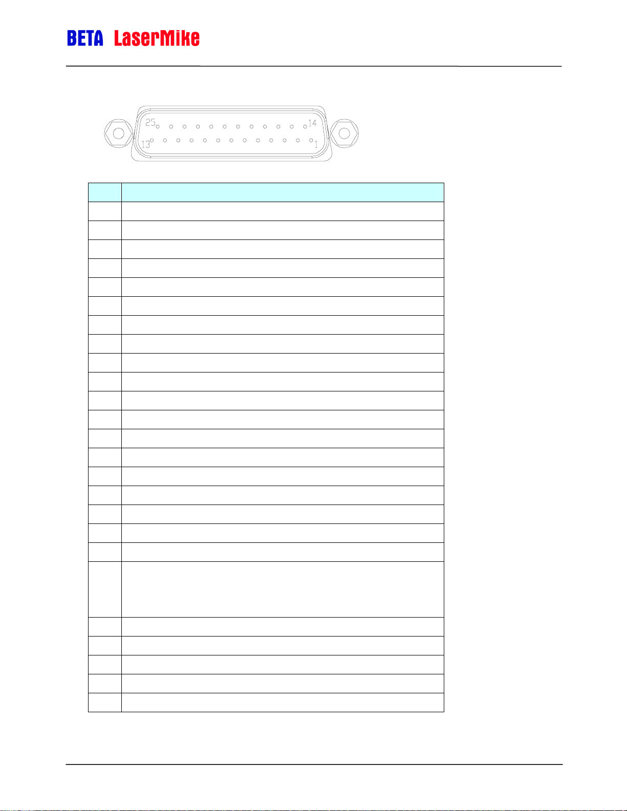
DB25 Connector
The 25-pin interface port contains pins which deliver the quadrature pulse
outputs, RS-232 serial communications, safety interlock signals, and the 24 V
supply required to power the gauge. Several inputs are available for operation
of the instrument. The connector is a standard 25-Pin male D-Sub connector.
The connector is shown below looking at the gauge's rear panel with the
gauge base plate down.
Pin Description
1 RS232 Transmit (from LS8000-3 to host)
2 RS232 Receive (from host to LS8000-3)
3 Phase A True – High Speed Output (RS-422 Drivers)
4 Phase A False – User Scaleable (5-24V Output)
5 Phase A False – High Speed Output (RS-422 Drivers)
6 Phase B True – User Scaleable (5-24V Output)
7 Phase B True – High Speed Output (RS-422 Drivers)
8 Phase B False – User Scaleable (5-24V Output)
9 Phase B False – High Speed Output (RS-422 Drivers)
10 Material Present Input (5-24V Input)
11 Signal Ground for Inputs/Outputs/Serial
12 Power Ground for 24V Input
13 Power Ground for 24V Input
14 Measurement Direction Input (5-24V Input)
15 Phase A True – User Scaleable (5-24V Output)
16 Laser Interlock (Connect to Signal Ground to Turn On Laser)
17 Shutter Control (Connect to Signal Ground to Open Shutter)
18 Length Reset Input (5-24V Input)
19 Signal Ground for Inputs/Outputs/Serial
20 User VIN – Voltage input for Isolated Pulse Outputs (5 to 28V DC). The voltage
supplied will be the voltage level of the pulse outputs supplied by the LS8000-3.
If a Voltage is not supplied, the pulse outputs will be approximately 4.5V.
21 Signal Ground for Inputs/Outputs/Serial
22 Index Pulse True - User Scaleable (5-24V Output)
23 Index Pulse False - User Scaleable (5-24V Output)
24 24VDC Fused Input
25 24VDC Fused Input
Part No. 93463 / Drawing No. 0921-01561 Page 35 of 221 Revision A (Sep 2007)
Page 36

LaserSpeed 8000-3 Instruction Handbook
Interfacing with the LS8000-3
RS-232 Transmit and Receive (Pins 1-2)
The LS8000-3 has an RS-232 serial port which can be used to receive
measurement data, or to configure settings. The LS8000-3 will connect to any
DB9 RS-232 port with a straight-through cable. A null modem is not required.
Connections between the gauge and Industry standard pin outs for RS232
serial are given in the following tables:
RS-232 Serial Pinouts – LS8000-3 to Computer DB9 Connector
Gauge DB25 Pin
Number
1 RS-232 Transmit 2 RS-232 Receive
2 RS-232 Receive 3 RS-232 Transmit
11, 19, or 21 Signal Ground 5 Signal Ground
Gauge Signal
Description
Computer DB9
Pin Number
Computer Signal
Description
RS-232 Serial Pinouts – LS8000-3 to Computer DB25 Connector
Gauge DB25
Pin Number
1 RS-232 Transmit 3 RS-232 Receive
2 RS-232 Receive 2 RS-232 Transmit
11, 19, or 21 Signal Ground 7 Signal Ground
Gauge Signal
Description
Computer DB25
Pin Number
Computer Signal
Description
LaserTrak can be used to communicate with the LS8000-3 over the RS-232,
RS-422, and Ethernet ports. Please see the RS232/RS422 Communication
section for details on the Communication Protocol.
Part No. 93463 / Drawing No. 0921-01561 Page 36 of 221 Revision A (Sep 2007)
Page 37

LaserSpeed 8000-3 Instruction Handbook
Interfacing with the LS8000-3
High Speed Pulse Output (Pins 3, 5, 7, 9)
This quadrature pulse output is a high-speed RS-422 drive output with an
output rate up to 5MHz. This pulse output uses an RS-422 transceiver to
generate its output signals, and so should be connected to an RS-422
transceiver on the receiving end. These pulse outputs can be connected to a
PLC high speed counter card for fine length resolution and high-speed velocity
measurement.
If you need to convert the differential RS-422 level pulse signals to TTL levels,
Beta LaserMike recommends that you use the following circuit:
PHASE_A_TRUE
PHASE_A_FALSE
PHASE_B_TRUE
PHASE_B_FALSE
100
100
8
7B
6
5
8
7B
6
5
+5V
0.1uF
1
+5V
A
Z
Y
A
Z
Y
GND
4
+5V
1
+5V
GND
4
RO
2
MAX3462/MAX3467
or eq ui va lent
3
DI
0.1uF
RO
2
MAX3462/MAX3467
or eq ui va lent
3
DI
PHASE_A_TTL
PHASE_B_TTL
The High Speed Pulse Output can be reconfigured to output several different
status outputs using the High Speed Pulse Output Configuration setting.
See the Configuration Settings
section for details.
Part No. 93463 / Drawing No. 0921-01561 Page 37 of 221 Revision A (Sep 2007)
Page 38

LaserSpeed 8000-3 Instruction Handbook
Interfacing with the LS8000-3
User Scaleable Pulse Output (Pins 15, 4, 6, 8)
This pulse output is a user-defined 5-24V voltage output with output rates up
to 250 kHz. The output voltage is derived from the User V
outputs are opto-isolated signals with a voltage level determined by the
voltage supplied on Pin 20 (referenced to User-Ground (pin 11, 19, or 21.) An
isolated TTL level signal (3.7-5V) will be supplied if no external voltage is
connected. The output drivers can handle from 5 to 24 VDC. The external
supply requirements are 5–24 volts DC at 300 mA.
The Low Speed Pulse Output can be reconfigured to output several different
status outputs using the Low Speed Pulse Output Configuration setting.
See the Configuration Settings
section for details.
Differential vs. Single Ended Pulse Outputs
IN input. The pulse
The LS8000-3 Pulse Outputs are available as both differential and singleended outputs. Using a counter with differential inputs will provide the best
noise immunity, so Beta LaserMike recommends that the outputs are used in
this configuration.
Unfortunately, many counters do not have differential inputs. The pulse
outputs can be used as single ended inputs by connecting Phase A True and
Phase B True to the counter inputs, and connecting the counter ground to
User Ground (pins 11, 19, 21). Leave the Phase A False and Phase B False
outputs unconnected when connecting for single ended output. If extra counts
occur when the line is not moving, or when the LS8000-3 is powered down,
then noise is getting into the cable and triggering the counter. In this case,
using a conversion circuit to convert from differential to single ended outputs
may correct the problem.
Part No. 93463 / Drawing No. 0921-01561 Page 38 of 221 Revision A (Sep 2007)
Page 39

LaserSpeed 8000-3 Instruction Handbook
Interfacing with the LS8000-3
Because the opto-isolator in the circuit has a relatively slow response time
compared with the LaserSpeed's maximum pulse output frequency, when
using this circuit, keep the LaserSpeed's pulse output frequency below 20kHz.
Quadrature Output Phase Relationships
The phase relationship of the quadrature outputs is determined by the
direction of the measured velocity. If the velocity is a positive number, Phase
A rising edge will lead Phase B rising edge, and if the velocity is negative
Phase B will lead Phase A rising edge. For more information on the direction
input, see Operational Inputs.
Typical Full Quadrature Pulse Train with Positive Velocity
Part No. 93463 / Drawing No. 0921-01561 Page 39 of 221 Revision A (Sep 2007)
Page 40

LaserSpeed 8000-3 Instruction Handbook
Interfacing with the LS8000-3
Typical Full Quadrature Pulse Train with Negative Velocity
Note: If excessive or erratic counts are noticed, the main cause is usually
improper termination of the pulse signals. It is recommended you look at the
signals (while connected to the external counter) with an oscilloscope to
determine if excessive ringing or rounding of the pulse train is present. A 100Ω
resistor can be used between true and false signals for differential
output.
Part No. 93463 / Drawing No. 0921-01561 Page 40 of 221 Revision A (Sep 2007)
Page 41

LaserSpeed 8000-3 Instruction Handbook
Interfacing with the LS8000-3
Quadrature Outputs at Extremely Low Pulse Frequencies
Note: This section only applies to the pulse outputs—the length and speed
available over the RS-232, RS-422, and Ethernet ports are not affected.
The LS8000-3 uses a DDS (Direct Digital Synthesis) circuit to generate the
quadrature outputs. Due to the nature of DDS technology, the frequency
output is not continuously variable, but occurs in steps of about 0.015Hz.
Normally, relative to the output frequency, this step size is so small that it is
impossible to measure. However, if both a very low speed is measured, and a
very low pulse
resolution is used, the
pulse output
frequency will be
frequency low enough
for the step size to
cause noticeable
errors in
measurement. The
following graph shows
the envelope of the
pulse output
frequency error as the
pulse output
frequency approaches
zero.
8
7
6
5
4
3
Puls e Frequency Error Envelope / |%|
2
1
0
-2
10
Puls e Frequency Error vs. P uls e Frequency
-1
10
0
10
Puls e Frequenc y / Hz
1
10
2
10
3
10
The error decreases very rapidly as the frequency increases, becoming
insignificant at pulse output frequencies higher than 15Hz. For this reason, the
pulse output resolution should be set such that the minimum production line
speed produces a pulse output frequency higher than 15Hz.
The following equations can be used to calculate the minimum pulse output
resolution.
Definitions:
R = Minimum Recommended Pulse Output Resolution
X = Minimum Production Linespeed
Part No. 93463 / Drawing No. 0921-01561 Page 41 of 221 Revision A (Sep 2007)
Page 42

Measurement Units Minimum Pulse Output Resolution
spulse
m/s
ft/s
ft/min
m/min
in/min
R
R
15
R
R
R
15
15
ftX
min
mX
min
inX
min
1515
==
XsmX
spulse
1515
==
XsftX
spulse
60
min
spulse
60
min
spulse
60
min
LaserSpeed 8000-3 Instruction Handbook
Interfacing with the LS8000-3
mpulse
ftpulse
s
900
=⋅=
X
s
900
=⋅=
X
s
900
=⋅=
X
ftpulse
mpulse
inpulse
mm/min
mm/s
yards/min
yards/s
s
spulse
15
R
mmX
R
60
min
min
spulse
1515
==
900
=⋅=
mmpulse
X
mmpulse
XsmmX
15
R
yardX
R
spulse
min
spulse
s
60
min
1515
==
900
=⋅=
X
yardpulse
yardpulse
XsyardX
Part No. 93463 / Drawing No. 0921-01561 Page 42 of 221 Revision A (Sep 2007)
Page 43
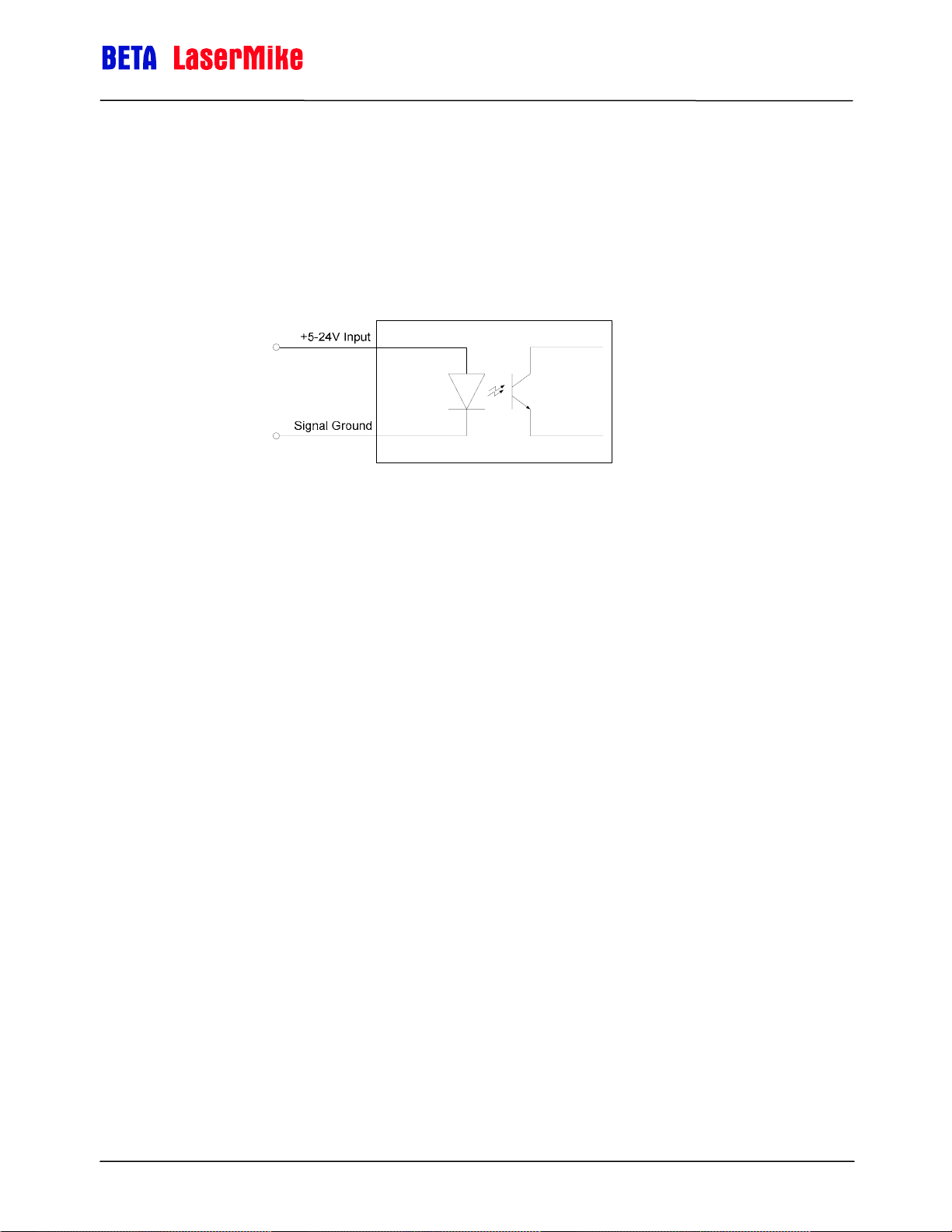
LaserSpeed 8000-3 Instruction Handbook
Interfacing with the LS8000-3
Material Present Input (Pin 10)
This is an optically isolated input that can be used to externally control the
Material Present feature of the LS8000-3. The input requires a voltage high (5
to 24V) to activate. The input level should be the same as the voltage
connected to the User V
the User V
input.
IN
input (Pin 20) or 5V if there is nothing connected to
IN
Optically Isolated Input Schematic
The LS8000-3 can internally sense Material Present, but there are situations
where it is advantageous to determine this externally. This input can also be
used to start and stop length measurements. This input is typically used in the
following situations:
Continuous Processes such as Cold Mills, where there is always metal
in front of the gauge. The input can be used both to start/stop length
measurements, and to prevent the LS8000-3 from sending speed
data/pulses to the PLC while the line is stopped. The LS8000-3 can be
configured to clear the measured velocity to 0 and hold the pulse
outputs when the Material Present input is in the "Material Not Present"
state.
Discrete Part Length applications can take advantage of this input to
increase the precision of length measurements. Two material
detection gauges (such as optical make/break gauges) can be
mounted on either side of the LS8000-3
This input is functional only when the Material Present Input Mode has been
set to External Mode. Activating this input causes a new measurement to
begin. This resets the current length, and resumes counting at 0.
Deactivating this input causes the current measurement to end, which causes
the length to hold at the current value. If in Final Length Mode, the final length
will be output on the RS-232/RS-422/Ethernet port. The functionality of this
input varies with the Material Present Input Mode. The Material Present Input
Mode is configurable through LaserTrak, or by using the “S” serial command.
Part No. 93463 / Drawing No. 0921-01561 Page 43 of 221 Revision A (Sep 2007)
Page 44
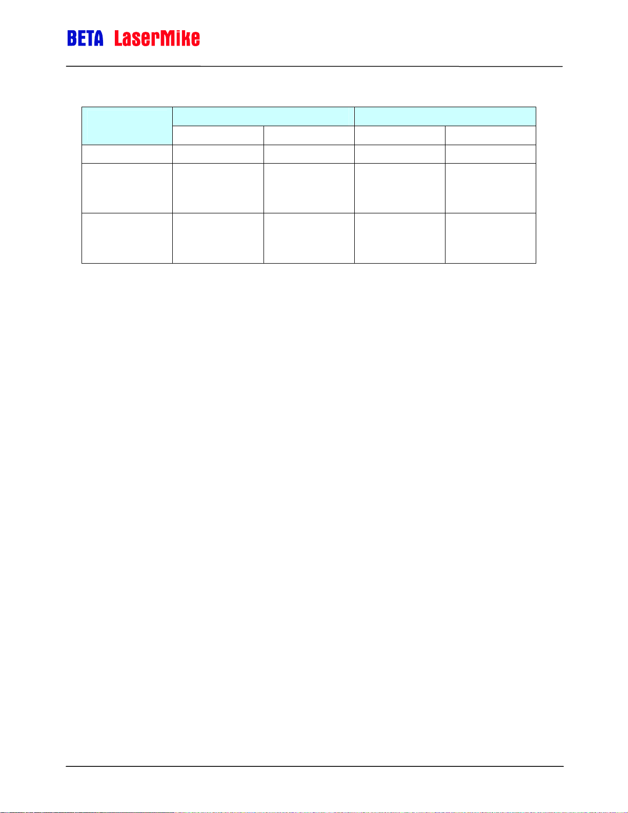
LaserSpeed 8000-3 Instruction Handbook
Interfacing with the LS8000-3
Material Present
Input Mode
0 (Internal) N/A N/A No Effect No Effect
1
(External Active
Low)
2
(External Active
High)
High (5-24V) Low (0V) LowHigh HighLow
("Material Not
("Material Is
Material Present Transition Effect
No
Present")
Yes
Present")
Yes
("Material Is
Present")
No
("Material Not
Present")
Ends Current
Measurement
Starts New
Measurement
Starts New
Measurement
Ends Current
Measurement
Note: If Material Present functionality isn't required, and you want Material
Present to always be on, then set the LS8000-3's Material Present
Input Mode to External Active Low, and leave the Material Present
Input disconnected.
Part No. 93463 / Drawing No. 0921-01561 Page 44 of 221 Revision A (Sep 2007)
Page 45
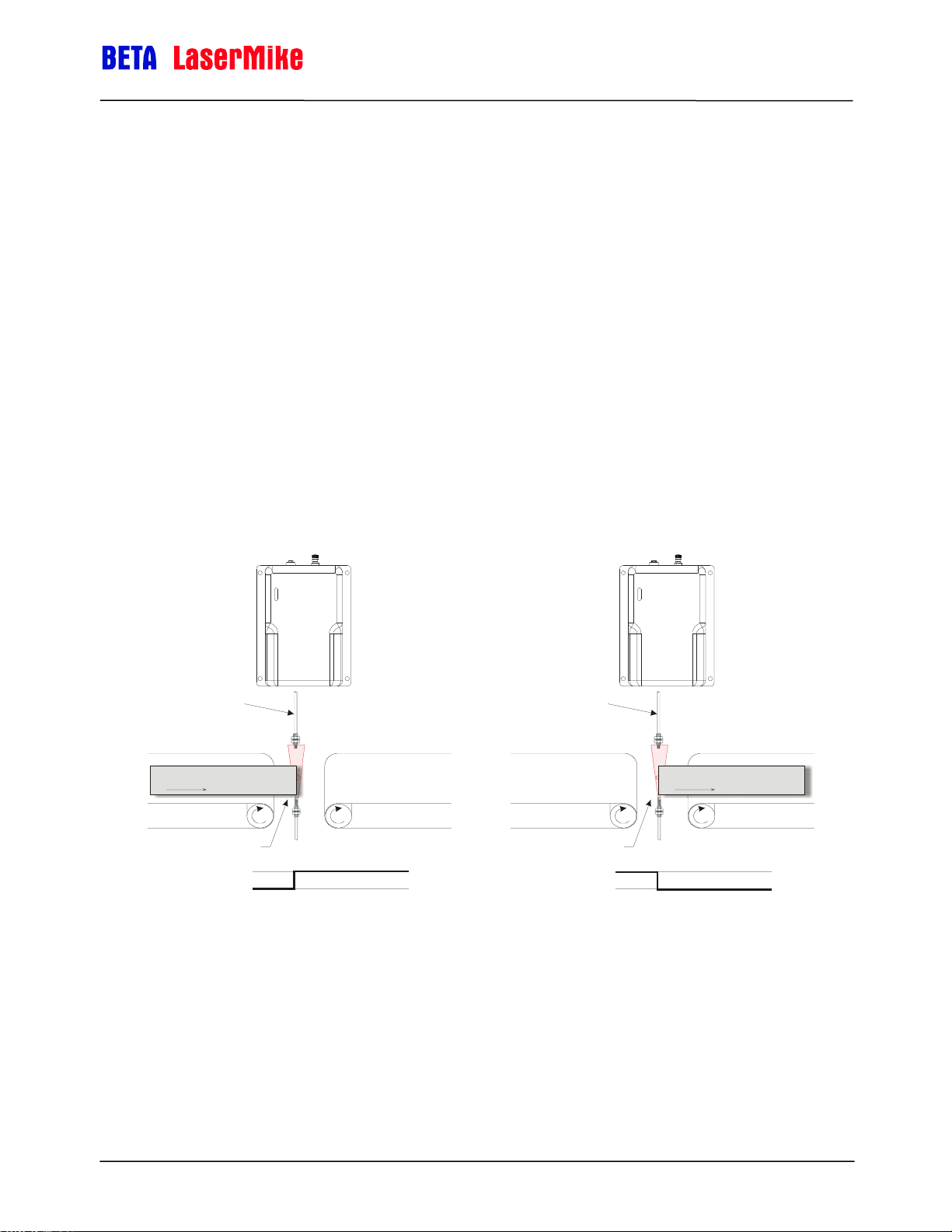
LaserSpeed 8000-3 Instruction Handbook
Interfacing with the LS8000-3
Example 1:
You are using an external make/break optical switch to begin and end the
measurement. The optical gauge has a smaller spot size than the LS8000-3,
so it will more exactly detect the edge of the product. When the part enters the
measurement area the switch outputs a Low (0V) signal, and when there is a
part in the measurement area, the switch outputs a High (24V) signal. So,
when the part enters the measurement area, a LowHigh transition occurs,
and when the part exits the measurement area, a HighLow transition occurs.
This configuration requires that you set the Material Present Input Mode to 2
(External/Active High). When the part enters the measurement area
(LowHigh) a measurement begins, and when the part exits the
measurement area (HighLow) the measurement ends. If the LS8000-3 is in
Final Length Mode, the elapsed length will be transmitted over the serial port
when the part exits the measurement area.
Optical Make/Break
Sensor Fibers
Part to be measured
Line movement
Part Breaks Sensor Beam
Material Present Input
Optical Make/Break
Sensor Fibers
Part Clears Sensor Beam
Material Present Input
Part to be measured
Line movement
Part No. 93463 / Drawing No. 0921-01561 Page 45 of 221 Revision A (Sep 2007)
Page 46

LaserSpeed 8000-3 Instruction Handbook
Interfacing with the LS8000-3
Connecting Material Present Switches
This section shows how to connect a commonly used Material Present
detector.
Single Switch Configuration
The D10 is a make/break optical switch. When connecting one optical switch,
it should be aligned with the LS8000-3's measurement spot. This
configuration can be used in order to more precisely detect the edge of the
material. The fiber optic elements are much smaller than the LS8000-3 spot
size, so repeatability is improved by more consistent edge detection.
Banner Engineering
D10 Expert Fiber-Optic Sensor
Model D10DPFP(Q)
BROWN
BLUE
WHITE
BLACK
GRAY
PINK
+12-24VDC Power
_
1
2
Te a c h
Gate
Material Present (Pin 10)
Signal Ground
(Pin 11, 19, 21)
Material Present Input
Light or Dark Operate
The switch can be configured for either Light Operate or Dark Operate. When
in Light Operate mode, the switch will output a voltage high when there is not
an object blocking the beam, and when in Dark Operate mode, the switch will
output a voltage high when there is an object blocking the beam. Also, the
switch should be configured for Super High Speed (SHS) mode in order to
minimize latency.
Optical Switch Mode LS8000-3 Material Present Mode
Light Operate External Active Low
Dark Operate External Active High
Part No. 93463 / Drawing No. 0921-01561 Page 46 of 221 Revision A (Sep 2007)
Page 47

LaserSpeed 8000-3 Instruction Handbook
Interfacing with the LS8000-3
When the product enters the measurement area and triggers the switch, the
Material Present signal should activate. This causes the LS8000-3 to start
counting length at 0. When the product leaves the measurement area and the
Material Present signal deactivates, the LS8000-3 will calculate the final length
and the measurement is complete. If in Final Length mode, the LS8000-3 will
transmit the Final Length over the serial/Ethernet ports.
Dual Switch Configuration
Two optical switches can be connected in parallel in order to further increase
the precision of part-length measurements. This configuration is typically used
on discrete part measurements that are long and have a very tight length
specification. The LS8000-3 repeatability specification is ±0.02% of the
measured length.
Example:
A cut-to-length application has a product that varies from 14 ft. (4.27m) to 16
ft. (4.88m) in length, and has a tolerance of ±1/8 inch (±0.125in./±3.2 mm.)
The LS8000-3 repeatability specification for a 16 ft. length is a little more than
±1/32 inch (±0.97mm.) While this is better than the length specification, the
measurement variation is only about ¼ the length specification. Ideally, a
measurement instrument's variation should be 10X smaller than the
specification it is required to measure.
In order to improve repeatability, the LS8000-3's measured length can be
reduced by using two optical switches to gate the LS8000-3's measurements.
The LS8000-3 will only measure while the product blocks both optical
switches. In this case, since the minimum part length is 14 ft (4.27m), the
switches could be placed 13 ft (3.96m) apart. This will reduce the length that
the LS8000-3 measures to between 1 and 3 feet. The repeatability will then
be ±0.02% of 1-3ft instead of ±0.02% of 12-16ft. The new repeatability would
then be ±0.0072 inch (0.18mm.) Because the distance between the two
switches is fixed, this value can be added to each length measurement that
the LS8000-3 produces using the Length Reset Value Setting ($R
configuration setting.)
The optical switches should be arranged and wired as shown below:
Part No. 93463 / Drawing No. 0921-01561 Page 47 of 221 Revision A (Sep 2007)
Page 48

LaserSpeed 8000-3 Instruction Handbook
g
Interfacing with the LS8000-3
Entrance Sensor Beam
Part to be meas ured
Line movement
Banner Engineerin
D10 Expert Fiber-Optic Sensor
Model D10DPFP(Q)
BROWN
BLUE
WHITE
BLACK
GRAY
PINK
1
2
Te a c h
Gate
Light Operate
Exit Sensor Beam
+12-24VDC Power
_
Signal Ground
Material Present Input
Mode: External Active Low
Material Present (Pin 10)
Signal Ground
BROWN
BLUE
WHITE
BLACK
GRAY
PINK
1
2
Te a c h
Gate
(Pin 11, 19, 21)
Light Operate
Part No. 93463 / Drawing No. 0921-01561 Page 48 of 221 Revision A (Sep 2007)
Page 49

LaserSpeed 8000-3 Instruction Handbook
Interfacing with the LS8000-3
Signal Grounds (Pins 11, 19, 21)
Multiple ground inputs have been supplied for the pulse outputs (High Speed,
User Scaleable, and Index) to provide good references for cabling.
Additionally, two power input pins (24 and 25, 24 VDC) and power input
ground pins (12 and 13) have been provided for cabling ease.
The Signal Grounds (pins 11, 19, and 21) are internally isolated from the
Power Ground (pins 12, 13). The Signal Ground pins are internally connected.
All input and output signals should be referenced to the Signal Grounds, not
the Power Ground. The Power Ground and the Signal Ground can be tied
together if isolation is not required for the application.
Isolation Required between Power Supply and I/O
Part No. 93463 / Drawing No. 0921-01561 Page 49 of 221 Revision A (Sep 2007)
Page 50
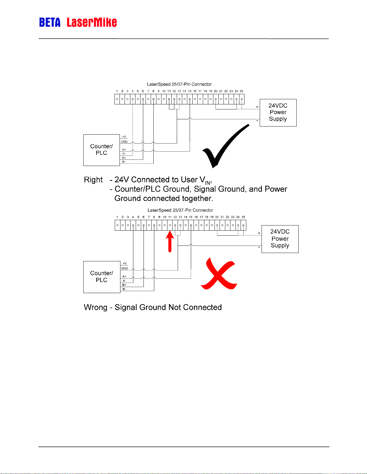
LaserSpeed 8000-3 Instruction Handbook
Interfacing with the LS8000-3
Isolation Not Required between Power Supply and I/O
Part No. 93463 / Drawing No. 0921-01561 Page 50 of 221 Revision A (Sep 2007)
Page 51

LaserSpeed 8000-3 Instruction Handbook
Interfacing with the LS8000-3
Measurement Direction Input (Pin 14)
This is an optically isolated input that can be used to externally control the
Measurement Direction feature of the LS8000-3. The input requires a voltage
high (5 to 24V) to activate. The input level should be the same as the voltage
connected to the User V
the User V
input.
IN
input (Pin 20) or 5V if there is nothing connected to
IN
Optically Isolated Input Schematic
There are two ways to reverse the direction of the LS8000-3's measurements:
1. Modify the Direction Inversion setting with LaserTrak (or using the "A"
serial command)
2. Connect 5-24V to the Measurement Direction Input
Changing the Direction Inversion setting with LaserTrak to invert the direction has
the same effect as changing the state of this input.
Note: If the Direction Inversion setting is set to "Reverse +/- Directions" and
the Measurement Direction Input is high, they will cancel each other
out and the LS8000-3 will operate in the default manner.
Direction
Inversion Setting Measurement Direction Input LS8000-3 Direction
Normal Low (Disconnected or 0v) Normal
Normal High (5-24V) Reversed
Reversed Low (Disconnected or 0v) Reversed
Reversed High (5-24V) Normal
Part No. 93463 / Drawing No. 0921-01561 Page 51 of 221 Revision A (Sep 2007)
Page 52

LaserSpeed 8000-3 Instruction Handbook
Interfacing with the LS8000-3
Laser Interlock (Pin 16)
The Laser Interlock input will switch off the laser power when the connection to
ground is broken. This is commonly used with external switches for laser
safety. When the interlock pin is connected to ground, the laser is operational.
When the interlock circuit is opened (break the connection to ground), power
to the laser is switched off. The power to the rest of the LS8000-3 is not
affected.
Note: To enable laser operation, connect the laser interlock pin (Pin 16) to
ground (Pin 11, 19, or 21). There is a delay of several seconds from
the time the Laser On light turns on to the time that laser radiation is
emitted.
+5V
Laser Interlock (Pin 16)
Safety Interlock Switch
(Close to Turn On Laser)
Signal Ground
(Pin 11, 19, 21)
GND
Laser Interlock Input Circuit
Panel Cutout
for Keyswitch
Lase r Off
Lase r On
0.50in
[12.7mm]
0.42in
[10.7mm]
Laser Interlock Key switch Connection
Part No. 93463 / Drawing No. 0921-01561 Page 52 of 221 Revision A (Sep 2007)
Page 53

LaserSpeed 8000-3 Instruction Handbook
Interfacing with the LS8000-3
Shutter Control (Pin 17)
All Class 3B laser products are required to have a shutter to terminate the
laser beams before exiting the product. The LS8000-3 uses a spring-loaded
rotary solenoid as a laser shutter. The spring-loaded action ensures that when
power is not applied to the shutter circuit, the shutter remains closed.
Note: To open the shutter, connect the shutter control pin (Pin 17) to
ground (Pin 11, 19, or 21).
Panel Cutout
for Keyswitch
Shutte r Closed
Shutte r Open
0.50in
[12.7mm]
0.42in
[10.7mm]
Shutter Interlock Examples
Length Reset Input (Pin 18)
This is an optically isolated input that can be used to externally control the
Length Reset feature of the LS8000-3. The input requires a voltage high (5 to
24V) to activate. The input level should be the same as the voltage connected
to the User V
input.
V
IN
The Length Reset input is used to reset the current length count to zero. This
is the length that is reported over RS-232, RS-422, and Ethernet. The pulse
outputs are not affected by this input.
This can also be accomplished through the "R" command of the serial
command set (see the Communication Protocol
on interfacing with serial commands.
input (Pin 20) or 5V if there is nothing connected to the User
IN
section) for more information
Part No. 93463 / Drawing No. 0921-01561 Page 53 of 221 Revision A (Sep 2007)
Page 54

LaserSpeed 8000-3 Instruction Handbook
)
Interfacing with the LS8000-3
Length Reset Input Circuit
The Length Reset Input Action configuration setting affects how this input
resets the length. The input can be configured to reset the length on level and
edges. See the Length Reset Input Action command description in the
Configuration Settings
User VIN (Pin 20)
Voltage input for Isolated Pulse Outputs, and the Index Pulse Output.
Connecting a voltage from 5-28VDC to this input allows you to control the
pulse amplitude of the LS8000-3 Scaleable Pulse Outputs (Pins 15, 5, 6, 8),
and the Index Pulse Output (Pins 22 and 23.) The voltage supplied will be the
voltage level of the pulse outputs supplied by the LS8000-3. If a voltage is not
supplied, the pulse outputs will be approximately 4.5V.
section for details.
Internal Isolated +5V
Pulse Output
User V
Schematic
IN
Pulse True
Pulse False
User V (Pin 20
Signal Ground
(Pins 11, 19, 21)
User V
GND
User V
GND
IN
IN
IN
Part No. 93463 / Drawing No. 0921-01561 Page 54 of 221 Revision A (Sep 2007)
Page 55

LaserSpeed 8000-3 Instruction Handbook
Interfacing with the LS8000-3
Index (Printer) Pulse Output (Pins 22-23)
Also referred to as a Once-Per-Rev (OPR) pulse, this output can be configured
to output pulses at specified length intervals. This output can be used to
control a cutter or a printer.
For example, if you use LaserTrak to set the “Index Pulse Every X m” setting
to 10m, the gauge would output a single pulse every 10m of product
movement.
The Index pulse will only trigger when the line is moving in the (+) direction. If
the Index Pulse triggers at a certain length, and then the line backs up and
passes that point again, the Index Pulse will not be repeated.
The Index Pulse is asserted for a configurable amount of time. This time can
be configured by changing the Index Pulse Length setting. See the
Configuration Settings
section for details.
Example:
Index Pulse Length = 100ms
Index Pulse Interval = 10m
Index Pulse Output Example
The Index Pulse Output can be reconfigured to output several different status
outputs using the Auxiliary Digital Output Configuration setting. See the
Configuration Settings
section for details.
+24VDC Power Input (Pins 24-25) and Power Grounds (Pins 12-13)
Two Power Input pins and two Power Ground pins are supplied to reduce
voltage drop in long cables. Please see the Connecting Power to the Gauge
section and Appendix D for details concerning power wiring. Pins 24 and 25
and pins 12 and 13 are internally connected in the LS8000-3.
Part No. 93463 / Drawing No. 0921-01561 Page 55 of 221 Revision A (Sep 2007)
Page 56

LaserSpeed 8000-3 Instruction Handbook
DB9 Connector
The 9-pin interface port contains the RS-422 interface pins for high speed,
long distance communication with the LS8000-3, the Analog Output, and the
Measurement Synchronization Input pins. The connector is a standard 9-Pin
male D-Sub connector. It is shown below looking at the gauge's rear panel
with the gauge baseplate down.
Pin Description
Interfacing with the LS8000-3
1 RS-422 Transmit + (from LS8000-3 to host)
2 RS-422 Transmit – (from LS8000-3 to host)
3 RS-422 Receive + (from host to LS8000-3)
4 RS-422 Receive – (from host to LS8000-3)
5 Signal Ground for Inputs/Outputs/Serial
6 Analog Output Voltage
7 Analog Output Ground
8 Measurement Synchronization Input +
9 Measurement Synchronization Input -
RS-422 Transmit (+/-) and Receive (+/-) (Pins 1-4)
These pins comprise the RS-422 interface port. The RS-422 communications
port can be used at speeds up to 230kBaud over long distances. The
transmission cable should be a shielded, twisted pair cable. RS-422 uses
balanced pairs for both transmission and reception, so the +/- lines for the
Transmit and Receive pairs should be paired as shown. To minimize
reflections, the transmit lines from the gauge should be terminated with a
resistor matching the characteristic impedance of the cable (100Ω) as shown
below. The cable shield or drain wire should be attached to the chassis
ground at both ends of the cable. At the gauge end, a DB9 connector with a
metal backshell should be used, and the cable shield should be terminated to
the backshell. The cable jacket should be suitable for the environment to
which the cable will be exposed.
Part No. 93463 / Drawing No. 0921-01561 Page 56 of 221 Revision A (Sep 2007)
Page 57

LaserSpeed 8000-3 Instruction Handbook
Interfacing with the LS8000-3
Cable Jacket
Cable Shield
Drain Wire/Shield
Pin 1 (TX+)
Pin 2 (TX-)
Pin 3 (RX+)
Pin 4 (RX-)
RS-422 Cable
Shield ed,
Two Twisted 100 PairsΩ
RX+
100Ω
RX-
TX+
TX-
Receive
Transmit
Computer/PLC
RS-422 Serial Pinouts
Gauge DB9
Pin Number
1 RS422 Transmit + varies RS422 Receive + (B)
2 RS422 Transmit - varies RS422 Receive – (A)
3 RS422 Receive + varies RS422 Transmit + (B)
4 RS422 Receive - varies RS422 Transmit – (A)
5 Signal Ground varies Signal Ground
Gauge Signal
Description
Computer Pin
Number
Computer Signal
Description
The computer RS-422 pinout can vary with the RS-422 card used. The signal
descriptions listed above should be matched to the signal descriptions listed in
the documentation provided with the RS-422 adapter.
Analog Output Voltage/Ground (Pins 6-7)
Analog Output Specifications
Voltage Range 0-2V
Resolution 12-bit
Minimum ∆V (Step Size) 0.5mV
Load 1kΩ minimum
Filtering 0.1µF Capacitor
Recommended across
Output to Signal Ground
Part No. 93463 / Drawing No. 0921-01561 Page 57 of 221 Revision A (Sep 2007)
Page 58

LaserSpeed 8000-3 Instruction Handbook
Interfacing with the LS8000-3
Analog speed data can be obtained in a 0–2 V format. An optional selectable
voltage/current output module which will convert the 0–2 V signal supplied by
the gauge to all of the common voltage/current levels is available. The analog
output indicates speed but not direction.
There are two configuration settings that affect the operation of the analog
output. The Analog Zero Scale Velocity sets the speed where the analog
output reaches 0V. The Analog Full Scale Velocity sets the speed where the
analog output reaches 2V. At speeds between these two settings, the analog
output increases linearly as the speed increases from the Analog Zero Scale
Velocity to the Analog Full Scale Velocity.
Example: If the Analog Zero Scale Velocity were set to 30 m/min, and the
Analog Full Scale Velocity were set to 100 m/min, the analog output would
behave as shown in the following figure.
1.8
1.6
1.4
1.2
0.8
Analog Output / Volts
0.6
0.4
0.2
Analog Output vs Measured Velocity with VZS = 30 and VFS = 100
2
1
0
0 10 20 30 40 50 60 70 80 90 100 110 120 130 140 150
Measured Velocity
The LS8000's measured speed can be calculated from the analog output
voltage with the following equation:
()
−
VV
ZSFS
+
V
2
≤
V
ZS
≥
V
FS
ZS
when
20
<<
VVoltageV
0
=
VVoltage
2
=
VVoltage
Speed
⎧
Voltage
⎪
⎪
=
⎨
⎪
⎪
⎩
×
where:
= Analog Full Scale Velocity
V
FS
= Analog Zero Scale Velocity
V
ZS
Part No. 93463 / Drawing No. 0921-01561 Page 58 of 221 Revision A (Sep 2007)
Page 59
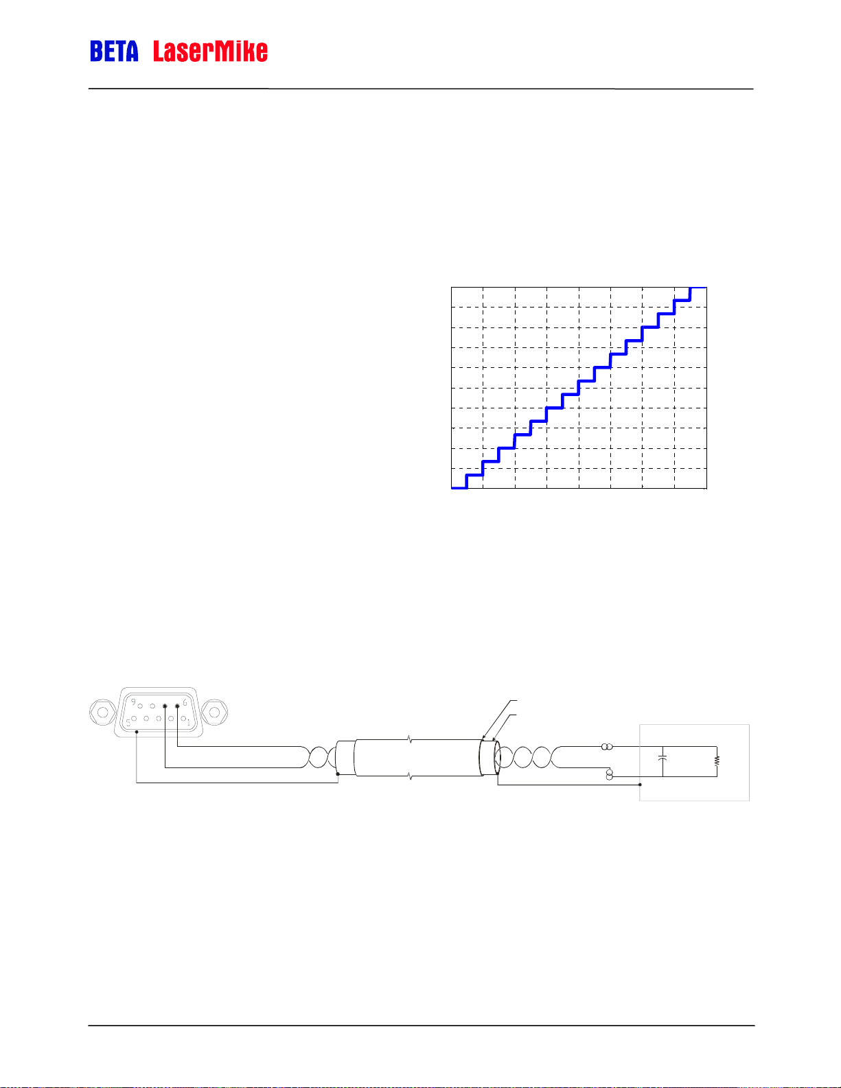
LaserSpeed 8000-3 Instruction Handbook
Voltage = Measured Analog Output Voltage
Note that when the output voltage is at either limit, the exact speed cannot be
determined. If the exact speed is always required, be sure to set the Full
Scale Velocity setting to a value higher than what can normally be
encountered.
Interfacing with the LS8000-3
The analog port can also be configured to
output the QF on a 0–1 V scale by setting
the Full Scale Velocity to zero using a serial
command or LaserTrak software. In this
case, the analog output reads 0V when
the QF is 0 and 1V when the QF is 15.
When the Analog Output is configured to
output Quality Factor, the Quality Factor
can be calculated with the following
equation:
15×= VoltagetorQualityFac
1
0.9
0.8
0.7
0.6
0.5
0.4
Analog Output / Volts
0.3
0.2
0.1
0
0 2 4 6 8 10 12 14 16
Analog Output vs Quality Factor
Quality Fact or
When connecting to the Analog Output Voltage, the Analog Output Voltage
and Analog Output Ground should be on a separate twisted pair inside of a
shielded cable. Connect a 0.1µF capacitor across the load end of the cable
(the end opposite the gauge) to reduce noise caused by other signals in the
cable. See the following wiring example:
Gauge DB9
Cable Jacket
Cable Shield
Analog Output+ (Pin 6)
Analog Output Ground (Pin 7)
Terminate Shield/Drain Wire to backshell of DB9 connector
Analog Outp ut Cable
Shielded, Twisted Pair
Terminate Shield/Drain Wire to
Chassis Ground
0.1 Fµ
1000
Ω
minimum
Analog Output Wiring Example
Measurement Synchronization Input (Pins 8-9)
In many AGC applications, particularly mass flow control, it is desirable to
synchronize the sampling periods of all gauges in the system. This is done by
connecting an LS8000-3 I/O Module to each LS8000-3 in the system (for
Part No. 93463 / Drawing No. 0921-01561 Page 59 of 221 Revision A (Sep 2007)
Page 60
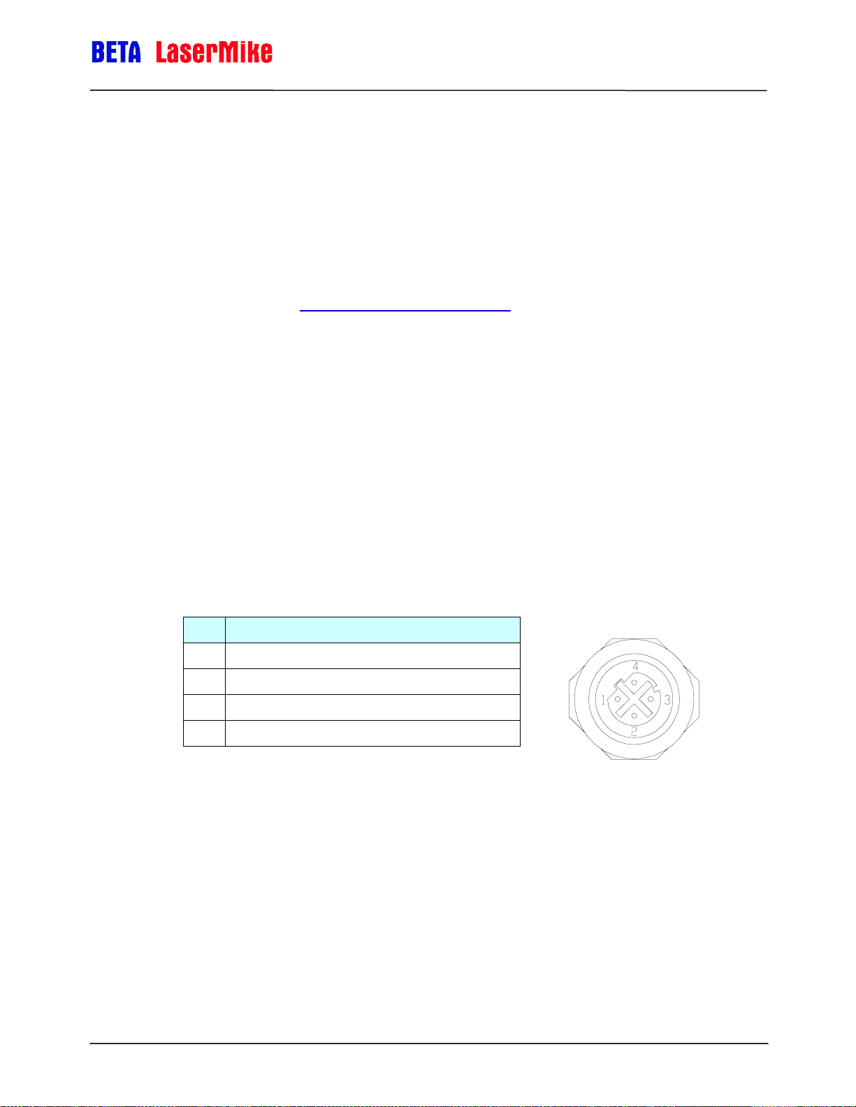
LaserSpeed 8000-3 Instruction Handbook
Interfacing with the LS8000-3
elongation), or by connecting the LS8000-3 gauges together in a daisy-chain
configuration (for synchronization only.)
Using the LS8000-3 I/O Module (one I/O Module per LS8000-3) easily allows
multi-channel synchronization and elongation measurement. The I/O Module
has rear panel Sync connectors that can be connected to other I/O Modules
for synchronization. For details about synchronizing multiple gauges using the
LS8000-3 I/O Module, refer to the LS8000-3 I/O Module Instruction Handbook.
For details about how to connect multiple LaserSpeed gauges together for
synchronization, see the Gauge-Gauge Synchronization
When two or more systems are synchronized, the speed data is synchronous,
although there will be minor variations in the actual output times from one I/O
Module to the next. This means that all processors sample over exactly the
same time period, but due to minute differences in internal processing times,
the output from each processor may arrive a few microseconds earlier or later
than the outputs of the other I/O Modules.
section.
M12 Ethernet Connector
The LS8000-3 Ethernet Connector is a Female, M12, D-Coded Ethernet
connector compatible with most industrial Ethernet patch cables.
LS8000-3 M12 Connector Pinout
Pin Description
1 Ethernet TX+ (from LS8000-3 to host/switch)
2 Ethernet RX+ (from host/switch to LS8000-3)
3 Ethernet TX- (from LS8000-3 to host/switch)
4 Ethernet RX- (from host/switch to LS8000-3)
Beta LaserMike offers a variety of Ethernet cables that can be used to connect
the LS8000-3 to any RJ-45 network jack. Please see the Ethernet Cables
section for a list. To connect directly to a computer, without using an Ethernet
hub or switch, you must use a crossover patch cable.
Please see the Ethernet Communication section for details about the LS80003's Ethernet communication protocol.
Part No. 93463 / Drawing No. 0921-01561 Page 60 of 221 Revision A (Sep 2007)
Page 61
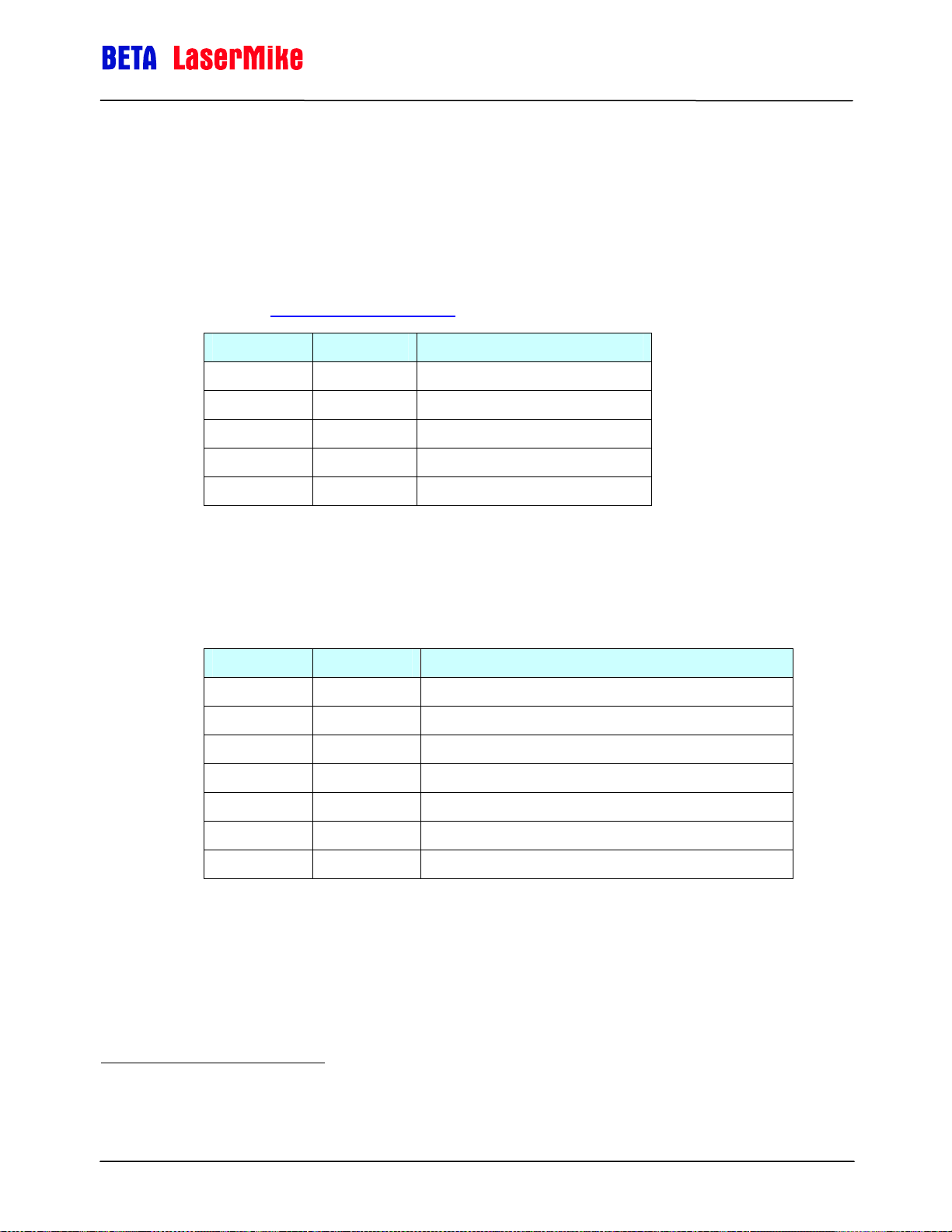
LaserSpeed 8000-3 Instruction Handbook
Interfacing with the LS8000-3
LS8000-3 Interface Cables
DB25 Cables
These cables connect the LS8000-3 25-Pin connector, and are available in
lengths from 3 to 50m. These cables are compatible with all LS4000, LS8000,
and LS8000-3 LaserSpeed gauges. For cables compatible with the E/X
models, see the Heavy Industrial Cables
Part Number Length Cable Description
240211-3M 3m (9.8 ft) CABLE GAUGE-DB25/DB25 3M
240211-10M 10m (32.8 ft) CABLE GAUGE-DB25/DB25 10M
240211-20M 20m (65.6 ft) CABLE GAUGE-DB25/DB25 20M
240211-30M 30m (98.4 ft) CABLE GAUGE-DB25/DB25 30M
240211-50M 50m (164 ft) CABLE GAUGE-DB25/DB25 50M
section.
Ethernet Cables
These cables connect the LS8000-3 M12 Ethernet connector to any standard
Ethernet RJ45 connection.
Part Number Length Cable Description
624581 2m (6.6 ft) CABLE XOVER CAT5E M12 MALE TO RJ45 2M
62410-3M 3m (9.8 ft) CABLE STRANDED CAT5E M12 MALE TO RJ45 - 3M
62410-10M 10m (32.8 ft) CABLE STRANDED CAT5E M12 MALE TO RJ45 - 10M
62411-20M 20m (65.6 ft) CABLE SOLID CAT5E M12 MALE TO RJ45 - 20M
62411-30M 30m (98.4 ft) CABLE SOLID CAT5E M12 MALE TO RJ45 - 30M
62411-50M 50m (164 ft) CABLE SOLID CAT5E M12 MALE TO RJ45 - 50M
62411-100M 100m (328 ft) CABLE SOLID CAT5E M12 MALE TO RJ45 - 100M
1
This is a crossover cable that can be used to connect the LS9000
directly to a PC. This cable should not be used if connecting to a
hub/switch.
Part No. 93463 / Drawing No. 0921-01561 Page 61 of 221 Revision A (Sep 2007)
Page 62

Heavy Industrial Cables
LaserSpeed 8000-3 Instruction Handbook
Interfacing with the LS8000-3
LaserSpeed heavy industrial cables are designed for use in heavy industrial
environments where high temperatures and heavy coolant spray are
encountered. They have an extremely durable outer jacket, and are
impervious to industrial lubricants, coolants, and solvents.
Never pull the cable by the connector. Always attach the pulling cable to
the cable itself. Pulling the cable by the connector may damage the connector
pins. The circular connector has a protective end cap that should be screwed
over the cable pins when pulling through conduit, or any time the cable is
disconnected from the LS8000.
The cable must be screwed onto the LS8000-3 connector until it fully seated—
the yellow stripe on the LS8000-3 connector is not visible when the cable is
fully tightened.
Part No. 93463 / Drawing No. 0921-01561 Page 62 of 221 Revision A (Sep 2007)
Page 63

LaserSpeed 8000-3 Instruction Handbook
Interfacing with the LS8000-3
Part Number Length Cable Description
85277-10M 10m (32.8 ft) CABLE LS3 E/X HSNG CIR/DB37 10M 90ºC
85277-25M 25m (82 ft) CABLE LS3 E/X HSNG CIR/DB37 25M 90ºC
85277-50M 50m (164 ft) CABLE LS3 E/X HSNG CIR/DB37 50M 90ºC
85277-75M 75m (246 ft) CABLE LS3 E/X HSNG CIR/DB37 75M 90ºC
85277-100M 100m (328 ft) CABLE LS3 E/X HSNG CIR/DB37 100M 90ºC
85277-110M 110m (361 ft) CABLE LS3 E/X HSNG CIR/DB37 110M 90ºC
85277-120M 120m (394 ft) CABLE LS3 E/X HSNG CIR/DB37 120M 90ºC
85277-130M 130m (427 ft) CABLE LS3 E/X HSNG CIR/DB37 130M 90ºC
85277-140M 140m (459 ft) CABLE LS3 E/X HSNG CIR/DB37 140M 90ºC
85277-150M 150m (492 ft) CABLE LS3 E/X HSNG CIR/DB37 150M 90ºC
85277-160M 160m (525 ft) CABLE LS3 E/X HSNG CIR/DB37 160M 90ºC
85277-170M 170m (558 ft) CABLE LS3 E/X HSNG CIR/DB37 170M 90ºC
85277-180M 180m (591 ft) CABLE LS3 E/X HSNG CIR/DB37 180M 90ºC
85277-190M 190m (623 ft) CABLE LS3 E/X HSNG CIR/DB37 190M 90ºC
85277-200M 200m (656 ft) CABLE LS3 E/X HSNG CIR/DB37 200M 90ºC
Breakaway Cables
For mills where cobbles, fires, or other conditions may damage the
LaserSpeed cable, a breakaway cable may be appropriate. If the breakaway
cable is damaged, it can be replaced without having to replace the entire
cable.
The LS8000-3 has both a high temperature and low temperature breakaway
cable. The low temperature cable is rated to 90ºC, and is made of the same
construction as the Heavy Industrial Cable. The high temperature cable is
rated to 250ºC, and constructed of special high temperature conductors and
insulation.
Part Number Length Cable Description
85305 10m (32.8 ft) CABLE LS3 E/X LO TEMP BRKAWAY 10M 90ºC
85281 10m (32.8 ft) CABLE LS3 E/X HIGH TEMP BRKAWAY 10M 250ºC
Part No. 93463 / Drawing No. 0921-01561 Page 63 of 221 Revision A (Sep 2007)
Page 64

LaserSpeed 8000-3 Instruction Handbook
Interfacing with the LS8000-3
Low Temperature Breakaway Cable
High Temperature Breakaway Cable
Part No. 93463 / Drawing No. 0921-01561 Page 64 of 221 Revision A (Sep 2007)
Page 65

LaserSpeed 8000-3 Instruction Handbook
Interfacing with the LS8000-3
Breakaway Cable Mounting Bracket
Beta LaserMike Part #: 2306588
The breakaway cable end fastens to this heavy duty bracket to provide support
for the connection between the breakaway cable and the main cable.
Part No. 93463 / Drawing No. 0921-01561 Page 65 of 221 Revision A (Sep 2007)
Page 66

LaserSpeed 8000-3 Instruction Handbook
Interfacing with the LS8000-3
LS8000-3 Breakout Assemblies
For easy interfacing, Beta LaserMike offers several different I/O breakout kits
that connect directly to LaserSpeed cables. These interface blocks are DIN
rail mountable, or can be bolted into a cabinet. Four M5x16 hex head screws
are included.
There are several different options available. The DB25 versions are
compatible with standard LS8000-3 gauges, and the DB37 versions are
compatible with the LS8000-3E/X gauges. Powered and unpowered versions
of both configurations are available. Powered versions have a 24VDC 100W
universal power supply with an input voltage range of 85-264VAC at 47-63Hz.
The power supply can be connected to a standard IEC 320 power cord.
Model Description Compatible With Base Size
85328
85329
85321
85322
85323
85324
ASSY BREAKOUT DB25
LASERSPEED
ASSY BREAKOUT DB25
LASERSPEED POWERED
ASSY BREAKOUT DB37
LASERSPEED
ASSY BREAKOUT DB37
ETHERNET LASERSPEED
ASSY BREAKOUT DB37
LASERSPEED POWERED
ASSY BREAKOUT DB37
ETHERNET LASERSPEED
POWERED
LS8000-3
LS8000-3
LS8000-3E/X
LS8000-3E/X
LS8000-3E/X
LS8000-3E/X
4" x 9"
(102 x 229mm)
4" x 9"
(102 x 229mm)
4" x 12.5"
(102 x 318 mm)
4" x 12.5"
(102 x 318 mm)
4" x 12.5"
(102 x 318 mm)
4" x 12.5"
(102 x 318 mm)
Part No. 93463 / Drawing No. 0921-01561 Page 66 of 221 Revision A (Sep 2007)
Page 67
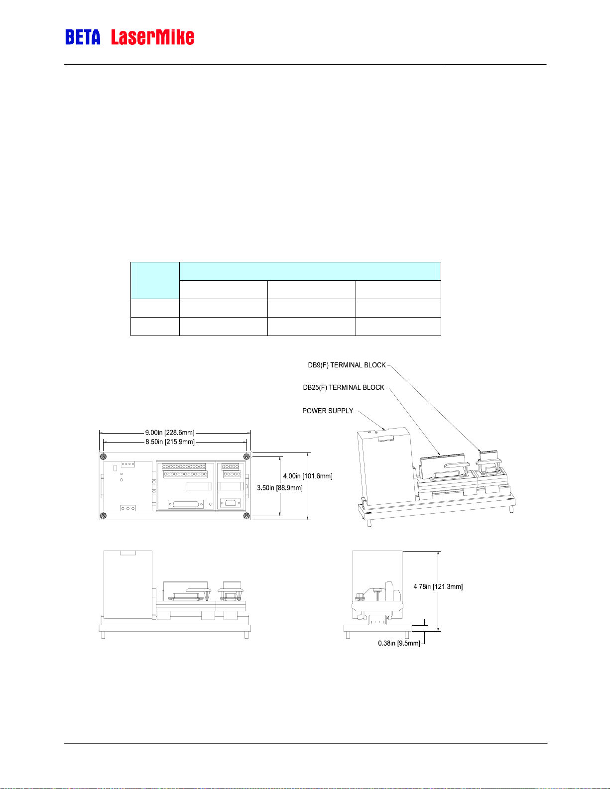
LaserSpeed 8000-3 Instruction Handbook
Interfacing with the LS8000-3
DB25 Breakout Assemblies
Mounting Dimensions for: 85328, 85329
Part Number 85329 is shown in the drawing below. The mounting dimensions
for 85328 and 85329 are identical, with the exception of the height. Part
Number 85328 does not have a power supply, so it has a lower profile. Wiring
is not shown in the drawing.
Interface/Feature Part
Number
85328
85329
LS8000-3 (DB25F) RS-232 (DB9F) Power Supply
Part No. 93463 / Drawing No. 0921-01561 Page 67 of 221 Revision A (Sep 2007)
Page 68

LaserSpeed 8000-3 Instruction Handbook
Interfacing with the LS8000-3
DB37 Breakout Assemblies
Mounting Dimensions for: 85321, 85322, 85323, 85324
Part Number 85324 is shown in the drawing below. The mounting dimensions
for 85321, 85322, 85323, and 85324 are identical, with the exception of the
height. Part Numbers 85321 and 85322 do not have power supplies, so they
have lower profiles.
Part
Number
85321
85322
85323
85324
LS8000-3E/X
(DB37F)
RS-232
(DB9F)
Interface/Feature2
RS-422
(DB9M)
Ethernet
(RJ45)
Power
Supply
2
In this table, an 'F' suffix indicates a Female connector, and an 'M'
suffix indicates a Male connector.
Part No. 93463 / Drawing No. 0921-01561 Page 68 of 221 Revision A (Sep 2007)
Page 69

LaserSpeed 8000-3 Instruction Handbook
Interfacing with the LS8000-3
Breakout Assembly Pinouts
The pinouts for the breakout assembly connectors are listed below. Because
the LaserSpeed cable connects directly to the DB25/DB37 cable, the pinout for
this connector is identical to the gauge cable pinout. See the Connecting to
Outputs section for details.
RS-232 Connector
This Female DB9 connector can be connected to any PC serial port using a
straight-through serial cable with a male connector on one end and a female
connector on the other end. A null modem is not required.
Pin Description DB25/DB37 Pin
2 RS-232 Transmit (from LS8000-3 to host) 1
3 RS-232 Receive (from host to LS8000-3) 2
5 Signal Ground 19
RS-422 Connector
This Male DB9 connector can be connected to an RS-422 input on a PLC, or
an RS-422 converter connected to a PC. Because there is no standard pinout
for RS-422, you may wish to rewire this terminal block to match your cable.
Pin Description DB37 Pin
1 RS422 Transmit + (from LS8000-3 to host) 26
2 RS422 Transmit – (from LS8000-3 to host) 27
3 RS422 Receive + (from host to LS8000-3) 28
4 RS422 Receive – (from host to LS8000-3) 29
Part No. 93463 / Drawing No. 0921-01561 Page 69 of 221 Revision A (Sep 2007)
Page 70
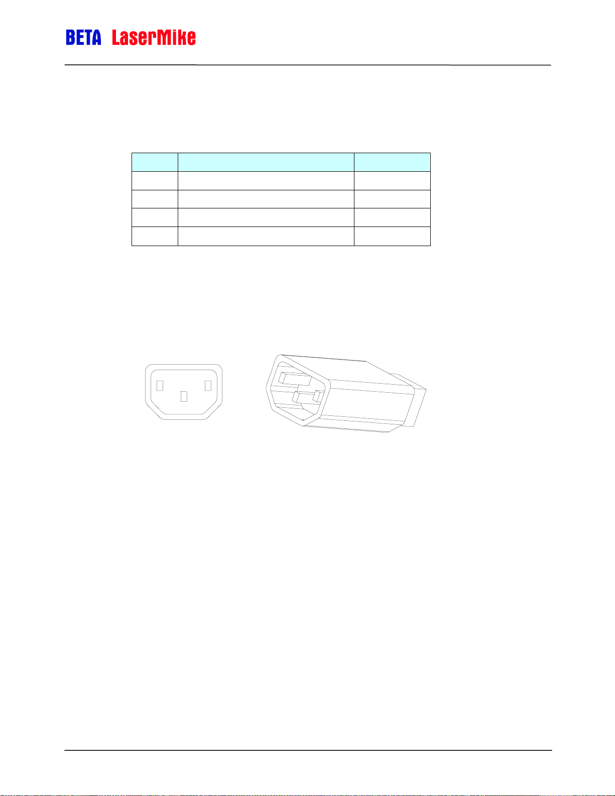
LaserSpeed 8000-3 Instruction Handbook
Ethernet Connector
This RJ45 connector can be connected to any Ethernet hub or switch. A
crossover cable is not required when connecting to a hub or switch, but is
required if connecting directly to a PC.
Pin Description DB37 Pin
1 Ethernet TX+ 34
3 Ethernet TX- 35
2 Ethernet RX+ 36
6 Ethernet RX- 37
Breakout Assembly A/C Power Connector
The powered versions of the breakout assembly have a "kettle plug" style
power connector (IEC 320 sheets C13-14.) This power connector is the most
common in the world, and can be used with most line cords.
Interfacing with the LS8000-3
Part No. 93463 / Drawing No. 0921-01561 Page 70 of 221 Revision A (Sep 2007)
Page 71

LaserSpeed 8000-3 Instruction Handbook
Application Interfaces
Light Stack Interface
The LS8000-3 User Scaleable Pulse Outputs and Index Pulse output can be
reconfigured and connected to a light stack in order to indicate the current
state of the laser in order to warn people in the area of laser radiation. The
pulse outputs can be reconfigured into a light stack interface by setting the
following settings:
Setting Value Command
Index Pulse Output Function Light Stack (Green) #9<CR>
Interfacing with the LS8000-3
User Scaleable Pulse Output
Configuration
The outputs can then be connected to solid state relays in order to drive a light
stack as shown below. This will provide a contact closure for each lamp. The
maximum current that can be driven by this interface will depend on the
selected relay.
Light Stack (Yellow/Red) $L9<CR>
Part No. 93463 / Drawing No. 0921-01561 Page 71 of 221 Revision A (Sep 2007)
Page 72

LaserSpeed 8000-3 Instruction Handbook
The LS8000-3 operates the light stack in the following manner:
Interfacing with the LS8000-3
Light Stack
Lamp
Green Laser is Off No
Yellow
Red
Meaning
Laser is On
Shutter is Closed
Laser is On
Shutter is Open
Laser
Radiation
Emitted?
No
Yes
The light stack should be placed in a conspicuous location near the gauge so
that anyone who may be exposed to laser radiation can easily look at the light
stack to see gauge is emitting laser radiation. The gauge also has an indicator
light labelled "LASER ON" that indicates when the laser is turned on.
Part No. 93463 / Drawing No. 0921-01561 Page 72 of 221 Revision A (Sep 2007)
Page 73

LaserSpeed 8000-3 Instruction Handbook
Interfacing with the LS8000-3
Thermostat Interface
In order to extend the ambient temperature range of LaserSpeed gauges, you
can provide water or air cooling/heating. This is often accomplished by
connecting the gauge to a recirculating heater/chiller, but can also be
accomplished by using the gauge's thermostat output. LaserSpeed gauges
monitor their internal temperatures, and can provide an output indicating when
cooling/heating is required. This output can be connected to a valve or a PLC
in order to control the flow of coolant. The thermostat output is available as an
alternate configuration of the Index Pulse, the High Speed Pulse Output
(Phase B), and the User Scaleable Pulse Output (Phase B.)
Output How To Configure Output Pin Voltage Level
Index Pulse
High Speed
Pulse
User
Scaleable
Pulse
Set Index Pulse Output Function to
Thermostat Output
Set High Speed Pulse Output
Configuration to either:
System Ready/Thermostat Output or
Valid/Thermostat Output
Set User Scaleable Pulse Output
Configuration to either:
System Ready/Thermostat Output or
Valid/Thermostat Output
DB25/DB37 pin 22
DB25/DB37 pin 7
&
DB25/DB37 pin 9
DB25/DB37 pin 6
5-24V, depending on
5-24V, depending on
User Input Voltage
RS-422 Output
(2V-5V Differential)
User Input Voltage
The Thermostat Output turns on (voltage high) when the internal gauge
temperature rises above 40ºC, and turns off when the internal gauge
decreases below 35ºC.
The output can
be connected to
an electrically
operated valve
as shown.
Part No. 93463 / Drawing No. 0921-01561 Page 73 of 221 Revision A (Sep 2007)
Page 74

LaserSpeed 8000-3 Instruction Handbook
Interfacing with the LS8000-3
Index Pulse & Length Thresholds
The Index Pulse and Length Thresholds can be used to control a cutter and
provide pre-cut queues to the process control system so, for example, the line
can be slowed prior to a cut. The Index Pulse is configured to trigger at a
specified length interval, and the Length Thresholds can be configured to
trigger at preset lengths before the Index Pulse triggers. The Length
Threshold outputs remain high until the Index Pulse triggers and resets. The
index pulse automatically resets the Length Threshold outputs—no external
wiring is required.
Another way to reset these outputs is to set the Index Pulse Setting to a high
value and reset the threshold outputs by asserting the Length Reset Input.
The Length Thresholds are available as an alternate output function of the
User Scaleable Pulse Output.
Example:
Setting Value
Index Pulse Setting 100 m
Index Pulse Length 100 ms
Length Threshold A 90 m
Length Threshold B 80 m
Part No. 93463 / Drawing No. 0921-01561 Page 74 of 221 Revision A (Sep 2007)
Page 75

LaserSpeed 8000-3 Instruction Handbook
Interfacing with the LS8000-3
Gauge-Gauge Synchronization
LaserSpeed LS9000 and LS8000 gauges can be synchronized so that their
sampling periods are synchronized, and so they update their outputs at the
same time.
The simplest method for synchronizing gauges is to connect each gauge to a
LaserSpeed I/O module and connect the I/O Modules' synchronization
connects together. The I/O Modules will automatically synchronize the gauges
and calculate elongation, which can be output in a variety of different ways.
Another method for synchronization is to reconfigure the gauges' High Speed
Pulse Output ports and connect the gauges together in a daisy-chain
configuration. The gauges will synchronize to each other, but will not calculate
elongation. If an elongation calculation is required, the RS232, RS422, or
Ethernet output data from each gauge must be collected and calculated in an
external PLC or computer.
To configure the High Speed Pulse Output to output the synchronization
signal, use LaserTrak to set the High Speed Pulse Config option "A=Pulse
Phase A, B=Sync Out". This will replace the pulse output phase B with the
synchronization output, and will leave Phase A available for connection to a
counter.
Part No. 93463 / Drawing No. 0921-01561 Page 75 of 221 Revision A (Sep 2007)
Page 76
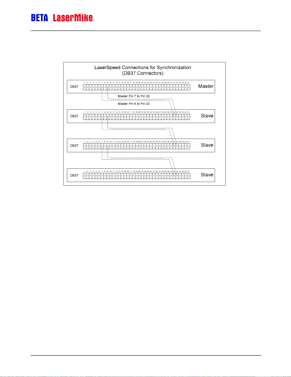
LaserSpeed 8000-3 Instruction Handbook
Interfacing with the LS8000-3
Part No. 93463 / Drawing No. 0921-01561 Page 76 of 221 Revision A (Sep 2007)
Page 77

LaserSpeed 8000-3 Instruction Handbook
Banner D10 Through Beam Switch
Single through beam
Signal D10 LaserSpeed
Power (+12 v to +24v) Brown N/A
Material Present White 10
Signal Ground Blue 11
Notes:
Use with a LaserSpeed 4000-2, 8000-2, 8000-3 or 9000-3
Interfacing with the LS8000-3
See the Connecting Material Present Switches
section for wiring
Program the LaserSpeed for material present “external – active high”
Program the D10 module for Super High Speed output
You may have to teach the D10 light and dark levels (refer to D10
manual)
Dual through beam (uses two D10 modules)
Signal D10 LaserSpeed
Power (+12 v to +24v) Brown N/A
Material Present Black 10
Signal Ground Blue 11
Notes:
Use with a LaserSpeed 4000-2, 8000-2, 8000-3 or 9000-3
See the Connecting Material Present Switches
Program the D10 module for Super High Speed output
Program the LaserSpeed for material present “external – active low”
section for wiring
You may have to teach the D10 light and dark levels (refer to D10
manual)
The distance between the switch pairs needs to be added to the length
reported by the LaserSpeed
Part No. 93463 / Drawing No. 0921-01561 Page 77 of 221 Revision A (Sep 2007)
Page 78
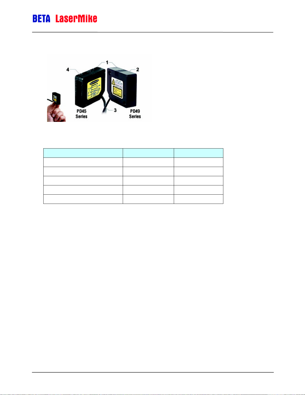
LaserSpeed 8000-3 Instruction Handbook
Banner Retroflective Switch (Picodot)
Pinout
Signal PD45 LaserSpeed
Power (+10 v to +30v) Brown See below
Interfacing with the LS8000-3
Material Present White 10
Signal Ground Blue 11
Pullup (4.7K) White (LS pin 10) 24
Laser enable Grey 11
Notes:
Use with a LaserSpeed 4000-2, 8000-2, 8000-3 or 9000-3
Program the LaserSpeed for material present “external – active high”
You can power the banner switch from the LaserSpeed power supply
(pin 25) but you need to connect pins 11 and 12 on the Laserspeed
breakout together.
Part No. 93463 / Drawing No. 0921-01561 Page 78 of 221 Revision A (Sep 2007)
Page 79

DataPro 1000
Quadrature Pinout
LaserSpeed 8000-3 Instruction Handbook
Interfacing with the LS8000-3
Signal DP1K LaserSpeed
Signal A 36 15
Signal A- 34 4
Signal B 32 6
Signal B- 30 8
Signal Ground 25 11
User Voltage 27 20
Pulsed Pinout
Signal DP1K LaserSpeed
Signal A 28 15
Signal A- 26 4
Signal Ground 25 11
User Voltage 27 20
Notes:
Configure the LaserSpeed pulse per unit length
Remove jumpers JL6, JL7, JL10 and JL11 if required in differential-
input configuration
Part No. 93463 / Drawing No. 0921-01561 Page 79 of 221 Revision A (Sep 2007)
Page 80

DataPro 3000
LaserSpeed 8000-3 Instruction Handbook
Interfacing with the LS8000-3
Pinout
Signal DP3K DB25 LaserSpeed
Signal A 11 15
Signal Ground 24 11
User Voltage 1 20
Notes
Configure the LaserSpeed pulse per unit length
Part No. 93463 / Drawing No. 0921-01561 Page 80 of 221 Revision A (Sep 2007)
Page 81

DataPro 5000 BB
LaserSpeed 8000-3 Instruction Handbook
Interfacing with the LS8000-3
Quadrature Pinout
Signal DP5K LaserSpeed
Signal A 22 15
Signal A- 23 4
Signal B 24 6
Signal B- 25 8
Signal Ground 28 11
User Voltage 29 20
Pulsed Pinout
Signal DP5K LaserSpeed
Signal A 5 15
Signal A- 23 4
Signal Ground 28 11
User Voltage 29 20
Notes:
Configure the LaserSpeed pulse per unit length
Part No. 93463 / Drawing No. 0921-01561 Page 81 of 221 Revision A (Sep 2007)
Page 82

DataPro 5000 DN
LaserSpeed 8000-3 Instruction Handbook
Interfacing with the LS8000-3
Quadrature Pinout
Signal DP5K LaserSpeed
Signal A J1-1 15
Signal A- J1-2 4
Signal B J2-1 6
Signal B- J2-2 8
Signal Ground 12 11
User Voltage 25 20
Pulsed Pinout
Signal DP5K LaserSpeed
Signal A J3-1 15
Signal A- J3-2 4
Signal Ground 12 11
User Voltage 25 20
Notes:
Configure the LaserSpeed pulse per unit length
Part No. 93463 / Drawing No. 0921-01561 Page 82 of 221 Revision A (Sep 2007)
Page 83

DataPro 5000 DN – Beckhoff I/O
LaserSpeed 8000-3 Instruction Handbook
Interfacing with the LS8000-3
Quadrature Pinout
Signal KL5101-A LaserSpeed
Signal A (KL5101-A) 1 15
Signal A- (KL5101-A) 5 4
Signal B (KL5101-A) 2 6
Signal B- (KL5101-A) 6 8
Signal Ground (DP5K I/O) 12 11
User Voltage (DP5K I/O) 25 20
Pulsed Pinout
Signal KL5111-A LaserSpeed
Signal A (KL5111-A) 5 15
Signal Ground (DP5K I/O) 12 11
User Voltage (DP5K I/O) 25 20
Notes:
Configure the LaserSpeed pulse per unit length
Part No. 93463 / Drawing No. 0921-01561 Page 83 of 221 Revision A (Sep 2007)
Page 84
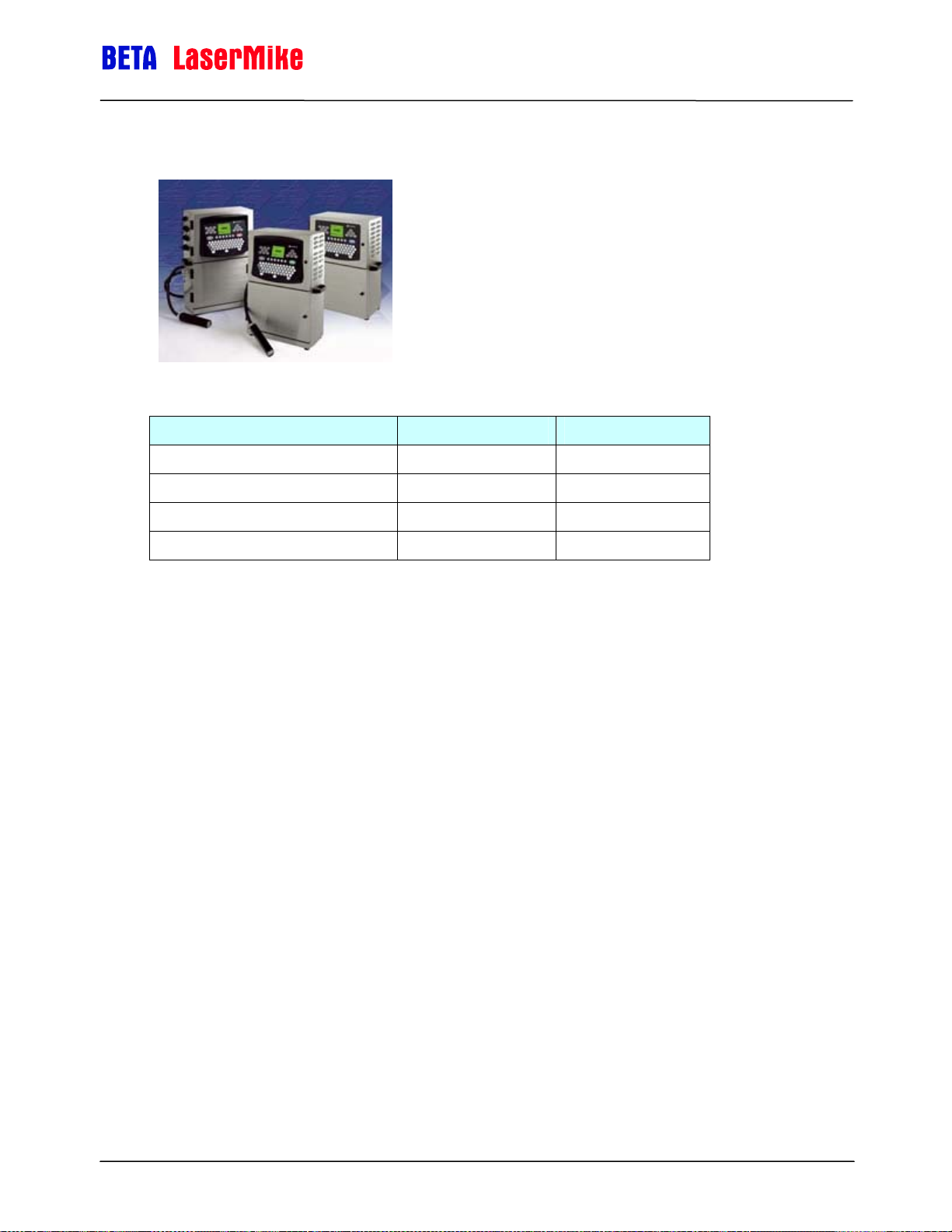
Domino A Series
Pinout
Signal Domino A200 LaserSpeed
Signal A 2 15
Print Go 3 22
LaserSpeed 8000-3 Instruction Handbook
Interfacing with the LS8000-3
Signal Ground 1 11
User Voltage 4 20
Notes:
Configure the LaserSpeed for the appropriate pulse per unit length.
The index pulse should be set to trigger at the appropriate rate (every 2
feet, every 1 meter, etc), and with a 20 ms pulse width.
On the Domino A-Series printer, the Strobe Divide should be set to 1.
There are two ports that are in parallel so it doesn’t matter which one is
used. The other port would not be used. The printer should be set for
EXTERNAL print and the REPEAT PRINTING should be turned off.
Part No. 93463 / Drawing No. 0921-01561 Page 84 of 221 Revision A (Sep 2007)
Page 85

LaserSpeed 8000-3 Instruction Handbook
Durant President Series
Quadrature Pinout
Signal Durant LaserSpeed
Interfacing with the LS8000-3
Signal A 14 15
Signal B 10 6
Signal Ground 12 11
User Voltage 20 20
Pulsed Pinout
Signal Durant LaserSpeed
Signal A 14 15
Signal Ground 12 11
User Voltage 20 20
Notes:
Configure the LaserSpeed pulse per unit length
Set scaling in the Durant counter
Set count mode in the Durant (single, quad, quad x2…)
Part No. 93463 / Drawing No. 0921-01561 Page 85 of 221 Revision A (Sep 2007)
Page 86

LaserSpeed 8000-3 Instruction Handbook
Durant Settings
Func # Value
5 0.005
60 2
62 1
63 1
64 0.3000.0
LaserSpeed must be configured for 1000 pulses per unit (ft or m)
Part No. 93463 / Drawing No. 0921-01561 Page 86 of 221 Revision A (Sep 2007)
Page 87

Hengstler 723.1
LaserSpeed 8000-3 Instruction Handbook
Quadrature Pinout
Signal Hengstler LaserSpeed
Signal A 30 15
Signal B 29 6
Signal Ground 31 11
User Voltage 32 20
Pulsed Pinout
Signal Hengstler LaserSpeed
Signal A 30 15
Signal Ground 31 11
User Voltage 32 20
Notes:
Configure the LaserSpeed pulse per unit length
Set scaling in the Hengstler counter
Set count mode in the Hengstler counter (single, quad, quad x2…)
Part No. 93463 / Drawing No. 0921-01561 Page 87 of 221 Revision A (Sep 2007)
Page 88

LaserSpeed 8000-3 Instruction Handbook
Imaje S4/S8
Pinout
Signal Imaje S4/S8 LaserSpeed
Signal A T1-8 8
Print Go T1-4 22
Signal Ground T1-1 and T1-3 11
User Voltage T1-7 20
Notes:
The programmable pulse output of the LaserSpeed needs to be set to
5000 or 10000 pulses/m depending on the setting in the Imaje printer.
The Index Pulse Output from the LaserSpeed needs to be set to 1
pulse per meter.
Part No. 93463 / Drawing No. 0921-01561 Page 88 of 221 Revision A (Sep 2007)
Page 89

MI800
Quadrature Pinout
Signal MI800 LaserSpeed
LaserSpeed 8000-3 Instruction Handbook
Signal A B 15
Signal B C 6
Signal Ground A 11
User Voltage D 20
Notes:
Configure the LaserSpeed pulse per unit length
Part No. 93463 / Drawing No. 0921-01561 Page 89 of 221 Revision A (Sep 2007)
Page 90

Newport P6000A
Pulsed Pinout
LaserSpeed 8000-3 Instruction Handbook
Signal Newport LaserSpeed
Signal A TB2 1 15
Signal Ground TB2 3 11
User Voltage P2 8 20
Notes:
Configure the LaserSpeed pulse per unit length
Set scaling in the Newport counter
Set count mode in the Newport counter (single, quad, quad x2…)
Part No. 93463 / Drawing No. 0921-01561 Page 90 of 221 Revision A (Sep 2007)
Page 91

Red Lion PAXI
LaserSpeed 8000-3 Instruction Handbook
Quadrature Pinout
Signal PAXI LaserSpeed
Signal A 5 15
Signal B 6 6
Signal Ground 4 11
User Voltage 2 20
Pulsed Pinout
Signal PAXI LaserSpeed
Signal A 5 15
Signal Ground 4 11
User Voltage 2 20
Notes:
Configure the LaserSpeed pulse per unit length.
Set scaling in the PAXI.
Set count mode in the PAXI (single, quad, quad x2…).
Part No. 93463 / Drawing No. 0921-01561 Page 91 of 221 Revision A (Sep 2007)
Page 92
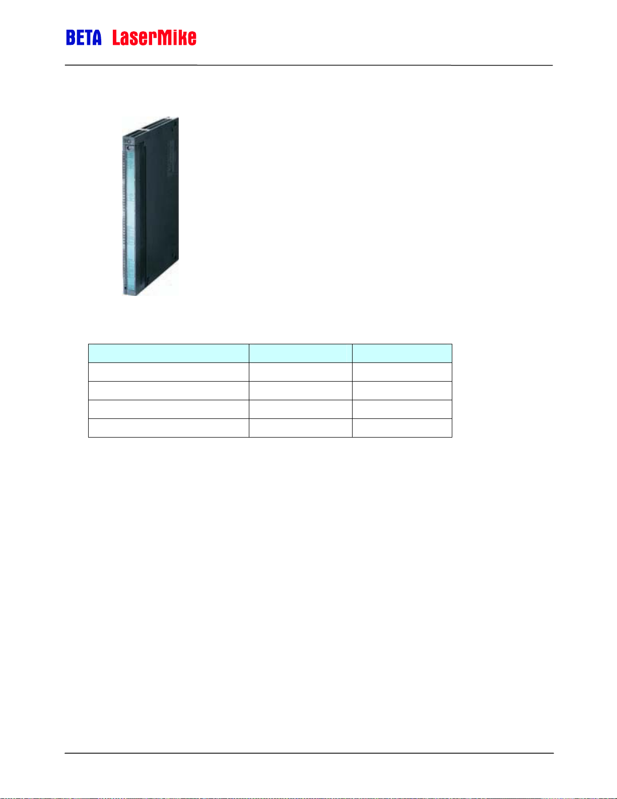
Siemens Counter Module 450-1
LaserSpeed 8000-3 Instruction Handbook
Quadrature Pinout
Signal 450-1 LaserSpeed
Signal A 23 15
Signal B 24 6
Signal Ground 26 11
User Voltage 28 20
Notes:
Configure the LaserSpeed pulse per unit length
Set scaling in the 450-1
Part No. 93463 / Drawing No. 0921-01561 Page 92 of 221 Revision A (Sep 2007)
Page 93

LaserSpeed 8000-3 Instruction Handbook
Siemens Counter Module 6ES5 385-8MB11
Quadrature Pinout
Signal Siemens LaserSpeed
Signal A 7 15
Signal A-N 6 4
Signal B 9 6
Signal B-N 10 8
Signal Ground 3 11
User Voltage 1 20
Pulsed Pinout
Signal Siemens LaserSpeed
Signal A 7 15
Signal A-N 6 4
Signal Ground 3 11
User Voltage 1 20
Notes:
Configure the LaserSpeed pulse per unit length
Set scaling in the Siemens counter
Set count mode in the Siemens counter (single, quad, quad x2…)
Part No. 93463 / Drawing No. 0921-01561 Page 93 of 221 Revision A (Sep 2007)
Page 94

LaserSpeed 8000-3 Instruction Handbook
TrueMeter
Quadrature Pinout
Signal TrueMeter LaserSpeed
Signal A 3 15
Signal B 2 6
Signal Ground 1 11
User Voltage 4 20
Pulsed Pinout
Signal TrueMeter LaserSpeed
Signal A 3 15
Signal Ground 1 11
User Voltage 4 20
Notes:
Configure the LaserSpeed pulse per unit length
Set scaling in the TrueMeter counter
Set count mode in the TrueMeter counter (single, quad, quad x2…)
Part No. 93463 / Drawing No. 0921-01561 Page 94 of 221 Revision A (Sep 2007)
Page 95

LaserSpeed 8000-3 Instruction Handbook
LaserTrak Software
LaserTrak® is a Windows®-based software program, which allows you to
acquire and display the Length, Velocity, Quality Factor, and Gauge Status in
real time. The LaserTrak software configures the respective gauge’s operating
parameters, displays data, and collects data, which can be stored to a
computer hard drive. This LaserSpeed series of non contact speed and length
gauges provide a set of versatile tools that are applicable for a wide variety of
process measurement schemes. LaserTrak allows you to take full advantage
of this versatility in a straightforward, easy to understand manner.
There are several features available with the LaserTrak software. LaserTrak
mimics a chart recorder output on the screen and monitor the speed, length
and Quality Factor in real time and presents a time history depiction of the
data. LaserTrak can acquire and store data, and load and display stored data
from a previously acquired data file.
LaserTrak Software
LaserTrak for Windows
Note: LaserTrak Version 4.0 or later must be used with the LS8000 gauge.
Installing the LaserTrak Software
This section includes the information you need to install and begin using your
copy of LaserTrak:
System Requirements
500 MHZ Pentium Computer Minimum (2 GHz Pentium Computer
recommended)
Windows 98, NT, 2000 or XP (Windows 2000 or XP recommended)
256 MB RAM
15" Monitor or bigger
50 MB of Hard Drive Space
Part No. 93463 / Drawing No. 0921-01561 Page 95 of 221 Revision A (Sep 2007)
®
Windows 98, NT 2000 and Windows XP are registered trademarks of Microsoft
Corporation.
Page 96

LaserSpeed 8000-3 Instruction Handbook
Software Installation Procedure
Complete the following steps to install the LaserTrak software:
1) Insert the LaserTrak for Windows Setup CD into your CD-ROM
drive.
2) From the Start menu select Run.
3) Browse to the LaserTrak_4_Setup.exe program on the CD-ROM
Drive and select it.
4) Press OK.
The setup program installs the software into the default
directory “c:\Program Files\BLM LaserTrak 4.0”. The
install program gives you a chance to accept the default
directory or install it in a directory of your own choosing.
The setup program does the following:
LaserTrak Software
1) Creates a folder and group for the LaserTrak
program and files and puts the LaserTrak
program icon into your desktop.
2) BLM LaserTrak 4.0 is added to the Windows
StartPrograms menu under BLM LaserTrak 4.0
Starting LaserTrak
Once the LaserTrak software has been installed the LaserTrak software will
automatically start. If LaserTrak does not automatically start, go to the Start
Menu and click on the LaserTrak program…
… or double click the LaserTrak Icon on your desktop.
Part No. 93463 / Drawing No. 0921-01561 Page 96 of 221 Revision A (Sep 2007)
Page 97

LaserSpeed 8000-3 Instruction Handbook
Note: Make sure that the LaserSpeed gauge is connected to the computer
via RS232, RS422 or Ethernet before starting the LaserTrak
software. The first thing the LaserTrak software does is establish
communication between the LaserSpeed gauge and the computer. If
no gauge is connected, communication will not be established and
you will see the following screen.
If you get the Gauge Not Found message, you can still run LaserTrak by
recalling and displaying stored data.
LaserTrak Software
LaserTrak will display
the following screen
when starting up if
communication has
been established
between the gauge
and the software.
Part No. 93463 / Drawing No. 0921-01561 Page 97 of 221 Revision A (Sep 2007)
Page 98

LaserSpeed 8000-3 Instruction Handbook
The Communication screen will then be displayed showing the COM port and
BAUD rate and communication parameters it found to communicate with the
gauge.
LaserTrak Software
Click the OK button to go to the Chart Recorder Screen. The
Chart Recorder screen will acquire Speed, Length, Quality Factor
and Status data from the LaserSpeed gauge and display it. The
Speed and Quality Factor will be displayed graphically and the
Length and Status information will be displayed in a table format.
Press the Start Readings button to acquire data from the gauge.
The Start Readings button will change to Stop Readings button.
Press the Stop Readings button to stop acquiring data from the
gauge. The graph, Graph Info and Gauge Status will only be
active when acquiring data from the gauge, and the Stop
Reading Button is being displayed. All the data will be frozen on
the Chart Recorder screen when the Stop Readings button is pressed and the
button changes back to Start Readings again.
Shows the COM Port and Settings
used to establish communication
Part No. 93463 / Drawing No. 0921-01561 Page 98 of 221 Revision A (Sep 2007)
Page 99

Chart Recorder Screen
LaserSpeed 8000-3 Instruction Handbook
LaserTrak Software
Gauge Info
Length (m) – the length on the LaserSpeed gauge’s length counter. The
length is accumulation from the last time the gauge was reset.
Length is displayed in the units set during gauge
Configuration.
Vel (m/min) – the instantaneous speed measured by the LaserSpeed
gauge. The speed is displayed in the units set during gauge
Configuration.
QF- the instantaneous Quality Factor measured by the LaserSpeed
gauge. QF is displayed as a number between 0 and 15,
where 15 represents the best and 0 represents no
measurements being made.
Average QF- the average of all the QF readings since the LaserTrak
software started acquiring data from the gauge. This value is
Part No. 93463 / Drawing No. 0921-01561 Page 99 of 221 Revision A (Sep 2007)
Page 100

Gauge Status
LaserSpeed 8000-3 Instruction Handbook
LaserTrak Software
reset every time data acquisition is restarted. Note: This is not
the average of the QF on the display.
Point Record Number- is the number data points acquired since the data
acquisition began.
Time in Sec- the amount of time since the data acquisition began.
Vel. Min IV – the minimum velocity in view (IV) on the velocity graph
Vel. Max IV – the maximum velocity in view (IV) on the velocity graph
Instrument Type – the type of gauge from which LaserTrak is acquiring
data.
Valid Measurement – Yes, if the gauge is making valid measurement,
and No, if it is not making valid measurements.
Material Present – Yes, if material present is detected and No, if material
present is not detected.
Laser At Temp – Yes, if the Laser is within the allowed temperature
range, and No if the Laser is outside its temperature range.
The LS8000 will turn off its Laser if it is outside the allowed
temperature range.
Interlock Closed- Yes, if the interlock is closed and No if the interlock is
open. The Laser will only be on if the interlock is closed.
Shutter Open – Yes, if the internal shutter is open and No if the internal
shutter is close. If the shutter is closed, the Laser beam will
be blocked and no measurements will be made.
User Update Rate – Displayed in Milliseconds: Indicates how fast the
gauge will output readings via RS232, RS422, and Ethernet
Walking Threshold – the gauge will not increment the internal length
counter or output pulses if the speed is below this Walking
Threshold value. The Walking Threshold is set during gauge
Configuration. Set the Walking Threshold to 0 to disable this
feature.
Hold Velocity – Sets the velocity value above which, the last valid reading
is held when no measurements are made, and below which
the LS8000 outputs a zero for the velocity and stops counting
length when no valid measurements are made. The Hold
Part No. 93463 / Drawing No. 0921-01561 Page 100 of 221 Revision A (Sep 2007)
 Loading...