

Page 1
Document 480081
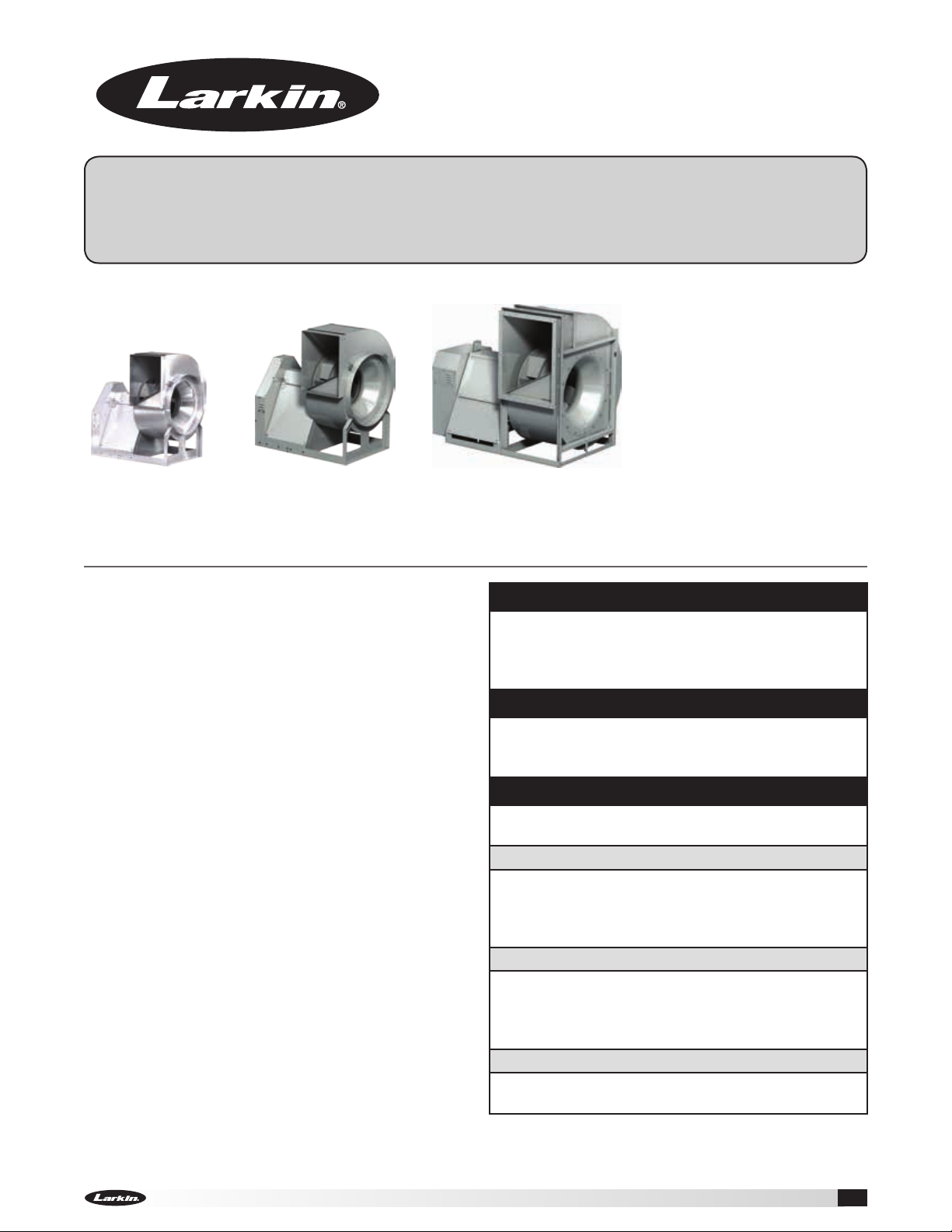
Model XUEF-200, 300 and 400
Utility Fans
Installation, Operation and Maintenance Manual
Please read and save these instructions for future reference. Read carefully before attempting to assemble,
install, operate or maintain the product described. Protect yourself and others by observing all safety
information. Failure to comply with instructions could result in personal injury and/or property damage!
XUEF-200
XUEF-300 XUEF-400
General Safety Information
Only qualified personnel should install this fan.
Personnel should have a clear understanding of these
instructions and should be aware of general safety
precautions. Improper installation can result in electric
shock, possible injury due to coming in contact with
moving parts, as well as other potential hazards.
Other considerations may be required if seismic
activity is present. If more information is needed,
contact a licensed professional engineer before
moving forward.
1. Follow all local electrical and safety codes, as
well as the National Electrical Code (NEC) and the
National Fire Protection Agency (NFPA), where
applicable. Follow the Canadian Electric Code
(CEC) in Canada.
2. The rotation of the wheel is critical. It must be free
to rotate without striking or rubbing any stationary
objects.
3. Motor must be securely and adequately grounded.
4. Do not spin fan wheel faster than max cataloged
fan RPM. Adjustments to fan speed significantly
effects motor load. If the fan RPM is changed, the
motor current should be checked to make sure it is
not exceeding the motor nameplate amps.
5. Do not allow the power cable to kink or come in
contact with oil, grease, hot surfaces or chemicals.
Replace cord immediately if damaged.
6. Verify that the power source is compatible with the
equipment.
7. Never open access doors to a duct while the fan is
running.
DANGER
Always disconnect, lock and tag power source
before installing or servicing. Failure to disconnect
power source can result in fire, shock or serious
injury.
CAUTION
When servicing the fan, motor may be hot enough
to cause pain or injury. Allow motor to cool before
servicing.
CAUTION
Precaution should be taken in explosive
atmospheres.
DANGER
Pour écarter les risques d’incendie, de choc
électrique ou de blessure grave, veiller à toujours
débrancher, verrouiller et étiqueter la source de
courant avant l’installation ou l’entretien.
ATTENTION
Lors de toute intervention sur la soufflante, le moteur
peut être suffisamment chaud pour provoquer
une douleur voire une blessure. Laisser le moteur
refroidir avant toute maintenance.
ATTENTION
Faire preuve de précaution dans les atmosphères
explosives.
Utility Fans 1
Page 2

Receiving
Upon receiving the product, check to ensure all
items are accounted for by referencing the delivery
receipt or packing list. Inspect each crate or carton
for shipping damage before accepting delivery. Alert
the carrier of any damage detected. The customer
will make a notation of damage (or shortage of items)
on the delivery receipt and all copies of the bill of
lading which is countersigned by the delivering
carrier. If damaged, immediately contact your Larkin
Representative. Any physical damage to the unit after
acceptance is not the responsibility of manufacturer.
Unpacking
Verify that all required parts and the correct quantity
of each item have been received. If any items are
missing, report shortages to your local representative
to arrange for obtaining missing parts. Sometimes it
is not possible that all items for the unit be shipped
together due to availability of transportation and truck
space. Confirmation of shipment(s) must be limited to
only items on the bill of lading.
Handling
Fans are to be rigged and moved by the lifting
brackets provided or by the skid when a forklift is
used. Location of brackets varies by model and size.
Handle in such a manner as to keep from scratching
or chipping the coating. Damaged finish may reduce
the ability of the fan to resist corrosion. Fans should
never be lifted by the shaft, fan housing, motor, belt
guard, windband or accessories.
Storage
• Rotate fan wheel monthly and purge bearings once
every three months
• Energize fan motor once every three months
• Store belts flat to keep them from warping and
stretching
• Store unit in location which does not have vibration
• After storage period, purge grease before putting
fan into service.
If storage of fan is in a humid, dusty or corrosive
atmosphere, rotate the fan and purge the bearings
once a month. Improper storage which results in
damage to the fan will void the warranty.
Fans are protected against damage during shipment.
If the unit cannot be installed and operated
immediately, precautions need to be taken to prevent
deterioration of the unit during storage. The user
assumes responsibility of the fan and accessories
while in storage. The manufacturer will not be
responsible for damage during storage. These
suggestions are provided solely as a convenience to
the user.
INDOOR -
fans and accessories is indoors, above grade, in a
low humidity atmosphere which is sealed to prevent
the entry of blowing dust, rain or snow. Temperatures
should be evenly maintained between 30° to 110°F
(-1° to 43°C), wide temperature swings may cause
condensation and “sweating” of metal parts. All
accessories must be stored indoors in a clean, dry
atmosphere.
Remove any accumulations of dirt, water, ice, or snow
and wipe dry before moving to indoor storage. To avoid
“sweating” of metal parts allow cold parts to reach
room temperature. To dry parts and packages use a
portable electric heater to remove any moisture build
up. Leave coverings loose to permit air circulation and
to allow for periodic inspection.
The unit should be stored at least 3½ inches
off the floor on wooden blocks covered with moisture
proof paper or polyethylene sheathing. Aisles between
parts and along all walls should be provided to permit
air circulation and space for inspection.
The ideal environment for the storage of
(89 mm)
OUTDOOR - Fans designed for outdoor applications
may be stored outdoors, if absolutely necessary.
Roads or aisles for portable cranes and hauling
equipment are needed.
The fan should be placed on a level surface to prevent
water from leaking into the fan. The fan should be
elevated on an adequate number of wooden blocks
so it is above water and snow levels and has enough
blocking to prevent it from settling into soft ground.
Locate parts far enough apart to permit air circulation,
sunlight and space for periodic inspection. To
minimize water accumulation, place all fan parts on
blocking supports so rain water will run off.
Do not cover parts with plastic film or tarps as these
cause condensation of moisture from the air passing
through heating and cooling cycles.
Fan wheels should be blocked to prevent spinning
caused by strong winds.
Inspection and Maintenance During
Storage
While in storage, inspect fans once per month. Keep a
record of inspection and maintenance performed.
If moisture or dirt accumulations are found on parts,
the source should be located and eliminated. At
each inspection, rotate the wheel by hand ten to
fifteen revolutions to distribute lubricant in motor and
bearings. If paint deterioration begins, consideration
should be given to touch-up or repainting. Fans with
special coatings may require special techniques for
touch-up or repair.
Utility Fans2
Page 3

Machined parts coated with rust preventive should be
restored to good condition promptly if signs of rust
occur. Immediately remove the original rust preventive
coating with petroleum solvent and clean with lintfree cloths. Polish any remaining rust from surface
with crocus cloth or fine emery paper and oil. Do not
destroy the continuity of the surfaces. Thoroughly
wipe clean with Tectyl® 506 (Ashland Inc.) or the
equivalent. For hard to reach internal surfaces or for
occasional use, consider using Tectyl® 511M Rust
Preventive, WD-40® or the equivalent.
Removing from Storage
As fans are removed from storage to be installed
in their final location, they should be protected and
maintained in a similar fashion until the fan equipment
goes into operation.
Prior to assembly and installation of the unit and
system components, inspect the fan assembly to
make sure it is in working order.
1. Check all fasteners, set screws on the fan, wheel,
bearings, drive, motor base and accessories for
tightness.
2. Rotate the fan wheel by hand and assure no parts
are rubbing. Access to the wheel is obtained
through a bolted panel located on the side of the
fan housing.
3. Ensure proper wheel settings for radial gap and
alignment. Refer to Radial Gap, Overlap and Wheel
Alignment section on page 9.
Table of Contents
General Safety Information .................... 1
Receiving ................................ 2
Unpacking ............................... 2
Handling ................................. 2
Storage .................................. 2
Inspection and Maintenance During Storage ...2-3
Removing from Storage ..................... 3
General Information
Unit and System Identification Tags ........... 4
Pre-Installation Information .................. 4
Electrical Disconnects ...................... 4
Moving Parts ............................. 4
Guards - Motor Cover, Weatherhood, Shaft,
Belt, Inlet or Outlet Guard .................. 4
Access Doors ............................. 4
Air Pressure and Suction .................... 4
Fans - Rigging and Lifting ..................... 5
Installation
Discharge Positions ........................ 5
Ducted Inlet Installations .................... 6
Ducted Outlet Installations ................... 6
Non-Ducted Installations .................... 6
Fan Drainage Piping and Trap Detail ........... 7
UL/cUL 762 Listed Fans for Restaurant Exhaust . 8
V-Belt Drives
Installation ............................... 8
Alignment of Pulleys and Belts ............... 8
Radial Gap, Overlap and Wheel Alignment
Radial Gap and Alignment ................... 9
Method for Centering Wheel ................. 9
Wheel Rotation ............................ 9
Field Coating Touch-Up Procedure for
Scratched Areas .......................... 10
Electrical Connections ...................... 10
Unit Start-Up
Visual Inspection of Equipment .............. 11
Check .................................. 11
Additional Steps for Initial Start-Up ........... 11
Vibration ................................. 12
Routine Maintenance and Operation
Fan Operation ........................... 12
Motors ................................. 12
Belt Drive Maintenance .................... 13
Variable Frequency Drive Operation .......... 13
Bearing Lubrication Schedule ............... 13
Wheel and Fastener Maintenance ............ 14
Bearing Replacement
Bearing Removal ......................... 14
Bearing Installation ....................... 15
Parts List ................................. 16
Troubleshooting ............................ 17
Maintenance Log .........................18-19
Our Commitment .....................Backcover
Utility Fans 3
Page 4
General Information
To ensure a successful installation, the instructions in
this manual should be read and adhered to. Failure to
comply with proper installation procedures may void
the warranty.
Unit and System Identification Tags
Each fan has a permanently affixed manufacturer’s
engraved metal nameplate containing the model
number and individual serial number.
The tag shown
is an example of
an identification
nameplate on the
fan. The information
provides general
details about the fan,
as well as containing specific information unique to
the unit. When contacting your Larkin representative
with future needs or questions, please have the
information on this label available. Tags are mounted
in an area which is clearly visible, usually on the side
of the fan cabinet.
Pre-Installation Information
Before installation, it is important to be certain the
mounting surface will bear the operating weight of the
unit. For proper unit operation, it is also important that
it be operated in a completely level position.
For further details on safety practices involving
industrial and commercial fans, please refer to AMCA
Publication410.
Guards – Motor Cover, Weatherhood,
Shaft, Belt, Inlet or Outlet Guard
Do not operate fans without proper protective devices
in place. Failure to do so may result in serious bodily
injury and property damage. Check local codes to
ensure compliance for all protective devices.
Access Doors
Before opening access doors, ensure the fan wheel
has stopped moving and that the wheel has been
secured from being able to rotate. Do not operate fan
without access door in its fully closed position.
Air Pressure and Suction
In addition to the usual hazards associated with
rotating machinery, fans also create a dangerous
suction at the inlet. Special caution needs to be used
when moving around a fan, whether it is in operation
or not. Before start-up, make sure the inlet area is
clear of personnel and loose objects.
Electrical Disconnects
All fan motors should have disconnects located in
close visual proximity to turn off electrical service.
Service disconnects shall be locked-out when
maintenance is being performed.
Moving Parts
All moving parts must have guards to protect
personnel. Refer to local codes for requirements as to
the number, type and design. Fully secure fan wheel
before performing any maintenance. The fan wheel
may start “free wheeling” even if all electrical power
has been disconnected. Before the initial start-up or
any restart, check the following items to make sure
that they are installed and secure.
• Do not spin fan wheel faster than the maximum
cataloged fan rpm.
• Adjustments to fan speed significantly affects
motor load. If the fan RPM is changed, the motor
current should be checked to make sure it is not
exceeding the motor nameplate amps.
Utility Fans4
Page 5
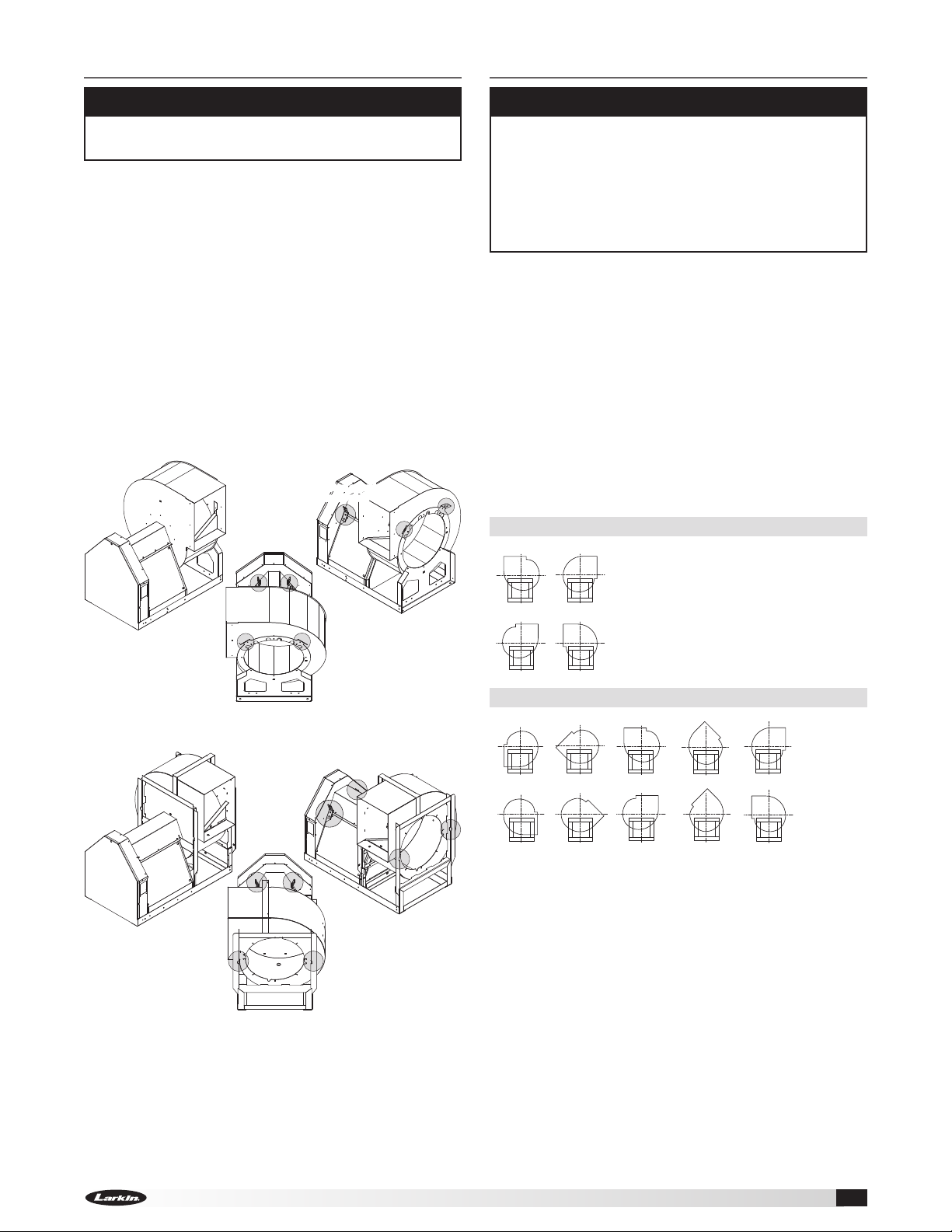
Fans – Rigging and Lifting
Installation
CAUTION
Fans should never be lifted by the shaft, motor,
motor cover or accessories.
Fans are to be rigged and moved by the lifting
brackets provided or by the skid when a forklift is
used. Location of brackets varies by model and size.
Handle in such a manner as to keep from scratching
or chipping the coating. Damaged finish may reduce
ability of fan to resist corrosion. See coating repair
section of this manual for details involving touch-up of
damaged surfaces.
• Use standard lifting and rigging practices.
• ALL lifting brackets on each component must be
utilized at the same time.
• Fan to be kept level during lifting and installation.
Shading indicates lifting point locations
XUEF-200 and XUEF-300
Lifting bracket on opposing side
Lifting bracket on opposing side
(not shown in this view)
(not shown in this view)
CAUTION
When installing a fan, ensure the proper protective
devices are used to protect personnel from
moving parts and other hazards. A complete line
of protective accessories are available from Larkin
including: inlet guards, outlet guards, belt guards,
shaft guards, protective cages and electrical
disconnects.
Move the fan to the desired location. Check and
tighten fasteners throughout the unit and then fasten
securely through mounting holes provided in the base
angles. The unit must be set level (shimming may be
necessary). Flexible duct connections and vibration
isolators should be used where noise is a factor.
The motor voltage and ampere rating must be
checked for compatibility with the electrical supply
prior to final electrical connection. Supply wiring to the
fan must be properly fused, and conform to local and
national electrical codes.
Discharge Positions
XUEF-200
CW UB
CW TH
XUEF-400
CCW UB
XUEF-300 and XUEF-400
CW BH
CCW BH
CCW TH
CW BAU
CCW BAU
CW UB
CCW UB
CW TAU
CCW TAU
CW TH
CCW TH
The discharge is factory set as specified by customer
order, however, certain sizes can be rotated to other
discharge positions in the field if necessary. If rotating
the fan housing, accommodations may need to be
made for the fan to drain properly. The XUEF-200,
all sizes and XUEF-300, sizes 24 and less, have field
rotatable housings. For the XUEF-400, rotatable
housings are standard sizes 30 and less, arrangement
10, and Class 0, I and II. Removal of the housing bolts
allows the discharge to be rotated to the clockwise
positions above. For DB discharge position, a portion
of the frame angle must be removed.
Fan rotation is always specified from the drive side of
the housing.
Utility Fans 5
Page 6
R
o
t
a
t
i
o
n
R
o
t
a
t
i
o
n
R
o
t
a
t
i
o
n
R
o
t
a
t
i
o
n
Turning
Vanes
POOR
POOR
GOOD
Length of Straight Duct
GOOD
One fan
wheel
diameter
One fan
diameter
3/4 to
one fan
wheel
diameter
R
o
t
a
t
i
o
n
R
o
t
a
t
i
o
n
R
o
t
a
t
i
o
n
R
o
t
a
t
i
o
n
Turning
Vanes
POOR
POOR
GOOD
Length of Straight Duct
GOOD
R
o
t
a
t
i
o
n
R
o
t
a
t
i
o
n
R
o
t
a
t
i
o
n
R
o
t
a
t
i
o
n
Turning
Vanes
POOR
POOR
GOOD
Length of Straight Duct
3/4 to one
fan
wheel
diameter
3/4 to one
fan
wheel
diameter
One fan
diameter
3/4 to one
fan
wheel
diameter
R
o
t
a
t
i
o
n
R
o
t
a
t
i
o
n
R
o
t
a
t
i
o
n
Turning
Vanes
POOR
POOR
GOOD
POOR
Length of Straight Duct
GOOD
One fan
wheel
diameter
3/4 to
one fan
wheel
diameter
One fan
diameter
3/4 to
one fan
wheel
diameter
SYSTEM EFFECT FACTORS CURVES
STATIC PRESSURE LOSS
1.2
1.0
0.8
0.6
0.4
0.2
0.0
CURVE 1
CURVE 2
CURVE 3
CURVE 4
Installations with inlet or discharge configurations
R
o
t
a
t
i
o
n
R
o
t
a
t
i
o
n
R
o
t
a
t
i
o
n
R
o
t
a
t
i
o
n
Turning
Vanes
POOR
POOR
GOOD
Length of Straight Duct
GOOD
3/4 to
one fan
wheel
diameter
SYSTEM EFFECT FACTORS CURVES
STATIC PRESSURE LOSS
1.2
1.0
0.8
0.6
0.4
0.2
0.0
CURVE 1
CURVE 2
CURVE 3
CURVE 4
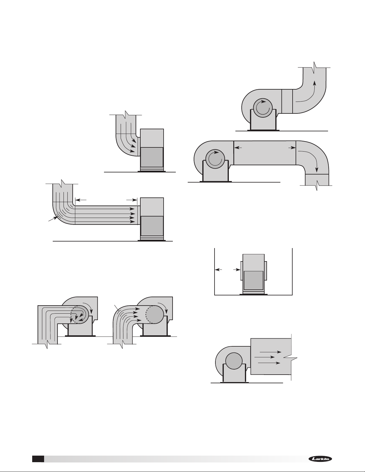
that deviate from this manual may result in reduced
fan performance. Restricted or unstable flow at the
fan inlet can cause pre-rotation of incoming air or
uneven loading of the fan wheel yielding large system
losses and increased sound levels. Free discharge
or turbulent flow in the discharge ductwork will also
result in system effect losses. Refer to the following
diagrams for the most efficient installation conditions.
Ducted Inlet Installations
Inlet Duct Turns - Installation of a duct turn or elbow
too close to the fan inlet
reduces fan performance
because air is loaded
unevenly into the fan
wheel. To achieve full
fan performance, there
should be at least three
fan wheel diameters
between the turn or
elbow and the fan inlet.
POOR
Ducted Outlet Installations
Discharge Duct Turns - Duct turns located near the
fan discharge should always be in the direction of the
fan rotation.
Fan performance is reduced when duct turns
are made immediately off the fan
discharge. To achieve cataloged fan
performance there should be at least
three equivalent
duct diameters of
straight ductwork
between the fan
discharge and
any duct turns.
Three fan wheel diameters
Turning
Vanes
GOOD
Inlet Spin - Inlet spin is a frequent cause of reduced
fan performance. The change in fan performance is a
function of the intensity of spin and not easily defined.
The best solution is proper duct design and airflow
patterns. Turning vanes reduce the effects of inlet
spin.
t
a
t
i
o
n
Turning
Vanes
R
o
POOR
Utility Fans6
GOOD
R
o
t
a
t
Non-Ducted Installations
Inlet Clearance - Installation of a fan with an open
inlet too close to a wall or bulkhead will cause
reduced fan performance. It is desirable to have
a minimum of three-fourths of a wheel diameter
between the fan inlet and the wall.
i
o
n
Free Discharge - Free or abrupt discharge into a
plenum results in a reduction in fan performance. The
effect of discharge static regain is not realized.
3/4 to one
fan
wheel
diameter
Single Fan Installation
Page 7

Fan Drainage Piping and Trap Detail
(TRAP BY OTHERS)
ENERGY RECOVERY
PLENUM
SUBFLOOR
1.25 NPT
.75 NPT
*BASED ON STANDARD
VEKTOR ERS CURB HEIGHTS
*
*
ROOF
CURB
P.O.BOX 410 SCHOFIELD, WISCONSIN 54476-0410
TITLE
DRAWN BY
ECO
B
ENG. REF.
DATE
SUPERSEDES
SCALE
CAD DRAWING NO.
FAUST
06/29/2009
1/8
VK-ERS
N = Negative fan pressure (inches W.C.)
H = N - 0.5 inches minimum
H/2
H/2
H
1.25 inch minimum
N
FAN ON
FAN OFF
14.750
14.000
NOTE: INSULATION OR OTHER MEANS
OF FREEZE PROTECTION MAY BE
REQUIRED IN CERTAIN CLIMATES
(TRAP BY OTHERS)
ERS DRAIN SUBMITTAL
(by others)
Fans may have been supplied with an optional drain.
Drains are located at the underside of the scroll
housing. The drain may need to be connected to a
drainage system to ensure proper disposal of any
water or condensate that may occur.
• Drain connections are 1.0 inch MNPT
• Installed piping to have a downward angle to allow
for drainage
• Fill traps to recommended level before start-up
Note: A conservative method of trap design is to set
N = total static pressure.
Positive Pressure Trap
Connect
this end
to fan drain.
H/2 H/2
H
N
1.25 inch
minimum
N = Negative fan pressure (inches W.C.)
H = N - 0.5 inches minimum
Check local codes for proper disposal of drain water
which has been in contact with the exhaust air.
Fans used for grease exhaust need to be equipped
with a separate grease collector.
FAN ONFAN OFF
Utility Fans 7
Page 8

Installation of UL/cUL 762 Listed
**Per NFP
be a minimum of 40 in.
above the r
MOTOR
FAN
MOTOR
Fans for Restaurant Exhaust
The UL/cUL 762 listing for restaurant exhaust is
available on the XUEF-300 and 400.
UL/cUL 762 fans are listed for a maximum operating
temperature of 375°F
door and 1inch
(191°C)
(25.4mm)
outlet guard is strongly recommended when the fan
discharge is accessible. An upblast discharge is
recommended. The fan discharge must be a minimum
of 40 inches
(1016 mm)
exhaust duct must be fully welded to a distance of
18inches
40 in.**
(1016 mm)
(457mm)
Upblast Discharge
Weatherhood
A 96 the fan discharge must
oof surface.
(1016 mm)
above the roof surface.
and includes an access
drain connection. An
above the roof line and the
XUEF 300 and 400 models are
listed for grease removal (UL/cUL
762) File no. MH11745
Optional Companion
Flange
3 Wheel
Diameters
Duct
from
kitchen
hood
18 in.*
(457 mm)
*Per NFPA 96 the duct
must be of all-welded
construction to a
minimum distance of
18 inches (457 mm)
above the roof surface.
V-Belt Drives
V-Belt Drive Installation
1. Remove the protective coating from the end of the
fan shaft using mineral spirits or another similar
solvent. Check to ensure that the shaft is free of
nicks and burrs.
2. Slide sheaves on shafts. Do not drive
sheaves on as this may result in
bearing damage.
3. Align fan and motor sheaves
with a straight edge or
string and tighten.
4. Place belts over sheaves.
Do not pry or force belts,
as this could result in
damage to the cords in
the belts.
5. Adjust the tension until the belts appear snug. Run
the unit for a few minutes and allow the belts to
“Set” properly.
6. With the fan off and disconnect locked out, adjust
the belt tension by moving the motor pivot plate.
When in operation, the tight side of the belts
should be in a straight line from sheave to sheave
with a slight bow on the slack side.
Aligning Sheaves with
a Straight Edge
This drawing is for dimensional information only. See the latest edition
of NFPA 96 Standard for Ventilation Control and Fire Protection of
Commercial Cooking Operations for detailed installation instructions,
materials, duct connections and clearances.
Alignment of Pulleys and Belts
Check pulleys and belts for proper alignment to avoid
unnecessary belt wear, noise, vibration and power
loss. Motor and drive shafts must be parallel and
pulleys in line as shown in Figure 1.
CORRECT WRONG WRONG WRONG
Figure 1
The adjustable motor pulley is set at the factory for
the fan RPM specified by the customer. Fan RPM can
be increased by closing or decreased by opening the
adjustable motor pulley. Multi groove variable pitch
pulleys must be adjusted an equal number of turns
open or closed. Any increase in fan speed represents
a substantial increase in load on the motor.
To avoid motor overheating and possible burnout,
motor load amperes should always be checked and
compared to nameplate rating when fan speed is
increased.
Utility Fans8
Page 9

R
o
t
a
t
i
o
n
R
o
t
a
t
i
o
n
R
o
ta
t
io
n
R
o
ta
t
io
n
Backward Inclined
Forward Curved
Airflow
Airflow
Backward Inclined Forward Curved
Airflow
These are the original drawings on the Illustrator file
when I opened it. The IOM had the wheel layered on
top of the scroll.
I will incorporate the
wheel on the scroll
without creating
an additional
layer in the
InDesign file.
R
o
t
a
t
i
o
n
Airfoil
Forward Curved
Wheel
Cone
Wheel
Cone
Inlet
Cone
Inlet
Cone
Radial Gap, Overlap and Wheel Alignment
Wheels must rotate freely and not rub on the inlet
cone. ModelXUEF wheels overlap the inlet cone.
Refer to the table for the proper dimension.
Radial Gap and Alignment
Efficient fan performance can be maintained by having
the correct radial gap, overlap and wheel alignment.
These items should be checked after the fan has been
in operation for 24 hours and before start-up when the
unit has been disassembled.
Radial Gap: Adjust inlet cone
position such that the radial gap
between the wheel cone and inlet
cone is evenly distributed around
the wheel.
Radial gap is adjusted by
loosening the inlet cone/ring bolts
and centering the cone/ring on the
wheel. If additional adjustment is
required to maintain a constant
radial gap, loosening the bearing
bolts and centering the wheel is
acceptable as a secondary option.
Overlap: Overlap is adjusted by loosening the wheel
hub from the shaft and moving the wheel to the
desired position along the shaft.
The transition between the inlet cone and wheel
should be as shown; there is a smooth feel to the
profile when moving from one component to the other.
Method for Centering Wheel: On belt drive units,
centering can be accomplished by (a) loosening
the inlet cone bolts to move the inlet cone or by (b)
loosening the bearings in order to move the shaft.
Wheel and inlet cone overlap can be adjusted by
loosening the wheel hub set screws and moving the
wheel to the desired position. Tighten all fasteners
and set screws securely and realign drive pulleys after
adjustment.
Overlap
A
Radial
Gap
Radial
Gap
Straight
Straight
Edge
Edge
Wheel
Inlet
Inlet
Cone
Cone
Cone
Radial Gap and Overlap Dimensions
Overlap
Tolerance
XUEF-200 XUEF-300 XUEF-400
A Overlap
inches (mm)
206 306 - - 207 307 - - 208 308 - - -
15
210 310 4
407 1
408 2
409 3
410 3
212 312 412 4
213 313 413 4
215 315 415 5
216 316 416 5
218 318 418 6
⁄16 (125)3⁄8 (10)
7
⁄16 (37) 215⁄32 (63)1⁄8 (3)
11
⁄16 (68) 17⁄32 (31)1⁄8 (3)
11
⁄16 (94)7⁄32 (6)
11
⁄16 (94)7⁄32 (6)
1
⁄4 (108)
11
⁄16 (119)3⁄8 (10)
3
⁄16 (132)7⁄16 (11)
3
⁄4 (146)7⁄16 (11)
3
⁄8 (162)15⁄32 (12)1⁄8 (3)
220 320 420 7 (178)
13
222 322 422 7
324 424 8
327 427 9
330 430 10
333 433 11
336 436 12
340 440 14
344 444 15
349 449 17
⁄16 (198)17⁄32 (13)3⁄16 (5)
5
⁄8 (219)9⁄16 (14)
7
⁄16 (240)11⁄16 (17)1⁄4 (6)
9
⁄16 (268)11⁄16 (17)3⁄8 (10)
7
⁄16 (291)15⁄16 (24)3⁄8 (10)
3
⁄4 (324)15⁄16 (24)3⁄8 (10)
3
⁄16 (360)29⁄32 (23)3⁄8 (10)
9
⁄16 (395) 11⁄8 (29)3⁄8 (10)
1
⁄8 (435) 11⁄4 (32)1⁄2 (13)
13
⁄16 (478) 117⁄32 (39)1⁄2 (13)
18
15
⁄16 (532) 19⁄16 (40)1⁄2 (13)
20
11
⁄32 (9)
1
⁄2 (13)
1
⁄8 (3)
1
⁄8 (3)
1
⁄8 (3)
1
⁄8 (3)
1
⁄8 (3)
1
⁄8 (3)
1
⁄8 (3)
3
⁄16 (5)
1
⁄4 (6)
227⁄8 (581) 129⁄32 (48)1⁄2 (13)
1
⁄2 (648) 129⁄32 (48)1⁄2 (13)
25
Wheel Rotation
Rotation direction of the wheel is critical and incorrect
rotation will result in reduced air performance,
increased motor loading and possible motor burnout.
Check wheel rotation by momentarily energizing the
unit and noting if rotation is in the same direction as
the airflow at the outlet and conforms to the rotation
decal affixed to the unit.
Wheels as viewed from the drive side:
n
o
i
t
a
t
o
R
Backward Inclined
Airflow
n
o
i
t
a
t
o
R
Airfoil
Airflow
attached to the system for which they were
designed. Without proper system static pressure,
the motor could be overloaded.
Model XUEF units should be operated only when
NOTE
Utility Fans 9
Page 10

Field Coating Touch-Up Procedure
for Scratched Areas
Standard coating and color is Larkin’s RAL 7023
Concrete Grey. The procedure outlines the correct
method for repairing minor scratches in the coating.
TOUCH-UP PAINT REPAIR KIT CONTENTS
• One pint of Kem Kromik primer
- including a technical data sheet
• One pint of industrial enamel
- including a technical data sheet
• Four disposable foam brushes
• One sheet sandpaper
• Repair procedure details
1. Scuff affected area to be repaired using medium
sandpaper (provided) or medium scotch brite pad.
Feather the edges.
2. Clean affected area to be touched up using an
alkaline based cleaner and rinse.
3. Apply Kem Kromik primer using 1 inch foam
brush (provided). Follow technical data sheet
instructions.
4. Allow primer to dry a minimum of 2-1/2 hours
before top coating.
5. Apply topcoat with industrial enamel using 1 inch
foam brush (provided). Follow technical data
sheets instructions. Allow painted units to air-dry
and cure before putting into service. See enclosed
Technical Data sheets for detailed drying and cure
schedules at different temperatures.
To order additional coating repair kits please reference
Larkin’s part number HAZ2597 PNT FIELD REPAIR
KIT, RAL 7023 CONCRETE GREY. Please contact
factory with your fan’s serial number for colors other
than our standard.
Electrical Connections
Before electrical connections are made, the supply
voltage, phase and ampere capacity must be checked
for compatibility with the fan motor. In addition, the
supply wiring must be properly fused and conform
to local and national electrical codes. If the unit is
supplied with a safety disconnect switch, ensure
proper wiring to the fan motor. Be sure the disconnect
is switched to the “OFF” position before connecting
supply wires. If no disconnect is supplied, ensure the
supply wire is not live before connection. Supply wires
are then connected to the optional safety disconnect
switch (if supplied) or motor.
Utility Fans10
Page 11

Unit Start-Up
WARNING
Disconnect and secure to the OFF position all
electrical power to the fan prior to inspection
or servicing. Failure to comply with this safety
precaution could result in serious injury or death.
Visual Inspection of Equipment
The equipment type and arrangement should be
verified as ordered at once when it arrives at the
jobsite. When a discrepancy is found, the local Larkin
Sales Representative must be notified immediately so
that corrective action may be investigated, also verify
electrical conformance to specifications. Unauthorized
alterations and unauthorized backcharges will not be
recognized by Larkin, Industries.
After the unit has been assembled, installed and all
utilities have been hooked up, the unit is now ready
for operation.
Check
Before starting the unit, check the following:
1. Confirm that building supply voltage matches the
voltage for which the unit is wired.
2. Check all piping and wiring penetrations
made by contractors for water tightness. All
penetrations must be made watertight to prevent
water damage to the unit and building.
3. Rotate the fan wheel manually to be sure that it
is free to operate. Remove any dirt or debris that
may have accumulated during installation.
4. Check the fan bearing setscrews for tightness.
5. Check alignment of sheaves and V-belts (See
maintenance section).
6. Inspect all fasteners to ensure that none have
loosened during shipment.
7. Check flex coupling for proper alignment and
connect between motor shaft and fan shaft
(direct drive).
8. Check all guarding to ensure that it is securely
attached and not interfering with rotating parts.
9. Check all electrical connections for proper
attachment.
10. Check housing and ductwork, if accessible,
for obstructions and foreign material that may
damage the fan wheel.
11. Fill drainage piping trap.
Additional Steps for Initial Start-Up
1. Check for proper wheel rotation by momentarily
energizing the fan. Access to view the wheel can
be gained through the blower housing access
panel.
One of the most frequently encountered problems
are motors that are wired to rotate the wheel in
the wrong direction. This is especially true with
3-phase installations where the motor will run in
either direction, depending on how it has been
wired. To reverse rotation of a 3-phase motor,
interchange any two of the three electrical leads.
Single phase motors can be reversed by changing
internal connections as described on the motor
label or wiring diagram.
2. Fans with multi-speed motors should be checked
on low speed during initial start-up.
3. Check for unusual noise, vibration or overheating
of bearings. Refer to the “Troubleshooting” section
of this manual if a problem develops.
4. Grease may be forced out of the bearing seals
during initial start-up. This is a normal self-purging
feature for the type of bearing used on this
product.
Utility Fans 11
Page 12

Vibration
On start-up and during operation, the unit should
operate smoothly with minimal vibration. It is possible
that a higher degree of vibration may be experienced.
Excessive vibration if left unchecked, can cause a
multitude of problems, including structural and/or
component failure.
Common Sources of Vibration
1. Wheel Unbalance
2. Drive Pulley Misalignment
3. Incorrect Belt Tension
4. Bearing Misalignment
5. Mechanical Looseness
6. Faulty Belts
7. Drive Component Unbalance
8. Poor Inlet/Outlet Conditions
9. Foundation Stiffness
manual for corrective actions. If observation cannot
locate the source of vibration, a qualified technician
using vibration analysis equipment should be
consulted. If the problem is wheel unbalance, in-place
balancing can be done through the access panel
located on the side of each fan’s tubular housing.
Any correction weights added to the wheel should be
welded to either the wheel back (single-plane balance)
or to the wheel back and wheel cone (two-plane
balance).
The most common
sources of vibration
are listed.
Many of these
conditions can
be discovered by
careful observation.
Refer to the
troubleshooting
section of this
Routine Maintenance and
Operation
CAUTION
When performing any service to the fan, disconnect
the electrical supply and secure fan impeller.
Once the unit has been put into operation, a
routine maintenance schedule should be set up to
accomplish the following:
1. Lubrication of bearings and motor.
2. Wheel, housing, bolts and set screws on the entire
fan should be checked for tightness.
3. Any dirt accumulation on the wheel or in the
housing should be removed to prevent unbalance
and possible damage.
4. Inspect fan impeller and housing looking for fatigue,
corrosion, or wear.
Fan Operation
All fans should be run every thirty (30) days, or at least
“bumped” every thirty days. It is preferred that each
fan is run as this causes all electrical and mechanical
components to get up to temperature, displacing any
formed condensation, redistributes load on bearings,
and redistributes grease in the bearings (motor and
shaft bearings).
CAUTION
When operating conditions of the fan are to be
changed (speed, pressure, temperature, etc.),
consult manufacturer to determine if the unit can
operate safely at the new condition.
Motors
Motor maintenance is generally limited to cleaning
and lubrication. Cleaning should be limited to exterior
surfaces only. Removing dust and grease buildup
on the motor housing assists proper motor cooling.
Never wash-down motor with high pressure spray.
Greasing of motors is only intended when fittings are
provided. Many fractional motors are permanently
lubricated for life and require no further lubrication.
Motors supplied with grease fittings should be
greased in accordance with the manufacturer’s
recommendations. When motor temperature does not
exceed 104ºF (40ºC), the grease should be replaced
after 2000 hours of running time.
Direct drive systems have extended grease lines to
lubricate the motor without removal of any guarding.
Utility Fans12
Page 13

Belt Drive Maintenance
V-belt drives must be checked on a regular basis
for wear, tension, alignment and dirt accumulation.
Premature or frequent belt failures can be caused by
improper belt tension (either too loose or too tight)
or misaligned sheaves. Abnormally high belt tension
or drive misalignment will cause excessive bearing
loads and may result in failure of the fan and/or motor
bearings. Conversely, loose belts will cause squealing
on start-up, excessive belt flutter, slippage and
overheated sheaves. Either excessively loose or tight
belts may cause fan vibration.
When replacing V-belts on multiple groove drives
all belts should be changed to provide uniform
drive loading. Use a set of matched belts whenever
possible. Do not pry belts on or off the sheave.
Loosen belt tension until belts can be removed by
simply lifting the belts off the sheaves. After replacing
belts, ensure that slack in each belt is on the same
side of the drive. Belt dressing should never be used.
Do not install new belts on worn sheaves. If the
sheaves have grooves worn in them, they must be
replaced before new belts are installed.
The proper tension for operating a V-belt drive is
the lowest tension at which the belts will not slip at
peak load conditions. Belts are adjusted by raising or
lowering the motor
pivot plate. For
Deflection =
Belt Span
64
initial tensioning,
the proper
belt deflection
halfway between
sheave centers is
1/64-inch for each
inch of belt span.
Belt Span
Check belt tension two times during the
first 24hours of operation and periodically
thereafter.
Variable Frequency Drive Operation
For operation with variable frequency drive (VFD),
always check motor amps when adjusting the
operating frequency. Motor may be sized for the
original selected operating speed under 60 Hz.
Bypassing the VFD or increasing the speed from this
original selection, even if less than 60 Hz, may cause
motor to overload or failure. Consult factory with fan
serial number, before increasing the upper limiting
frequency.
Always check the fan rpm when adjusting the
operating frequency. Do not exceed maximum class
fan rpm of the wheel.
Bearing Lubrication Schedule
Shaft bearings are the most critical moving part of a
fan. Therefore, special attention should be given to
keeping the bearings clean and well lubricated. Proper
lubrication provides for reduction in friction and
wear, transmission and dissipation of heat, extended
bearing life and prevention of rust.
In order for a lubricant to fulfill these tasks, the proper
grease applied at regular intervals is required. See the
recommended bearing lubrication schedule below.
If unusual conditions exist (temperatures below 32°F
or above 200°F), moisture or contaminants - more
frequent lubrication is required.
Recommended Bearing Lubrication Schedule
Relubrication Schedule in Months
Standard Grease
Fan
RPM
To 250 12 12 12 12 12
500 12 12 11 10 8
750 12 9 8 7 6
1000 12 7 6 5 4
1250 12 6 5 4 3
1500 12 5 4 3 2
2000 12 3 3 2 1
2500 12 2 2 1 0.5
3000 12 2 1 0.5 0.25
3500 12 1 0.5 0.25 x
4000 12 0.5 0.25 x x
5000 12 0.25 x x x
Number
of Shots
• Lubrication interval is based on 12 hour per day operation
and maximum 160°F housing temperature. For 24 hour
per day operation, the interval should be cut in half.
• Lubricant should be added with the shaft rotating and
until clean grease is seen purging from the bearing.
The lubrication interval may be modified based on the
condition of the purged grease. If bearing is not visible to
observe purged grease, lubricate with number of shots
indicated in chart for bore size.
• For conditions including high temperatures, moisture, dirt
or excessive vibration, consult the factory for a specific
lubrication interval for your application.
• Lubricant should be a high quality lithium complex grease
conforming to NLGI Grade 2. Factory recommends
Mobilux EP-2.
• The use of synthetic lubricants will increase lubrication
intervals by approximately 3 times.
1/2 -1 1
4 8 8 10 16
In addition to lubricating the bearings at specified
intervals, set screws in the bearing collars should be
checked for tightness. A bearing collar which has
loosened will cause premature failure of the fan shaft.
Fasteners attaching the bearings to the drive frame
should also be checked.
Bearing Bore (inches)
1
⁄8 - 11⁄2 15⁄8 - 17⁄8 115⁄16 - 23⁄16 27⁄16 - 3
Utility Fans 13
Page 14

Wheel and Fastener Maintenance
Wheels require very little attention when exhausting
clean air, however, air heavily laden with grease or
dirt will tend to accumulate on the wheel causing
unbalance. Wheels exhausting dirty or grease-laden
air require frequent cleaning to assure smooth and
safe operation.
All fasteners, including set screws in the bearing
collars, should be checked for tightness each time
maintenance checks are performed.
A proper maintenance program will help preserve the
performance and reliability designed into the fan.
Utility Fans14
Page 15

Bearing Replacement
For Arr. 10
The intent of this procedure is to allow a field service
technician to replace bearings with the fan remaining
in place in its intended application. All work can
be conducted by accessing the bearings by either
removing a shaft guard, a weatherhood or working
under a weatherhood. This is dependent on the size
of the unit. This procedure assumes the power source
has been locked out prior to removing guards and
covers, belts and pulleys have been loosened and
removed properly and extended lubrication lines have
been disconnected at the bearing. In some cases,
it may be necessary to remove the fan inlet cone
and wheel if the bearings cannot be removed due to
corrosion or damage. See Radial Gap, Overlap and
Wheel Alignment on page 9 to the realign wheel upon
installation.
Bearing Removal
This procedure assumes proper safety measures have
been taken.
• Read and follow all instructions carefully.
• Disconnect and lock-out power before installation
and maintenance.
• Driven sheaves and belts have already been
removed.
• Shaft black coating can be removed with a solvent
similar to a brake/carburetor cleaner.
1. Scribe a line around the shaft by both bearings
and around the bearing base to the bearing
support or write down the measurement from the
end of the shaft to the bearings. This will help in
repositioning the new bearing and wheel cone
overlap.
2. Follow the bearing manufacturers’ procedures for
removal and installation.
3. Before removing the bearing bolts, make sure the
shaft is supported slightly. Remember to consider
the wheel weight on the shaft.
4. Remove both bearings from the shaft and clean/
remove any burrs using an emery cloth or file.
5. Clean mounting surface of any dirt or grease.
Bearing Installation
1. Before installing, read bearing manufacturers’
procedures. Before putting the new bearings on
the shaft, you may need to break what is called
swivel torque on the bearings (depending on style
of bearing). This is done by holding the bearing
housing securely and being able to move the
inner bearing race around freely.
2. Apply light film of oil on shaft, then gently slide
the new bearings onto the shaft.
Do not hammer bearing onto shaft!
3. Align bearings on shaft with the previous scribe
marks that are on the shaft and lock bearing to
shaft.
4. Put bolts into mounting surface and bearings. Do
not tighten.
5. Remove blocks if shaft is supported.
6. Set bearings on support with the scribed marks
locating the bearings. Make sure bearings are
square and level with the shaft.
7. Tighten bolts and torque bearing bolts, bearing
set screws/locking collars as per bearing
manufacturers’ procedures.
8. Rotate shaft by hand to help allow the bearings to
help set in. Also at this time, listen for any unusual
noises such as wheel rubbing on cone and any
bearing noise.
9. Connect extended lube lines in new bearings if
needed.
10. Reinstall the drive sheaves and belts. Check the
belt alignment.
11. Make sure to reinstall all guards and follow proper
safety measures before starting up the fan.
Utility Fans 15
Page 16

Parts List
Each fan bears a manufacturer’s nameplate with model number and serial number embossed. This information
will assist the local Larkin representative and the factory in providing service and replacement parts. Before
taking any corrective action, make certain unit is not capable of operation during repairs.
CAUTION
A fan manufactured with an explosion resistant
motor does not certify the entire unit to be explosion
proof. Refer to ULListing Mark for the fans
approved usage.
• XUEF-200
• XUEF-300
• XUEF-400
Shaft Pulley
Motor Pulley
Weatherhood
Components
(driven)
(driver)
Belt(s)
Drive Side Bearing
Opposite Drive Side Bearing
Fan Shaft
CAUTION
La présence d’un moteur antidéflagrant sur un
ventilateur ne garantit pas que tout l’appareil est
antidéflagrant. Pour connaître les emplois autorisés
de l’appareil, voir son marquage de conformité UL.
Heat Slinger (XUEF-300)
Rub Ring (XUEF-300)
Shaft Seal (XUEF-300)
Drive Frame Assembly
Motor
Outlet Flange
Outlet Guard
Scroll Housing
Wheel
Grease Container
(XUEF-300)
Grease Fan Brackets
(XUEF-300)
Inlet Cone
Inlet Flange
Inlet Companion
Flange
Inlet Guard
Utility Fans16
Page 17

Troubleshooting
WARNING
Before taking any corrective action, make certain
unit is not capable of operation during repairs.
Problem Cause Corrective Action
Wheel Rubbing Inlet
Excessive Noise
Low CFM
High CFM
Static Pressure Wrong
High Motor Amp Draw
Fan Doesn’t Operate
Overheated Bearing
Excessive Vibration
V-Belt Drive
Bearings
Wheel Unbalance Clean all dirt off wheel. Check wheel balance.
Fan Check wheel for correct rotation.
Duct System Higher pressure than design. Filters need replacement.
Fan Decrease fan speed.
Duct System
Duct system has more
or less restriction than
anticipated
Fan Check rotation of wheel. Reduce fan speed.
Duct System
Electrical Supply
Drive Check for broken belts. Tighten loose pulleys.
Motor
Lubrication Check for excessive or insufficient grease in the bearing.
Mechanical
Belts
System Unbalance
Avant d’entreprendre toute action corrective,
s’assurer que l’appareil ne pourra pas fonctionner
durant les réparations.
Adjust wheel and/or inlet cone.
Tighten wheel hub or bearing collars on shaft.
Tighten sheaves on motor/fan shaft. Adjust belt tension.
Align sheaves properly (see procedure).
Replace worn belts or sheaves.
Replace defective bearing(s). Lubricate bearings.
Tighten collars and fasteners.
Resize ductwork. Access door, filters, dampers not
installed.
Remove obstructions in system. Use correction factor to
adjust for temperature/altitude. Resize ductwork. Clean
filters/coils. Change fan speed.*
Resize ductwork. Check proper operation of isolation and
bypass dampers. Check filters and access doors.
Check fuses/circuit breakers. Check for switches turned
off or disconnected. Check for correct supply voltage.
Assure motor is correct horsepower and not tripping
overload protector.
Replace damaged bearing. Relieve excessive belt tension.
Align bearings. Check for bent shaft.
Adjust tightness of belts. Replacement belts should be a
matched set.
Check alignment of shaft, motor and pulleys. Adjustable
pitch pulleys with motors over 15 hp are especially
prone to unbalance. Check wheel balance, rebalance if
necessary.
AVERTISSEMENT
* AIways check motor amps and compare to nameplate rating. Excessive fan speed may overload the motor
and result in motor failure. Do not exceed the maximum cataloged rpm of the fan.
Utility Fans 17
Page 18

Maintenance Log
Date _______________ Time _______________ AM/PM
Notes: __________________________________________
________________________________________________
________________________________________________
________________________________________________
________________________________________________
Date _______________ Time _______________ AM/PM
Notes: __________________________________________
________________________________________________
________________________________________________
________________________________________________
________________________________________________
Date _______________ Time _______________ AM/PM
Notes: __________________________________________
________________________________________________
________________________________________________
________________________________________________
________________________________________________
Date _______________ Time _______________ AM/PM
Notes: __________________________________________
________________________________________________
________________________________________________
________________________________________________
________________________________________________
Date _______________ Time _______________ AM/PM
Notes: __________________________________________
________________________________________________
________________________________________________
________________________________________________
________________________________________________
Date _______________ Time _______________ AM/PM
Notes: __________________________________________
________________________________________________
________________________________________________
________________________________________________
________________________________________________
Date _______________ Time _______________ AM/PM
Notes: __________________________________________
________________________________________________
________________________________________________
________________________________________________
________________________________________________
Date _______________ Time _______________ AM/PM
Notes: __________________________________________
________________________________________________
________________________________________________
________________________________________________
________________________________________________
Date _______________ Time _______________ AM/PM
Notes: __________________________________________
________________________________________________
________________________________________________
________________________________________________
________________________________________________
Date _______________ Time _______________ AM/PM
Notes: __________________________________________
________________________________________________
________________________________________________
________________________________________________
________________________________________________
Date _______________ Time _______________ AM/PM
Notes: __________________________________________
________________________________________________
________________________________________________
________________________________________________
________________________________________________
Date _______________ Time _______________ AM/PM
Notes: __________________________________________
________________________________________________
________________________________________________
________________________________________________
________________________________________________
Date _______________ Time _______________ AM/PM
Notes: __________________________________________
________________________________________________
________________________________________________
________________________________________________
________________________________________________
Utility Fans18
Date _______________ Time _______________ AM/PM
Notes: __________________________________________
________________________________________________
________________________________________________
________________________________________________
________________________________________________
Page 19

Maintenance Log
Date _______________ Time _______________ AM/PM
Notes: __________________________________________
________________________________________________
________________________________________________
________________________________________________
________________________________________________
Date _______________ Time _______________ AM/PM
Notes: __________________________________________
________________________________________________
________________________________________________
________________________________________________
________________________________________________
Date _______________ Time _______________ AM/PM
Notes: __________________________________________
________________________________________________
________________________________________________
________________________________________________
________________________________________________
Date _______________ Time _______________ AM/PM
Notes: __________________________________________
________________________________________________
________________________________________________
________________________________________________
________________________________________________
Date _______________ Time _______________ AM/PM
Notes: __________________________________________
________________________________________________
________________________________________________
________________________________________________
________________________________________________
Date _______________ Time _______________ AM/PM
Notes: __________________________________________
________________________________________________
________________________________________________
________________________________________________
________________________________________________
Date _______________ Time _______________ AM/PM
Notes: __________________________________________
________________________________________________
________________________________________________
________________________________________________
________________________________________________
Date _______________ Time _______________ AM/PM
Notes: __________________________________________
________________________________________________
________________________________________________
________________________________________________
________________________________________________
Date _______________ Time _______________ AM/PM
Notes: __________________________________________
________________________________________________
________________________________________________
________________________________________________
________________________________________________
Date _______________ Time _______________ AM/PM
Notes: __________________________________________
________________________________________________
________________________________________________
________________________________________________
________________________________________________
Date _______________ Time _______________ AM/PM
Notes: __________________________________________
________________________________________________
________________________________________________
________________________________________________
________________________________________________
Date _______________ Time _______________ AM/PM
Notes: __________________________________________
________________________________________________
________________________________________________
________________________________________________
________________________________________________
Date _______________ Time _______________ AM/PM
Notes: __________________________________________
________________________________________________
________________________________________________
________________________________________________
________________________________________________
Date _______________ Time _______________ AM/PM
Notes: __________________________________________
________________________________________________
________________________________________________
________________________________________________
________________________________________________
Utility Fans 19
Page 20

Larkin Industries, Inc.
114 David Green Rd., Birmingham, AL 35244
Phone: 1.800.322.4036 Fax: 1.205.987.0583
Email: Sales@larkinhoods.com
480081 • XUEF, Rev. 2, February 2015 Copyright 2015 © Larkin Industries, Inc.20
 Loading...