

Page 1
Document 480956
Model XUED
Centrifugal Utility Fan
Installation, Operation and Maintenance Manual
Please read and save these instructions for future reference. Read carefully before attempting to assemble,
install, operate or maintain the product described. Protect yourself and others by observing all safety
information. Failure to comply with instructions could result in personal injury and/or property damage!
General Safety Information
Only qualified personnel should install this fan.
Personnel should have a clear understanding of these
instructions and should be aware of general safety
precautions. Improper installation can result in electric
shock, possible injury due to coming in contact with
moving parts, as well as other potential hazards.
Other considerations may be required if seismic
activity is present. If more information is needed,
contact a licensed professional engineer before
moving forward.
1. Follow all local electrical and safety codes, as
well as the National Electrical Code (NEC) and the
National Fire Protection Agency (NFPA), where
applicable. Follow the Canadian Electric Code
(CEC) in Canada.
2. The rotation of the wheel is critical. It must be free
to rotate without striking or rubbing any stationary
objects.
3. Motor must be securely and adequately grounded.
4. Do not spin fan wheel faster than max cataloged
fan RPM. Adjustments to fan speed significantly
effects motor load. If the fan RPM is changed, the
motor current should be checked to make sure it is
not exceeding the motor nameplate amps.
5. Do not allow the power cable to kink or come in
contact with oil, grease, hot surfaces or chemicals.
Replace cord immediately if damaged.
6. Verify that the power source is compatible with the
equipment.
7. Never open access doors to a duct while the fan is
running.
DANGER
Always disconnect, lock and tag power source
before installing or servicing. Failure to disconnect
power source can result in fire, shock or serious
injury.
CAUTION
When servicing the fan, motor may be hot enough
to cause pain or injury. Allow motor to cool before
servicing.
CAUTION
Precaution should be taken in explosive
atmospheres.
DANGER
Pour écarter les risques d’incendie, de choc
électrique ou de blessure grave, veiller à toujours
débrancher, verrouiller et étiqueter la source de
courant avant l’installation ou l’entretien.
ATTENTION
Lors de toute intervention sur la soufflante, le
moteur peut être suffisamment chaud pour
provoquer une douleur voire une blessure. Laisser le
moteur refroidir avant toute maintenance.
ATTENTION
Faire preuve de précaution dans les atmosphères
explosives.
Centrifugal Utility Fan 1
Page 2

Receiving
Upon receiving the product, check to ensure all
items are accounted for by referencing the delivery
receipt or packing list. Inspect each crate or carton
for shipping damage before accepting delivery. Alert
the carrier of any damage detected. The customer will
make a notation of damage (or shortage of items) on
the delivery receipt and all copies of the bill of lading
which is countersigned by the delivering carrier. If
damaged, immediately contact Larkin Industries, Inc.
Any physical damage to the unit after acceptance is
not the responsibility of Larkin Industries, Inc.
Unpacking
Verify that all required parts and the correct quantity
of each item have been received. If any items are
missing, report shortages to your local representative
to arrange for obtaining missing parts. Sometimes it
is not possible that all items for the unit be shipped
together due to availability of transportation and truck
space. Confirmation of shipment(s) must be limited to
only items on the bill of lading.
Storage
Fans are protected against damage during shipment.
If the unit cannot be installed and operated
immediately, precautions need to be taken to prevent
deterioration of the unit during storage. The user
assumes responsibility of the fan and accessories
while in storage. The manufacturer will not be
responsible for damage during storage. These
suggestions are provided solely as a convenience
to the user.
Indoor -
fans and accessories is indoors, above grade, in a
low humidity atmosphere which is sealed to prevent
the entry of blowing dust, rain or snow. Temperatures
should be evenly maintained between 30° to 110°F
(-1° to 43°C), wide temperature swings may cause
condensation and “sweating” of metal parts. All
accessories must be stored indoors in a clean, dry
atmosphere.
Remove any accumulations of dirt, water, ice, or snow
and wipe dry before moving to indoor storage. To avoid
“sweating” of metal parts allow cold parts to reach
room temperature. To dry parts and packages use a
portable electric heater to remove any moisture build
up. Leave coverings loose to permit air circulation and
to allow for periodic inspection.
The unit should be stored at least 3½ inches
off the floor on wooden blocks covered with moisture
proof paper or polyethylene sheathing. Aisles between
parts and along all walls should be provided to permit
air circulation and space for inspection.
The ideal environment for the storage of
(89 mm)
Outdoor - Fans designed for outdoor applications
may be stored outdoors, if absolutely necessary.
Roads or aisles for portable cranes and hauling
equipment are needed.
The fan should be placed on a level surface to prevent
water from leaking into the fan. The fan should be
elevated on an adequate number of wooden blocks
so it is above water and snow levels and has enough
blocking to prevent it from settling into soft ground.
Locate parts far enough apart to permit air circulation,
sunlight and space for periodic inspection. To
minimize water accumulation, place all fan parts on
blocking supports so rain water will run off.
Do not cover parts with plastic film or tarps as these
cause condensation of moisture from the air passing
through heating and cooling cycles. Fan wheels
should be blocked to prevent spinning caused by
strong winds.
Inspection and Maintenance During Storage
While in storage, inspect fans once per month. Keep a
record of inspection and maintenance performed.
If moisture or dirt accumulations are found on parts,
the source should be located and eliminated. At
each inspection, rotate the wheel by hand ten to
fifteen revolutions to distribute lubricant in motor and
bearings. If paint deterioration begins, consideration
should be given to touch-up or repainting. Fans with
special coatings may require special techniques for
touch-up or repair.
Machined parts coated with rust preventive should be
restored to good condition promptly if signs of rust
occur. Immediately remove the original rust preventive
coating with petroleum solvent and clean with lintfree cloths. Polish any remaining rust from surface
with crocus cloth or fine emery paper and oil. Do not
destroy the continuity of the surfaces. Thoroughly
wipe clean with Tectyl® 506 (Ashland Inc.) or the
equivalent. For hard to reach internal surfaces or for
occasional use, consider using Tectyl® 511M Rust
Preventive, WD-40® or the equivalent.
Removing From Storage
As fans are removed from storage to be installed
in their final location, they should be protected and
maintained in a similar fashion until the fan equipment
goes into operation.
Centrifugal Utility Fan2
Page 3
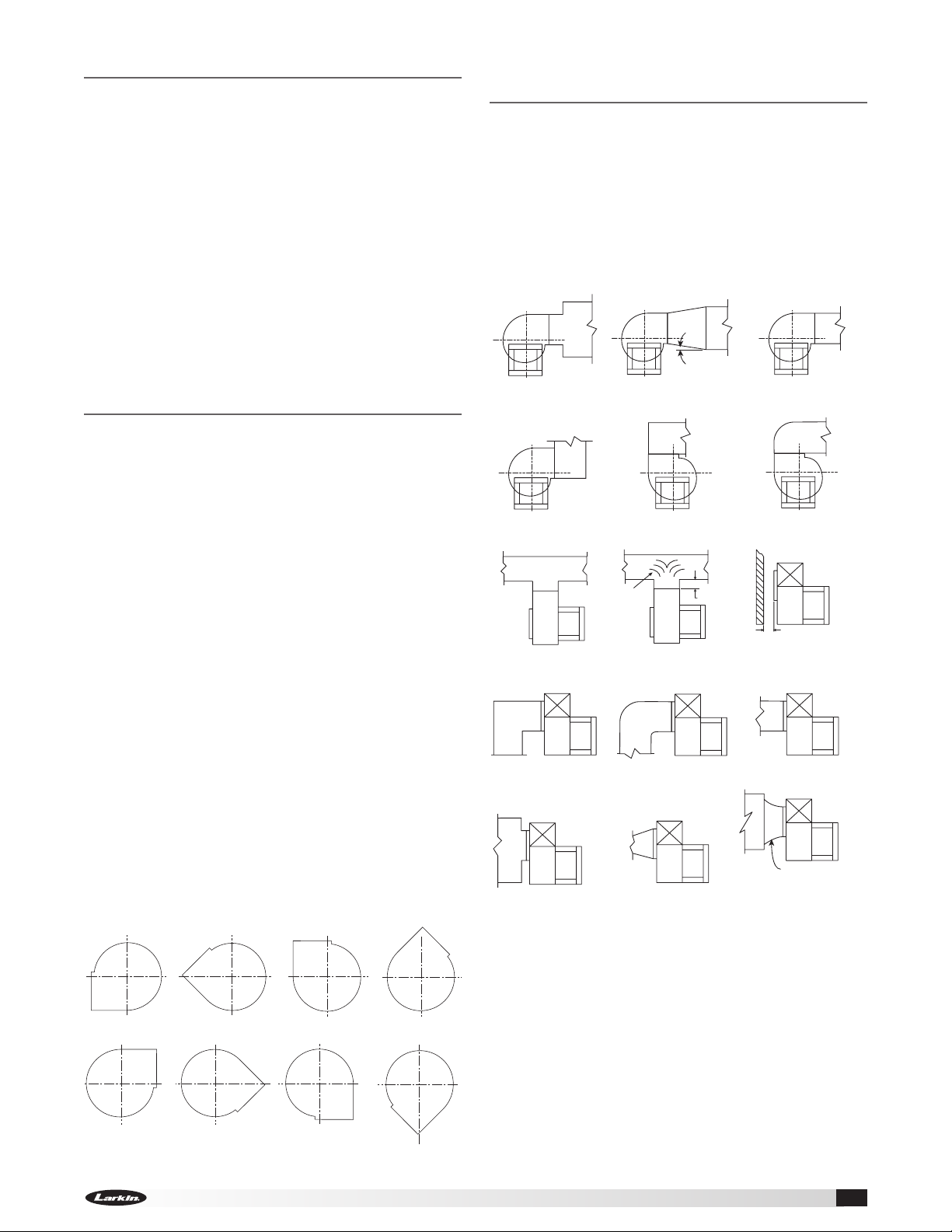
Table of Contents
General Safety Information .................. 1
Receiving, Unpacking, Storage, Inspection ...... 2
Installation
Discharge Positions ....................... 3
Effect of Installation on Performance .......... 3
Pre-Starting Checks
Wheels and Wheel Rotation ................ 4
Mounting for Severe Duty Installation .......... 5
Maintenance
Motor Maintenance ....................... 6
Wheel and Fastener Maintenance ............ 6
Parts List ................................ 6
Troubleshooting ........................... 7
Effect of Installation on
Performance
Restricted or unstable flow at the fan inlet can cause
pre-rotation of incoming air or uneven loading of the
fan wheel, yielding large system losses, increased
sound levels and structural failure of the fan wheel.
Free discharge or turbulent flow in the discharge
ductwork will also result in system effect losses.
These examples show the system layout and inlet
and discharge configurations which can affect fan
performance.
7o MAX.
Installation
Inspect the unit for any damage and report it to
the shipper immediately. Also, check to see that all
accessory items are accounted for.
Move the fan to the desired location and fasten
securely through mounting holes provided in the base
angles. The unit must be set level (shimming may be
necessary). Flexible duct connections and vibration
isolators should be used where noise is a factor.
The motor voltage and ampere rating must be
checked for compatibility with the electrical supply
prior to final electrical connection. Supply wiring to the
fan must be properly fused, and conform to local and
national electrical codes.
The discharge is factory set as specified by customer
order, however, it can be rotated to other discharge
positions in the field if necessary. Removal of the
housing bolts allows the discharge to be rotated to
the clockwise positions below. For TAD, BD and BAD
discharge positions, a portion of the frame angle must
be removed.
Clockwise rotation shown. Counterclockwise
discharge positions are a mirror image of those
shown. Fan rotation is always specified from the drive
side of the housing.
Discharge Positions
POOR
POOR
POOR
POOR
POOR
Turning
Varies
FAIR
POOR
FAIR
FAIR
POOR
One
Impeller
Dia.
GOOD
FAIR
Should be at least
1/2 Impeller Dia.
GOOD
GOOD
Not Greater than
o
60
Including Angle
FAIR
CW BH CW BAU CW TAUCW UB
CW TH CW TAD
CW DB
CW BAD
Centrifugal Utility Fan 3
Page 4

Pre-Starting Checks
R
o
t
a
t
i
o
n
R
o
t
a
t
i
o
n
R
o
ta
t
io
n
R
o
ta
t
io
n
Backward Inclined
Forward Curved
Airflow
Airflow
Backward Inclined Forward Curved
Airflow
These are the original drawings on the Illustrator file
when I opened it. The IOM had the wheel layered on
top of the scroll.
I will incorporate the
wheel on the scroll
without creating
an additional
layer in the
InDesign file.
R
o
t
a
t
i
o
n
R
o
t
a
t
i
o
n
Airflow
Airfoil
Gap
Wheel
Radial
Gap
Overlap
Wheel
DANGER
Always disconnect, lock and tag power source
before installing or servicing. Failure to disconnect
power source can result in fire, shock or serious
injury.
CAUTION
When servicing the fan, motor may be hot enough
to cause pain or injury. Allow motor to cool before
servicing.
CAUTION
Precaution should be taken in explosive
atmospheres.
DANGER
Pour écarter les risques d’incendie, de choc
électrique ou de blessure grave, veiller à toujours
débrancher, verrouiller et étiqueter la source de
courant avant l’installation ou l’entretien.
ATTENTION
Lors de toute intervention sur la soufflante, le moteur
peut être suffisamment chaud pour provoquer
une douleur voire une blessure. Laisser le moteur
refroidir avant toute maintenance.
ATTENTION
Faire preuve de précaution dans les atmosphères
explosives.
Wheels
Wheels must rotate freely and not
rub on the inlet venturi. Model
XUED wheels overlap the inlet
venturi as shown in Figure 2.
Refer to the Approximate Wheel
Clearance Dimensions table for
the proper dimensions for wheel
overlap and radial gap.
Figure 2
Wheel Rotation
Rotation direction of the wheel is critical and incorrect
rotation will result in reduced air performance,
increased motor loading and possible motor burnout.
Check wheel rotation by momentarily energizing the
unit and noting if rotation is in the same direction as
the airflow at the outlet and conforms to the rotation
decal affixed to the unit.
Wheels as viewed from the drive side:
n
o
i
t
a
t
o
R
Backward Inclined
Airflow
Approximate Wheel Clearance Dimensions
Radial
Gap
5
(4)
⁄32
5
(4)
⁄32
5
(4)
⁄32
5
(4)
⁄32
5
(4)
⁄32
5
(4)
⁄32
5
(4)
⁄32
(10)
(10)
(10)
(11)
(13)
(13)
(16)
Overlap
Tolerance
inches (mm)
1
(6)
⁄4
1
(6)
⁄4
1
(6)
⁄4
1
(6)
⁄4
1
(6)
⁄4
1
(6)
⁄4
3
(10)
⁄8
10
13
15
16
18
Overlap
3
7
⁄8
3
8
⁄8
3
⁄8
7
⁄16
1
⁄2
1
⁄2
5
⁄8
Centrifugal Utility Fan4
XUED
Page 5

Mounting for Severe Duty Installation
Isolator Anchoring
Two fasteners per equipment support.
1/2 inch (13 mm) - 13 Bolt
1/2 inch (13 mm) - 13 Bolt
(Four Locations)
(Four Locations)
Isolator Anchoring
Equipment Support Anchoring
One fastener per isolator anchoring.
Four isolators required.
5/8 inch (16 mm) Lag Screw
5/8 inch (16 mm) Lag Screw
Min. 1-1/2 inch (38 mm) Thread Engagement
Min. 1-1/2 inch (38 mm) Thread Engagement
(Two per Equipment Support)
(Two per Equipment Support)
18 Ga. Galvanized G90
with Wood Nailer
Three Supports Required
for Sizes 20 and larger
Equipment Support Anchoring
Min. 5 inch
(127 mm)
3/8 inch (10 mm) S.S. Hilti Kwik Bolt
3/8 inch (10 mm) S.S. Hilti Kwik Bolt
Three Expansion Anchors
Three Expansion Anchors
Min. 2-1/2 inch (64 mm) Engagement
Min. 2-1/2 inch (64 mm) Engagement
2000 Min. PSI
Concrete
Concrete
Deck Anchoring
5/16 inch (8 mm) Self-D rilling Screw
Min. 1/2 inch (13 mm) of Threads Through
Steel
Deck Anchoring
Roof Truss
1/8 inch (3 mm) Thick
or 12 Gauge Min.
Wood Timber
Min. 4 inch (102 mm)
Min. G = 0.42
Timber Anchoring
7/16 inch (11 mm) Lag Bolt
Min. 3-1/4 inch (83 mm) Thread Engagement
Centrifugal Utility Fan 5
Page 6

Maintenance
Parts List
Motor Maintenance
Motor maintenance is generally limited to cleaning
and lubrication (where applicable). Cleaning should be
limited to exterior surfaces only. Removing dust and
grease buildup on the motor housing assures proper
motor cooling. Use caution and do not allow water
or solvents to enter the motor or bearings. Under no
circumstances should motors or bearings be sprayed
with steam, water or solvents.
Many fractional horsepower motors are permanently
lubricated for life and require no further lubrication.
Motors supplied with grease fittings should be
greased in accordance with the manufacturer’s
recommendations.
Wheel and Fastener Maintenance
Wheels require very little attention when exhausting
clean air, however, wheels exhausting dirty air
require frequent cleaning to assure smooth and safe
operation.
All fasteners, including set screws in the bearing
collars, should be checked for tightness each time
maintenance checks are performed.
A proper maintenance program will help preserve the
performance and reliability designed into the fan.
Each fan bears a manufacturer’s nameplate with
model number and serial number embossed. This
information will assist Larkin Industries, Inc. and the
factory in providing service and replacement parts.
Before taking any corrective action, make certain unit
is not capable of operation during repairs.
1
6
5
4
3
2
Available Replacement Parts
1. Scroll housing
2. Drive frame - base angle
3. Intake support panel
4. Wheel (specify rotation)
5. Drive frame assembly
6. Motor
Centrifugal Utility Fan6
Page 7

Troubleshooting
WARNING
Before taking any corrective action, make certain
unit is not capable of operation during repairs.
PROBLEM CAUSE CORRECTIVE ACTION
Excessive
Noise
Low CFM
High CFM
Static
Pressure
Wrong
High
Horsepower
Fan Doesn’t
Operate
* Always check motor amps and compare to nameplate rating. Excessive fan speed may overload the motor
and result in burnout.
Wheel Rubbing Inlet
Wheel Unbalance
Fan Check wheel for correct rotation. Increase fan speed.*
Duct System See page 3.
Fan Resize ductwork. Access door, filters, grills not installed.
Duct System
Duct system has more
or less restriction than
anticipated
Fan Check rotation of wheel. Reduce fan speed.
Duct System
Electrical Supply
Adjust wheel and/or inlet cone. Tighten wheel hub or bearing collars on
shaft.
Clean all dirt off wheel. Check wheel balance, rebalance in place if
necessary.
Change obstructions in system. Use correction factor to adjust for
temperature/altitude. Resize ductwork. Clean filters/coils. Change fan
speed.*
Check rotation of wheel. Adjust fan speed.
Resize ductwork. Check proper operation of face and bypass dampers.
Check filters and access doors.
Check fuses/circuit breakers. Check for switches off. Check for correct
supply voltage.
Avant d’entreprendre toute action corrective,
s’assurer que l’appareil ne pourra pas fonctionner
durant les réparations.
AVERTISSEMENT
Centrifugal Utility Fan 7
Page 8

Larkin Industries, Inc.
114 David Green Rd., Birmingham, AL 35244
Phone: 1.800.322.4036 Fax: 1.205.987.0583
Email: Sales@larkinhoods.com
480956 • XUED, Rev. 9, February 2015 Copyright 2015 © Larkin Industries, Inc.8
 Loading...