

Page 1
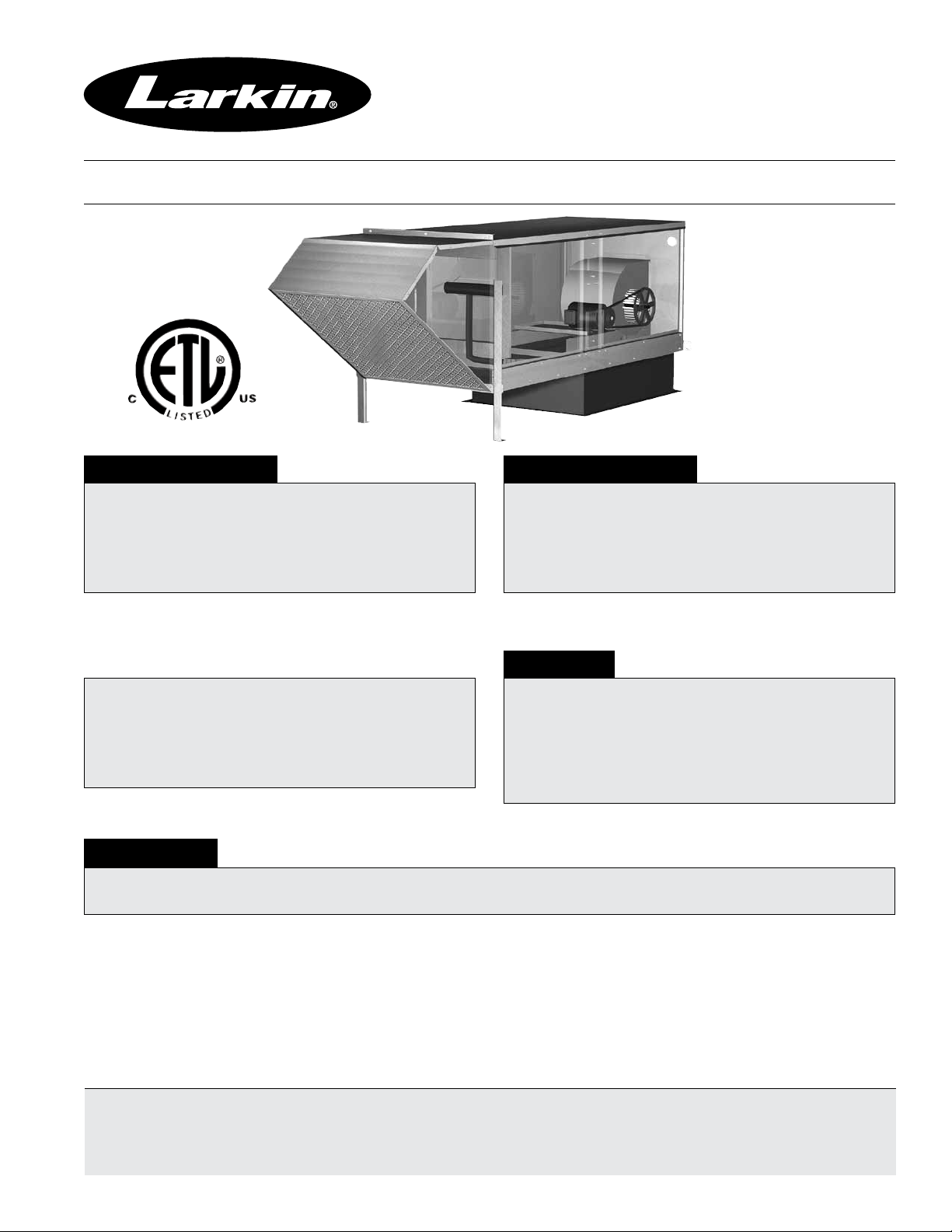
Make-Up Air Unit
Installation, Operation, and Maintenance Manual
Part # 474614
Model XDGK
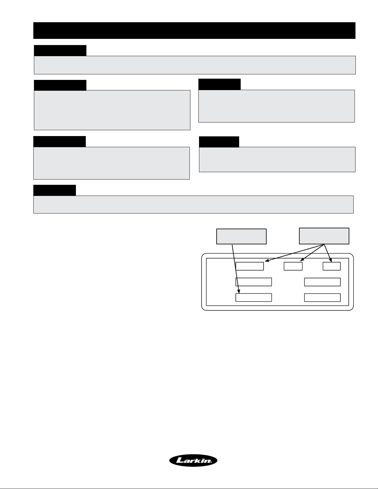
FOR YOUR SAFETY
If you smell gas
1. Open windows
2. Don’t touch electrical switches
3. Extinguish any open flames
4. Immediately call your gas supplier
FOR YOUR SAFETY
The use and storage of gasoline or other
flammable vapors and liquids in open
containers in the vicinity of this appliance is
hazardous.
WARNING!
Disconnect all electrical power to the fan and
secure to the “OFF” position prior to inspection
or servicing. Failure to comply with this safety
precaution could result in serious injury or death.
Improper installation, adjustment, alteration,
service or maintenance can cause property
damage, injury or death. Read the installation,
operating, and maintenance instructions
thoroughly before installing or servicing this
equipment.
IMPORTANT!
All factory provided lifting lugs must be used when lifting any unit. Failure to comply with this safety
precaution could result in property damage, serious injury or death.
Report any damaged equipment to the shipper immediately!
All units are shipped on a skid or packaged to minimize damage during shipment. The transporting carrier
has the responsibility of delivering all items in their original condition as received from Larkin. The individual
receiving the equipment is responsible for inspecting the unit for obvious or hidden damage, recording any
damage on the bill of lading before acceptance and filing a claim (if required) with the final carrier. Some
accessory items are stored inside the unit during shipping. Care must be taken during installation to prevent
damage to units.
Please read and save these instructions for future reference. Read carefully before attempting to assemble, install, operate
or maintain the unit. Failure to comply with instruction could result in personal injury and/or property damage!
Upon receiving unit, check for any damage that may have occurred during transit and report it immediately to the shipper.
Also check to see that all accessory items are accounted for.
December 2008
Page 2
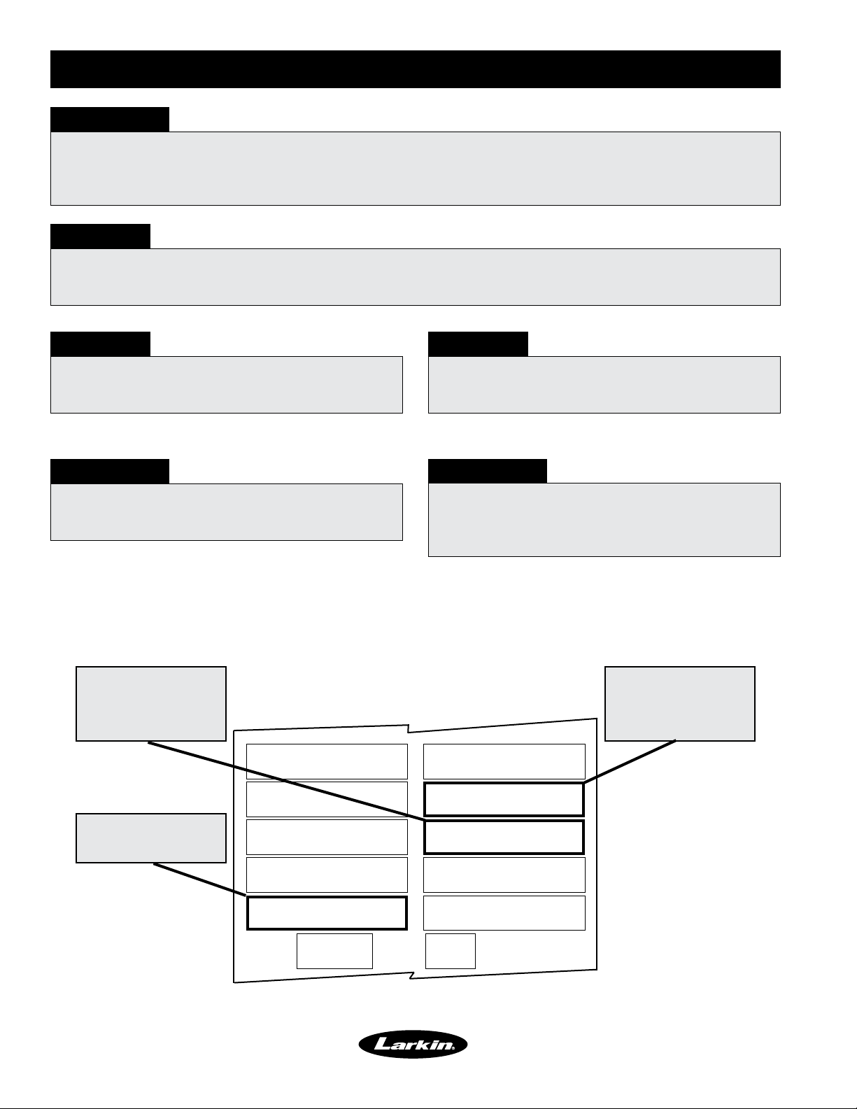
Table of Contents
Installation
Clearances to Combustibles &
Services Clearances.................. 2
Unit — Arrangement DB/HZ .............. 3
Hinged Weatherhood — XDGK-H25........ 4
Electrical Wiring........................ 5
Direct Gas Piping .....................6-7
Maintenance
Routine............................19-20
Fall ................................. 20
Start-up Check List .................... 21
Maintenance Log...................... 21
Reference
Start-Up
Blower ..............................8-9
Direct Gas .........................10-13
Gas Train Layout XDGK-H15 - <400 MBH .. 22
Control Center Layout XDGK-H15 ........ 22
Gas Train Layout XDGK-H25 <800MBH.... 23
Control Center Layout XDGK-H25 ........ 23
Troubleshooting
Blower .............................. 14
Heater, General ....................... 14
Heater, XDGK-H15 .................... 15
Heater, XDGK-H25 ..................16-17
Excessive Noise or Vibration ............ 18
STORAGE
When a unit is not going to be in service for an extended period of time, certain procedures should be followed
to keep the unit in proper operating condition:
• Plug all piping
• Rotate fan wheel monthly.
• Energize fan motor once every three months
• Store belts flat to keep them from warping and stretching
• Store unit in location without vibration
• Cover unit with tarp to protect from dirt and moisture
NOTE!
Do not cover unit with a black tarp, this would
promote condensation.
NOTE!
Improper storage which results in damage to the
unit will void the warranty.
Clearance to Combustibles / Service Clearances
Floor Top Sides Ends
Insulated Units 0 inches (0 mm) 0 inches (0 mm) 0 inches (0 mm) 0 inches (0 mm)
Clearance to combustibles is defined as the minimum distance required between the heater and adjacent combustible
surfaces to ensure the adjacent surface’s temperature does not exceed 90 degrees above the ambient temperature.
Recommended Minimum Service Clearances
Housing 32 and less 42 inches (1066.8 mm) on the controls side of the unit
Clearances for component removal may be greater than the service clearances listed.
2
Page 3
Installation - Arrangement DB / HZ
SUPPLY
DUCT
B
23 in.
(584 mm)
A
23 in.
(584 mm)
27.5 in.
(699 mm)
Curb Length Actual
27.5 in.
(699 mm)
Curb
Width
Actual
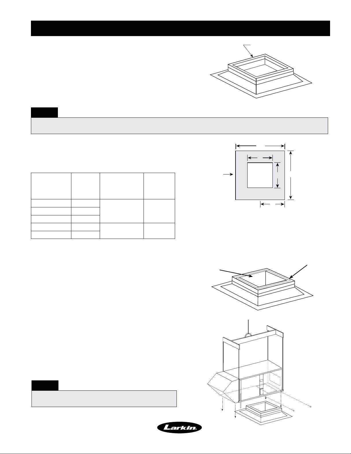
Recommended Roof Opening
(center in curb)
Center Supply Duct
in Roof Opening
Airflow
D
Step 1 Install Curb or Equipment Support(s)
Roof Curb
Position curb/equipment support(s) on the roof (reference
the CAPS submittal for placement of curb/equipment
support(s) in relation to the unit). Verify that unit supports
are level, shim if necessary. Attach curb to roof and flash
into place. Attach the equipment support(s) to the roof,
remove metal cover, flash to wooden nailer and reinstall
cover. Refer to roof curb detail.
NOTE!
Roof Curb Detail
The use of a duct adapter is recommended on a downblast (DB) arrangement to align the ductwork with the
supply unit. The duct adapter is only a guide and is not to be used as support for the ductwork.
Step 2 Install Ductwork
Good duct practices should be followed for all ductwork. All
ductwork should be installed in accordance with SMACNA
and AMCA guidelines, NFPA 96 and all local codes.
Supply
Model
Duct Size
(A x B)
Curb to Center
Supply Duct (C)
XDGK-109-H15 13 x 14
XDGK-112-H15 16 x 18
XDGK-115-H25 18 x 22
XDGK-118-H25 22 x 24
All dimensions shown are in inches.
Distance from
right side of
14½ 27½ x 27½XDGK-110-H15 14 x 16
20 45½ x 45½
Curb
Dimension
Actual
(D x E)
Step 3 Apply Sealant
Apply an appropriate sealant around the perimeter
of the curb to isolate fan vibration and prevent water
penetration.
Airflow
Note: Roof openings can be as large as the curb size minus
3-1/2 in. or as small as the duct size plus 1/2 in.
Supply Duct width (B) is centered over Curb width (E).
Supply Length (A) may not be centered over Curb Length (D).
Roof Opening Details
Supply Air Ductwork
(Arrangement DB only)
A
SUPPLY
DUCT
E
B
C
Sealant
Step 4 Install Unit
Use a crane and a set of spreader bars hooked to the
factory lifting lugs to lift and center the unit on the
curb/equipment support(s). Prior to disconnecting from
crane, adjust support legs on the intake of the unit.
Use self-tapping sheet metal screws to fasten the unit
to the curb/equipment support(s).
NOTE!
The use of all lifting lugs and a set of spreader bars
is mandatory when lifting the unit.
Ductwork and Sealant Application
Placement of Unit
3
Page 4
Installation - Hinged Weatherhood
Tools Required:
• 5/6-inch nut runner
• Caulk gun with weatherproof sealant
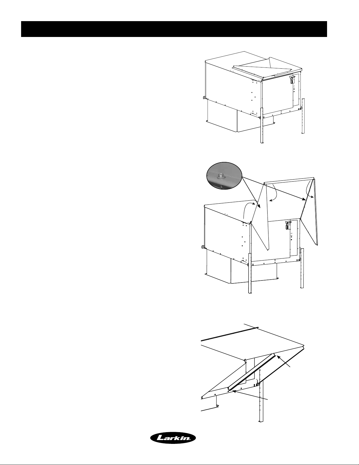
The XDGK-H25 weatherhood is folded-up and shipped
on top of the unit. To install:
Step 1 Rotate sides up on weatherhood
a. Run two sheet metal screws where shown to hold
side in rotated position. Pilot holes are provided.
b. Rotate opposite side up on weatherhood and
repeat step 1A.
Step 2 Rotate assembly forward
Step 3 Fasten weatherhood sides to the
unit
Screw the sides of the weatherhood to the unit. Pilot
holes are provided.
Step 4 Caulk Seams
Caulk all seams with an appropriate weatherproof
sealant.
Step 5 Install filter tracks
Install the two center filter tracks which were shipped
inside the unit.
a. Slide the tabbed end of each track into the slot
at the bottom of the intake opening on the unit
housing.
b. Rotate the tracks up to the top outer edge of the
weatherhood such that the weatherhood edge
slides into the slot in the tracks.
Step 6 Insert filters
Insert the factory provided aluminum mesh intake
filter(s) into the track located in the face of the
weatherhood. Filters slide in from the top. Be sure
the filters are properly orientated (an airflow direction
arrow is located on the side of the filters). Insert the
retaining screws on the sides of the weatherhood,
three (3) per side, to keep the filters in place.
Rotate sides up, install screws.
Rotate Assembly forward.
See Step 3.
Center filter track.
(2 pieces)
Slot in unit.
4
Page 5
Installation - Electrical Wiring
IMPORTANT!
Before connecting power to the unit, read and understand the following instructions and wiring diagrams.
Complete wiring diagrams are attached to the inside of the control center door(s).
IMPORTANT!
All wiring should be done in accordance with the
latest edition of the National Electrical Code ANSI/
NFPA-70 and any local codes that may apply. In
Canada, wiring should be done in accordance with
the Canadian Electrical Code.
IMPORTANT!
The equipment must be properly grounded.
Any wiring running through the unit in the airstream
must be protected by metal conduit, metal clad
cable or raceways.
CAUTION!
If replacement wire is required, it must have a
temperature rating of at least 105ºC, except for
energy cut-off or sensor lead wire which must be
rated to 150ºC.
DANGER!
High voltage electrical input is needed for this
equipment. This work should be performed by a
qualified electrician.
CAUTION!
Any wiring deviations may result in personal injury or property damage. Larkin is not responsible for any
damage to, or failure of the unit caused by incorrect final wiring.
Step 1 Determine the Size of the Main
Power Lines
The unit nameplate states the voltage and the unit’s
total MCA. The main power lines to the unit should be
sized accordingly. The nameplate is located on the
outside of the unit on the control panel side.
Unit’s MCA
VOLTS HZ PH
Voltage, Hertz,
and Phase
Step 2 Provide the Opening(s) for the
Electrical Connections
Electrical openings vary by unit size and arrangement
and are field supplied.
SUP HP
MCA
Electrical Nameplate
EXH HP
MOP
Step 3 Connect the Main Power
Connect the main power lines to the disconnect switch and main grounding lug(s). Torque field connections
to 20 in-lbs. See the control center layout in the reference section for main disconnect and grounding lug(s)
locations.
5
Page 6
Installation - Direct Gas Piping
IMPORTANT!
All gas piping must be installed in accordance with the latest edition of the National Fuel Gas Code ANSI/
Z223.1 and any local codes that may apply. In Canada, the equipment shall be installed in accordance with the
Installation Code for Gas Burning Appliances and Equipment (CGA B149) and Provincial Regulations for the
class. Authorities having jurisdiction should be consulted before installations are made.
WARNING!
All components of this or any other gas fired heating unit must be leak tested prior to placing the unit into
operation. A soap and water solution should be used to perform this test. NEVER test for gas leaks with an
open flame.
WARNING!
If pressure testing in excess of 1/2 psig
(3.5 kPa), the heater and manual shutoff valve must
be disconnected from the supply gas line.
IMPORTANT!
All piping should be clean and free of any foreign
matter. Foreign material entering the gas train can
damage the valves, regulators and burner.
WARNING!
If pressure testing at or below 1/2 psig (3.5 kPa),
the heater must be isolated from the supply gas line
by closing its manual shutoff valve.
IMPORTANT!
Do NOT connect the unit to gas types other than
what is specified and do NOT connect the unit to
gas pressures that are outside of the pressure range
shown on the label.
Step 1 Determine the Supply Gas Requirements
The unit’s direct gas nameplate states the requirements for the gas being supplied to the unit. The direct gas
nameplate is located on the outside of the unit on the control center side.
Maximum gas
pressure
Minimum gas
pressure for
maximum output
Type of Gas
MAX BTU/HR
BTU/H MAX
NORMAL MANIFOLD
PRESSURE
PRESSION DÕADMISSION
NORMALE
MIN GAS
PRESSURE
PRESSION DE GAZ
MIN BURNER
PRESSURE DROP
PERTE MIN DE PRESSION
DANS LE BRULEUR
TYPE OF GAS
NATURE DU GAZ
EQUIPPED FOR
CONCU POUR
AGAINST
SCFM “ W.C.
CONTE
“ W.C.
“ W.C.
“ W.C.
MIN BTU/HR
BTU/H MIN
MIN GAS PRESSURE
FOR MAX OUTPUT
PRESSION DE GAZ MIN
POUR PUISSANCE MAX
MAX GAS
PRESSURE
PRESSION DE GAZ
MAX
MAX BURNER
PRESSURE DROP
PERTE MAX DE PRESSION
DANS LE BRULEUR
DESIGN DT
DT NORMALE
EXTERNAL STATIC PRESSURE
PRESSION STATIQUE EXTERIEURE
“ W.C.
“ W.C.
PSI
F
Direct Gas Nameplate
6
Page 7
Installation - Direct Gas Piping
Step 2 Install Additional Regulator if
Required
When the supply gas pressure exceeds the maximum
gas pressure shown on the direct gas nameplate, an
additional regulator (by others) is required to reduce
the pressure. The regulator must have a listed leak
limiting device or it must be vented to the outdoors.
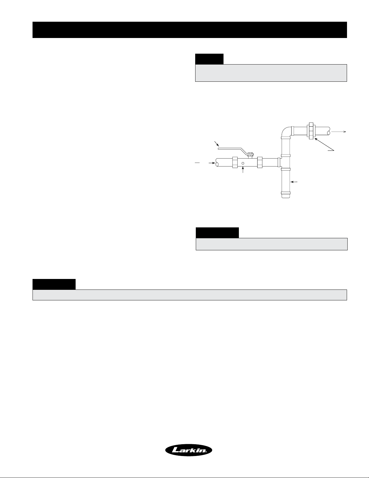
Step 3 Connect the Supply Gas Line
A manual shut off valve (gas cock), 1/8 in. (3.175 mm)
plugged test port and 6 in. (152.4 mm) drip leg must
be installed prior to the gas train. The valve and the
test port must be accessible for the connection of a
test gauge. Supply gas connections must be made by
a qualified installer and are not furnished by Larkin.
This assembly must be installed in the inlet of the gas
train. When installed, the manual shut off valve (gas
cock) will be outside of the unit and will shutoff all gas
to the unit.
NOTE!
The regulator located inside the unit is used to
adjust the unit’s maximum output temperature.
Gas Cock
Ground Joint Union
From
Gas
Supply
1/8 in. Plugged Tap
6 in. Trap
Supply Gas Line
To
Controls
Step 4 Test the System for Leaks
Check both the supply lines and the factory piping for
leaks. Apply a soap and water solution to all piping
WARNING!
NEVER test for a gas leak with an open flame.
and watch for bubbling which indicates a leak.
WARNING!
The factory piping has been checked for leaks, but should be rechecked due to shipping and installation.
7
Page 8
Start-Up - Blower
Pre-Start-Up Check
Rotate the fan wheel by hand and make sure no
parts are rubbing. Check the V-belt drive for proper
alignment and tension (a guide for proper belt tension
and alignment is provided in the belt maintenance
section). Check fasteners, set screws and locking
collars on the fan, bearings, drive, motor base and
accessories for tightness. Remove any shipping
fasteners from the blower vibration isolators.
WARNING!
Check the housing, blower, weatherhood, and ductwork for foreign objects and debris before the blower is run.
SPECIAL EQUIPMENT REQUIRED
Below is a list of special tools that are required. A recommended model is shown, but equivalent
products may be used.
Description Manufacturer-Model Phone Website
Voltage Meter Fluke-177 1-800-44-FLUKE www.fluke.com
Amperage Meter Fluke-177 1-800-44-FLUKE www.fluke.com
Thermometer Fluke-50 1-800-44-FLUKE www.fluke.com
Micro Amp Meter Fluke-116 1-800-44-FLUKE www.fluke.com
U-Tube manometer Dwyer-Slack Tube 1-219-897-8000 www.dwyer-inst.com
Tachometer Monarch-Pocket Tach 100 1-800-999-3390 www.monarchinstrument.com
WARNING!
Disconnect and lock-out all power and gas before
performing any maintenance or service to the unit.
Failure to due so could result in serious injury or
death and damage to equipment.
Step 1 Check the Voltage
Before starting the unit, compare the supplied voltage, hertz, and phase with the unit and motor’s nameplate
information. The nameplate is located on the outside of the unit on the control panel side.
VOLTS HZ PH
EXH HP
MOP
Voltage, Hertz,
and Phase
SUP HP
MCA
Electrical Nameplate
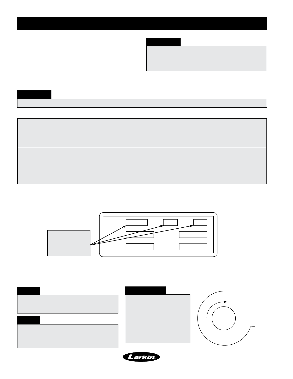
Step 2 Check the Blower Rotation
Open the blower access door and run the blower momentarily to determine the rotation. Arrows are placed on
the blower scroll to indicate the proper direction.
NOTE!
To reverse the rotation on three phase
units, disconnect and lock-out the power,
then interchange any two power leads.
NOTE!
To reverse the rotation on single phase
units, disconnect and lock-out the
power, then rewire the motor per the
manufacturer’s instructions.
IMPORTANT!
If the blower is rotating
in the wrong direction,
the unit will move some
air, but will not perform
as designed. Be sure to
perform a visual inspection
to guarantee the correct
blower rotation.
Rotation
Blower
Housing
Blower Rotation
8
Page 9

Start-Up - Blower
Step 3 Check for Vibration
Check for unusual noise, vibration or overheating of the bearings. Reference the troubleshooting section for
corrective actions.
IMPORTANT!
Excessive vibration may be experienced during
the initial start-up. Left unchecked, it can cause a
multitude of problems including structural and/or
component failure.
IMPORTANT!
Generally, fan vibration and noise is transmitted
to other parts of the building by the ductwork. To
minimize this undesirable effect, the use of heavy
canvas duct connectors is recommended.
Step 4 Motor Check
Measure the motor’s voltage, amps and RPM’s and compare to the specifications on the motor’s nameplate.
Check the overload setting and make sure it matches the motor’s amperage rating. If the motor’s actual amps
are greater than the nameplate amps, check and correct the supply voltage or air volume of the blower.
Step 5 Air Volume Measurement and
Check
Measure the unit’s air volume (CFM) and compare it
with its rated air volume. If the air volume is off, adjust
the fan’s RPM’s by changing/adjusting the drive.
NOTE!
The most accurate way to measure the air volume is
by using a pitot traverse method downstream of the
blower. Other methods can be used but should be
proven and accurate.
IMPORTANT!
Changing the air volume can significantly increase the motor’s amps. If the air volume is changed, the motor’s
amps must be checked to prevent overloading the motor.
NOTE!
To ensure accuracy, be sure the dampers are open when checking the air volume.
Step 6 Set-up Heating Inlet Air Sensor
The heating inlet air sensor will automatically turn the heat on if the outdoor air temperature is below the set
point while the fan is operating.
• Typical setting: 55-65ºF. (12.8-18.3ºC)
9
Page 10

Start-Up - Direct Gas
IMPORTANT!
For proper unit function and safety, follow the startup procedure in the exact order that it is presented.
IMPORTANT!
This start-up should begin after all of the installation
procedures and the Blower start-up have been
completed.
Step 1 Check the Supply Gas Pressure
Check the supply gas pressure and compare it with the unit’s nameplate pressure requirements. Adjust the
supply regulator as needed until the supply gas pressure is within the specified range. The nameplate is located
on the outside of the unit on the control panel side.
Minimum and
maximum gas
pressures for
maximum output
Type of gas
MAX BTU/HR
BTU/H MAX
NORMAL MANIFOLD
PRESSURE
PRESSION DÕADMISSION
NORMALE
MIN GAS
PRESSURE
PRESSION DE GAZ
MIN BURNER
PRESSURE DROP
PERTE MIN DE PRESSION
DANS LE BRULEUR
TYPE OF GAS
NATURE DU GAZ
EQUIPPED FOR
CONCU POUR
MIN BTU/HR
BTU/H MIN
MIN GAS PRESSURE
FOR MAX OUTPUT
“ W.C.
PRESSION DE GAZ MIN
POUR PUISSANCE MAX
MAX GAS
PRESSURE
“ W.C.
PRESSION DE GAZ
MAX
MAX BURNER
PRESSURE DROP
“ W.C.
PERTE MAX DE PRESSION
DANS LE BRULEUR
DESIGN DT
DT NORMALE
AGAINST
SCFM “ W.C.
CONTE
“ W.C.
“ W.C.
PSI
F
EXTERNAL STATIC PRESSURE
PRESSION STATIQUE EXTERIEURE
Direct Gas Nameplate
10
Page 11

9
8
Start-Up - Direct Gas
IMPORTANT!
Proper air velocity over the burner is critical on direct fired gas units. If the air velocity is not within the unit
specifications, the unit will not operate efficiently, may have sporadic shutdowns and may produce excessive
carbon monoxide (CO) or other gases.
Step 2 Set the Burner Air Pressure
Differential
With all filters, the blower access door in place, and
the fan running and discharging 70º F (21.1ºC) air,
connect a U-Tube manometer (inside the unit control
center) upstream and downstream of the burner baffle
(see bottom of page). Measure the static pressure
across the burner.
The proper static pressure should be between 0.625
and 0.675 inches wc (155.68 and 168.14 Pa) If needed,
evenly adjust the baffles above and below the burner,
keeping the burner centered in the opening until the
required pressure is obtained. (Refer to drawing at
right).
NOTE!
The pressure drop was set at the factory and may
not need adjustment.
Adjustable
Top Baffle
Airflow
Burner
Adjustable
Bottom Baffle
IMPORTANT!
This process may need to be repeated until the
proper pressure is achieved. This adjustment
will change the air quantity delivered by the unit
and therefore the air quantity delivered should be
rechecked. Refer to the blower start-up section.
CONTACTOR
ACCESS PANEL
AIRFLOW TAP
MODULATING
VALVE
BURNER MANUAL
SHUTOFF VALVE
COMBINATION
SHUT-OFF
VALVE/REGULATOR
GAS CONNECTION
AIRFLOW SWITCH
BURNER
VIEWPORT
AIRFLOW TAP
Burner and Baffles
NOTE!
To increase the static pressure decrease the
opening. To decrease the static pressure increase
the opening.
TRANSFORMER
7
IGNITION CONTROL
AMPLIFIER
HIGH LIMIT
INLET AIR SENSOR
0.625 - 0.675 in. wc
6
Unit Control Center
11
Page 12

Start-Up - Direct Gas
Step 3 Set the Low Fire Time Delay –
XDGK-H25 only
Check the pilot
gas pressure. The
recommended gas
pressure is 3inches wc.
Adjust the pilot gas
regulator as needed.
The location of the pilot
regulator adjustment is
shown on the pilot valve/
regulator diagram below.
Rotate the adjustment
screw CW to increase the pilot flame and rotate the
screw CCW to decrease the pilot flame.
Step 4 Set the Low Fire Time Delay
Set the low fire time delay to 75% of its maximum
setting. See Maxitrol Series 14 picture below for the
location of the time delay setting.
Step 5 Set the Maximum Firing Rate
Monitor the unit’s actual temperature rise by placing
a thermocouple in the unit’s inlet and a second in the
discharge, three duct diameters downstream of the
burner.
Send the unit to maximum fire by disconnecting and
isolating the wire connected to Terminal 4 on the
Maxitrol amplifier shown.
While monitoring the units temperature rise, set the
maximum firing rate by adjusting the Combination
Valve or Regulator for respective housing sizes
(shown below) until the designed temperature rise
is achieved. After setting the maximum firing rate,
reconnect the wire to the amplifier.
Low fire time
delay setting
(75% of maximum)
Pilot Regulator
adjustment screw
XDGK-H25
Pilot Valve/Regulator
Remove the wire from
terminal #4 to send the
unit to maximum fire
MAX BTU/HR
BTU/H MAX
NORMAL MANIFOLD
PRESSURE
PRESSION DÕADMISSION
NORMALE
MIN GAS
PRESSURE
PRESSION DE GAZ
MIN BURNER
PRESSURE DROP
PERTE MIN DE PRESSION
DANS LE BRULEUR
TYPE OF GAS
NATURE DU GAZ
EQUIPPED
FOR
CONCU POUR
SCFM
AGAINST
CONTE
“ W.C.
“ W.C.
“ W.C.
MIN BTU/HR
BTU/H MIN
MIN GAS PRESSURE
FOR MAX OUTPUT
PRESSION DE GAZ MIN
POUR PUISSANCE MAX
MAX GAS
PRESSURE
PRESSION DE GAZ
MAX
MAX BURNER
PRESSURE DROP
PERTE MAX DE PRESSION
DANS LE BRULEUR
DESIGN DT
DT NORMALE
EXTERNAL STATIC PRESSURE
“ W.C.
PRESSION STATIQUE EXTERIEURE
“ W.C.
“ W.C.
PSI
F
Direct Gas Nameplate
WARNING!
Do not set the burner maximum firing rate based on gas
pressure. It should be set based on the unit’s designed
temperature rise shown on the direct gas label.
NOTE!
The low fire time delay must be set high enough to
provide at least 15 seconds of low fire while the unit
tries to light.
IMPORTANT!
Setting the maximum firing rate during mild weather
conditions may cause the high limit to trip out during
extreme conditions requiring manual resetting.
Maximum firing
rate adjustment
Maxitrol Series 14
NOTE!
The minimum setting for the maximum firing rate
may be higher than required. This is acceptable, the
burner will modulate as needed.
12
XDGK-H15
Combination Valve
XDGK-H25 Regulator
NOTE!
Clockwise rotation increases the temperature
rise, counterclockwise rotation decreases the
temperature rise.
Page 13

Start-Up - Direct Gas
Step 6 Set the Minimum Firing Rate
Disconnect and isolate one of the wires running to the modulating valve to send the unit to its minimum firing
rate. Set the minimum firing rate by adjusting the needle valve shown in picture below.
After setting the minimum firing rate, reconnect the wire to the modulating valve.
IMPORTANT!
The proper minimum firing rate setting results in a
small ribbon of continuous flame which covers the
flame rod and runs across the entire burner.
IMPORTANT!
Do not allow the disconnected wire to come in
contact with a potential ground, damage to the
amplifier or transformer could result.
NOTE!
Counterclockwise rotation increases the minimum
fire rate setting, clockwise rotation decreases the
setting.
NOTE!
Adjusting the maximum and minimum fire may require
the inlet air sensor to be initially set higher than
desired in order to start the burner. Once high and
low fire have been set, the inlet air sensor should be
turned down to the desired temperature.
Step 7 Set the Unit’s Discharge
Temperature
Set the discharge temperature that will provide the
desired space temperature.
IMPORTANT!
The minimum firing rate setting is critical. If the
settings is too high, the unit may not light, too low
and the flame rod may not detect the flame.
Remove one wire to
send the unit to the
minimum firing rate.
Minimum firing
rate adjustment
Modulating Valve
Set the discharge temperature
(65ºF (18.3ºC) Typical)
Maxitrol Series 14 Discharge Temperature Control
IMPORTANT!
The Maxitrol Series 14 should be set to the desired
discharge temperature. The temperature selector is
built into the amplifier.
Step 8 Flame Signal Check
To measure the flame signal connect a micro amp
meter to terminals (FC+) and (FC-) on the Fenwal
flame safeguard. The flame signal should be above 1.0
micro amp and steady.
Check the flame signal with the burner at minimum
fire, mid-fire and high-fire.
NOTE!
If the flame signal is not above 1.0 micro amp and
steady, consult the troubleshooting section.
XDGK-H15 Flame Safeguard
Terminals FC+ and FC-
XDGK-H25 Flame Safeguard
FC+
FC-
13
Page 14

Troubleshooting
Blower Does Not Operate
24 VAC on the secondary of the
main transformer (TR1)
(measure across A1-A2 on
supply blower contactor)
Yes
Supply starter (ST1) energized?
Yes
No
No
Check Main Voltage
(See Blower Start-Up)
Main Disconnect (DS1) Off
(Turn Main Disconnect DS1 On)
Main Transformer (TR1) Defective
(Replace Transformer TR1)
Supply Fan Overload (ST1 OL) Tripped
(Reset and check motor amps, reference Blower Start-Up)
One or more legs of 3 phase is out
(Restore missing legs)
Supply Starter Defective
Thermal overload on motor tripped
Broken Fan Belt
(Replace - Reference V-Belt maintenance in Maintenance section)
Defective motor or capacitor
(Repair/Replace)
Internal motor overload tripped (optional)
(Check motor amps, reference Blower Start-Up)
Note: At this time the supply contactor (ST1) should pull in passing
power to the supply motor and the blower should start.
Heater Does Not Operate
Does not attempt to light (No visible spark)
Is power passing through the
heating inlet air sensor (TS1)?
Yes
Is power passing through the
high limit (HLC1)?
Yes
Is power passing through the
airflow switch (PS2)?
Yes
No
No
No
Heating Inlet Air Senor (TS1) Holding
(Adjust TS1 setting -- Reference Blower Start-Up)
High Limit (HLC1) Tripped
(Reset/Replace High Limit HLC1)
(Check on cause of control loss)
Airflow Switch (PS2) Holding for Proper Airflow
(Correct airflow across burner)
(Reference Direct Gas Start-Up)
At this time the heater should attempt to light
14
Page 15

Troubleshooting
Heater Does Not Operate — XDGK-H15
Attempts to light but no flame (Visible spark)
Is the low fire set properly
(Direct Gas Start-Up)
Yes
Check inlet gas pressure.
(Direct Gas Start-Up)
Gas pressure between the
minimum and maximum shown
on the direct gas label?
Yes
Air in the gas line?
No
Check burner pressure drop
(Direct Gas Start-Up)
No
Adjust the low fire setting
(Reference Direct Gas Start-Up section)
No
Correct gas pressure
(Reference Direct Gas Start-Up section)
Yes
Purge gas line
Pressure drop across the burner
between 0.625 and 0.675 in. wc?
(155.68 and 168.14 Pa)
Yes
Proper spark?
Yes
No
No
Adjust burner baffles
(Reference Direct Gas Start-Up section)
Crossed flame and spark wires
(Uncross wires and reconnect)
Incorrect spark plug gap
(Set spark plug gap to 0.062 in.)
Defective spark plug
(Replace spark plug)
With proper airflow, gas pressure and spark,
the unit should light.
If problems remain, consult the factory
15
Page 16

Troubleshooting
Heater Does Not Operate — XDGK-H25
Attempts to light but no visible pilot. Visible spark.
Check inlet gas pressure.
(Direct Gas Start-Up)
Yes
Note: The minimum and maximum gas pressures
for your unit are shown on the direct gas label.
Gas pressure between the
minimum and maximum shown
on the direct gas label?
Yes
Air in the gas line?
No
Check for proper airflow
(Direct Gas Start-Up)
Yes
Pressure drop across the burner
between 0.625 and 0.675 in. wc?
Yes
Proper spark?
Yes
No
Yes
No
No
Correct gas pressure
(Reference Direct Gas Start-Up Step #1)
Purge gas line
(Verify gas at the pilot, reference Direct Gas Start-Up Step #3)
Note: The airflow may satisfy the airflow switch, but may
make lighting the pilot difficult. Adjust the pressure drop
across the burner to between 0.625 and 0.675 inches wc as
shown in Direct Gas Start-Up Step #2
Adjust burner baffles
(Reference Direct Gas Start-Up Step #2)
Crossed flame and spark wires
(Uncross wires and reconnect)
Incorrect spark plug gap
(Set spark plug gap to 0.062 inches)
Defective spark plug
(Replace spark plug)
Check for proper pilot pressure.
(Direct Gas Start-Up)
No
Pilot pressure correct?
Yes
16
Note: A high pilot pressure will make lighting more difficult. Lower
the pilot pressure in increments until the unit lights. Then set the
pilot per the instruction in Direct Gas Start-Up Step #3)
No
Adjust the pilot pressure
(Reference Direct Gas Start-Up section)
With proper airflow, gas pressure and spark,
the unit should light.
If problems remain, consult the factory.
Page 17

Troubleshooting
Heater Does Not Operate — XDGK-H25
Visible pilot.
Measure the flame signal when
there is a visible pilot.
Note: The flame signal should be steady and above 1.0 micro amp
with a visible pilot.
Reference Direct Gas Start-Up section.
Flame signal greater than
1.0 micro amp?
Yes
Check for proper airflow
(Direct Gas Start-Up)
Pressure drop across the burner
between 0.625 and 0.675 in. wc?
Yes
Check the minimum firing rate?
(Direct Gas Start-Up)
Is the minimum firing
rate set correctly?
Yes
No
No
No
Unit is not grounded
(Properly ground unit)
Flame rod is grounding out
(Adjust the flame rod to avoid contact with the burner or the unit)
Cracked porcelain on flame rod
(Replace flame rod)
Note: When the pressure is low or marginal and the unit begins
heating, the air density will change. This can cause the pressure to
drop below the minimum setting. Also, low airflow can cause the
flame to walk out of the burner and away from the flame sensor,
causing the unit to recycle.
Adjust burner baffles
(Reference Direct Gas Start-Up Step #2)
Adjust the minimum firing rate
(Reference Direct Gas Start-Up Step #6)
Does the flame signal
remain constant?
Yes
No
If the signal slowly drops off, typically the airflow is too low
(Reference Blower Start-Up Step #5)
If it suddenly drops to zero, the flame rod is grounding out
(Adjust the flame rod to avoid contact with the burner or the unit)
If the flame signal is above 1.0 micro amp and constant,
the main gas valves will remain open until the call for
heat is interrupted, or the unit is shut down.
17
Page 18

Troubleshooting
Excessive Noise or Vibration
Belts worn or loose?
No
Sheaves aligned?
Yes
Wheel unbalanced? Clean and/or balance wheel.
No
Bearings worn? Replace worn bearings.
No
Wheel rubbing on inlet? Adjust wheel or inlet.
Yes
(Reference V-Belt Drive maintenance in the Maintenance section)
No
(Reference V-Belt Drive maintenance in the Maintenance section)
Yes
Yes
Yes
Replace worn belts or tighten loose belts.
Align sheaves
18
No
Note: At this time noise and vibration should be at acceptable levels.
Page 19

Maintenance - Routine
FANFAN
MOTOR
MOTOR
CAUTION!
Lock-out the gas and the electrical power to the unit before performing any maintenance or service operations
to this unit.
V-Belt Drives
V-belt drives must be checked on a regular basis for
wear, tension, alignment and dirt accumulation.
Check the tension by measuring the deflection in the
belt as shown below.
Check the alignment by using a straight edge across
both sheaves as shown below.
IMPORTANT!
Do not pry belts on or off the
sheave. Loosen belt tension until
belts can be removed by simply
lifting the belts off the sheaves.
Deflection =
IMPORTANT!
When replacing V-belts on
multiple groove drives all belts
should be changed to provide
uniform drive loading.
Belt Span
64
IMPORTANT!
Premature or frequent belt failures can be caused
by improper belt tension, or misaligned sheaves.
Abnormally high belt tension
or drive misalignment will
cause excessive bearing
loads and may result in
failure of the fan and/or
motor bearings.
Abnormally low belt tension
will cause squealing on
start-up, excessive belt
flutter, slippage and
overheated sheaves
IMPORTANT!
Do not install new belts on worn
sheaves. If the sheaves have
grooves worn in them, they must
be replaced before new belts are
installed.
Motors
Motor maintenance is generally limited to cleaning
and lubrication (where applicable).
Cleaning should be limited to exterior surfaces only.
Removing dust and grease build-up on the motor
assures proper motor cooling.
Motors supplied with grease fittings should be
greased in accordance with the manufacturer’s
recommendations.
Belt Span
Belt Tension Drive Alignment
IMPORTANT!
Do not allow water or solvents to enter the motor
or bearings. Motors and bearings should never be
sprayed with steam, water or solvents.
IMPORTANT!
Greasing motors is only intended when fittings are
provided. Many motors are permanently lubricated,
requiring no additional lubrication.
19
Page 20

Maintenance - Routine
Wheels
Wheels require little attention when moving clean air. Occasionally oil and dust may accumulate on the wheel
causing imbalance. When this occurs the wheel and housing should be cleaned to assure proper operation.
Filters
Filter maintenance is generally limited to cleaning and
replacement.
The aluminum mesh filters can be washed in warm
soapy water.
IMPORTANT!
When reinstalling filters be sure to install them
with the airflow in the correct direction. An airflow
direction arrow is located on the side of the filters.
IMPORTANT!
An adhesive spray can be added to aluminum mesh
filters to increase their efficiency.
Greasing motors is only intended when fittings are
provided. Many motors are permanently lubricated,
requiring no additional lubrication.
Maintenance - Fall
Start-Up
Repeat the Blower Start-Up procedure #4 and Direct Gas Start-Up procedure #1 and #2. This will ensure that
the gas and air are set properly before the heating season begins, and should lead to trouble free operation all
winter.
High Limit
The high limit switch may have tripped over the summer, it should be checked and reset if necessary.
Burner
Inspect the burner for accumulation of scales on both the upstream and downstream sides of the mixing plates.
Any scaling or foreign material should be removed with a wire brush.
Visually check that all holes in the mixing plates are clear.
If any burner ports are plugged (even partially), clear
them with a piece of wire or another appropriate tool.
Replace or tighten any loose or missing fasteners on the
mixing plates. Always use zinc plated or stainless steel
fasteners.
Inspect and clean the flame and spark rod. Occasional
replacement of the flame rod and spark rod may be
necessary to ensure optimum unit performance.
WARNING!
Do not enlarge burner ports when clearing a
blockage, performance could be affected.
NOTE!
Flame rods can last many years, but because of
thermal expansion of the porcelain, flame rods can
fail over time.
Gas Train
Test the system for leaks by checking both the supply lines and factory piping for leaks. Apply a soap and water
solution to all piping; watch for bubbling which indicates a leak.
20
Page 21

Start-Up Checklist
Unit Model Number ____________________________ (e.g. XDGK-109-H15)
Unit Serial Number ____________________________ (e.g. 04C99999 or 10111000)
Start-up date ____________________________ (MM/DD/YYYY)
Start-up Personnel Name ____________________________
Start-up Company ____________________________
Phone Number ____________________________
Pre Start-Up Checklist - check boxes as items are completed
o Check tightness of all factory wiring connections
o Hand-rotate blower to verify free rotation
o Verify supply voltage to the main disconnect
o Verify the supply gas pressure
Start-Up Blower Checklist - refer to IOM for further detail
o Check line voltage L1-L2 _________________ L2-L3 _______________ L1-L3 _______________
o Check blower rotation
o Check for vibration
o Supply fan RPM _____________ RPM
o Motor nameplate amps _____________ Amps
o Actual motor amps _____________ Amps
o Actual CFM delivered _____________ CFM
Component
o Heating inlet air sensor _____________ Actual Setting (Typical Setting 55-65º F
(12.8-18.3ºC))
Start-Up Direct Gas - refer to IOM for further detail
o Check supply gas pressure ___________ Maximum __________ Minimum __________ Actual
o Set pilot gas pressure (XDGK-H25 only) ______________ Actual Setting (Pilot gas pressure is 3 in. wc.)
o Set burner pressure differential ______________ Actual Setting (Typical 0.65 in. wc.)
o Set the maximum firing rate ______________ temp rise
o Set the minimum firing rate ______________ check
o Set the unit’s operating temperature ______________ degrees F
Maintenance Log
Date Time Notes
21
Page 22

Reference
Typical XDGK-H15 Gas Train Layout less than 400 MBH and Control Center Layout
5
GROUNDING LUG
6
CONTACTOR
ACCESS PANEL
TO BURNER, SPARK
ROD, AND FLAME ROD
AIRFLOW TAP
MODULATING
VALV E
8
TRANSFORMER
2
IGNITION CONTROL
4
BURNER MANUAL
SHUTOFF VALV E
COMBINATION
SHUT- OFF
VALVE/REGULATOR
GAS CONNECTION
AIRFLOW SWITCH
BURNER
VIEWPORT
AIRFLOW TAP
7
AMPLIFIER
3
HIGH LIMIT
1
INLET AIR SENSOR
NOTE!
This is a typical gas train. The gas train in your unit may be different.
1. Heating Inlet Air Sensor - Ductstat that automatically energizes burner when inlet air temperature falls
below set point.
2. Ignition Control - Monitors flame, shuts down unit when unsafe conditions are detected.
3. High Limit - Prevents unit from discharging air above a set point.
4. Main Disconnect - On/Off switch, provides single point power connection to unit.
5. Grounding Lugs - Completes electrical circuit
6. Motor Starter - 24 Volt magnetic contacts for starting motor, 3 phase motors have electronic overload.
7. Amplifier - Controls modulating valve, assures the desired temperature is delivered.
8. Control Transformer - Provides 24 volts for controls.
22
Page 23

Reference
Typical DGK-H25 Gas Train Layout - Less than 800 MBH
DGK-H25 Control Center Layout
Typical XDGK-H25 Gas Train Layout less than 800 MBH
Modulating Valve
Pilot Connection to Burner
Burner Manual Shut-Off Valve
Safety Shut-Off Valves
Typical XDGK-H25 Control Center Layout
9
10
Regulator
Pilot Test Port
4
7
Pilot Valve/Regulator
Supply Gas Pressure Test Port
Pilot Manual Shut-Off Valve
2
3
1
Gas Connection
11
1. Control Board - Provides mounting for the
controls.
2. Supply Motor Starter - 24 volt magnetic
contacts for starting supply motor.
3. Supply Overload - Provides electronic
overload protection to supply motor.
4. Low Voltage Transformer - 75 VA
transformer that provides low voltage to fan/
starter controls and optional inlet damper.
5. Air Proving Switch - Monitors the airflow to
ensure proper combustion.
6. Purge Timer - Initiates 10 second prepurge
before lighting the burner.
7. Low Voltage Transformer - 75 VA
transformer that provides low voltage to the
heat controls.
8
6
5
8. Inlet Air Sensor - Outdoor air stat that
automatically controls the heating based on
outdoor air temperature.
9. Flame Safeguard/Spark Generator Monitors flame, shuts down unit when unsafe
conditions are detected.
10. Amplifier - Controls modulating valve,
assures the desired temperature is delivered.
11. Heat Relay - Allows amplifier to modulate the
modulating gas valve.
12. High Limit (not pictured) - disc shaped
component located in the upper right hand
corner of the control center. Prevents the unit
from discharging air above a fixed set point of
120ºF.
23
Page 24

WARRANTY
Manufacturer warrants this equipment to be free from defects in
material and workmanship for a period of one year from the date of
shipment. Any units or parts which prove to be defective during the
warranty period will be replaced at our option when returned to our
factory, transportation prepaid. Motors are warranted by the motor
manufacturer for a period of one year. Should motors furnished by
Manufacturer prove defective during this period, they should be
returned to the nearest authorized motor service station. Larkin will
not be responsible for any removal or installation costs.
As a result of our commitment to continuous improvement, Larkin
reserves the right to change specifications without notice.
Larkin Industries, Inc.
114 David Green Rd., Birmingham, AL 35244
Phone: 1.800.322.4036 Fax: 1.205.987.0583
www.larkinhoods.com
IOM XDGK Rev. 2 December 2008
Copyright © 2008 Larkin
 Loading...