

Page 1
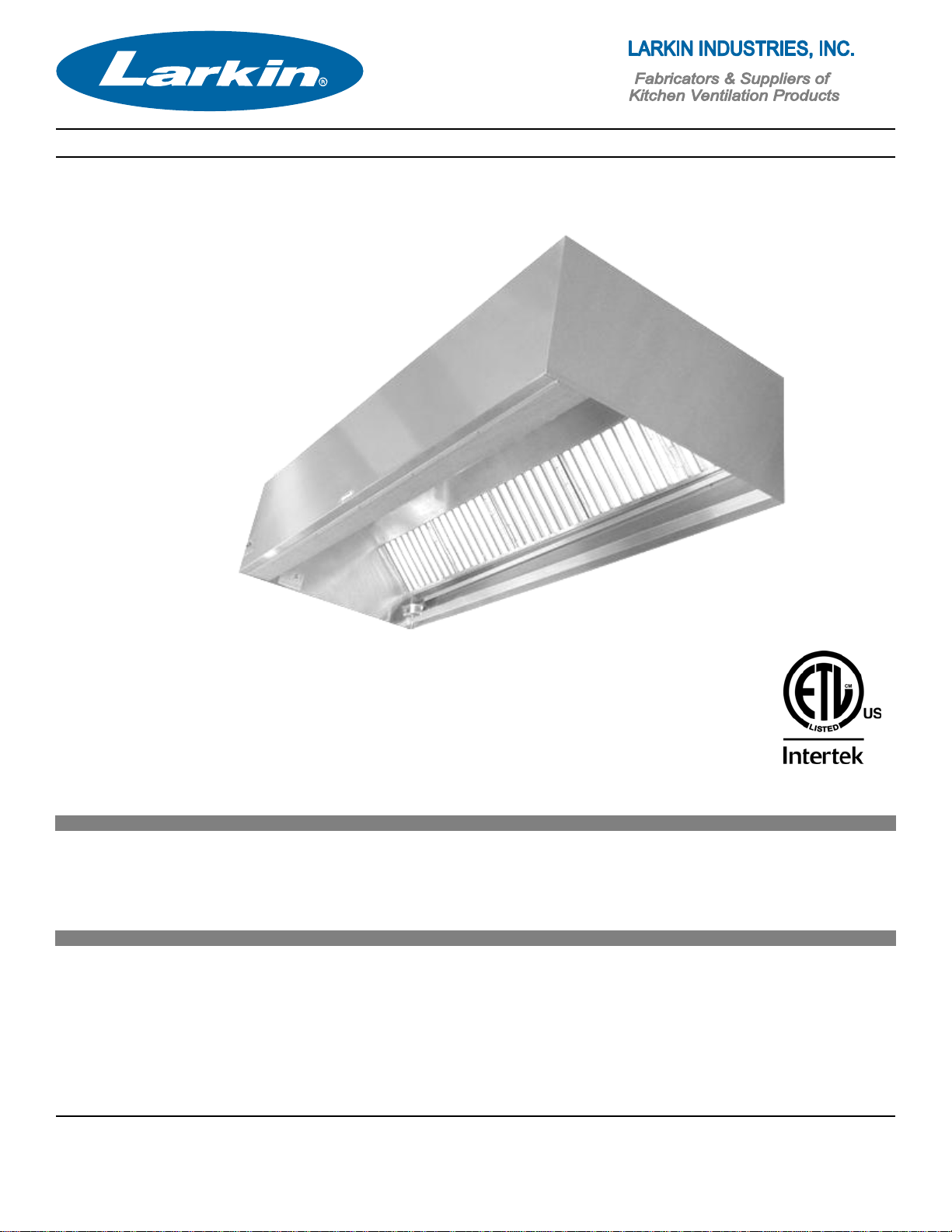
Commercial Kitchen Hood
Installation and Maintenance Manual
Receiving Shipments
Upon receiving unit, check for any interior or exterior damage, if found, report it to the carrier
immediately. Check that all accessory items are accounted for and damage free.
Caution!
We strongly suggest hood Installation should only be performed by a qualified and licensed
mechanical contractor who is familiar with the level of involvement for proper installation. Insure
proper safety precautions are taken, permits are obtained, and code requirements are met.
Save these instructions. This document is the property of the owner of this equipment and is
required for future maintenance. Leave this document with owner after installation or service has
been completed.
2012
Page 2

Table of Contents
Hood Installation..……………………………………………………………………….1
Basic Hanging Methods…………………...…….………..……………………………2
End-to-End Hoods….……………………………………………………………….…..3
Back-to-Back Hoods….……………………………………………………………….. 4
Grease Trough and Cup Installation………………………………………………….5
Back Return Plenum……………………………………………………………………6
Front Supply Plenum…………………………………………………………………...7
Splash Panels…………………………………………………………………………...8
Ceiling Enclosures………………………………………………………………………9
End Curtains……………………………………………………………………………..9
Duct Work………………………………………………………………………………10
Wiring……………………………………………………………………………………11
Maintenance……………………………………………………………………………12
Warranty………………………………………………………………………………..13
Trouble Shooting………………………………………………………………………14
Page 3

Hood Installation Instructions
When uncrating, handling, or installing, the
installer should exercise extreme caution to
protect the stainless steel surfaces from
damage, as they are costly to repair.
The installing contractor for the Kitchen
Ventilation System is responsible for verifying
field measurements of the constructed kitchen
area. Consult project plans when determining
exact location of the hood(s). Determine how
the hood will be hung and prepare the
structural support system using inserts,
shields, angle iron, etc., and ½” threaded rod
with turn buckles (hanging material by others).
Verify that the materials used are sufficient to
support the weight of hood and hanging
system. (Refer to NFPA-96 for proper
installation methods and materials.)
All Larkin Industries, Inc. hoods are provided
with hanging brackets on top of hood, ½”
threaded rod should be used with necessary
nuts, washers, etc (see fig. 1). Turnbuckles
are recommended for leveling (see fig. 2).
Recommended mounting height from bottom
edge of hood to the finished floor is 6’-6”, (18”
-24” from bottom edge of filter to cooking
surface for Back Shelf type models). Hoods
should be hung level, and where possible, the
exhaust outlet should be in line with the
exhaust fan opening. Duct runs, offsets,
elbows, etc. should be simple and direct as
possible (see fig. 3).
When preliminary preparations have been
made, prepare the hood for lifting by providing
necessary manpower, forklift, crane, duct
jacks, etc. Be sure to provide adequate
safeguards to prevent damage to the hood,
property, and insure safety of personal (see
pg 3&4 for multiple section hoods). If a Back
Return (BR) plenum is provided with the
hood, this should be hung first at the standard
hanging height (see pg 6). When all hanging
material has been attached, lift the
hood in to position and secure to structural
framing, leveling the hood by using the
turnbuckles. Insure proper tension is placed
on each hanging rod for even weight
distribution. If the hood has a Front Perforated
Supply Plenum (FPSP), this should be
installed now (see pg 7). The grease trough
needs to be attached to the bottom of filter
rail, sloped toward the removable grease
container for proper drainage. Attach grease
container to the studs at the end of grease
trough. Install light bulbs in light fixtures (bulbs
by others). Use any well-recognized brand
with a maximum of 100 watts.
Install exhaust ductwork. Exhaust duct
systems must be continuously welded liquid
tight per NFPA-96 requirements. Install supply
ductwork (by others) per SMACNA guidelines.
Complete all electrical wiring based on
installation wiring diagram provided (by
certified electrician).
If hood is manufactured with factory pre-piped
fire suppression system, a certified fire system
distributor is responsible for final field hookup,
testing, and certification of the system. If the
hood is not provided with a fire suppression
system, a certified fire suppression distributor
must be contracted to install, test and certify a
fire suppression system (by others).
Protect hood at all times by wrapping it in
plastic or other suitable material, until all other
work is accomplished and system is ready to
be put into operation. Make sure to use
stainless steel polish to clean hood. To
prevent scratching do not use abrasives on
hood.
Warning! Do not penetrate the integrity of
the hood grease containment area when
hanging hood. Penetrating the grease
containment area will void warranty and
listing on the hood.
1
Page 4
Commercial Kitchen Hood
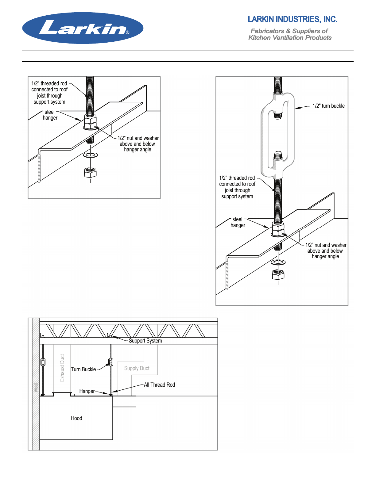
Basic Hanging Methods
Figure 1
Simple hanging method that requires all
thread, two washers, and three ½” heavy
nuts.
Figure 2
Example of using ½” turn buckle
designed for easy adjustment of hood level.
Figure 3
An overview of using turn buckles
for hood installation. Methods of hood
Installations may vary depending on
local code requirements.
Note: Hanging material provided by
others.
2
Page 5
Commercial Kitchen Hood
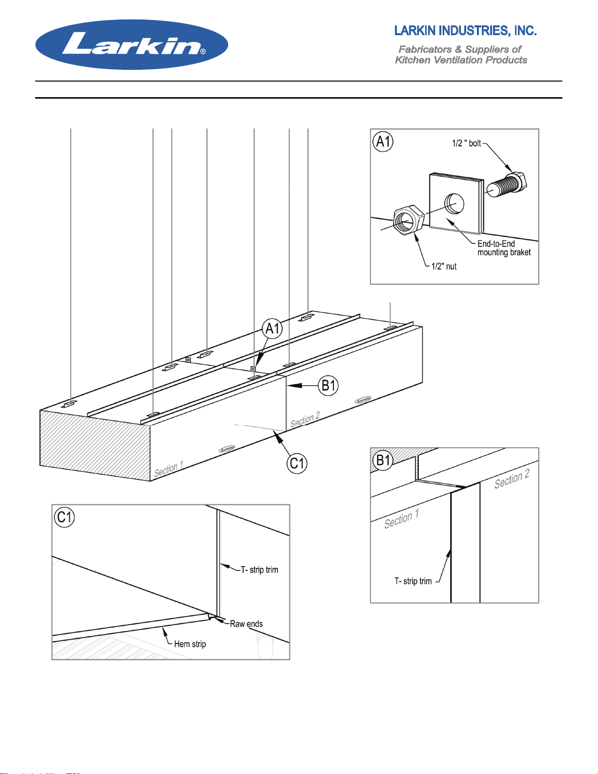
End-to-End Configuration
Align hoods and bolt together.
Apply silicone to seam between hood sections.
insert “T” strip and temporarily attach with tape.
After silicone has dried, remove tape.
Slide hem strip over raw ends of hood sections Note: Hanging material provided by others.
and pop rivet in place.
3
Page 6

Commercial Kitchen Hood
Back-to-Back Configuration
Align hoods and bolt together.
Apply silicone to seam between hood sections. Note: Hanging material provided by others.
insert “T” strip and temporarily attach with tape.
after silicone has dried, remove tape.
4
Page 7

Commercial Kitchen Hood
Grease Trough and Cup Installation
NOTICE
No two kitchens are the same
and require different schedules
of maintenance. Check grease
cup daily for the first few weeks
of normal operation to determine
a proper cleaning schedule. The
grease cup will need to be emp tied more frequently with heavier
cooking loads.
Hang grease cup on the key studs provided below the filter rack.
Slide grease trough over the two key studs at an angle with the smaller portion of the keyhole at
the top position. Slide trough down to lock into place. Once the trough has been installed, check to
make sure it is tilted towards the grease cup shown in the figure below.
VERY IMPORTANT
Make sure that the small
portion of the keyhole is in
the up position for proper
Installation.
5
Page 8

Commercial Kitchen Hood
Hood Options 1.1 Back Return Plenum
Hang Back Return
Plenum at standard
hanging height. (8’-6”
top) with threaded rod
attach to wall at bottom.
hang Hood against Back
Return Plenum.
Note: Hanging material
provided by others.
6
Page 9

Commercial Kitchen Hood
Hood Options 1.2 Front Perforated Supply Plenum (FPSP)
Hang FPSP using all thread rod against the
upper front of the hood. Attach plenum to
channel located on the front edge of the hood.
Collars maybe shipped mounted or loose. If the
collars are loose, install diffuser plate, attach
collar to the plenum, and seal.
Standard FPSP (12”-16”)
Note: Hanging material provided by others.
Seal collars using approved methods.
Double Discharge (FPSP-AC)
7
Page 10

Commercial Kitchen Hood
Hood Options 1.3 Stainless Steel Wall Splash Panels
Each overlap reduces the overall length by 3/8”. Add the number of overlaps and multiply by 3/8”.
Divide this measurement by two. Start the first panel (no overlap) at this distance from the end of
hood. Install remaining panels using
overlap to trim
previous panel. Use
side trim to extend
panels flush with
ends of the hood.
Inside and/or outside
corner trim my also
be used. Overlap
omitted on one piece
wall panels.
8
Page 11

Commercial Kitchen Hood
Hood Options 1.4
Ceiling Enclosure
Note: Fastening material
provided by others
9
End Curtains
Page 12

Duct Work
Ductwork Installation
Upon customer request, Larkin Industries, Inc.
may furnish ductwork. All ductwork should be
installed in accordance with local codes. The
installing contractor is responsible for adherence to codes and restrictions. Generally, the
duct system will perform best and will insure
easy installation if installed in the most direct
and simple manner.
NFPA-96 requires that the exhaust duct must
be installed using 16-gauge carbon steel or
18-gauge stainless steel with all joints and
seams welded liquid tight. Listed factory built
grease duct is an exception when installed
according to manufactures instructions.
NFPA-96 further requires that a minimum of
500 FPM (Feet Per Minute) velocity must be
maintained in the exhaust duct. There is not a
specified maximum; however exhaust velocity
should not exceed 2200 FPM. Install access
panels where required. In any event,
conformance to local codes must be adhered
to, unless variance is obtained.
Make-up air ductwork should contain
adequate filtering provisions somewhere in
the system before it is introduced into kitchen
space, or in the hood. Select hood models
require a make-up air fire damper with fusible
link installed at the collar. Access to the
fusible link must be installed in supply duct.
Only use rigid type duct for make-up air. Do
not use “flex” duct. This duct should be in
accordance with project specifications and
installed in accordance with standard
SMACNA Low Pressure requirements.
Field Installed Duct Collars
Exhaust and Supply collars are shipped loose
(not connected to hood) and intended to be
field installed on some projects. Determine the
location of exhaust/supply collar(s). Collars
should be located as close to center (left to
right) of hood as possible. When two exhaust
and/or supply collars are required, equal
distance between collars (left to right) should
be maintained. Loose collars are tack welded
to top of hood (back of crate). Break tack
welds to remove collars. Exhaust collars must
be folded up before installing. Fire Dampers
are shipped loose inside the crate.
Exhaust Collars
When installing exhaust collar(s), cut hole(s)
in exhaust plenum as close to center as
possible, the size of exhaust collar. Attach
collar(s) to the plenum with continuous liquid
tight external welds, per NFPA-96. For collar
to duct connection see “Exhaust Duct
Systems” Chapter 7 of NFPA-96.
Supply Collars
Same as exhaust collar(s), cut hole(s) in
make-up air plenum as close to center as
possible, 1inch from the front edge of hood,
the size of the supply collar(s). Attach collar(s)
to hood and seal per local standard for duct
connections.
Important: Refer to your AHJ (Authority
Having Jurisdiction) for requirements and/or
questions on local codes.
Clearance to Combustible Materials
A further note on ductwork is important.
NFPA- 96 states: “Where 18 in. clearance is
required for unprotected combustible material,
the clearance may be reduced if the
combustible material is protected by an
engineered construction system acceptable to
the authority having jurisdiction, or by the use
of materials or products listed for protection
purposes”. Consult NFPA-96 and local codes,
before installing any hood system or exhaust
ductwork.
10
Page 13

Wiring and Start-Up
Wiring
A licensed electrician familiar with commercial
kitchen hood installation should perform
wiring.
Complete all wiring required to controls, lights,
fans, etc. When a master control panel is
furnished with the hood system, follow the field
wiring instructions included with the panel.
When master control panel is not furnished,
complete in accordance with the project
criteria.
Electrical systems should be installed in
accordance with NEC (National Electrical
Code) with disconnecting means, proper
fusing and grounding system to protect
against hazardous shock.
Start-Up
Determine that the installation is complete and
in accordance with the project plans and
specifications, that the duct system is
complete and that all electrical connections
have been made.
Check all motors, coils, etc., for proper voltage
and connection. See that all electrical
components have adequate accessibility and
that all connections are tight. Place the system
into operation as provided for in the control
sequence.
By physical observation, check the supply and
exhaust fans for proper operation by checking
voltage, motor overload, noise level,
amperage, rotation, etc. Verify that motors and
bearings have proper lubrication and that the
belts have proper tension. Verify air intake
filters are in place and clean. Make sure inlet
damper (if required) is installed in hood
(supply collar) and opened. Airflow in the
supply duct should be verified by taking a duct
traverse if possible. If this is not possible, the
average velocity across the supply nozzle
should be taken with a rotating vane
anemometer, or other instrument. Determine
the supply CFM by multiplying the average
velocity by the cross sectional area of the duct
in square feet or the net free area of the
supply nozzle in square feet.
Capacity of the exhaust system should be
determined by a duct traverse if possible and if
this is not possible, take an average reading
with a rotating vane anemometer across the
filter bank. Multiply the average velocity by the
cross sectional area of the duct in square feet
or by the net free area of the filter bank.
If the airflow, as measured, is not in accordance with the project specifications, adjust the
speed of the respective fan(s) as required and
re-check (see fan installation instructions).
After the system has been placed in operation
and balancing has been accomplished, a
visual inspection should be made of the entire
system. Inspection should include such things
as unusual noises, excessive exhaust or
supply air, and general operation.
If smoke is not being exhausted properly,
check exhaust fan operation (is it on?).
Determine if exhaust air is sufficient. If the air
is sufficient, balance the supply air with the
damper in the supply collar until all products of
combustion are being exhausted. All parts of
the system should be left in a clean and
polished condition. Always instruct
owner/operator in the proper operation
maintenance.
11
Page 14

Maintenance
Hood
Inspect the grease extractors each day for
grease deposits, clean if necessary. Check the
grease container every day and empty. Wipe
the interior/exterior of the hood daily, if
possible, to remove deposits or accumulations
of grease. Periodically clean the interior of
hood and light fixtures with a mild detergent as
necessary.
Scratches on the stainless steel hood can be
removed with an abrasive pad (e.g. ScotchBrite) or similar cloth, being extremely careful
to always rub in the direction of the metal
grain.
After removing any scratches or imperfections,
clean the entire hood with a stainless steel
polish (e.g. Shiela-Shine). Once polish has
been applied, remove excess with a dry cloth.
Caution: Do not use steel wool pads,
scrapers, etc. to clean stainless steel surfaces.
Do not use chlorine or chlorine based
substances, acids, or chloride based
substances on or around the hood. Vapors
from these substances can cause corrosion on
stainless steel.
Clean exhaust duct quarterly to prevent
grease accumulation.
Notice: If a kitchen ventilation hood is cleaned
with pressure-washer or steam cleaner, the
silicone sealant will be removed from the
sealed seams. Standard daily cleaning over
time will loosen the seal and the silicone will
be removed from the sealed seams.
The sealant may be replaced, after a thorough
cleaning and de-greasing, with a food grade
high temperature silicone. Clean grease
extractors daily in a dishwasher or other
containers with a mild detergent in warm/hot
water. Never use harsh or abrasive cleaners
on stainless steel.
Fans
Check cleanliness of supply fan intake filters
every two weeks, for the first month, to
establish a cleaning schedule. To clean filters,
remove supply fan lid, and filters. Flush filters
with warm soapy water and recoat with a
filter coat adhesive. Reinstall filters and lid.
Check tension of fan drive belts (exhaust and
supply) upon initial installation, and again after
a period of two weeks of operation. Belts tend
to stretch during the initial stages of service.
Inspect condition and tension of belts monthly
there after. Properly adjusted belt tension will
allow approximately 1/2” deflection on each
side of the belt, midway between the pulley
centers with slight finger pressure. Overly
tightened belts will cause wear, motor
overloading, bearing wear and noise.
Loose belts will cause belt wear, pulley wear,
and poor fan performance.
A monthly cleaning of exhaust fan wheel and
interior of housing is required. Heavy grease
build-up is a fire hazard and can also cause
wheels to be unbalanced. This leads to
bearing wear, undue noise, and poor fan
performance.
Oil and/or grease all motors and bearing every
six months or as conditions dictate. At least
once a year, check motor and fan shafts.
Clean and check tightness & alignment.
At least every six months, all electrical
connections should be inspected and checked
for tightness.
12
Page 15

Warranty
One-Year Warranty
Except for motors (see separate warranty on
motors), Larkin Industries, Inc. warrants to its
purchaser that each ventilator manufactured
by Larkin shall be free from defects in material
and workmanship for a period of one year
from the date of shipment by Larkin to the
original purchaser, if the ventilator has been
subjected to normal use and service. If it
appears within the warranty period that any
such ventilator or material used there in does
not meet the warranties specified above, the
purchaser must notify the Company
immediately. Failure to notify within a
reasonable time voids the warranty. The
Company agrees to remedy any such defect
promptly by either repair or replacement, at
the Company's sole discretion of any alleged
defective part (exclusive of motors covered
separately herein). Cost of installation or
removal of any failed unit or part thereof
will be the sole responsibility of the purchaser.
This warranty does not guarantee the proper
design or installation of any ventilator nor is
there any warranty concerning the ability of
the ventilator to remove smoke, grease, or
heat. There is no warranty that the ventilator
will be approved by, or meet, any local codes.
This is a material warranty only. If the
equipment has been altered or repaired in any
way, the Company shall have the right, in its
sole discretion, to void the warranty. If the
equipment has been improperly installed,
subjected to misuse, been subjected to
negligence, been subjected to accident, or
been improperly maintained or lubricated, the
Company shall have the right, in its sole
discretion, to void the warranty.
Notice:
Replacement of silicone sealant is not covered
by any warranty, express or implied, that is
issued by Larkin Industries.
Motor Warranty
Electric motors carry a three year limited
warranty. Larkin makes no warranty as to the
MERCHANTABILITY or that the goods will be
fit for any particular purpose. Larkin Industries,
Inc. shall not be responsible for any incidental
or consequential damages, the purchaser's
sole and exclusive remedy being the repair or
replacement set forth above. Larkin Industries,
Inc. shall have no responsibility for loss of use
of the equipment, loss of time, down time,
inconvenience, commercial loss, consumer
loss, loss of profits, or any other injuries or
damages beyond the repair or replacement as
set forth herein above. Larkin Industries, Inc.
is not responsible to purchaser, or anyone
else for any negligence, breach of contract, or
damages, except as specifically set forth
herein.
This warranty is expressly in lieu of all other
warranties, whether expressed or implied, and
in lieu of any and all obligations or liabilities on
the part of the Company. The Company
neither assumes, nor authorizes anyone to
assume for it, any liability which is not set forth
in the manufacturer's warranty. In the event
Larkin Industries, Inc. receives a verbal order,
there shall be no warranty that the goods will
be shipped as ordered. All such orders are
shipped at the risk of the buyer.
13
Page 16

Commercial Kitchen Hood
Trouble Shooting
The following is a list of common causes and corrective actions for possible problems with exhaust
hood systems. Please refer to this list prior to consulting manufacturer.
14
 Loading...