

Page 1

Page 2

Page 3

• Preface
This manual describes the operation of the following instrument.
Brand: LAQUA
Series name: LAQUA 200 Series Handheld Water Quality Meter
Model: LAQUA-PC210, LAQUA-PC220
Model description: pH/ORP/Conductivity Meter
Be sure to read this manual before using the product to ensure proper and safe operation of
the product. Also, safely store the manual so it is readily available whenever necessary.
Product specifications and appearance, as well as the contents of this manual are subject to
change without notice.
• Warranty and responsibility
HORIBA Advanced Techno Co., Ltd. warrants that the product shall be free from defects in
material and workmanship and agrees to repair or replace free of charge, at option of HORIBA
Advanced Techno Co., Ltd., any malfunctioned or damaged product attributable to
responsibility of HORIBA Advanced Techno Co., Ltd. for a period of Three (3) years from the
delivery unless otherwise agreed in a written statement. In any one of the following cases,
none of the warranties set forth herein shall be extended:
• Any malfunction or damage attributable to improper operation
• Any malfunction attributable to repair or modification by any person not authorized by
HORIBA Advanced Techno Co., Ltd.
• Any malfunction or damage attributable to the use in an environment not specified in this
manual
• Any malfunction or damage attributable to violation of the instructions in this manual or
operations in the manner not specified in this manual
• Any malfunction or damage attributable to any cause or causes beyond the reasonable
control of HORIBA Advanced Techno Co., Ltd. such as natural disasters
• Any deterioration in appearance attributable to corrosion, rust, and so on
• Replacement of consumables
HORIBA Advanced Techno Co., Ltd. SHALL NOT BE LIABLE FOR ANY DAMAGES
RESULTING FROM ANY MALFUNCTIONS OF THE PRODUCT, ANY ERASURE OF DATA,
OR ANY OTHER USES OF THE PRODUCT.
• Trademarks
• Microsoft, Windows, Windows Vista are registered trademarks or trademarks of Microsoft
Corporation in the United States and other countries.
Other company names and brand names are either registered trademarks or trademarks of the
respective companies. (R), (TM) symbols may be omitted in this manual.
CODE:M003657-3200793611-GZ0000553860
March,2019 © 2019 HORIBA Advanced Techno Co., Ltd.
I
Page 4

Regulations
• Regulations
• EU regulations
• Conformable standards
This equipment conforms to the following standards:
EMC: EN61326-1
RoHS: EN50581
Warning: This product is not intended for use in industrial environments. In an
industrial environment, electromagnetic environmental effects may
cause the incorrect performance of the product in which case the
user may be required to take adequate measures.
Class B, Basic electromagnetic environment
9. Monitoring and control instruments
• Information on disposal of electrical and electronic equipment and disposal of batteries and accumulators
The crossed out wheeled bin symbol with underbar shown on the product or accompanying
documents indicates the product requires appropriate treatment, collection and recycle for
waste electrical and electronic equipment (WEEE) under the Directive 2012/19/EU, and/or
waste batteries and accumulators under the Directive 2006/66/EC in the European Union.
The symbol might be put with one of the chemical symbols below. In this case, it satisfies
the requirements of the Directive 2006/66/EC for the object chemical. This product should not
be disposed of unsorted household waste. Your correct disposal of WEEE, waste batteries and
accumulators will contribute to reducing wasteful consumption of natural resources, and
protecting human health and the environment from potential negative effects caused by
hazardous substance in products.
Contact your supplier for information on applicable disposal methods.
• Authorised representative in EU
HORIBA UK Limited
Kyoto Close, Moulton Park,
Northampton, NN3 6FL, United Kingdom
II
Page 5

Regulations
• FCC rules
FCC Compliance Statement
This device complies with part 15 of the FCC Rules. Operation is subject to the following two
conditions: (1) This device may not cause harmful interference, and (2) this device must accept
any interference received, including interference that may cause undesired operation.
Responsible Party for FCC matter
HORIBA Instruments Incorporated
Head Office
9755 Research Drive
Irvine, California 92618 USA
+1 949 250 4811
Note
This equipment has been tested and found to comply with the limits for a Class A digital device,
pursuant to part 15 of the FCC Rules. These limits are designed to provide reasonable
protection against harmful interference when the equipment is operated in a commercial
environment. This equipment generates, uses, and can radiate radio frequency energy and, if
not installed and used in accordance with the instruction manual, may cause harmful
interference to radio communications. Operation of this equipment in a residential area is likely
to cause harmful interference in which case the user will be required to correct the interference
at his own expense.
Any changes or modifications not expressly approved by the party responsible for compliance
could void the user's authority to operate the equipment.
• Korea certification
• Taiwan battery recycling marks
III
Page 6

Regulations
• China regulation
标记的意义
Meaning of Marking
本标记适用在中华人民共和国销售电器电子产品,标记中央的数字
表示环境保护使用期限的年数。( 不是表示产品质量保证期间。)
只要遵守这个产品有关的安全和使用注意事项,从制造日开始算起
在这个年限内,不会给环境污染、人体和财产带来严重的影响。请
不要随意废弃本电器电子产品。
This marking is applied to electric and electronic products sold in
the People's Republic of China. The figure at the center of the
marking indicates the environmental protection use period in
years. (It does not indicate a product guarantee period.) It
guarantees that the product will not cause environment pollution
nor serious influence on human body and property within the
period of the indicated years which is counted from the date of
manufacture as far as the safety and usage precautions for the
product are observed. Do not throw away this product without any
good reason.
IV
Page 7

Regulations
产品中有害物质的名称及含量
Name and amount of hazardous substance used in a product
有害物质
Hazardous substances
部件名称
Unit name
本体
Main unit
电池
Battery
AC 适配器
AC adopter
电缆
*2
Cable
支架
*2
Stand
打印机
*2
Printer
电极
Electrode
本表格依据 SJ/T 11364 的规定编制。
This form is prepared in accordance with SJ/T 11364.
○ : 表示该有害物质在该部件所有均质材料中的含量均在 GB/T 26572 规定的限量要
求以下。
Denotes that the amount of the hazardous substance contained in all of the
homogeneous materials used in the component is below the limit on the acceptable
amount stipulated in the GB/T 26572.
×: 表示该有害物质至少在该部件的某一均质材料中的含量超出 GB/T 26572 规定的
限量要求。
Denotes that the amount of the hazardous substance contained in any of the
homogeneous materials used in the component is above the limit on the acceptable
amount stipulated in the GB/T 26572.
铅
Lead
(Pb)
*1,*2
*2
汞
Mercury
(Hg)
× ○○ ○ ○ ○
× ○○ ○ ○ ○
× ○○ ○ ○ ○
× ○○ ○ ○ ○
○○○ ○ ○ ○
× ○○ ○ ○ ○
× ○ × ○○ ○
镉
Cad mium
(Cd)
六价铬
Hexavalent
chromium
(Cr (VI))
多溴联苯
Poly
bromobi-
phenyl
(PBB)
多溴二苯醚
Poly
bromo-
diphenyl
ether
(PBDE)
*1: 本部件的环保使用期限为 10 年。 The environmental protection use period
of this product is 10 years.
*2: 选配件 Optional products
V
Page 8

For Your Safety
• For Your Safety
• Hazard classification and warning symbols
Warning messages are described in the following manner. Read the messages and follow the
instructions carefully.
• Hazard classification
This indicates an imminently hazardous situation which, if not
avoided, will result in death or serious injury. This is to be
limited to the most extreme situations.
This indicates a potentially hazardous situation which, if not
avoided, could result in death or serious injury.
This indicates a potentially hazardous situation which, if not
avoided, may result in minor or moderate injury. It may also
be used to alert against unsafe practices.
• Warning symbols
Description of what should be done, or what should be
followed.
VI
Description of what should never be done, or what is
prohibited.
Page 9

For Your Safety
• Safety precautions
This section provides precautions for using the product safely and correctly and to prevent
injury and damage. The terms of DANGER, WARNING, and CAUTION indicate the degree of
immanency and hazardous situation. Read the precautions carefully as it contains important
safety messages.
• Instrument and electrode
Do not disassemble or modify the instrument. Otherwise, it may heat up or be ignited
resulting in a fire or an accident.
Harmful chemicals
Some electrodes are used with hazardous standard solutions. Handle them with care.
The internal solution of pH electrode is highly concentrated potassium chloride (3.33
mol/L KCl). If the internal solution comes in contact with the skin, wash it off
immediately. If it gets into the eyes, flush with plenty of water and then consult a
doctor.
Broken glass
Broken glass may cause injury. The outer tube and tip of an electrode are made of
glass. Handle them with care.
Do not use the phono jack under wet or humid conditions. Otherwise, it may cause a
fire, electric shock, or breakage.
VII
Page 10

For Your Safety
• Battery
Keep batteries out of reach of children. If someone accidentally swallows a battery,
consult a doctor immediately.
If alkaline fluid from a battery gets into the eyes, do not rub the eyes, rinse with clean
water immediately and then consult a doctor. Contact with alkaline fluid could cause
blindness.
Do not put batteries in a fire, expose to heat, disassemble or remodel.
Doing so can case fluid leakage, overheating or explosion.
VIII
Page 11

Product Handling Information
• Product Handling Information
• Operational precautions (instrument)
• Only use the product including accessories for their intended purpose.
• Do not drop or physically impact the instrument.
• The instrument is made of solvent-resistant materials but that does not mean it is resistant
to all chemicals. Do not expose the instrument in strong acid or alkali solution, or wipe with
such solution.
• If the instrument is dropped into water or gets wet, wipe it using soft cloth. Do not heat to
dry it.
• The instrument has a dust-proof and waterproof structure i.e., the instrument does not
malfunction even when immersed in water of 1 m depth for 30 minutes. This does
guarantee non-destructive, trouble-free, dust-proof, and waterproof performance in all
situations.
• When replacing the batteries or when a serial cable connected, the instrument does not
have the dust-proof and waterproof performance. The dust-proof and waterproof
performance is maintained only when the covers are attached correctly.
• After replacing the batteries or removing the serial cable connected, make sure that the
waterproof gasket attached to the cover is not deformed or discolored, or has foreign
matter adhering to it. If the waterproof gasket is deformed, discolored or has foreign matter
adhering to it, dust could get inside, water leaks could occur that could lead to instrument
malfunction.
• To disconnect an electrode or serial cable, hold the connector and pull it off. If you pull at
the cable, it may cause breakage.
• The phono jack communication between the instrument and a personal computer (referred
to as PC in the rest of this document) may fail because of environmental conditions, such
as electromagnetic noise.
• Do not replace the batteries in a dusty place or with wet hands. Dust or moisture could get
inside the instrument, possibly causing instrument malfunction.
• Do not use an object with a sharp end to press the keys.
• If the power supply is interrupted while measurement data is being saved in the instrument,
the data could be corrupted.
• A NiMH rechargeable battery can be used in this instrument.
• Operational precautions (battery)
• Do not short circuit a battery.
• Position the + and side of the battery correctly.
• When the battery has depleted or the instrument will not be used for a long time, remove
the batteries.
• Of the specified battery types, make sure to use two batteries of the same type.
• Do not use a new battery together with a used battery.
• Do not use a fully charged nickel-metal hydride battery together with a partially charged
battery.
• Do not attempt to charge a non-rechargeable battery.
IX
Page 12

Product Handling Information
• Environmental conditions for use and storage
• Temperature: 0 °C to 45 °C
• Humidity: under 80% relative humidity and free from condensation
• Avoid the following conditions:
• Strong vibration
• Direct sunlight
• Corrosive gas environment
• Locations close to an air-conditioner
• Direct wind
• Transportation
When transporting the instrument, repackage it in the original package box. Otherwise, it may
cause instrument damage.
• Disposal
• Standard solution used for the calibration must be under neutralized before the disposal.
• When disposing of the product, follow the related laws and regulations of your country for
disposal of the product.
X
Page 13

Contents
■ Product Overview .............................................................. 1
● Package Content........................................................ 1
● Key Features .............................................................. 2
● Product components................................................. 3
■ Basic operations................................................................ 7
● Mode and measurement............................................ 9
■ Calibration........................................................................ 11
● pH Calibration .......................................................... 11
● ORP/mV Calibration................................................. 13
● Conductivity Calibration ......................................... 15
● TDS calibration ........................................................ 18
● Salinity calibration................................................... 19
● Temperature Calibration ......................................... 21
■ Data................................................................................... 23
● Data capture and storage........................................ 23
● Data transfer............................................................. 24
■ Setup................................................................................. 25
● P1 pH setup .............................................................. 25
● P1 COND setup ........................................................ 29
● P2 TDS setup............................................................ 36
● P3 SAL setup............................................................ 39
XI
Page 14

Contents
● Data setup ................................................................ 43
● General setup........................................................... 50
● CLK setup................................................................. 59
■ Maintenance and storage ............................................... 64
● Maintenance and storage of the instrument ......... 64
● Maintenance and storage of electrodes ............... 65
■ Error messages and trouble shooting........................... 67
■ Appendix .......................................................................... 72
● Appendix 1 ............................................................... 72
● Appendix 2 ............................................................... 74
● Appendix 3 ............................................................... 74
XII
Page 15

Product overview
1
2
3 5
4
■ Product Overview
This section describes the package content, key features and product components of LAQUA
PC200 handheld meters.
● Package Content
After opening the carry case, remove the meter and check for damage on the instrument and
confirm that the standard accessories all exist. If damage or defects are found on the product,
contact your dealer.
LAQUA PC200 Series Handheld meter and meter kit include the following items:
S.NO. Name
1 Instrument
2 Instruction manual
3 2 AA batteries
4 Electrodes
5 Calibrating solutions
1
Page 16

Product overview
● Key Features
• IP67 water ingress, dust-proof, shock-resistant, anti-slip meter housing.
• Large monochrome LCD (50 x 50 mm) with white LED back lighting.
• Built-in electrode holder (up to 2 electrodes).
• Foldable meter stand.
• Simple user interface and single parameter display.
• 500 (for PC210) / 1000 (for PC220) data memory.
• Automatic Temperature Compensation (ATC) with temperature calibration.
• Adjustable auto shut-off time (1 to 30 minutes).
• Auto-hold / Auto stable / Real-time measurement modes with stability indicators.
• Powered by 2 x AA batteries.
• Real-time clock (only for PC220).
• PC (standard USB) / Printer (25 pin serial) connection via 2.5 mm diameter phono jack.
2
Page 17

Product overview
● Product components
No Name Function
1 Monochrome LCD Displays the measured value
2 Operation keys Used for instrument operation
3 Electrode connector Connect to the BNC connector of the electrode
4 Temperature connector (T) Connect to the temperature sensor of the electrode
5 Battery cover Open/close to insert/remove batteries
6 Electrode holder Hold the electrode to carry with the instrument
7 Meter stand
8 Serial connector Connects to the PC or printer with the appropriate cable
Open stand to place the meter at an inclined position on a
flat surface
3
Page 18
Product overview
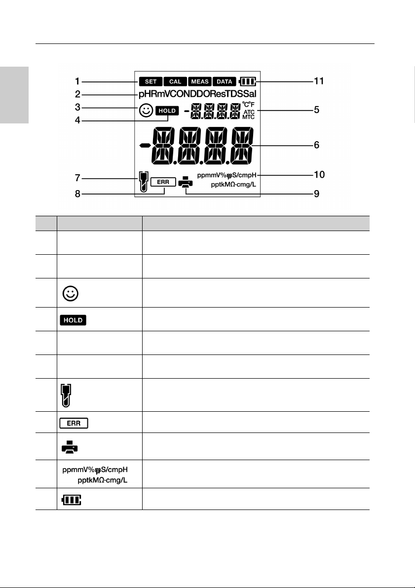
● Display
No Name Function
1 Status Icon
2 Parameters
3
4
Temperature display
5
area
Measured value, set
6
item display area
7
Displays the current operation mode (Setup, Calibration,
Measurement and Data mode)
Displays the measured parameters like pH, RmV, COND, Res,
TDS and Sal
Stability indicator shows value is stable for documentation in
Auto Stable and Auto Hold modes
Appears when the measured value display is stable and fixed in
auto-hold mode
Displays the measured temperature
Displays the measured value and the set value
Indicates electrode sensitivity level
8
9 Indicates data being transfered to the printer or computer
10 Displays the unit for the measurement parameter
11 Displays the battery level
Indicates error situation
4
Page 19

● Battery level display
100% battery life
50% battery life
20% battery life
Batteries are weak and need replacement. Refer “ BATT LOW ” (page 67) to
solve this
● Electrode sensitivity level
Electrode sensitivity above 95%(excellent)
Electrode sensitivity between 85% to 95% (very good)
Electrode sensitivity between 80% to 85%(good). Refer “ SLPE ERR ” (page
67) to solve this
Product overview
5
Page 20

Product overview
● Keypad operation
Keypad Name Function
CAL key
MEAS key
DATA key Switches from the measurement mode to the data mode.
MODE key In the measurement mode, changes measurement parameters.
SET key Switches from the measurement mode to the setup mode.
ENTER key
UP key
DOWN key
POWER key Powers ON/OFF the instrument.
Switches from the measurement mode to the calibration mode.
Starts calibration in the calibration mode.
Switches the operation mode to the measurement mode.
Releases the fixed measurement value mode in the auto hold
mode and begins a fresh measurement.
Determines the selection or setup.
Saves data in the measurement mode and calibration mode.
In the setup mode, navigates between various setups.
Selects preferred option in some setup screens.
Increases or decreases selected digit when entering numbers.
6
Page 21

Basic operations
Note
■ Basic operations
This section describes function and basic operation method of each part of LAQUA PC200
handheld meter.
● Turning on the instrument
Inserting the batteries
This instrument is operated by batteries. You can use
AA alkaline batteries or AA Ni- MH chargeable
batteries. Perform the following procedure to insert
batteries in the instrument.
1. Unscrew the battery cover on the back of the
instrument counter-clock wise to unlock the battery cover.
2. Remove the battery cover and set the batteries
inside.
3. Replace battery cover.
4 . S c r e w t h e b a t t e r y c o v e r o n t h e b a c k
of the instrument clockwise to lock the battery
cover.
• Do not replace the batteries in a dusty place or with wet hands. Dust or moisture could get
inside the instrument and possibly cause an instrument malfunction.
• Do not short-circuit a battery.
• Note polarity as shown in the battery compartment.
• When the battery has depleted or the instrument is not used for a long time, remove the
batteries.
• Of the specified battery types, make sure to use two batteries of the same type.
• Do not use a new battery together with an used battery.
7
Page 22

Basic operations
Electrode connector
Temperature jack (T)
● Connecting an electrode
To perform calibration/ measurement, it is necessary to use the appropriate electrode for
measurement parameter. Recommended electrodes for various sample are listed in our
product catalog. Use the following procedure to correctly connect the electrode to the
instrument:
1. Insert the electrode connector by fitting its groove with the connector pin of the instrument (refer below table).
2. Turn the electrode connector clockwise by following the grooves.
3. Slide the connector cover on the connector.
4. When using a combination electrode equipped with a temperature sensor, insert the temperature jack (T) to the ATC socket on the meter.
CH1 CH2
pH Electrode Conductivity Electrode
8
Page 23
Basic operations
● Mode and measurement
● Changing the operation mode
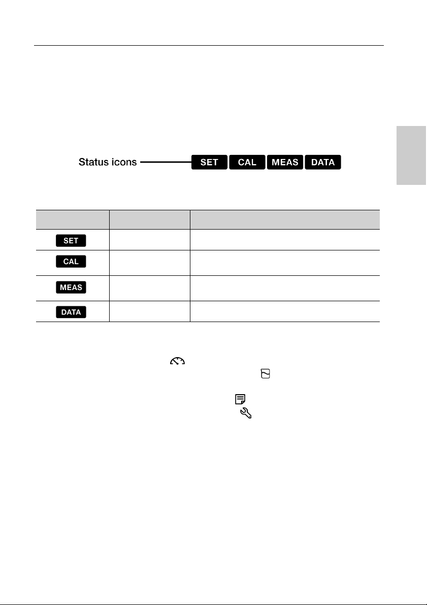
You can change the operation mode to four available modes depending on the purpose of use.
The status icon indicates the current mode.
Icon Name Function
Setup mode Perform various setup functions.
Calibration
mode
Measurement
mode
Data mode Performs data setup. Displays the saved data.
You can change the operation mode using the corresponding key:
• Measurement mode: Press the key to change to the measurement mode.
• Calibration mode: In the measurement mode, press the key to change to the
calibration mode.
• Data mode: In the measurement mode, press the key to change to the data mode.
• Setup mode: In the measurement mode, press the key to change to the setup mode.
Performs calibration.
Performs measurement.
9
Page 24

Basic operations
● Changing the measurement parameter
This instrument measures multiple parameters. For measurement, an electrode corresponding
to the measurement parameter is required. In the measurement mode, the measurement
parameter can be changed by pressing the key.
10
Page 25

pH calibration
Note
Tip
■ Calibration
This section describes the basic calibration method using LAQUA PC200 handheld meter, pH
and conductivity electrode.
● pH Calibration
Calibration is necessary for accurate pH measurement. To perform pH calibration, follow the
procedure detailed below:
Prerequisites
• Clean the pH electrode with DI (deionized) water and wipe it with tissue paper.
• Switch on the PC meter and plug in the pH electrode.
• Prepare buffer solution required for calibration.
• Keep the meter in pH measurement mode.
• Dip the pH electrode at least 3 cm in the calibration solution.
• Perform two-point calibration using:
pH 7 and 4 for acidic sample.
pH 7 and 10 for alkaline sample.
• Perform three-point calibration using pH7, 4 and 10 if you are unsure of the expected
sample pH value. It is recommended to calibrate with pH7 first.
• Default buffer setup is BUFF USA. If you want to change to BUFF NIST or BUFF DIN,
refer to “P 1.1 Buffer selection” on page 26.
• To abort an ongoing calibration process at any point of time, press the key.
• It is recommended to clear the previous calibration data before performing calibration. For
erasing the calibration data, refer to “P 1.3 Erase calibration data” on page 28.
11
Page 26

pH calibration
Note
Calibration
1. After placing the pH electrode in the buffer solution, press the key.
2. The selected buffer standard appears on the meter screen and meter starts checking
various calibration values with a blinking on screen.
3. Wait for the to stabilize (stable calibration reading).
4. Press the ENT key to confirm and save calibration data.
5. Meter displays DONE indicating end of the pH calibration procedure.
If you want to know previous calibrated values, press the key when you are in the CAL
mode.The display scrolls through the calibrated values and indicates slope and offset values.
12
Page 27

ORP calibration
Note
Tip
● ORP/mV Calibration
Calibration is necessary for accurate ORP measurement. To perform ORP calibration, follow
the procedure detailed below:
Prerequisites
• Clean the ORP electrode with DI (deionized) water and wipe it with tissue paper.
• Switch on the PC meter and plug in the ORP electrode.
• Prepare standard solution required for calibration.
• Ensure that the meter is in mV measurement mode.
• Dip the ORP electrode into the standard solution ensuring that the solution level is at least
3 cm from the electrode tip.
• Absolute value measurement mode and relative value measurement mode are the two
types of measurement mode available for ORP (mV) measurement.
• In absolute value measurement mode, the handheld meter displays the actual voltage
value.
• In relative value measurement mode, user can adjust the absolute mV value by calibration.
If the mV value is adjusted, the meter automatically indicates relative mV value as RmV.
The adjustment mV is applied as an offset to the absolute mV value.
• In the relative mV mode, the absolute mV value can be adjusted by ± 200 mV.
To abort an ongoing calibration process at any point of time, press the key.
13
Page 28

ORP calibration
Calibration
1. After placing the electrode in the solution, press the key to switch to mV mode.
2. Press the key.
3. Meter starts reading mV values and the blinks until value stabilizes.
4. Wait for the to stabilize (stable calibration reading).
5. Use the keys to adjust the mV value to your desired value.
6. Press the ENT key to confirm and save calibration data.
7. Meter displays DONE that indicates end of the ORP/mV calibration procedure.
14
Page 29

Conductivity calibration
Note
Tip
● Conductivity Calibration
Calibration is necessary for accurate electrical conductivity measurement. To perform
conductivity calibration, follow the procedure detailed below:
Prerequisites
• Clean the conductivity electrode with DI (deionized) water and wipe it with tissue paper.
• Switch on the PC meter and plug in the conductivity electrode.
• Prepare standard solution required for calibration.
• Press the key to keep the meter in COND mode.
• Dip the conductivity electrode in the standard solution till the hole at the upper part of the
electrode is immersed.
• Salinity, TDS, and resistivity of a sample solution are calculated from the measured value
of conductivity.
• In conductivity calibration mode, the default calibration method is Auto calibration. If you
like to change it to manual calibration method, refer “P 1.3 calibration mode setup” on
page 32.
• For second or multiple point calibration, clean the conductivity electrode with DI water and
follow the same procedure.
• If you are performing multiple point calibration, calibrate to the lowest conductivity first and
then move to increasing conductivity values. This minimizes cross contamination.
• To abort an ongoing calibration process at any point of time, press the key.
15
Page 30

Conductivity calibration
Calibration
Auto calibration
1. After placing the conductivity electrode in the standard solution, press the key.
2. Meter displays “Auto cal” as per set calibration method and starts measuring various
calibration values with a blinking on screen.
3. Wait for the to stabilize (stable calibration reading).
4. Press the ENT key to confirm and save calibration data.
5. Meter displays DONE indicating end of the conductivity calibration procedure.
6. Repeat for other calibration points as required.
7. You can calibrate at one point for each range
16
Page 31

Conductivity calibration
Manual calibration
1. After placing the conductivity electrode in the standard solution, press the key.
2. Meter displays “Manual cal” as per set calibration method and starts measuring various
calibration values with a blinking on screen.
3. Wait for the to stabilize (stable calibration reading).
4. Use the keys to enter the electrical conductivity value of the standard solution used for calibration.
5. Press the ENT key to confirm and save calibration data.
6. Meter displays DONE indicating end of the conductivity calibration procedure.
7. Repeat for other calibration points as required.
8. You can calibrate at one point for each range.
17
Page 32

Conductivity calibration
Note
● TDS calibration
TDS (Total dissolved solids) is calculated from the measured conductivity value. So no TDS
calibration is required and once conductivity mode is calibrated, TDS values will be recalibrated
accordingly.
Set the required TDS curve in LAQUA EC200 handheld meter. Available TDS curves are;
- LINR (Linear factor with adjustable factor from 0.4 to 1.0)
- 442 (Myron L 442 non-linear curve)
- EN (European environmental standard non-linear curve)
- NACL (non-linear salinity curve)
To set a desired TDS method, refer “P 2.1 TDS curve selection” on page 37.
18
Page 33

Conductivity calibration
Note
Tip
● Salinity calibration
Calibration is necessary for accurate salinity measurement. To perform salinity calibration
using LAQUA PC220 conductivity handheld meter, follow the procedure detailed below:
Prerequisites
• Clean the conductivity electrode with DI (deionized) water and wipe it with tissue paper.
• Switch on the PC meter and plug in the conductivity electrode.
• Prepare standard solution required for calibration.
• Press the key to keep the meter in SAL mode.
• Dip the conductivity electrode in the standard solution till the hole at the upper part of the
electrode is immersed.
• Before salinity calibration, set the required salinity method. In LAQUA PC220 handheld
meter, available salinity methods are;
- NACL
- SEA.W (Sea water)
• To set a desired salinity method, refer “P 3.2 select salinity type” on page 41.
• User can adjust the salinity value by calibration.
• For second or multiple point calibration, clean the conductivity electrode with DI water and
follow the same procedure.
• To abort an ongoing calibration process at any point of time, press the key.
19
Page 34

Conductivity calibration
Calibration
1. After placing the conductivity electrode in the standard solution, press the key.
2. Meter starts measuring various calibration values with a blinking on screen.
3. Wait for the to stabilize (stable calibration reading).
4. Use the keys to adjust the salinity value.
5. Press the ENT key to confirm and save calibration data.
6. Meter displays DONE indicating end of the salinity calibration procedure.
20
Page 35

Temperature calibration
Note
Tip
● Temperature Calibration
Temperature calibration is required to accurately match pH or conductivity electrode to the
meter. Check the temperature reading and if its acceptable, no temperature calibration is
required. If you need to calibrate, please follow the procedure detailed below:
Prerequisites
• Clean the pH or conductivity electrode with DI (deionized) water and wipe it with tissue
paper.
• Switch on the PC meter and plug in the pH or conductivity electrode and the temperature
sensor.
• Ensure to keep the PC meter in pH or mV measurement mode while using the pH
electrode for temperature calibration and in COND or TDS or Sal measurement mode
while using the conductivity electrode for temperature calibration.
• Dip the electrode in any calibration solution till its temperature sensor is immersed.
• Wait for 5 minutes to ensure temperature stability.
• Meter displays MTC if the temperature sensor is not plugged in and displays AT C if the
temperature sensor is plugged in.
• Temperature calibration must be performed using a known temperature solution or against
a calibrated thermometer.
To abort an ongoing calibration process at any point of time, press the key.
21
Page 36
Temperature calibration
Calibration
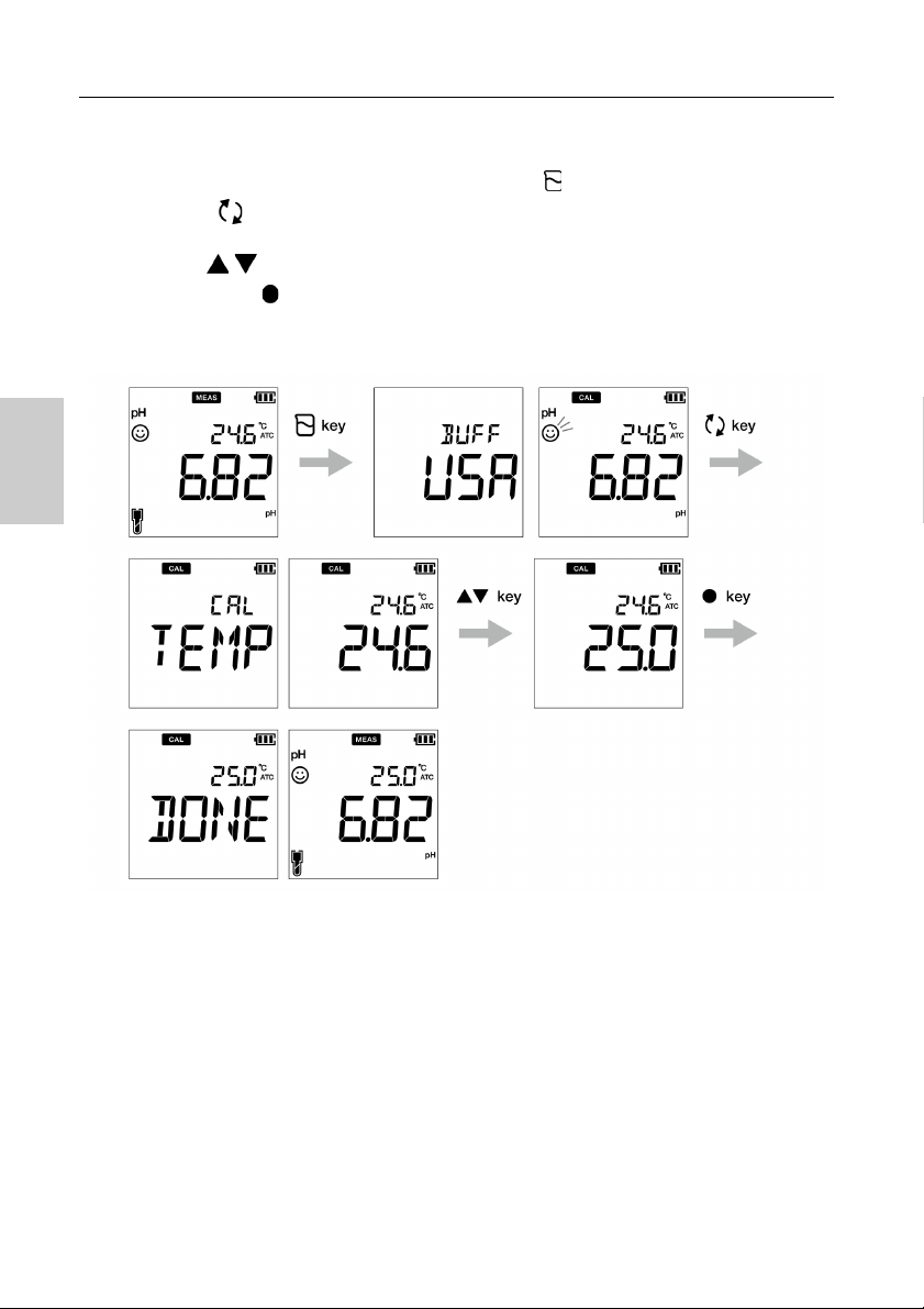
1. After placing the electrode in the solution, press the key.
2. Press the key to switch to temperature calibration mode. Meter displays measured
temperature value.
3. Use the keys to adjust the temperature to the required value.
4. Press the ENT key to save calibration data.
5. Meter displays DONE indicating end of the temperature calibration procedure.
22
Page 37

Data capture and stor age
Note
■ Data
This section describes the basic method of data storing and transferring using LAQUA 200
handheld meters.
● Data capture and storage
In LAQUA PC200 handheld meters, data measured by the instrument can be stored in the
internal memory.
To save the measured data:
• Press the ENT key to save the displayed data.
• Meter displays the saved data for 2 seconds and then the display returns to the previous
screen automatically.
• If the data storage limit reaches 500 in PC210 model or 1000 in PC220 model, memory full
error occurs and MEM FULL is displayed. To avoid memory full error, refer “Memory data
full” on page 67.
• In such case, print the data or transfer necessary data to a PC (only for PC220) and delete
the data from the internal memory of the instrument.
Viewing stored data
• To view stored data, press key .
• Use keys to review different stored records.
• Press key to get back to measurement mode.
23
Page 38

Data capture and storage
Tip
● Data transfer
● Transfer data to PC
Connect the instrument to a PC using phono jack to USB cable to transfer saved data to the
PC (for LAQUA PC220 only). Connect the phono jack at the instrument side to the
communication port on the PC.
● Print data
To print a desired data:
1. Being in the measurement mode, press key.
2. Use keys to view desired stored data.
3. Press key to print that individual data.
● Printer format- measurement
TDS
Meter Model : HORIBA PC220
Serial Number : 123456789
SW Revision : 1.00
Date : 20 Aug 2018
Time : 10:10:28
Mode : TDS
TDS : 1.23 g/L
Temperature : 25.0 C (MAN)
User Name :
Signature :
To print entire stored data log, refer “Print data setup” on page 46.
24
Page 39

pH set up
Note
Tip
■ Setup
This section describes all the setup functions available in LAQUA PC200 handheld meters.
● P1 pH setup
Using P1 pH setup function of the meter, you can:
• Select buffer standard
• Set calibration alarm
• Erase calibration data
To set the pH functions using LAQUA PC200 handheld meter, follow the procedure detailed
below:
Prerequisites
Switch on the PC meter.
• Default buffer setup is BUFF USA. You can change it to BUFF NIST or BUFF DIN if
required.
• Calibration alarm setup option must be used to avoid “Calibration interval alarm error” on
page 67 . You can set the calibration alarm for ---- day to upto 90 days, where ----
indicates “no calibration alarm” has been set.
• Erasing previous calibration data is recommended for accurate calibration. Default setup is
NO but to erase the calibration data, you need to change the setup to YES.
To return to the measurement mode, press the key.
25
Page 40

pH set up
● P 1.1 Buffer selection
1. Press the key, P1 PH screen appears.
2. Press the ENT
3. Press the ENT
4. Use the keys to change the buffer standard to BUFF NIST or BUFF DIN.
5. Press the ENT
selection.
key, P1.1 BUFF screen appears.
key, by default BUFF USA appears.
key, P1.1 BUFF screen appears. This indicates completion of buffer
26
Page 41

pH set up
● P 1.2 Calibration alarm setup
1. Press the key, P1 PH screen appears.
2. Press the ENT key, P1.1 BUFF screen appears.
3. Press the
4. Press the ENT key, by default DAYS ---- appears.
5. Use the keys to adjust the calibration alarm interval for next calibration.
6. Press the ENT key, P1.2 C.ALr screen appears. This indicates completion of calibration alarm setup.
key, P1.2 C.ALr screen appears.
27
Page 42
pH set up
● P 1.3 Erase calibration data
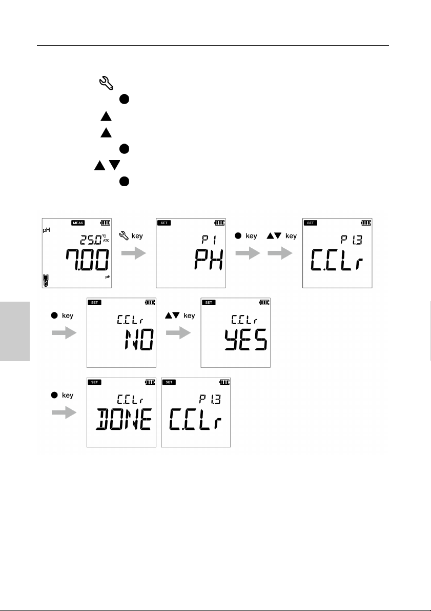
1.Press the key, P1 PH screen appears.
2.Press the ENT
3.Press the key, P1.2 C.ALr screen appears.
4.Press the key, P1.3 C.CLr appears.
5.Press the ENT key, C.CLr NO screen appears with NO as default setup.
6.Use the keys to change the setup to YES. This erases the calibration data.
7.Press the ENT
calibration data.
key, P1.1 BUFF screen appears.
key. P1.3 C.CLr screen appears. This indicates erasure of
28
Page 43

Conductivity set up
Note
Tip
● P1 COND setup
Using P1 COND setup function of the meter, you can:
• Set cell constant
• Select conductivity unit
• Set calibration mode
• Set temperature coefficient
• Set reference temperature
• Erase calibration data
To set the COND functions using LAQUA PC200 handheld meter, follow the procedure detailed
below:
Prerequisites
Switch on the PC meter.
• Default cell constant value is 1.00 and you can set a value in between 0.070 to 13.00.
• Default conductivity unit is set as S/cm. You can change the unit to S/m.
• Default auto calibration setup is ON but to perform manual calibration, you need to change
the setup to OFF.
• Default temperature coefficient is 2.00%. You can set a value in between 0.00% to 10.00%.
• Default reference temperature is 25.0 °C. You can set the value in between 15.0 °C to
30.0 °C.
• Erasing previous calibration data is recommended for accurate calibration. Default setup is
NO but to erase the calibration data, you need to change the setup to YES.
To return to the measurement mode, press the key.
29
Page 44
Conductivity set up
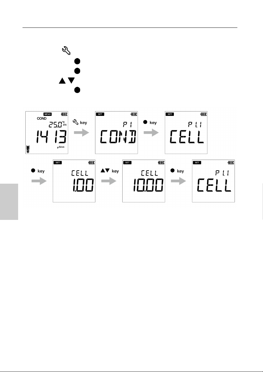
● P 1.1 Cell constant setup
1. Press the key, P1 COND screen appears.
2. Press the ENT
3. Press the ENT
4. Use the keys to set the cell constant in between 0.070 to 13.00.
5. Press the ENT
constant setup.
key, P1.1 CELL screen appears.
key, by default CELL 1.00 appears.
key, P1.1 CELL screen appears. This indicates completion of cell
30
Page 45

Conductivity set up
● P 1.2 Select conductivity unit
1. Press the key, P1 COND screen appears.
2. Press the ENT
3. Press the
4. Press the ENT key, by default UNIT S/cm appears.
5. Use the keys to change the conductivity unit to S/m.
6. Press the ENT key, P1.2 UNIT screen appears. This indicates completion of conductivity unit selection.
key, P1.1 CELL screen appears.
key, P1.2 UNIT screen appears.
31
Page 46

Conductivity set up
● P 1.3 calibration mode setup
1. Press the key, P1 COND screen appears.
3. Press the ENT
4. Press the key, P1.2 UNIT screen appears.
5. Press the key, P1.3 A.CAL appears.
6. Press the ENT
7. Use the keys to change the setup to OFF. This enables the manual calibration mode.
8. Press the ENT
auto calibration mode setup.
key, P1.1 CELL screen appears.
key, A.CAL ON screen appears with ON as default setup.
key. P1.3 A.CALscreen appears. This indicates completion of
32
Page 47

Conductivity set up
● P 1.4 Temperature coefficient setup
1.Press the key, P1 COND screen appears.
2.Press the ENT
3.Press the key, P1.2 UNIT screen appears.
4.Press the key, P1.3 A.CAL appears.
5.Press the key, P1.4 T.CFF appears.
6.Press the ENT
7.Use the keys to set the temperature coefficient in between 0.00% to 10.00%.
8.Press the ENT
temperature coefficient setup.
key, P1.1 CELL screen appears.
key, T.CFF 2.00% screen appears.
key. P1.4 T.CFF screen appears. This indicates completion of
33
Page 48

Conductivity set up
● P 1.5 Reference temperature setup
1.Press the key, P1 COND screen appears.
2.Press the ENT
3.Press the key, P1.2 UNIT screen appears.
4.Press the key, P1.3 A.CAL appears.
5.Press the key, P1.4 T.CFF appears.
6.Press the key, P1.5 T.rEF appears.
7.Press the ENT
8.Use the keys to set the temperature coefficient in between 15.0 °C to 30.0 °C.
9.Press the ENT
reference temperature setup.
key, P1.1 CELL screen appears.
key, T.REF 25.0 °C screen appears.
key. P1.5 T.rEF screen appears. This indicates completion of
34
Page 49
Conductivity set up
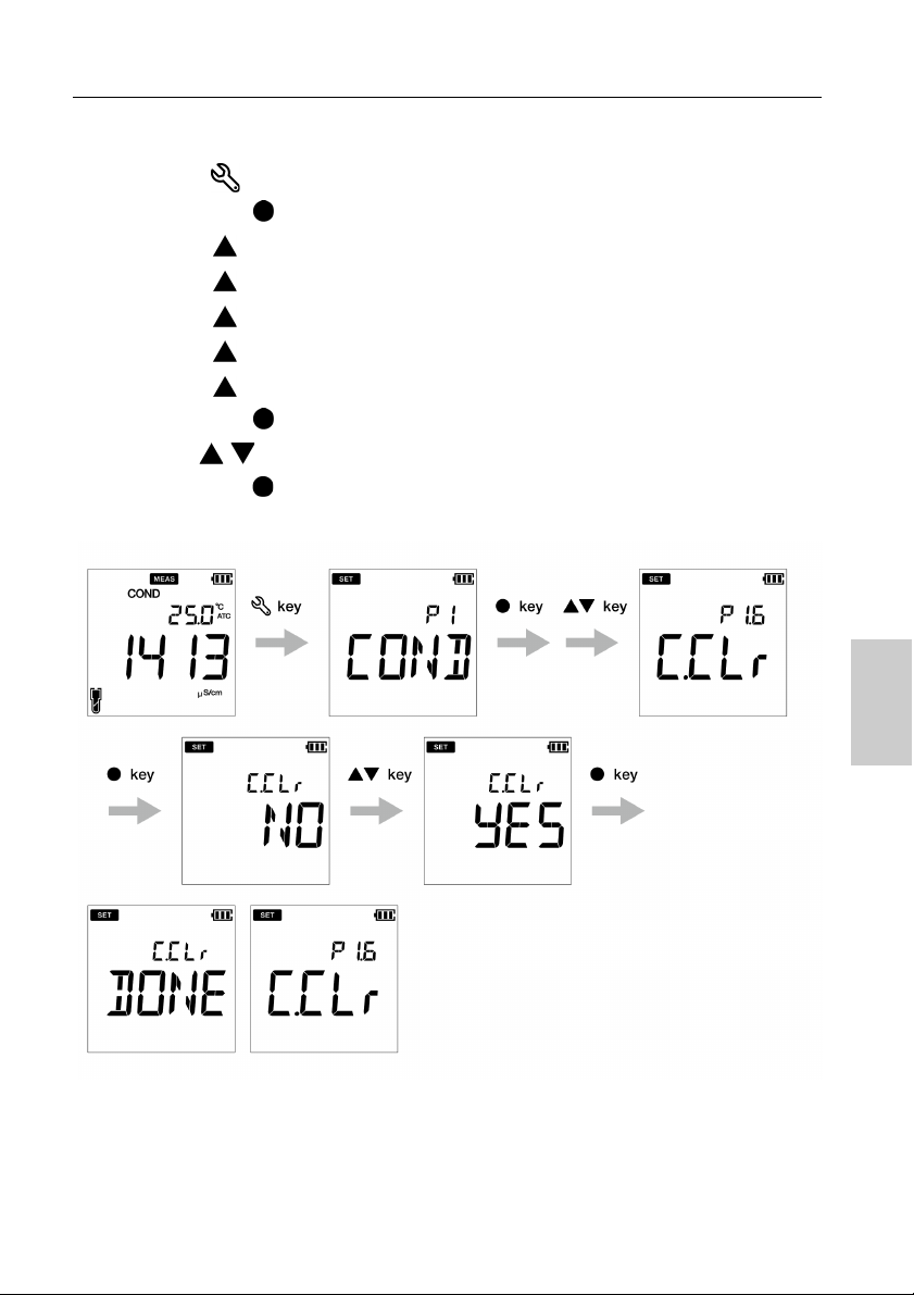
● P 1.6 Erase calibration data
1.Press the key, P1 COND screen appears.
2.Press the ENT
3.Press the key, P1.2 UNIT screen appears.
4.Press the key, P1.3 A.CAL appears.
5.Press the key, P1.4 T.CFF appears.
6.Press the key, P1.5 T.rEF appears.
7.Press the key, P1.6 C.CLr appears.
8.Press the ENT
9.Use the keys to change the setup to YES. This erases the calibration data.
10.Press the ENT
calibration data.
key, P1.1 CELL screen appears.
key, C.CLr NO screen appears with NO as default setup.
key. P1.6 C.CLr screen appears. This indicates erasure of
35
Page 50

TDS set up
Note
Tip
● P2 TDS setup
Using P2 TDS setup function of the meter, you can:
• Select TDS curve
• Select TDS unit
• Erase calibration data
To set the TDS functions using LAQUA PC200 handheld meter, follow the procedure detailed
below:
Prerequisites
Switch on the PC meter.
• Default TDS curve is linear. You can change the TDS curve to 442 or EN27888 or NaCl.
• For linear curve, default multiplier factor is FACT 0.50. You can set a multiplier factor in
between 0.40 to 1.00.
• Default TDS unit is set as mg/L (g/L). You can change the unit to ppm (ppt).
• Erasing previous calibration data is recommended for accurate calibration. Default setup is
NO but to erase the calibration data, you need to change the setup to YES.
To return to the measurement mode, press the key.
36
Page 51

TDS set up
If you choose LINR, you can select a factor from 0.40 to 1.00.
● P 2.1 TDS curve selection
1. Press the key, P1 COND screen appears.
2. Press the
3. Press the ENT
4. Press the ENT
key, P2 TDS screen appears
key, P2.1 FACT screen appears.
key, by default FACT LINR appears.
5. Use the keys to select a TDS curve and press the ENT
6. While selecting the linear curve, set a fact in between 0.40 to 1.00.
7. Press the ENT
curve setup.
key, P2.1 FACT screen appears. This indicates completion of TDS
key.
37
Page 52
TDS set up
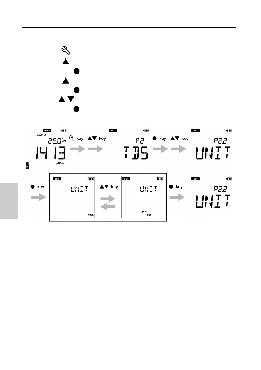
● P 2.2 Select TDS unit
1. Press the key, P1 COND screen appears.
2. Press the
3. Press the ENT
4. Press the
5. Press the ENT
6. Use the keys to change the TDS unit to ppm (ppt).
7. Press the ENT key, P2.2 UNIT screen appears. This indicates completion of TDS unit selection.
key, P2 TDS screen appears.
key, P2.1 FACT screen appears.
key, P2.2 UNIT screen appears.
key, UNIT mg/L (g/L) screen appears
38
Page 53

Salinity set up
Note
Tip
● P3 SAL setup
Using P3 SAL setups function of the meter, you can:
• Select salinity unit
• Select salinity curve
• Erase calibration data
To set the salinity functions using LAQUA PC220 handheld meter, follow the procedure detailed
below:
Prerequisites
Switch on the PC meter.
• Default salinity unit is set as ppt. You can change the unit to percentage (%).
• Default salinity type is set as NaCl. You can change the salinity type to seawater.
• Erasing previous calibration data is recommended for accurate calibration. Default setup is
NO but to erase the calibration data, you need to change the setup to YES.
To return to the measurement mode, press the key.
39
Page 54

Salinity set up
● P 3.1 select salinity unit
1. Press the key, P1 COND screen appears.
2. Press the
3. Press the
4. Press the ENT
5. Press the ENT
6. Use the keys to change the salinity unit to percentage (%).
7. Press the ENT
unit selection.
key, P2 TDS screen appears.
key, P3 SAL screen appears.
key, P3.1 UNIT screen appears.
key, by default UNIT ppt appears.
key, P3.1 UNIT screen appears. This indicates completion of salinity
40
Page 55

Salinity set up
● P 3.2 select salinity type
1. Press the key, P1 COND screen appears.
2. Press the
3. Press the
4. Press the ENT
5. Press the
6. Press the ENT
7. Use the keys to change the salinity type to seawater.
8. Press the ENT
salinity type selection.
key, P2 TDS screen appears.
key, P3 SAL screen appears.
key, P3.1 UNIT screen appears.
key, P3.2 TYPE screen appears.
key, TYPE NACL appears with NaCl as default setup.
key, P3.2 TYPE screen appears. This indicates completion of
41
Page 56

Salinity set up
● P 3.3 Erase calibration data
1. Press the key, P1 COND screen appears.
2. Press the
3. Press the
4. Press the ENT
5. Press the
6. Press the
7. Press the ENT
7. Use the keys to change the setup to YES. This erases the calibration data.
8.Press the ENT
calibration data.
key, P2 TDS screen appears.
key, P3 SAL screen appears.
key, P3.1 UNIT screen appears.
key, P3.2 TYPE screen appears.
key, P3.3 C.CLr screen appears.
key, C.CLr NO appears with NO as default setup.
key. P3.3 C.CLR screen appears. This indicates erasure of
42
Page 57

Data set up
Note
Tip
● Data setup
Using Data setup function of the meter, you can:
• Set data log interval
• Print data log
• Erase data log
To set the data functions using LAQUA PC200 handheld meter, follow the procedure detailed
below:
Prerequisites
• Switch on the PC meter.
• Keep the meter either in pH or EC mode
• Data setup procedure is common in both pH and EC mode with different meter screen
display based on available setup sequence.
• Default data log interval is ----, where ---- indicates “no data log interval” has been set.
• Data log interval can be set from 2 to 999 seconds.
To return to the measurement mode, press the key.
43
Page 58

Data set up
● Data log interval setup
1. Press the key, P1 PH/EC screen appears.
2. Press the key, P2/P4 DATA screen appears.
3. Press the ENT key, P2.1/P4.1 LOG screen appears.
4. Press the ENT key, previously set log interval appears.
5. Use the keys to set the data log interval.
6. Press the ENT key, P2.1/P4.1 LOG screen appears. This indicates completion of data log interval setup.
pH mode
44
Page 59

EC mode
Data set up
45
Page 60

Data set up
● Print data setup
1. Press the key, P1 PH/EC screen appears.
2. Press the key, P2/P4 DATA screen appears.
3. Press the ENT key, P2.1 LOG screen appears.
4. Press the key, P2.2/P4.2 PrNT screen appears.
5. Press the ENT key, default setup is NO.
6. Use the keys to change the setup to YES.
7. Press the ENT key, P2.2/P4.2 PrNT screen appears. This indicates completion of the print data.
pH mode
46
Page 61

EC mode
Data set up
47
Page 62
Data set up
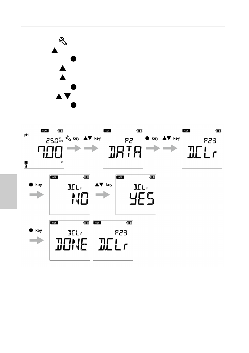
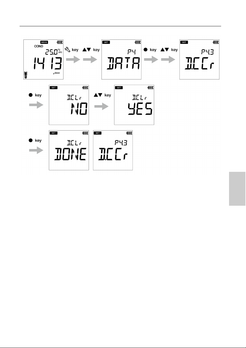
● Erase data
1. Press the key, P1 PH/EC screen appears.
2. Press key, P2/P4 DATA screen appears.
3. Press the ENT key, P2.1/P4.1 LOG screen appears.
4. Press the key, P2.2/P4.2 PRNT screen appears.
5. Press the key, P2.3/P4.3 D.CLR screen appears.
6. Press the ENT key, default setup is NO.
7. Use the keys set it to YES to erase all the data.
8. Press the ENT key, D.CLR DONE screen appears briefly and then P2.3/P4.3
D.CLR screen appears. This indicates completion of erasure of data.
pH mode
48
Page 63
EC mode
Data set up
49
Page 64
General set up
Note
Tip
● General setup
Using P3 General setup function of the meter, you can:
• Select stability mode of the meter
• Set auto shut-off time
• Select temperature measurement
• Reset the meter
To set the general functions using LAQUA PC200 handheld meter, follow the procedure
detailed below:
Prerequisites
• Switch on the PC meter.
• Keep the meter either in pH or EC mode
• General setup procedure is common in both pH and EC mode with different meter screen
display based on available setup sequence.
• In the calibration mode, the auto stable (AS) mode is activated. Default stability setup in
measurement mode is “auto stable” (AS). If you like, you can change it to “auto hold” (AH)
or “real time” (RT).
• Default auto shut-off time is 30 minutes. You can set the time from ---- to 30 minutes, where
---- indicates “no auto shut-off time” has been set and meter will be on continuously.
• Default temperature unit is °C and you can change the unit to °F.
• Default reset meter setup is NO. If you like to reset the meter, you can change it to YES.
• Stability judgment criteria remains same for both auto stability mode and auto hold mode.
• To return to the measurement mode,
press the key.
50
Page 65

General set up
● Auto Stable, Auto Hold and Real Time mode setup
Auto Stable (AS) mode - the meter shows live readings annunciator blinks until the reading
is stable.
Auto Hold (AH) mode - the meter locks the stable reading; annunciator blinks until reading is
stable and then lights up.
Real Time (RT) mode - the meter shows live readings; Both and annunciators are
inactive.
1. Press the key, P1 PH/EC screen appears.
2. Press key, P2 DATA screen appears.
3. Press key, P3/P5 GEN screen appears.
4. Press the ENT key, P3.1/P5.1 STBL screen appears.
5. Press the ENT key, Default the stability mode is AS (auto stable).
6. Use the keys to change the stability mode as AH (auto hold) or RT (real time).
7. Press the ENT key, P3.1/P5.1 STBL screen appears. This indicates completion of the stability mode selection.
pH mode
51
Page 66

General set up
EC mode
52
Page 67

General set up
Note
● Auto shut-off time setup
1. Press the key, P1 PH/EC screen appears.
2. Press the key, P2 DATA screen appears.
3. Press the key, P3/P5 GEN screen appears.
4. Press the ENT key, P3.1/P5.1 STBL screen appears.
5. Press the key, P3.2/P5.2 A.OFF screen appears.
6. Press the ENT key, default auto shut-off time is 30 minutes.
7. Use the keys to adjust the auto off time.
8. Press the ENT key, P3.2/P5.2 A.OFF screen appears. This indicates completion of the auto shut-off time setup.
The default shut off time is 30 minutes. This can be adjusted from 1 minute to 30 minutes. If
you set the display to ‘----’ it indicates Auto Off is disabled. Meter will be on indefinitely till the
user switches off the meter.
pH mode
53
Page 68

General set up
EC mode
54
Page 69

General set up
● Temperature unit setup
1. Press the key, P1 PH/EC screen appears.
2. Press the key, P2 DATA screen appears.
3. Press the key, P3/P5 GEN screen appears.
4. Press the key, P3.1/P5.1 STBL screen appears.
5. Press the key, P3.2/P5.2 A.OFF screen appears.
6. Press the key, P3.3/P5.3 °C°F screen appears.
7. Press the ENT key, default temperature unit is °C.
8. Use the keys to change the unit to °F.
9. Press the ENT key, P3.3/P5.3 °C°F screen appears. This indicates completion of the end temperature unit selection.
pH mode
55
Page 70

General set up
EC mode
56
Page 71

General set up
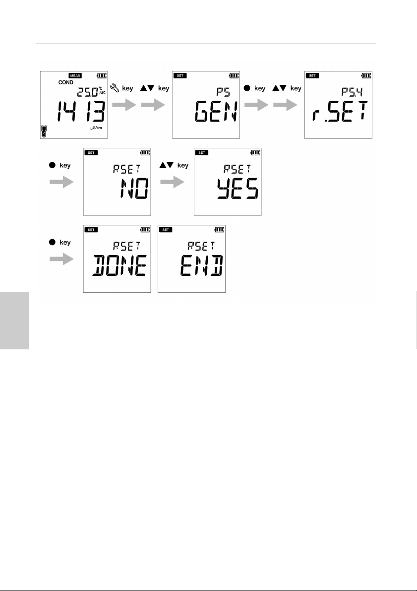
● Reset meter (factory default)
1. Press the key, P1 PH/EC screen appears.
2. Press the key, P2 DATA screen appears.
3. Press the key, P3/P5 GEN screen appears.
4. Press the ENT key, P3.1/P5.1 STBL screen appears.
5. Press the key, P3.2/P5.2 A.OFF screen appears.
6. Press the key, P3.3/P5.3 °C°F screen appears.
7. Press the key, P3.4/P5.4 r.SET screen appears.
8. Press the ENT key, default meter re-setup is NO.
9. Use the
10. Press the key. Meter displays DONE and automatically switches off.
key to set it YES.
pH mode
57
Page 72
General set up
EC mode
58
Page 73

Clock set up
Note
Tip
Tip
● CLK setup
Real-time clock functionality is available only for LAQUA 220 meters. Using P4 Clock setup
function of the meter, you can set:
• Date
• Time
To set the clock function using LAQUA PC220 handheld meter, follow the procedure detailed
below:
Prerequisites
• Switch on the PC meter.
• Keep the meter either in pH or EC mode
• Clock setup procedure is common in both pH and EC mode with different meter screen
display based on available setup sequence.
• Setup date and time is necessary before using the instrument for the first time or after
replacing the batteries.
• Set date and time data is captured correctly while saving data in the internal memory.
To return to the measurement mode, press the key.
59
Page 74
Clock set up
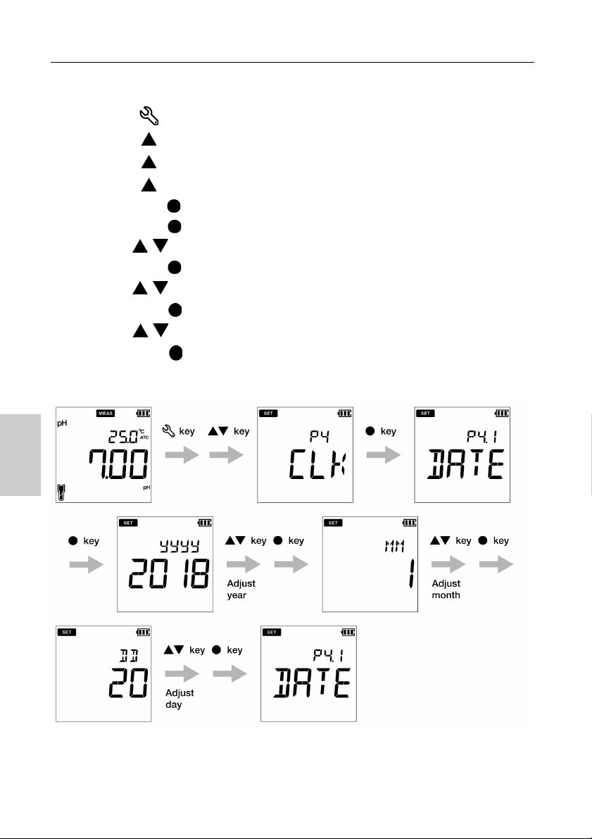
● Date setup
1. Press the key, P1 PH/EC screen appears.
2. Press the key, P2 DATA screen appears.
3. Press the key, P3 GEN screen appears.
4. Press the key, P4 CLK screen appears.
5. Press the ENT key, P4.1 DATE screen appears.
6. Press the ENT key, default set year appears.
7. Use the
8. Press the ENT key, default set month appears.
9. Use the
10. Press the ENT key, default set day appears.
11. Use the keys to adjust the day.
12. Press the ENT key, P4.1 DATE screen appears. This indicates completion of the
date setup.
keys to adjust the year,
keys to adjust the month.
pH mode
60
Page 75

EC mode
Clock set up
61
Page 76
Clock set up
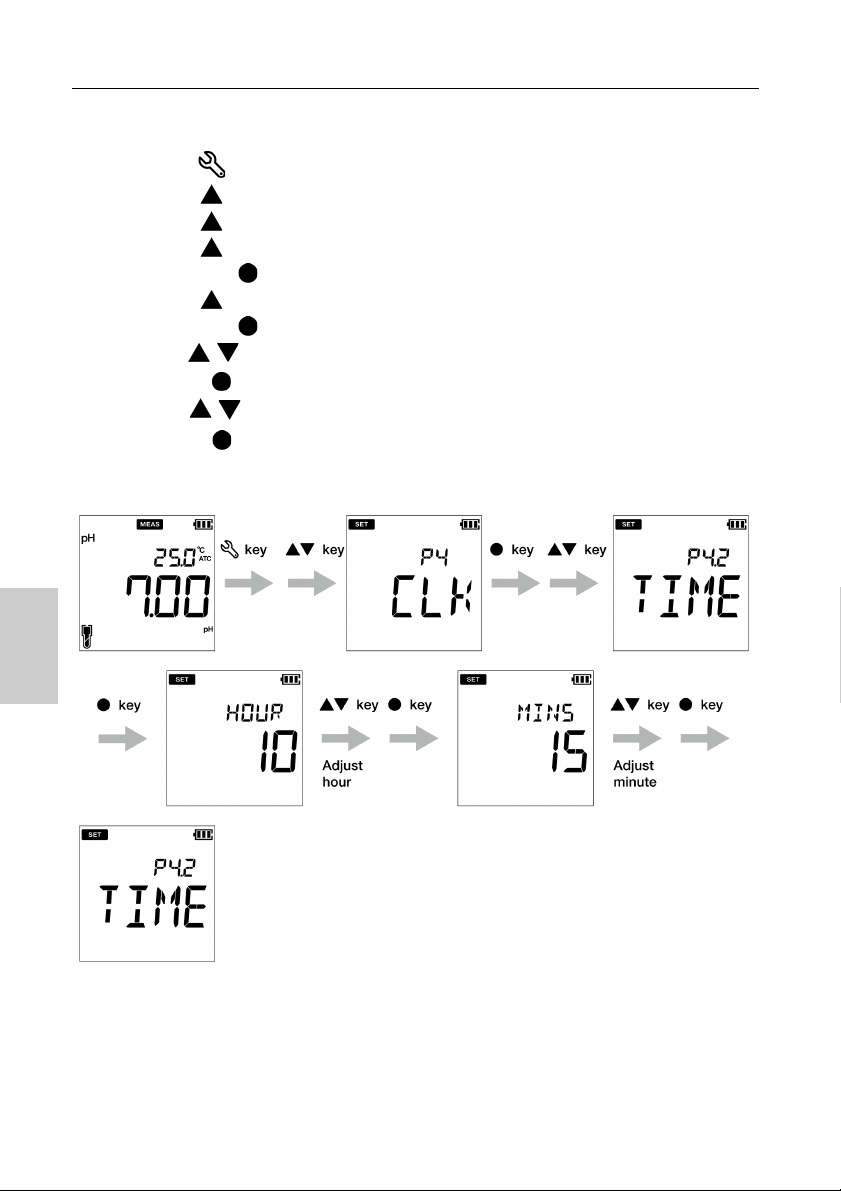
● Time setup
1. Press the key to switch to the setup mode, P1 PH/EC screen appears.
2. Press the key, P2 DATA screen appears.
3. Press the key, P3 GEN screen appears.
4. Press the key, P4 CLK screen appears.
5. Press the ENT key, P4.1 DATE screen appears.
6. Press the key, P4.2 TIME screen appears.
7. Press the ENT key, default set hour appears.
8. Use the keys to adjust the hour.
9. Press ENT key, default set minute appears.
10. Use the keys to adjust the minute.
11. P r ess ENT key, P4.2 TIME screen appears. This indicates completion of the time setup.
pH mode
62
Page 77

EC mode
Clock set up
63
Page 78

Maintenance and storage
■ Maintenance and storage
This section describes maintenance of LAQUA PC200 handheld meter, pH, ORP and
conductivity electrodes used with the meter.
● Maintenance contract
Please contact your dealer for the product maintenance contract.
● Maintenance and storage of the instrument
● How to clean the instrument
• If the instrument is dirty, wipe it gently with a soft dry cloth. If it is difficult to remove the dirt,
wipe it gently with a cloth moistened with alcohol.
•The instrument is made of solvent resistant materials but is not resistant to all
chemicals. Do not dip the instrument in strong acid or alkali solution, or wipe it with such
solutions.
• Do not wipe the instrument with polishing powder or other abrasive compound.
● Environmental conditions for storage
• Temperature: 0 °C to 45 °C
• Humidity: under 80% relative humidity and free from condensation
● Avoid the following conditions:
• Dusty place
• Strong vibration
• Direct sunlight
• Corrosive gas environment
• Close to an air-conditioner
• Direct wind
64
Page 79

Maintenance and storage
● Maintenance and storage of electrodes
This section describes an overview of the procedures for maintenance and storage of pH, ORP
and conductivity electrodes.
● How to clean the electrodes
Always clean the electrode with deionized water after every measurement. When the response
is slow or residue from the sample adheres to the electrode, use the appropriate method below
to clean the electrode, and then clean again with deionized water.
For pH electrode
Type of dirt Cleaning solution
General Diluted neutral cleaning solution
Oil Alcohol, or diluted neutral cleaning solution
Inorganic substance 1 mol/L HCl or electrode cleaning solution
Protein Cleaning solution including protein-removing enzyme
Alkali Dip in 1 mol/L HCl or electrode cleaning solution for 1h to 2 h
For ORP electrode
Type of dirt Cleaning solution
General
Oil
Inorganic substance Immerse dilute nitric acid (1:1 nitric acid)
Dilute neutral cleaning solution (General dish washing liquid
works reasonably well.)
For conductivity electrode
Type of dirt Cleaning solution
General Diluted neutral cleaning solution
Inorganic substance Ethanol (keep the ethanol away from plastic parts)
A commercially available scale remover or dilute neutral
Scale that formed during
long term storage
cleaning solution. If this does not remove the scale, use diluted
solution that contains oxygen bleach (sodium percarbonate) or
chlorine bleach (sodium hypochlorite).
65
Page 80

Maintenance and storage
● Daily storage of the pH and ORP electrodes
If the electrode becomes dry, the response will be slow. Store in a moist atmosphere. Follow
the steps below to properly store the electrodes even when the electrodes will not be used for a
long period.
1. Wash the electrode well with pure water (or deionized water) to remove sample completely, and close the internal solution filler port.
2. Wash the inside of the protective cap with pure water (or deionized water), then add enough pure water (or deionized water) to soak the sponge.
3. Attach the protective cap.
● Daily storage of the conductivity electrode
If the electrode is stored in a dry state, the cell constant will change. Store with the black
electrode part immersed in deionized water, or with the protective cap filled with deionized
water and attached to the electrode.
To store the electrode for a long period, clean it well and attach the protective cap filled with
deionized water.
66
Page 81

Error mess ages and t rouble shoot ing
■ Error messages and trouble shooting
● Error message
This section describes the causes of typical errors and the actions to be taken to resolve
respective errors.
If ERR is displayed while you are using the instrument, check the error, its cause and action to
be taken in the error list below:
Meter display ERR description Cause of error
and
How to solve the problem
BATT LOW Low battery
OFFS ERR Offset voltage error
SLPE ERR Slope error
Can not auto
BUFF ERR
recognize standard
solution
Battery power is low. Please replace with new
batteries.
Electrode is dirty or reference junction is
clogged. Clean the electrode.
Electrode sensitivity is low. Please clean and
recalibrate with fresh standard solution. If the
problem persists, replace the electrode with
new one.
The instrument cannot identify the standard
solution. Check the calibration solution and
use fresh one if required.
Calibration interval
alarm error
MEM FULL Memory data full
If user selects the
enter key before stable
in calibration mode
Exceeds the calibration interval setup.
Calibrate the meter.
The number of the data saved has exceeded
the specified number of items. Print or
transfer the data. Or, clear stored data.
key is pressed before the calibration
value has stabilized. Wait for the value to be
stable and then press the key.
67
Page 82

Error messages and trouble shooting
● Trouble shooting
This section describes causes and actions to take for problems that customers frequently ask.
The indicated value fluctuates
< Problem with the electrode >
Cause How to solve problem
The electrode is dirty. Clean the electrode.
The electrode is cracked. Replace the electrode.
The level of reference electrolyte gel. Replace the electrode.
< Problem with the instrument >
Cause How to solve problem
There is a motor or other device
causing electrical interference.
The electrode is not connected
correctly.
< Problem with the sample >
Cause How to solve problem
Electrode is not immersed enough to
cover liquid junction.
The stability of electrode is affected by
the sample solution.
68
Measure at a place where no influence from induction
is given. Ground all AC-powered equipment.
Connect the electrode properly.
The electrode must be immersed up to the liquid
junction.
As a guide, immerse to at least 3 cm from the tip of
the electrode.
It is important to select an electrode that is
appropriate for the sample. Consult your dealer. To
confirm an electrode that is appropriate for the
sample, check the electrode selection guide in our
catalogue, or refer to our website.
Page 83

Error mess ages and t rouble shoot ing
The response is slow
Cause How to solve problem
The electrode is dirty. Clean the electrode.
The electrode is cracked. Replace the electrode.
It is important to select an electrode that is
The response of electrode is affected
by the sample solution.
The indicated value does not change/No response
appropriate for the sample. Consult your dealer. To
confirm an electrode that is appropriate for the
sample, check the electrode selection guide in our
catalogue, or refer to our website.
Cause How to solve problem
The electrode is cracked. Replace the electrode.
The electrode is not connected
correctly.
Keys are locked.
The instrument is in HOLD state. Cancel the HOLD state.
Instrument defect Consult your dealer.
Connect the electrode correctly.
Turn OFF the power, remove the batteries, and then
turn ON the power again.
69
Page 84

Error messages and trouble shooting
The measured value is out of the measurement range
When the measured value is below the display range, “Ur” appears. When the measured value
is over the display range, “Or” appears.
Cause How to solve problem
Sample is out of the measurement
range.
Electrode is not immersed enough to
cover liquid junction.
The electrode cable is broken. Replace the electrode.
Calibration is not performed or
performed incorrectly.
Instrument defect Check as explained below.
Use a sample within the measurement range.
The electrode must be immersed up to the liquid
junction.
As a guide, immerse to at least 3 cm from the tip of
the electrode.
Perform calibration correctly.
● How to chec k for instr ument def ect (pH m ode)
Short the metal part of the outer tube to the center pin of the electrode
connector of the corresponding channel of the instrument. If “Ur” or “Or”
appears in this condition, consult your dealer.
Repeatability of the measured value is poor
Cause How to solve problem
Effect of the sample solution
Repeatability becomes poor when the pH of the sample
changes over time.
The electrode is dirty. Clean the electrode.
The electrode is cracked. Replace the electrode.
The internal solution of the
electrode is partially depleted or
contaminated.
Replace the electrode.
70
Page 85

Error mess ages and t rouble shoot ing
Nothing appears when the power is turned ON
Cause How to solve problem
Power is not supplied. Insert batteries or connect the AC adapter (option).
Battery polarity (+, ) is reversed. Insert the batteries with the polarity (+, ) correctly oriented.
Battery life is low. Replace the batteries.
Instrument defect Consult your dealer.
Swelling of keypad
Cause How to solve problem
Using the instrument at high
elevation or other location where
the air pressure is different from
sea level.
Instrument defect Consult your dealer.
Part of the display is missing
To eliminate the pressure difference between the inside and
outside of the instrument, briefly open and then close the
serial connector and battery cover. After opening, correctly
close the cover to maintain dust and water proofing.
Cause How to solve problem
Instrument defect
Check the display by switching ON the instrument when all
the LCD segments are lit.
71
Page 86

Technical note
■ Appendix
● Appendix 1
This section describes technical information and option for LAQUA PC200 handheld meters.
The pH vs. temperature values for the various standards are listed below:
< USA >
Tem p . (° C ) pH 1.68 pH 4.01 pH 7.00 pH 10.01 pH 12.46
0 1.67 4.01 7.12 10.32
5 1.67 4.01 7.09 10.25 13.25
10 1.67 4.00 7.06 10.18 13.03
15 1.67 4.00 7.04 10.12
20 1.68 4.00 7.02 10.06 12.64
25 1.68 4.01 7.000 10.01 12.46
30 1.69 4.01 6.98 9.97 12.29
35 1.69 4.02 6.98 9.93
40 1.70 4.03 6.97 9.89 11.99
45 1.70 4.04 6.97 9.86
50 1.71 4.06 6.97 9.83 11.73
55 1.72 4.08 6.97 9.81
72
Page 87

Technical note
< NIST >
Tem p . (° C ) pH 1.68 pH 4.01 pH 6.86 pH 9.18 pH 12.46
0 1.67 4.00 6.98 9.46
5 1.67 4.00 6.95 9.39 13.25
10 1.67 4.00 6.92 9.33 13.03
15 1.67 4.00 6.90 9.27
20 1.68 4.00 6.88 9.22 12.64
25 1.68 4.01 6.86 9.18 12.46
30 1.69 4.01 6.85 9.14 12.29
35 1.69 4.02 6.84 9.10
40 1.70 4.03 6.84 9.04 11.99
45 1.70 4.04 6.83 9.04
50 1.71 4.06 6.83 9.01 11.73
55 1.72 4.08 6.83 8.99
< DIN >
Tem p . (° C ) pH 1.09 pH 3.06 pH 4.65 pH 9.23 pH 12.75
0 1.08 3.10 4.67 9.48 13.37
5 1.09 3.10 4.66 9.43 13.37
10 1.09 3.10 4.66 9.37 13.37
15 1.09 3.08 4.65 9.32 13.17
20 1.09 3.07 4.65 9.27 12.96
25 1.09 3.06 4.65 9.23 12.75
30 1.10 3.05 4.65 9.18 12.61
35 1.10 3.04 4.65 9.13 12.45
40 1.10 3.04 4.66 9.09 12.29
45 1.11 3.04 4.67 9.04 12.14
50 1.11 3.04 4.68 9.00 11.98
55 1.11 3.04 4.69 8.96 11.84
73
Page 88
Technical note
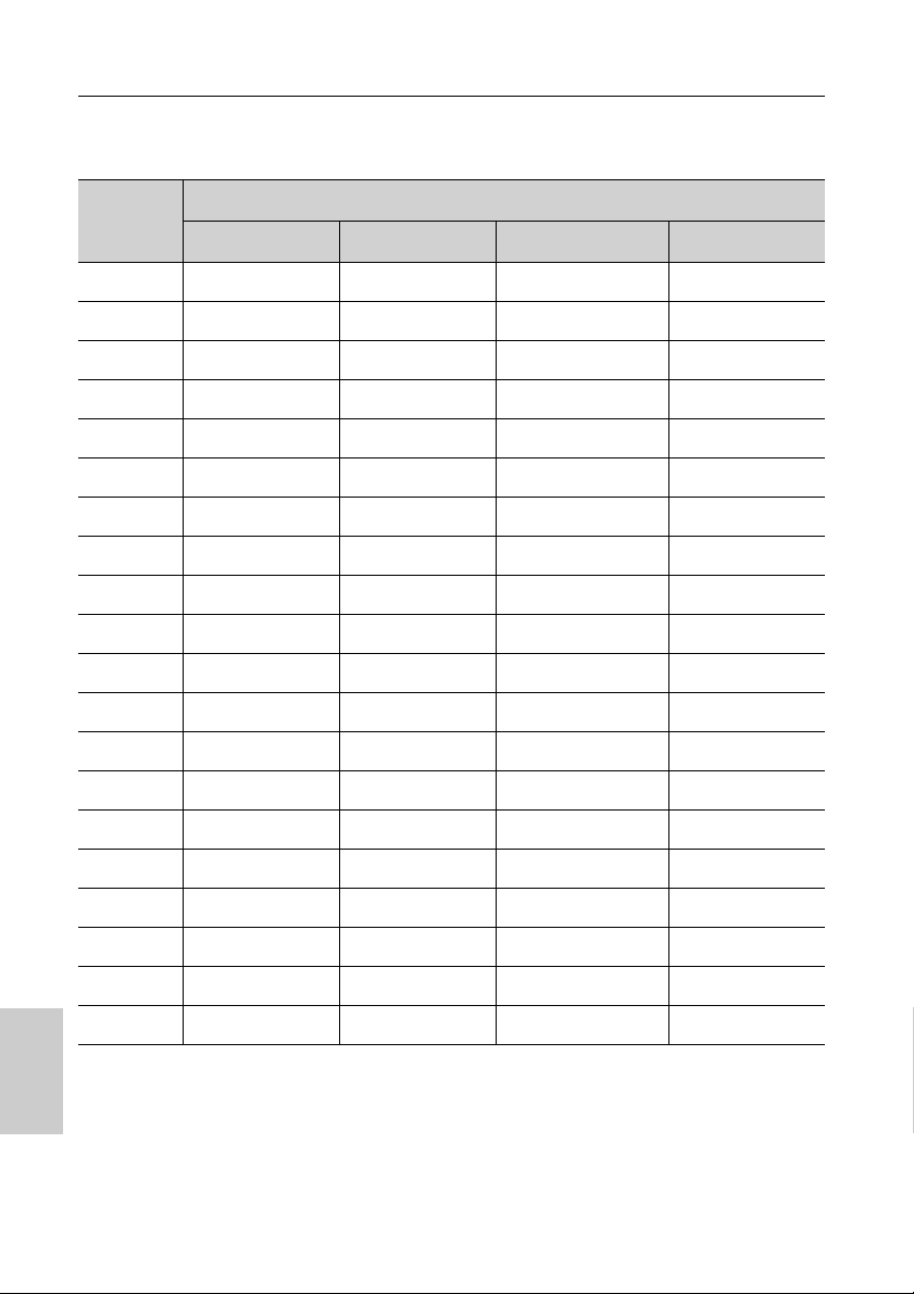
● Conductivity standard values at various temperatures
Tem p.
(°C)
0 64.01 776 7.15 65.4
5 65.00 896 8.22 74.1
10 67.00 1020 9.33 83.2
15 68.00 1147 10.48 92.5
16 70.00 1173 10.72 94.4
17 71.00 1199 10.95 96.3
18 73.00 1225 11.19 98.2
19 74.00 1251 11.43 100.2
20 76.00 1278 11.67 102.1
21 78.00 1305 11.91 104.0
22 79.00 1332 12.15 105.9
23 81.00 1359 12.39 107.9
24 82.00 1386 12.64 109.8
25 84.00 1413 12.88 111.8
26 86.00 1440 13.13 113.8
84.00 (S/cm) 1413 (S/cm) 12.88 (mS/cm) 111.8 (mS/cm )
Conductivity value at 25 °C
27 87.00 1467 13.37 115.7
28 89.00 1494 13.62 117.7
29 90.00 1521 13.87 119.7
30 92.00 1548 14.12 121.8
31 94.00 1575 14.37 123.9
74
Page 89

● Appendix 2
Printout summary
pH
Meter Model : HORIBA PC220
Serial Number : 123456789
SW Revision : 1.00
Date : 20 Aug 2018
Time : 10:10:28
Mode : pH
pH : 7.00 pH
mV : 0.0 mV
Temperature : 25.0 C (MAN)
Electrode Status : Excellent
User Name :
Signature :
mV
Meter Model : HORIBA PC220
Serial Number : 123456789
SW Revision : 1.00
Date : 20 Aug 2018
Time : 10:10:28
Mode : mV
mV : 0.0 mV
Temperature : 25.0 C (MAN)
User Name :
Signature :
Printer format - Measurement
74
Page 90

Printout summary
Relative mV
Meter Model : HORIBA PC220
Serial Number : 123456789
SW Revision : 1.00
Date : 20 Aug 2018
Time : 10:10:28
Mode : R. mV
R. mV : 3.0 mV
Offset : -3.0 mV
Temperature : 25.0 C (MAN)
User Name :
Signature :
Conductivity
Meter Model : HORIBA PC220
Serial Number : 123456789
SW Revision : 1.00
Date : 20 Aug 2018
Time : 10:10:28
Mode : Conductivity
Cond : 1413 us/cm
Temperature : 25.0 C (MAN)
Electrode Status : Excellent
User Name :
Signature :
75
Page 91

Printout summary
Resistivity
Meter Model : HORIBA PC220
Serial Number : 123456789
SW Revision : 1.00
Date : 20 Aug 2018
Time : 10:10:28
Mode : Resistivity
Resistivity : 1000 M-Ohm/cm
Temperature : 25.0 C (MAN)
Electrode Status :
User Name :
Signature :
Salinity
Meter Model : HORIBA PC220
Serial Number : 123456789
SW Revision : 1.00
Date : 20 Aug 2018
Time : 10:10:28
Mode : Salinity
Salinity : 50.0 ppt
Temperature : 25.0 C (MAN)
Electrode Status : Excellent
User Name :
Signature :
76
Page 92

Printout summary
TDS
Meter Model : HORIBA PC220
Serial Number : 123456789
SW Revision : 1.00
Date : 20 Aug 2018
Time : 10:10:28
Mode : TDS
TDS : 1.23 g/L
Temperature : 25.0 C (MAN)
Electrode Status :
User Name :
Signature :
Meter Model : HORIBA PC220
Serial Number : 123456789
SW Revision : 1.00
User Name :
Signature :
Logged Data
Location : 2
Date : 10 Aug 2018
Time : 10:10:28
Mode : pH
pH : 7.00 pH
mV : 0.0 mV
Temperature : 25.0 C (MAN)
Electrode Status : Excellent
Location : 1
Date : 10 Aug 2018
Time : 10:09:28
Mode : mV
mV : 178.0 mV
Temperature : 25.0 C (MAN)
Printer format - Data log
77
Page 93

Printout summary
PH
Meter Model : HORIBA PC220
Serial Number : 123456789
SW Revision : 1.00
Date : 20 Aug 2018
Time : 10:10:28
Calibration data
Cal Date : 20 Jun 2018
Cal Time : 10:10:10
Cal Points : 4.01, 7.00, 10.01
Offset : 0.0 mV
Avg Slope : 98.2 %
Cal Temp. : 25.0 C (ATC)
Electrode Status : Excellent
User Name :
Signature :
EC
Meter Model :HORIBA PC220
Serial Number :123456789
SW Revision :1.00
Date :20 Aug 2018
Time :10:10:28
Calibration data
Cal Date :20 Jun 2018
Cal Time :10:10:10
Cal Points :84.0 uS. 1413 uS
Avg Cal Factor :1.022
Cal Temp. :25.0 C (ATC)
Electrode Status :Excellent
User Name :
Signature :
Printer format - Calibration
78
Page 94

Specifications
● Appendix 3
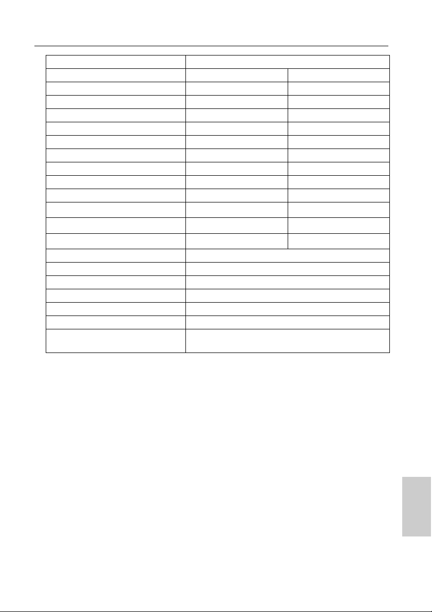
Model
pH Range -2.00 to 16.00 pH
Resolution 0.01 pH
Accuracy ±0.01 pH
Calibration Points USA & NIST (Up to 5), DIN (Up to 6)
pH Buffer Groups USA, NIST, DIN
ORP Range ±2000 mV
Resolution 0.1 mV (˂ ±1000 mV), 1 mV (≥ ±1000mV)
Accuracy ±0.3 mV (˂ ±1000 mV), 0.3% of reading (≥ ±1000mV)
Calibration Option Yes
Conductivity Range µS/cm to 200.0 mS/cm (k=1.0)
Resolution 0.05% full scale
Accuracy ±0.6% full scale, ±1.5% full scale > 18.0 mS/cm
Reference Temperature 15 to 30 °C (adjustable)
Temperature Coefficient 0.00 to 10.00 %/°C
Cell Constants 0.1, 1.0, 10.0
Calibration Points Up to 4 (Auto) / Up to 5 (Manual)
Units S/cm, S/m (Auto Ranging)
Total Dissolved Solids (TDS) Range ppm to 100 ppt (TDS factor=0.5)
Resolution 0.01 ppm (mg/L) / 0.1 ppt (g/L)
Accuracy ±0.1% full scale
TDS Curves Linear (0.40 to 1.00), EN27888, 442, NaCl
Resistivity Range 0.000 Ω•cm to 20.0 MΩ•cm
Resolution 0.05% full scale
Accuracy
Salinity Range 0.0 to 100.0 ppt / 0.00 to 10.00 %
Resolution 0.1 ppt / 0.01%
Accuracy ±0.2% full scale
Salinity Curves NaCl, Seawater
Calibration Option Yes
Temperature Range -30.0 to 130.0 °C / -22.0 to 266.0 °F
Resolution 0.1 °C / °F
Accuracy ± 0.5 °C / ± 0.9 °F
PC210 PC220
pH/ORP/EC/TDS/Sal/Res/Temp (°C/°F)
±0.6% full scale,
±1.5% full scale > 1.80 MΩ•cm
74
Page 95
Specifications
Calibration Option Yes
Memory 500 1000
Auto Data Log
Real-time Clock -
Date & Time Stamp -
Auto Hold / Auto Stable / Real Time
Offset & Average Slope Display
Calibration Alarm (1 to 90 days)
Auto Shut-Off (1 to 30 mins.)
Electrode Status
Diagnostic Messages
Software Upgrade
PC Communication
Printer Communication
*1
*1
*2
Meter Inputs BNC, phono
Display Custom LCD with backlight
Housing IP67, shock & scratch resistant, non-slip
Power Requirement 2 × AA batteries
Battery Life > 500 hours
Dimensions 160 (L) × 80 (W) × 40.60 (H) mm
Weight
-
-
Approx. 260 g (with batteries) /
216 g (without batteries)
* Meter kit with NIST pH buffers is available upon request. Add 'N' suffix to order code.
*1 Via PC (USB) cable PN 3200779639
*2 Via Printer (RS232) cable PN 3200779638
75
Page 96

Specifications
76
Page 97

31, Miyanonishi-cho, Kisshoin Minami-ku, Kyoto 601-8306, Japan
http://www.horiba-adt.jp
For any questions regarding this product, please contact your local agency, or inquire from
the following website.
http://global.horiba.com/contact_e/index.htm
Page 98

 Loading...