

Page 1

FEXL7344_7406EVA_startguide-02
ML7344, ML7406EVA
Start Guide
Issue Date: May 8, 2014
Page 2

Page 3

ML7344, 7406EVA Start Guide
NOTES
No copying or reproducti on of this docum ent, in part or i n whole, is permitte d without the c onsent of LA PIS Sem iconductor C o., Ltd.
The content specified herein is subject to change for improvement without notice.
Examples of application circuits, circuit constants and any other information contained herein illustrate the standard usage and
operations of the Products. The peripheral condit ions must be taken into account when designing circuits for mass production.
Great care was taken in ensuring the accuracy of the information specified in this document. However, should you incur any damage
arising from any inaccuracy or mi sprint of such information, LAPIS Semiconductor shall bear no responsibility for such damage.
The technical information sp ecified herei n is intend ed onl y to show the typical fun cti on s of and examples o f app li catio n circuits fo r
the Products. LA PIS Sem iconduc tor d oes no t gra nt you, e xplic itly or im plicitly, a ny licens e to use or ex erc ise intelle ctual prope rty or
other rights held by LAPIS Semiconductor and other parties. LAPIS Semiconductor shall bear no responsibility whatsoever for any
dispute arising from the use of such technical information.
The Products specified in th is document are intended to be used with general-u se electronic equipment or devices (such as audio
visual equipment, o ffice-automation equipment, communication devices, electronic appliances and amusement devices).
The Products specified in this document are not designed to be radiation tolerant.
While LAPIS Semiconductor always makes efforts to enhance the quality and reliability of its Products, a Product may fail or
malfunction for a variety of reasons.
Please be sure to im ple m e nt in your equipment using the Pro duc ts safety measures to gua rd a g ainst the possibility of physical injury,
fire or any other damage caused in the event of the failure of any Product, such as derating, redundancy, fire control and fail-safe
designs. LAPIS Sem ic onduct or sha ll bear no res ponsi bility w hats oever f or your us e of a ny Product outside of the pre scr ibed s cop e or
not in accordance with the i nstruction manual.
The Products are not designed or manufactured to be used with any equipment, device or system which requires an extremely high
level of reliability the f ailure or m alf unction of whic h m ay result in a dire ct t hreat to hum an lif e or cre ate a risk of hum an injury (such
as a medical instrument, transportation equipment, aerospace machinery, nuclear-reacto r controller, fuel-controller or other safety
device). LAPIS Semiconductor shall bear no responsibility in any way for use of any of the Products for the above special purposes.
If a Product is intended to be used for any such special purpose, please contact a ROHM sales repres entative before purchasin g.
If you intend to export or ship overseas any Product or technology specified herein that may be controlled under the Foreign
Exchange and the Foreign Trade Law, you will be required to obtain a license or permit under the Law.
Copyright 2013 - 2014 LAPIS Semiconductor Co., Ltd.
FEXL7344_7406EVA_startguide-02 i
Page 4

ML7344, 7406EVA Start Guide
Introduction
Thank you very much for purchasing products of our company. Before using this product, please use correctly after
reading this “start guide”. Moreover, please keep it caref ully even after reading this. This start guide in dicates enclosure
attachment ant the connection method.
The manual shown in the following other than this document is prepared. Please check if needed.
Datasheet
Design Guide
Simple MAC User’s Manual
FEXL7344_7406EVA_startguide-02 ii
Page 5
ML7344, 7406EVA Start Guide
1. Attention on the handling of this product
This product is evaluation kit. It is available for evaluation only.
Any responsibility cannot be taken about building this product into other products.
Please use the application software of this product with the PC with which Japanese version Windows XP is
installed.
It will become infringement of copyright, if all or apart of software of this product is reproduced without
permission of copyright or duplicate things are distributed.
Any responsibility cannot be taken about reconstruction and illegal use of this product.
If the example of a harmful electric wave interference should occur from this product, please change
operating frequency promptly, or suspend the output of an electric wave, and perform disposal for
interference evasion etc.
2. Setup Flow
Please check when open the box and all the following articles are assembled first. If it should run short or should have
damaged, please inform a purchasing agency.
CD-ROM is packed only when first time purchase.
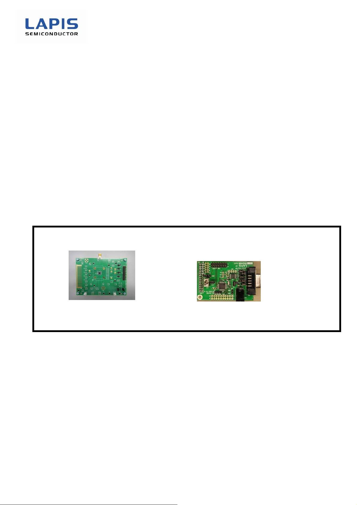
By shipment time, mounting parts etc may differ from a photograph in part.
Please prepare a stabilized power supply, a RS-232C cable (straight), and serial communication software
(TeraTerm).
- ML7344/ML7406 Evaluation Board… 1
- Power Supply Cable… 1
- CD-ROM… 1 (First time purchase only)
- ML7344, ML7406 Control Board… 1
FEXL7344_7406EVA_startguide-02 1
Page 6
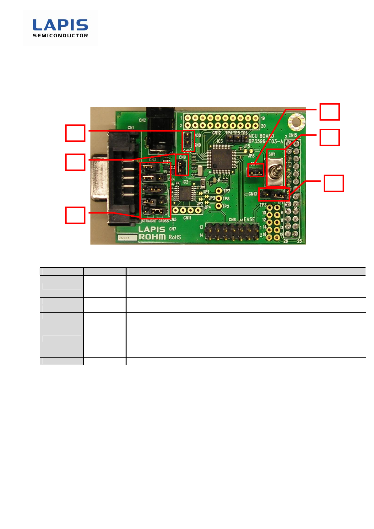
2.1. Control Board Setting
his section describes the control board setting.
T
ML7344, 7406EVA Start Guide
Number Symbol Function
SW1
CN14
CN9
CN10
CN13
CN3 – CN7
Figure 1: Control Board O verview
Table 1: Detailed Description of Control Board
In case of CN14 short,
SW1 switch is set to CN13 side (lower side in Fig.16) : set CPU reset
SW1 switch is set to “SW1” silk (upper side in Fig.16) : release CPU reset
Connect RESET pin of ML610Q482 and SW1
Short CN9 in case of the external 5.0V power supply.
If 3.0V voltage supplied by the external power supply. Please usually use open.
Change voltage supplied line on control board.
1-2 short (right side in Fig.16) : connect voltage supplied line to evaluation board.
Please usually use it in this setting.
2-3 short (left side in Fig.16) : connect voltage supplied line to CN8 (μEASE)
Open : voltage supplied by CN2 or CN8
RS232-C interfaces are set.
FEXL7344_7406EVA_startguide-02 2
Page 7
2.2. ML7344, ML7406 Evaluation Board Setting Procedure
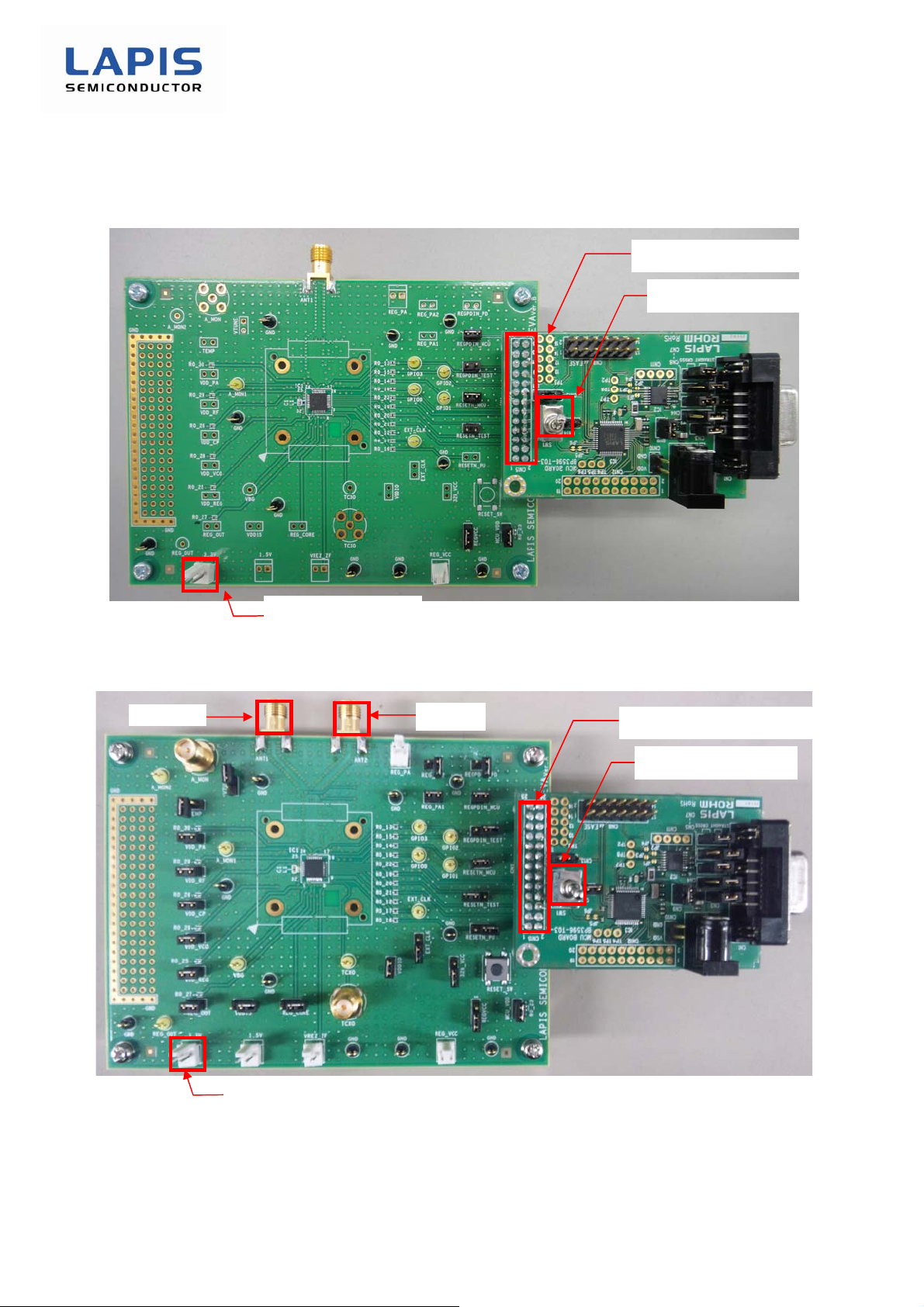
he ML7344 evaluation board is connected with the control board as shown below.
T
ML7344, 7406EVA Start Guide
Connect by 26pin connecter
SW1 Reset Switch
Supply 3.3V power
Figure 2: ML7344 Evaluation Board Connection Overview
The ML7406 evaluation board is connected with the control board as shown below.
ANT2
Connect by 26pin connecter
SW1 Reset Switch
Supply 3.3V power
Figure 3: ML7406 Evaluation Board Connection Overview
* When you do not use DIVERSITY, please use ANT1.
FEXL7344_7406EVA_startguide-02 3
Page 8
ML7344, 7406EVA Start Guide
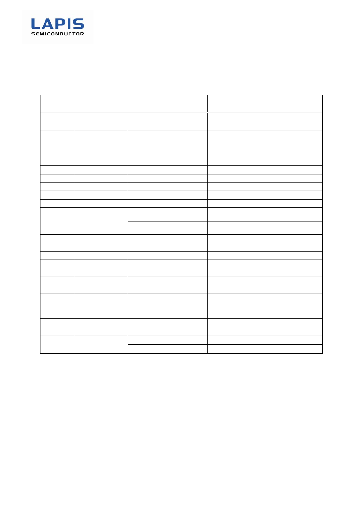
ML7344 and ML7406 evaluation board jumper function and recommended setting are as following.
Table 2: Evaluation board jumper setting table
JP No. Silk Jumper Setting Remarks
JP1 RESETN_MCU short For micro controller
JP2 REGPDIN_MCU short For micro controller
1-2short
JP3 REGVCC
2-3short
JP4 32k_VCC open
JP5 EXT_CLK open
JP101 RESETN_TEST open For test in Lapis
JP102 REGPDIN_TEST open For test in Lapis
JP103 REGPDIN_PD open
JP104 RESETN_PU open
short
JP105 MCU_VDD
open
JP106 VDDIO short ML7344’s board uses 0 Ohm.
JP107 VDD_REG short ML7344’s board uses 0 Ohm.
JP108 REG_CORE open
JP109 VDD15 open
JP110 VDD_CP short ML7344’s board uses 0 Ohm.
JP111 REG_OUT short ML7344’s board uses 0 Ohm.
JP112 VDD_VCO short ML7344’s board uses 0 Ohm.
JP113 VDD_RF short ML7344’s board uses 0 Ohm.
JP114 VDD_PA short ML7344’s board uses 0 Ohm.
JP115 REG_PA1 short ML7344’s board uses 0 Ohm.
JP116 REG_PA2 open
JP117 TEMP open
JP118 VTUNE
short(ML7344)
open(ML7406)
TCXO internal power supply
(3.3V)
TCXO external power supply
(REG_VCC)
Micro controller internal power supply
(3.3V)
Micro controller external power supply
(AC connecter on micro controller board)
FEXL7344_7406EVA_startguide-02 4
Page 9
2.3. Terminal Setting
2.3.1
. Tera Term Setting
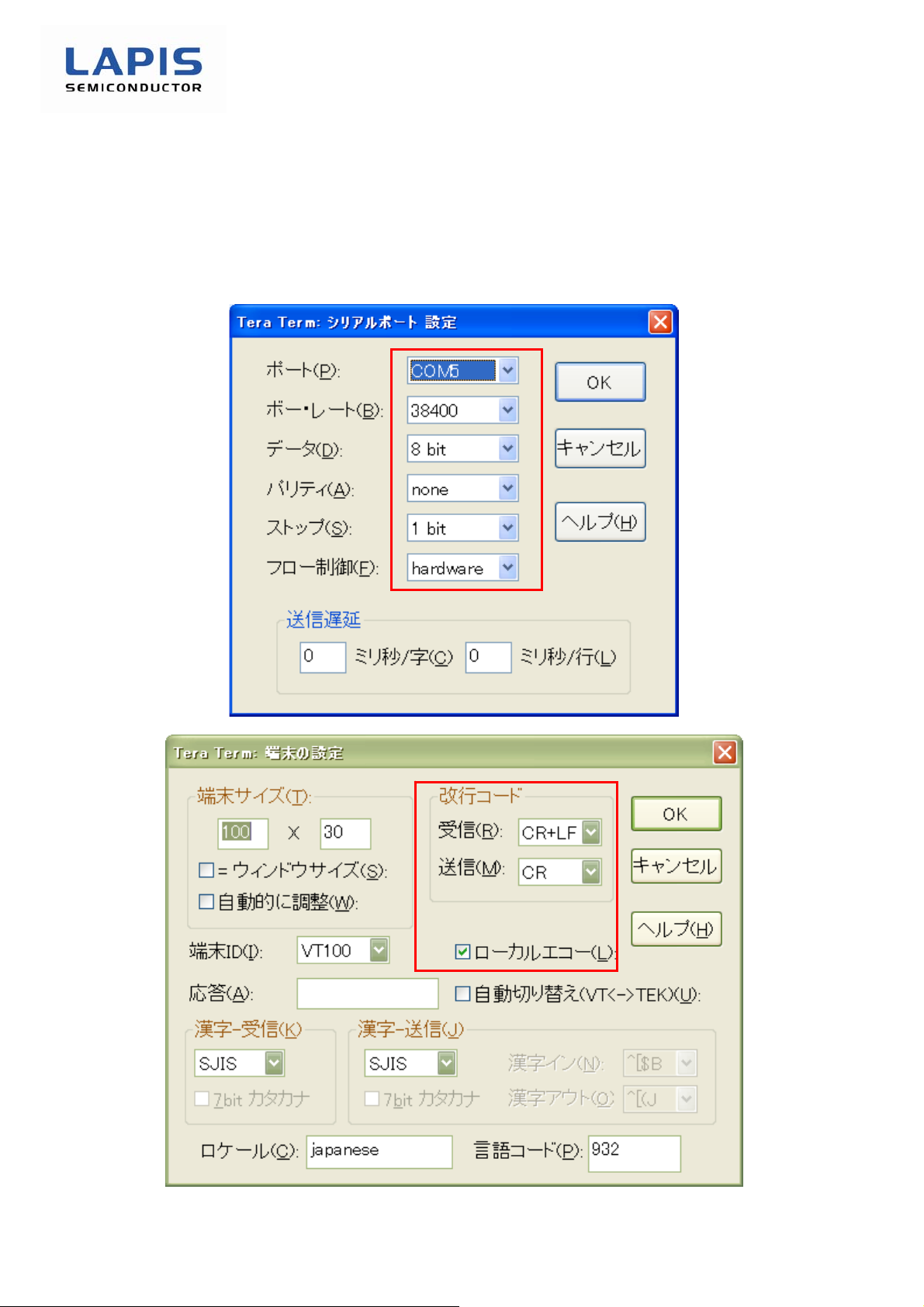
The Tera Term serial port settings are shown below.
The red frame indicates required settings. Use Tera Term version 4.63 or higher.
ML7344, 7406EVA Start Guide
Figure 4: Tera Term Serial Port Setting Screen
Figure 5: Tera Term Terminal Setting Screen
FEXL7344_7406EVA_startguide-02 5
Page 10
ML7344, 7406EVA Start Guide
2.3.2. Wireless Control Tool Setting
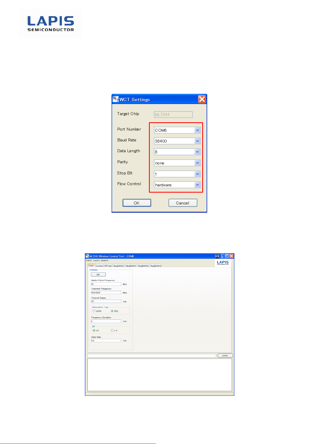
Wireless Control Tool (WCT) is able to control ML7344, ML7406 Simple MAC. WCT serial port setting
is below. You must set category in red box.
Figure 6: WCT serial port setting
If you push OK button on WCT serial port setting window, WCT main window is popd up. You can set
verification command in Init tab, Contro tab, RFTest tab, RegBANK0 tab, RegBANK1 tab, RegBANK2
tab or RegBANK3 tab. Please refer to “ML7344, ML7406 Wireless Control Tool User’s manual”.
Figure 7: WCT main window
FEXL7344_7406EVA_startguide-02 6
Page 11
ML7344, 7406EVA Start Guide
3. Connection verification procedure
Supply 3.3V power supply.
Reset the control board.
Start the terminal software (Tera Term).
Set the terminal software. (For terminal settings, refer to "2.3 Terminal Setting".)
*
No prompt will be displayed by power-on, terminal software setting, or reset.
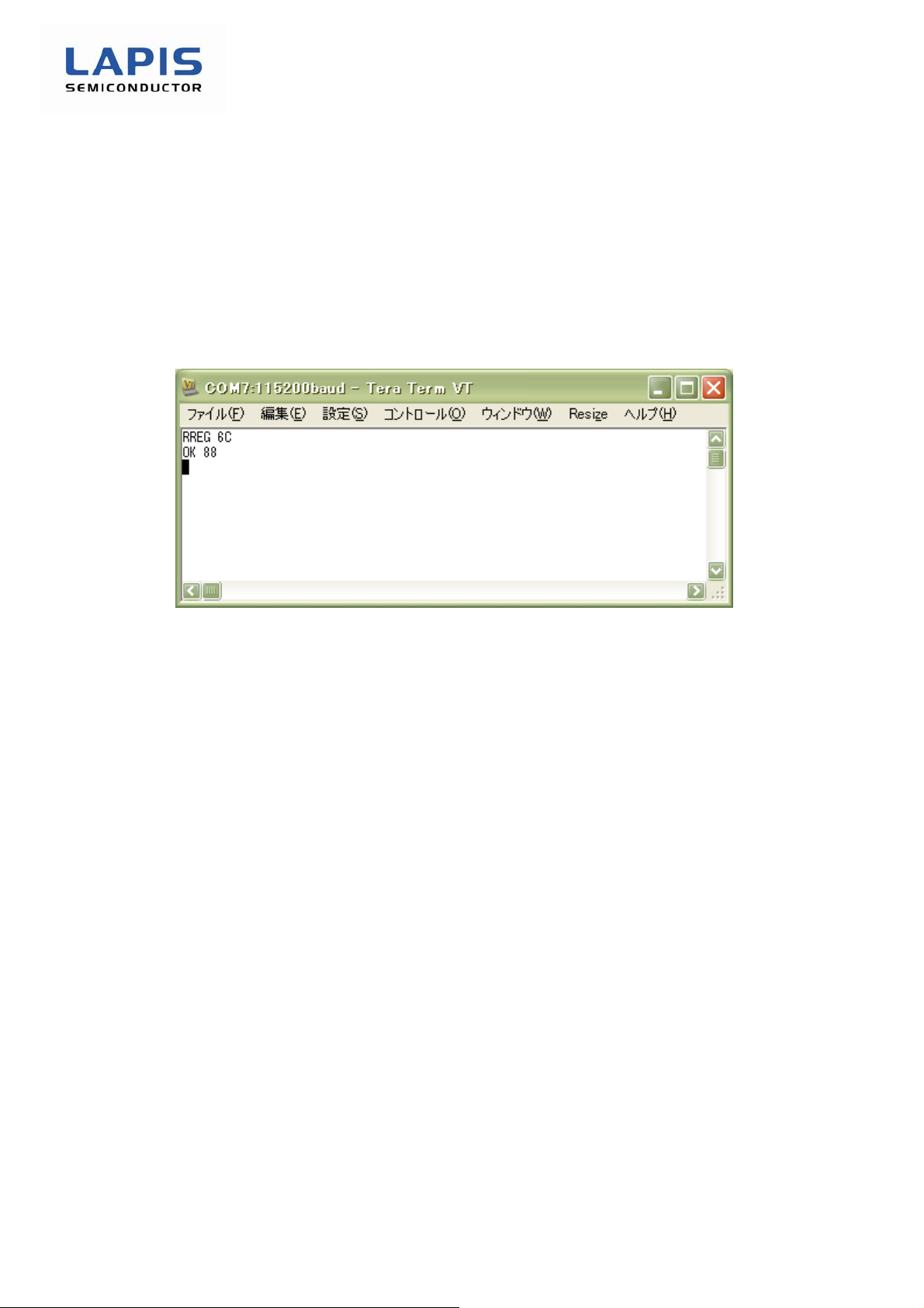
Verify the connection by a register read command. The connection is correct if confirm of “88” is
displayed in response to the read command “RREG 0B”.
Figure 8: Connection Confirmation Image
FEXL7344_7406EVA_startguide-02 7
Page 12
ML7344, 7406EVA Start Guide
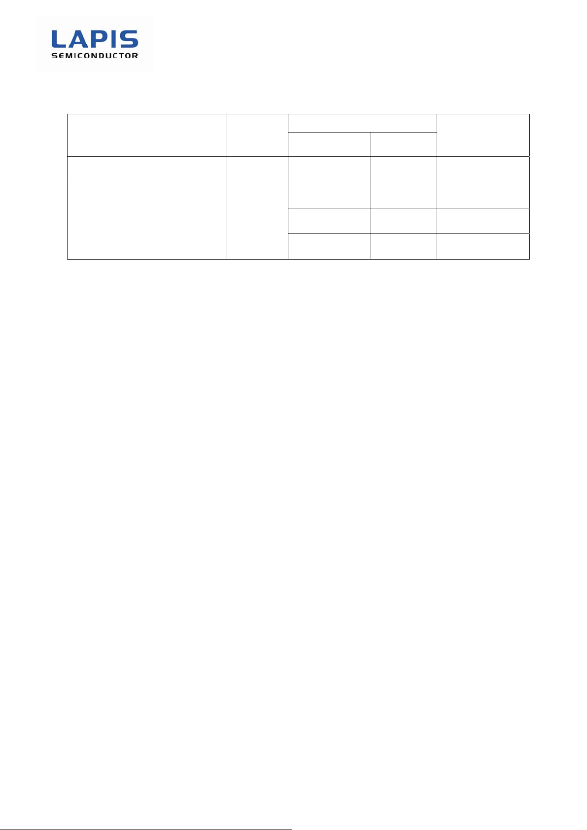
Revision History
Page
Document No. Issue Date
Previous Edition New Edition
FEXL7344_7406EVA_startguide-01 2013.7.25 – – First edition issued
Description
FEXL7344_7406EVA_startguide-02 2014.5.8 5 2
4
5 Added WCT setting
Added Control board
setting
Added Table of
jumper setting
FEXL7344_7406EVA_startguide-02 8
 Loading...