

Page 1

FEBL620Q150ARB-02
ML620Q150A Series Reference Board
ML620Q150A Series EVA Board
User’s Manual
Issue Date: Jan 14, 2016
Page 2
ML620Q150A Series Reference Board User’s Manual
FEBL620Q150ARB-02
NOTES
1) The information contained herein is subject to change without notice.
2) Although LAPIS Semiconductor is continuously working to improve product reliability and quality, semiconductors
can break down and malfunction due to various factors. Therefore, in order to prevent personal injury or fire arising
from failure, please take safety measures such as complying with the derating characteristics, implementing
redundant and fire prevention designs, and utilizing backups and fail-safe procedures. LAPIS Semiconductor shall
have no responsibility for any damages arising out of the use of our Products beyond the rating specified by LAPIS
Semiconductor.
3) Examples of application circuits, cir cuit constants and any other information contained h erein are provided only to
illustrate the standard usage and operations of the Products.The peripheral conditions must be taken into account
when designing circuits for mass production.
4) The technical information specified herein is intended only to show the typical functions of the Products and
examples of application circuits for the P roducts. No license, exp ressly or implied, is granted hereby under any
intellectual property rights or other rights of LAPIS Semiconductor or any third party with respect to the
information contained in this docu ment; therefore LAPIS Semiconductor shall have no responsibilit y whatsoever
for any dispute, concerning such rights owned by third par tie s, a rising out of the use of such technical information.
5) The Products are intended for use in general electronic equipment (i.e. AV/OA devices, communication, consumer
systems, gaming/entertainme nt sets) as well as the applications indica te d in this document.
6) The Products specified in this document are not designed to be radiation tolerant.
7) For use of our Products in applications requiring a high degree of reliability (as exemplified below), please contact
and consult with a LAPIS Semiconductor representative: transportatio n equipment (i.e. cars, ships, tr ains), pri mary
communication equipment, traffic lights, fire/crime prevention, safety equipment, medical systems, servers, solar
cells, and power transmission systems.
8) Do not use our Products in ap plications requiring e xtremely high reliabilit y, such as aerosp ace equipment, nuclear
power control systems, and submarine repeaters.
9) LAPIS Semico nd uctor shall h ave no resp onsib ilit y for an y da mages o r inj ury ar isi ng from non-compliance with the
recommended usage conditions and specifications contained herein.
10) LAPIS Semiconductor has used reasonable care to ensure the accuracy of the information contained in this
document. However, LAPIS Semiconductor does not warrant that such information is error-free and LAPIS
Semiconductor shall have no responsibility for any damages arising from any inaccuracy or misprint of such
information.
11) Please use the Products in accordance with any applicable environmental laws and regulations, such as t he RoHS
Directive. For more details, including RoHS compatibility, please contact a ROHM sales office. LAPIS
Semiconductor shall have no responsibility for any damages or losses resulting non-compliance with any applicable
laws or regulations.
12) When providing our Products and technologies contained in this document to other countries, you must abide by
the procedures and provisions stipulated in all applicable exp ort laws and regulations, incl uding without limitation
the US Export Administration Regulations and the F oreign Exchange and Fo reign Trade Act.
13) This document, in part or in whole, may not be reprinted or reproduced without prior consent of LAPIS
Semiconductor.
Copyright 2015-2016 LAPIS Semiconductor Co., Ltd.
2-4-8 Shinyokohama, Kouhoku-ku,
Yokohama 222-8575, Japan
http://www.lapis-semi.com/en/
FEBL620Q150ARB 1
Page 3
ML620Q150A Series Reference Board User’s Manual
RB-D620Q153TB48
ML620Q153A(64KB Flash) 48pinTQFP
RB-D620Q156TB52
ML620Q156A(64KB Flash) 52pinTQFP
works on ML620Q154A/155A/156A.
works on ML620Q157A/158A/159A.
ML620Q150A Series Reference Board.
FEBL620Q150ARB-02
Preface
This manual describes about the ML620Q150A Series Reference Board and ML620Q150A Series EVA Board.
There are three types of Reference Boards and an EVA Board can be used connecting to each reference board.
1. 48pinTQFP: ML620Q151A/152A/153A Reference Board
2. 52pinTQFP: ML620Q154A/155A/156A Reference Board
3. 64pinQFP: ML620Q157A/158A/159A Reference Board
Refer to following documents when necessary.
ML620Q150A Series User’s Manual
Describes about the microcontroller ML620Q150A Series.
uEASE U ser’s Manual
Describes about the On-chip debug tool uEASE.
ML620Q150A Series have nine products.
Table.1 List of the ML620Q150A Series microcontro ller
Part number ML620Q151A/152A/153A ML620Q154A/155A/156A ML620Q157A/158A/159A
Package 48pinTQFP 52pinTQFP 64pinQFP
Program FLASH size
ML620Q151A: 32KB
ML620Q152A: 48KB
ML620Q153A: 64KB
ML620Q154A:32KB
ML620Q155A:48KB
ML620Q156A:64KB
ML620Q157A:32KB
ML620Q158A:48KB
ML620Q159A:64KB
LAPIS support six types of reference boards and an evaluation board.
Table.2 List of the ML620Q150A Series Reference Board
Product name Mounted device/socket Note
RB-S620Q153TB48 48pinTQFP Socket
RB-S620Q156TB52 52pinTQFP Socket
RB-D620Q159GA64 ML620Q159A(64KB Flash) 64pinQFP One pcs of ML620Q159A-NNNTB is prepared
RB-S620Q159GA64 64pinQFP Socket
One pcs of ML620Q153A-NNNTB is prepared
into the socket, used for developing the software
works on ML620Q151A/152A/153A.
One pcs of ML620Q156A-NNNTB is prepared
into the socket, used for developing the software
into the socket, used for developing the software
EB-ML620Q150 -
Used as an evaluation board for the
FEBL620Q150ARB 2
Page 4
ML620Q150A Series Reference Board User’s Manual
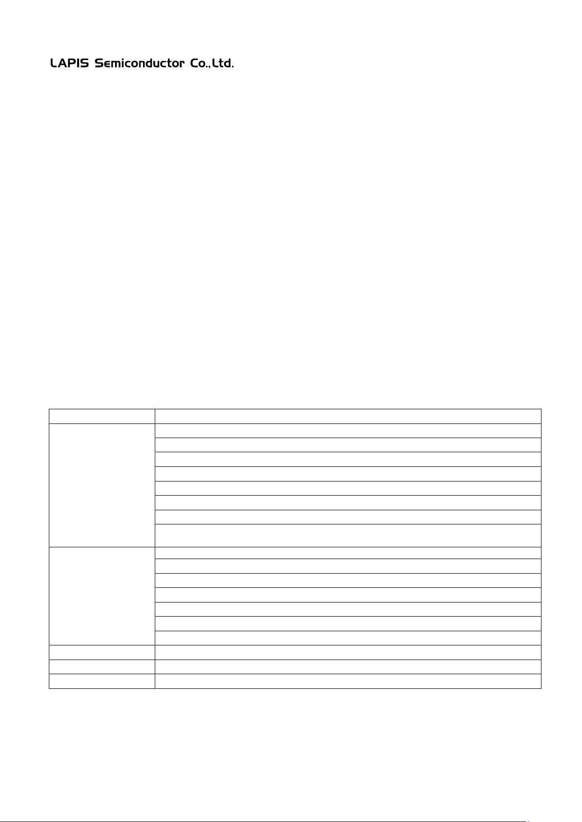
Mounted MCU
U1/U2 (The actual device / Socket) : ML620Q151A/2A/3A/4A/5A/6A/7A/8A/9A
PWR: Jumper for selecting the power supply input (3pin pin-header and shor t pin)
X1, X2: Crystal resonator (32.768kHz)
R1-R4: Resistors for lighting LEDs by P20 to P23
P20-P23: LEDs
C1-C5: Capacitors for Crystal resonator and power lines (for mounted device)
C6-C10: Capacitors for Crystal resonator and power lines (for device on the socket)
CN1-CN4: Connec to r s fo r EVA Board (20pin, 2.54mm pitch)
PP0-PP11: Pads for capacitors on the AIN pins
PP12-PP15: Pads for resistors connecting to LED
PP16-PP19: Pads for ferrite beads on the power line
PP20-PP21: Pads for capacitors on analog comparator input(noise filter purpose)
XP1-XP4: Pads for crystal resonators (for mounted device and device on the socket)
Other Through holes
VDD, VSS, VDDL1, VDDL2, AIN0-AIN11, CMP0P, CMP0M
Operating vo lta ge
+1.8V to +5.5V
Board size
90.00 mm x 120.00 mm
FEBL620Q150ARB-02
1. Overview
1.1 Features
The Reference Board is for learning how to us e the ML620Q150A Series of microcontrollers, on which adding
external user components if necessary. Using the Reference Board with LAPIS Semiconductor’s on-hip debug
emulator uEASE delivered with the software development environments, help user’s software development and
debugging a nd progra mming the Flash.
1.1.1 Board features
The board delivered with ML620Q150A series microcontroller or one of 48pin TQFP/ 52pin TQFP/ 64pin TQFP
socket.
Available functions of programming the Flash ROM and on-chip debugging the software (P14/TEST0 and TEST1_N
are used for the communication).
Through-holes for connecting the pins of microcontroller to external pheripheral boards.
The power supply is selectable, supplied from the on-chip debug emulator uEASE or an user pheripheral board.
Pads for mounting components, useful for evaluating the microcontroller.
EVA Board is available to be connected to the Reference Board, which has a RS232C connector and external
component s , useful when evaluating ISP function or A/D converter.
1.1.2 Hardware specifications
See the schematic on page 22 to 26 for more detail about connection of the mounted component s .
1. Reference Board
Table.3 ML620Q150A Serie s Reference Board Components Overview
VREF: VREF pin input (3pin pin-header and shor t pin)
MODE: Jumper for selecting P14/TEST0 pin (3pin pin-header and short pin)
Other
Mounted components
CNUE: Connecto r for On-chip debug emulator uEASE (14pin connector)
Pads (or/and)
Through hole s for
mounting components
XR1-XR2: Pads for series resistance of crystal resonator
FEBL620Q150ARB 3
Page 5
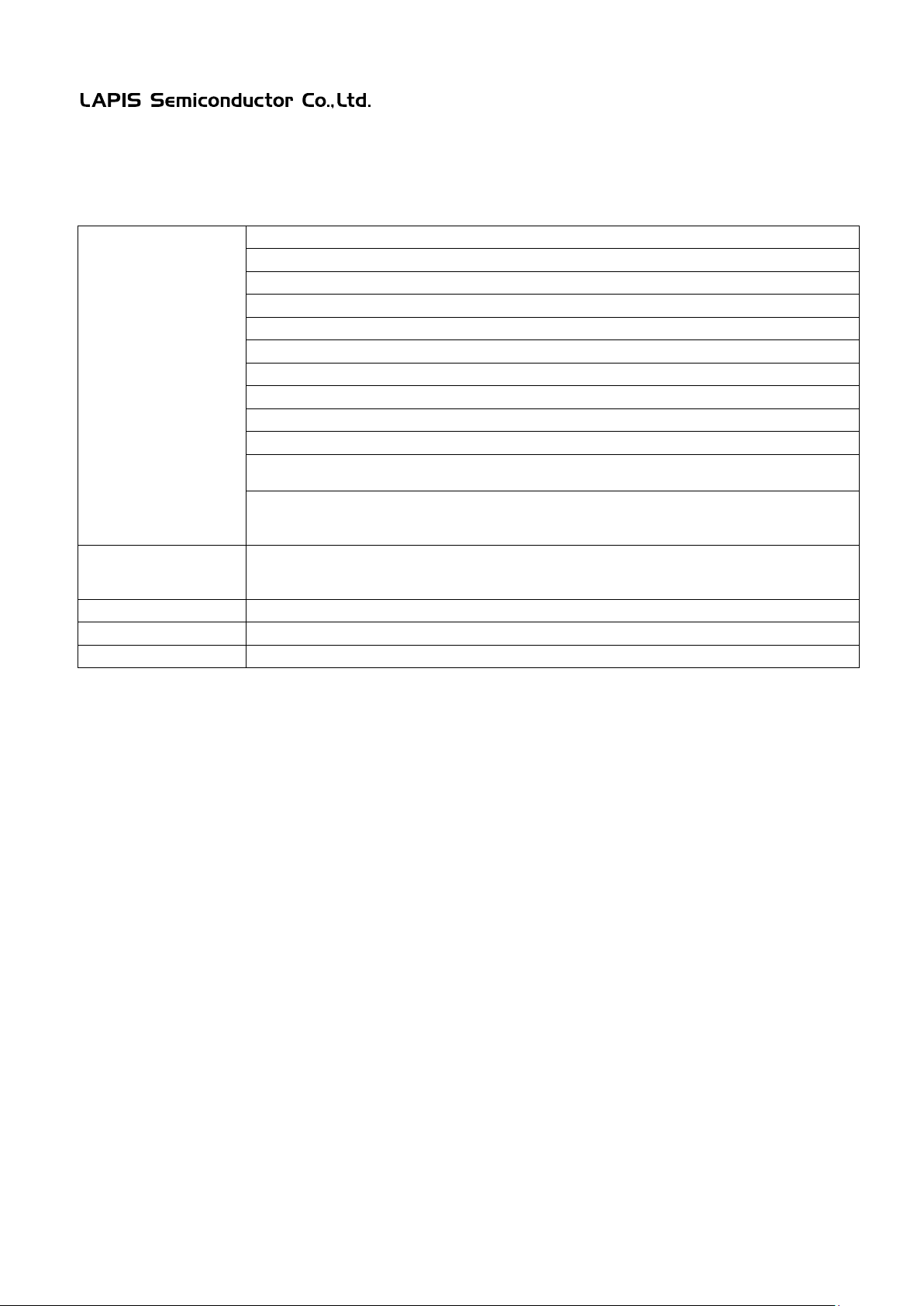
VDD, VSS: Check pi ns
RESET_N, SW0-SW5: PUSH switches (7pcs)
RES_ENA: Jumper for selecting the RESET pin (3pin pin header and short pin)
SEL0-SEL11: Jumper for selecting AIN or P3 (3pin pin header and short pin)
D1-D24: Diodes for AIN input pin.
CN5: RS232C connector
TXD, RXD: TXD/RXD connec tion selector for RS232C Interface IC
R1-R12: AINn pin series resistor ( 12pcs)
R13: RS232C transmit pin resistor (1pc s)
C1-C5: Capacitors for power circuits(5pcs)
C11-C17: Capacitors for PUSH switches(7pcs)
Pads (or/and)
mounting components
Operating vo lta ge
+1.8V to +5.5V
Board size
140.00mm x 180.00 mm
2. EVA Board
Mounted components
ML620Q150A Series Reference Board User’s Manual
FEBL620Q150ARB-02
Table.4 ML620Q150A Series EVA Board Components Overview
CN1-CN4: Connector for ML620Q150A Series Reference Board
VREF: Jumper for selecting the VREF pin (3pin pin header and short pin)
U1: RS232C Interface IC
C6-C10: Capacitors for RS232C interface IC(5pcs)
Through ho l es for
PP1: Pad for a capacitor placed between VREF and VSS
Other Through holes AIN0-AIN11, P30-P35, P42-P47: Check pins
FEBL620Q150ARB 4
Page 6
ML620Q150A Series Reference Board User’s Manual
P20-P22
CN1
VREF
AIN0-AIN2
PWR
CNUE
CN2
CN4
U1
U2
CN3
MODE
X2
X1
1pin
FEBL620Q150ARB-02
1.2 Reference Board Outline Drawing
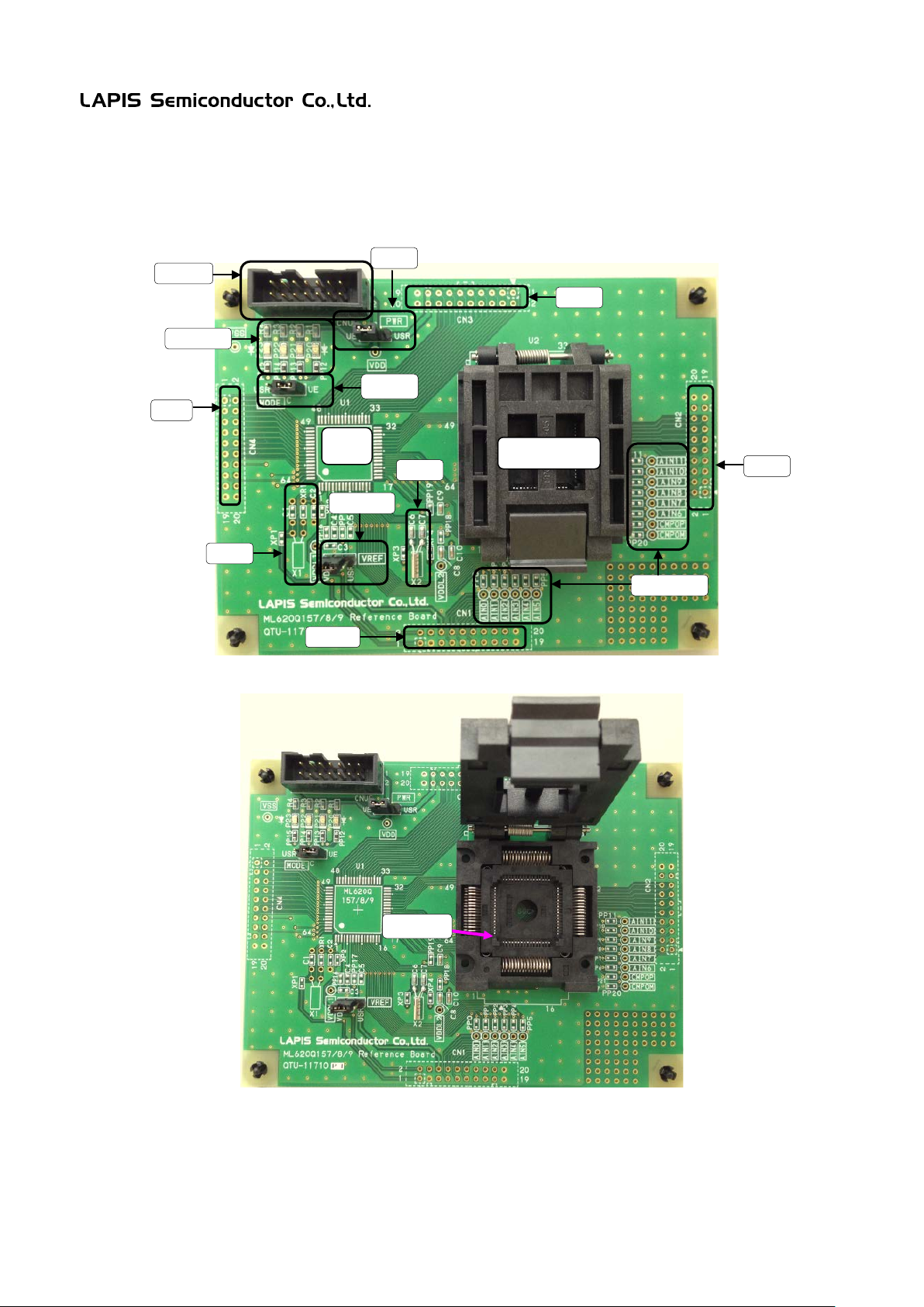
The Figure.1 and Figure.2 show the ML620Q150A Series Reference Board, on which as an example the 64pin QFP
socket for ML620Q157A/8A/9A is mounted.
Fig.1 ML620Q150A Series Reference Board Outline Drawing
▲
Fig.2 ML620Q150A Series Reference Board Socket 1pin direction
【Note】
Place the microcontroller Reference Board when turning off the power supply. Place the microcontroller in the
right direction.
FEBL620Q150ARB 5
Page 7
FEBL620Q150ARB-02
CN5
SEL0-5
CN2
SEL6-11
SW0-5
RES_ENA
VREF
CN1
RESET_N
CN4
CN3
VSS
VDD
1.3 EVA Board Outline Drawing
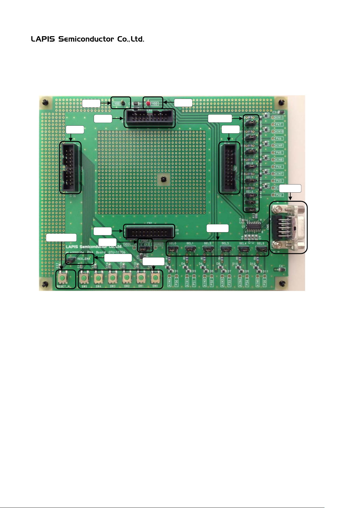
The Figure.3 show the ML620Q150A Series EVA Board.
ML620Q150A Series Reference Board User’s Manual
Fig.3 ML620Q150A Series EVA Board Outline Drawing
FEBL620Q150ARB 6
Page 8
ML620Q150A Series Reference Board User’s Manual
1 2 3 4 5 6 7 8 9
10
11
12
13
14
UVDD
PWR
UVDD
(CN3)
VTREF
VPP
SCLK
SDATA
VDDL
NC
NC
3.3VOUT
VSS
UVREF
(CN1)
VREF
VREF
Connector for uEASE (CNUE)
2.2uF
1uF
VDD
TEST1_N
TEST1_N
P14/TEST0
VDDL
2.2uF
P14/TEST0
(CN4)
PP16
P14/TEST0
(CN4)
VDDL1
PP17
USR
uE
USR
VDD
MODE
USR
uE
ML610Q150A series
Device or IC Socket
1608 size pad
0.8mm
FEBL620Q150ARB-02
2. Function of Reference Board
2.1 Power Circuit
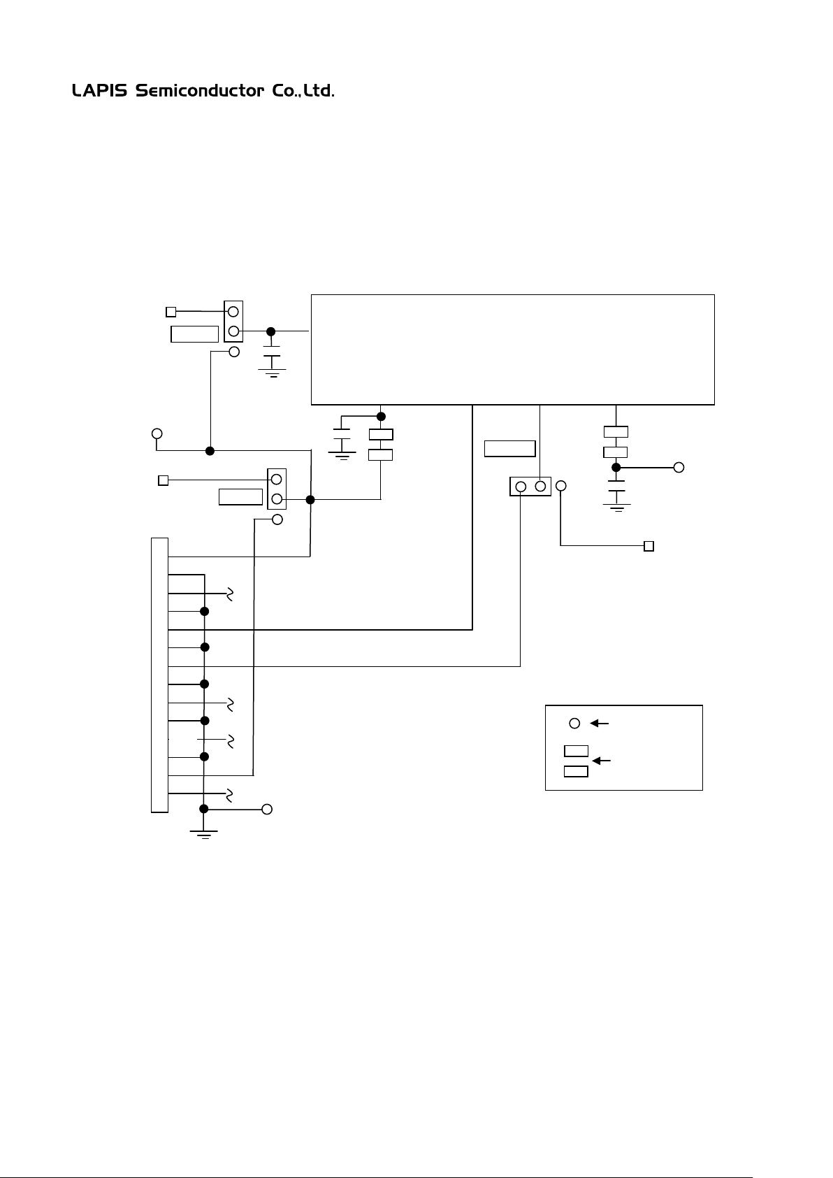
Power supply for VDD is selectable by PWR jumper (uEASE/USR).
Power supply for VREF is selectable by VREF jumper (VDD/USR)
Fig.4 Power Circuit
[Note]
When selecting “USR” on the PWR jumper and connecting uEASE, connect the uEASE at first and power up the
user application system the second. As well, power off the user application system at first and power off the uEASE
the second.
When selecting “VREFF” on the VREF jumper and co nencting uEASE, connect the uEASE at first and power up the
user application system the second. As well, power off the user application system at first and power off the uEASE
the second.
When selecting “USR” on the MODE jumper, uEASE is not available to use and instead P14/TEST0 pin on the
microcontroller is available to use.
FEBL620Q150ARB 7
Page 9
ML620Q150A Series Reference Board User’s Manual
X1
ML610Q150A series
Device(U1)
P13/XT1
P12/XT0
ML610Q150A series
IC Socket(U2)
P13/XT1
P12/XT0
C1
C2
X2
C6
C7
CN1
P12
P13
XP1
XP2
XP3
XP4
1608 size pad
0.8mm
XR1
FEBL620Q150ARB-02
2.2 Low-speed Oscillation Circuit
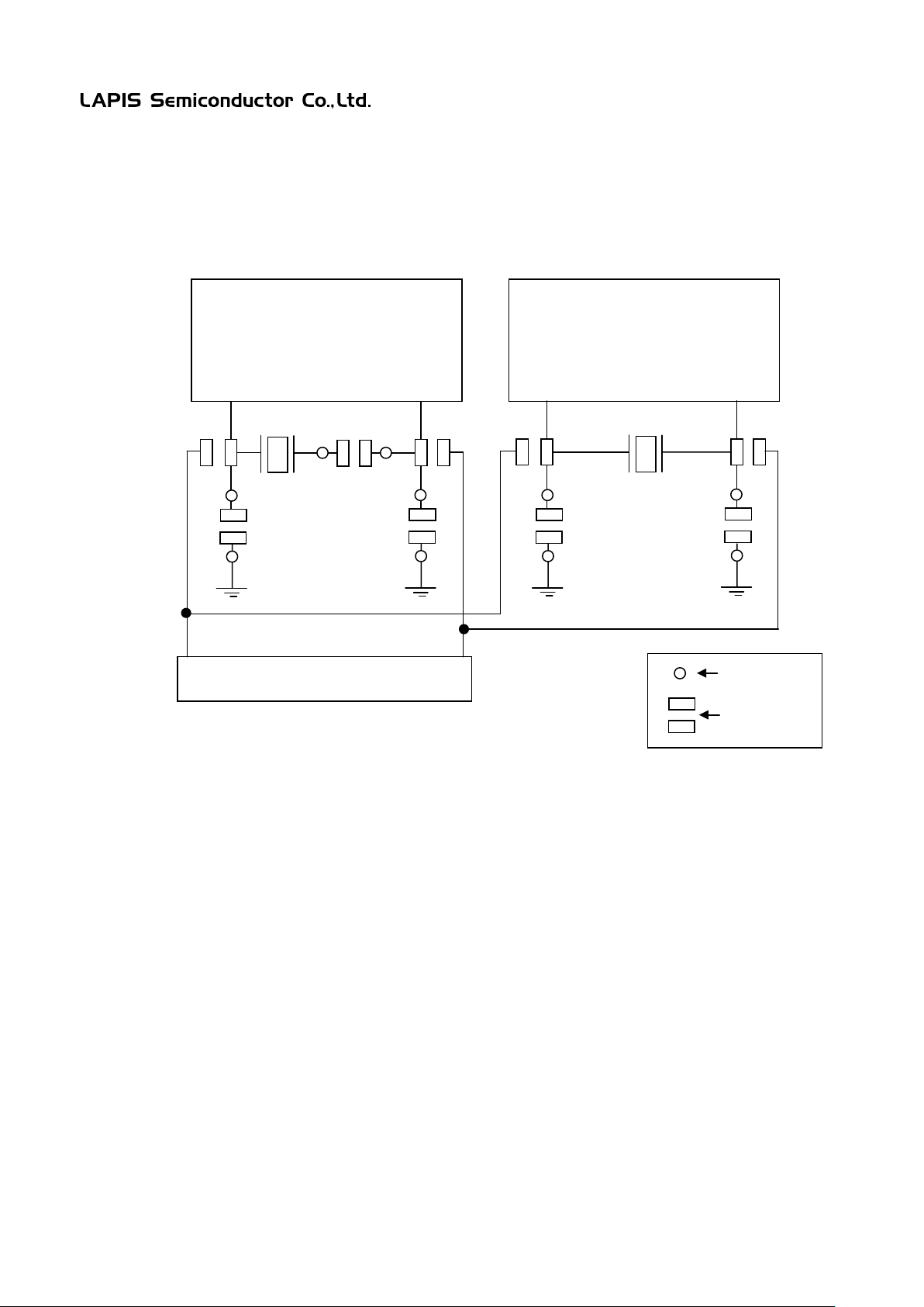
The low-speed oscillation circuit is available for each device mounted type(U1) and soket type (U2).
The 1608 size of pads are prepared so that the PCB wiring capacitance does not affect to the oscillation.
12pF
Fig.5 Low-speed Oscillation Circuit
FEBL620Q150ARB 8
Page 10
ML620Q150A Series Reference Board User’s Manual
P30/AIN0
AIN0
AIN1
AIN2
AIN3
AIN4
AIN5
AIN6
AIN7
AIN8
AIN9
AIN10
AIN11
ML610Q150A series
IC Socket
P31/AIN1
P32/AIN2
P33/AIN3
P34/AIN4
P35/AIN5
P36/AIN6
P37/AIN7
P34/AIN8
P35/AIN9
P36/AIN10
P37/AIN11
1608 size pad
0.8mm
FEBL620Q150ARB-02
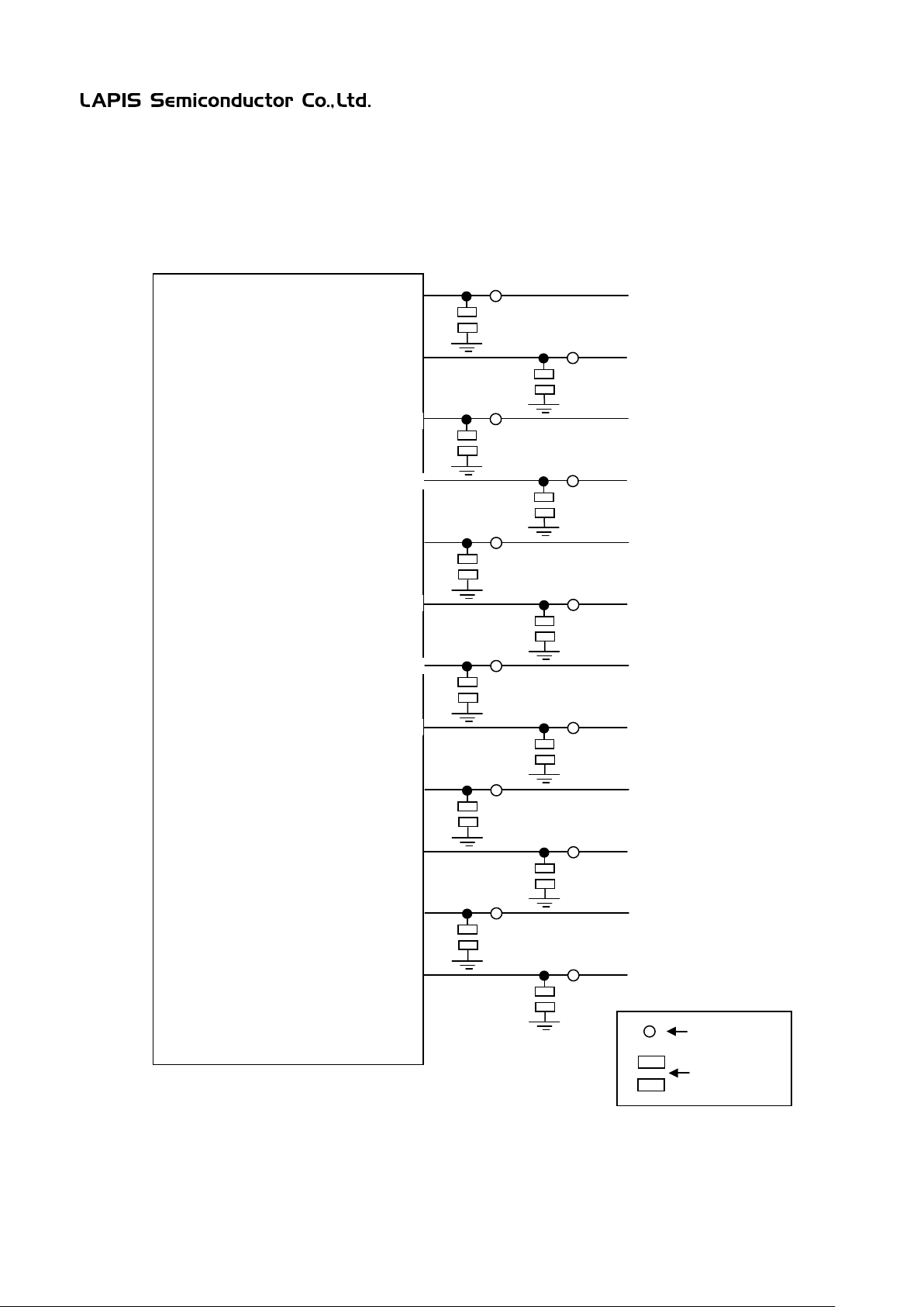
2.3 AIN inputs for evaluating the A/D Converter
Through-holes(AIN0-AIN11) are a vailable to input voltages direclty to the pins of microtontroller.
The 1608 size of pads can be used for external components such as denoising capactors.
Device or
Fig.6 AIN inputs for evaluating the A/D converter
FEBL620Q150ARB 9
Page 11
ML620Q150A Series Reference Board User’s Manual
ML610Q150A series
IC Socket
P40/CMP0M
CMP0M
CMP0P
P41/CMP0P
P40
P41
CN2
1608 size pad
0.8mm
FEBL620Q150ARB-02
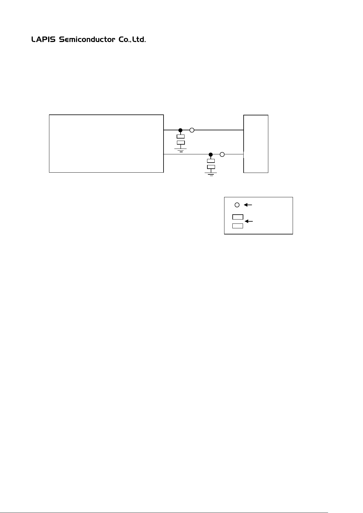
2.4 Analog Comparator Input
Through-holes( COM0M, CMP0P) are available to input voltages direclty to the pins of mi c rotontroller.
The 1608 size pads can be used for mounting denoising capactors.
Device or
Fig.7 Analog Comparator Input
FEBL620Q150ARB 10
Page 12
ML620Q150A Series Reference Board User’s Manual
1 2 3 4 5 6 7
8
9
10
11
12
13
14
UVDD
PWR
UVDD
(CN3)
VTREF
VPP
SCLK
SDATA
VDDL
NC
NC
3.3VOUT
VSS
UVREF
(CN1)
VREF
VREF
Connector for uEASE (CNUE)
2.2uF
1uF
VDD
TEST1_N
TEST1_N
P14/TEST0
VDDL
2.2uF
P14/TEST0
(CN4)
PP16
P14/TEST0
(CN4)
VDDL1
PP17
USR
uE
USR
VDD
MODE
USR
uE
ML610Q150A series
Device or IC Socket
1608 size pad
0.8mm
FEBL620Q150ARB-02
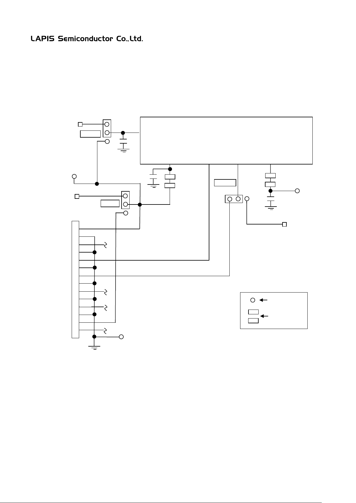
2.5 uEASE Interface
Selecting a jumper pin on the MODE jumper, one of the on-chip debug emulator uEASE or a genral port P14 is
available to use.
Fig.8 uEASE Interface
[Note]
When selecting “USR” on the MODE jumper, uEASE is not available to use and instead P14/TEST0 pin on the
microcontroller is available to use.
FEBL620Q150ARB 11
Page 13
ML620Q150A Series Reference Board User’s Manual
Top View
Through-holes for
Pads for mounting
Top View
Remove when not
using the LEDs.
FEBL620Q150ARB-02
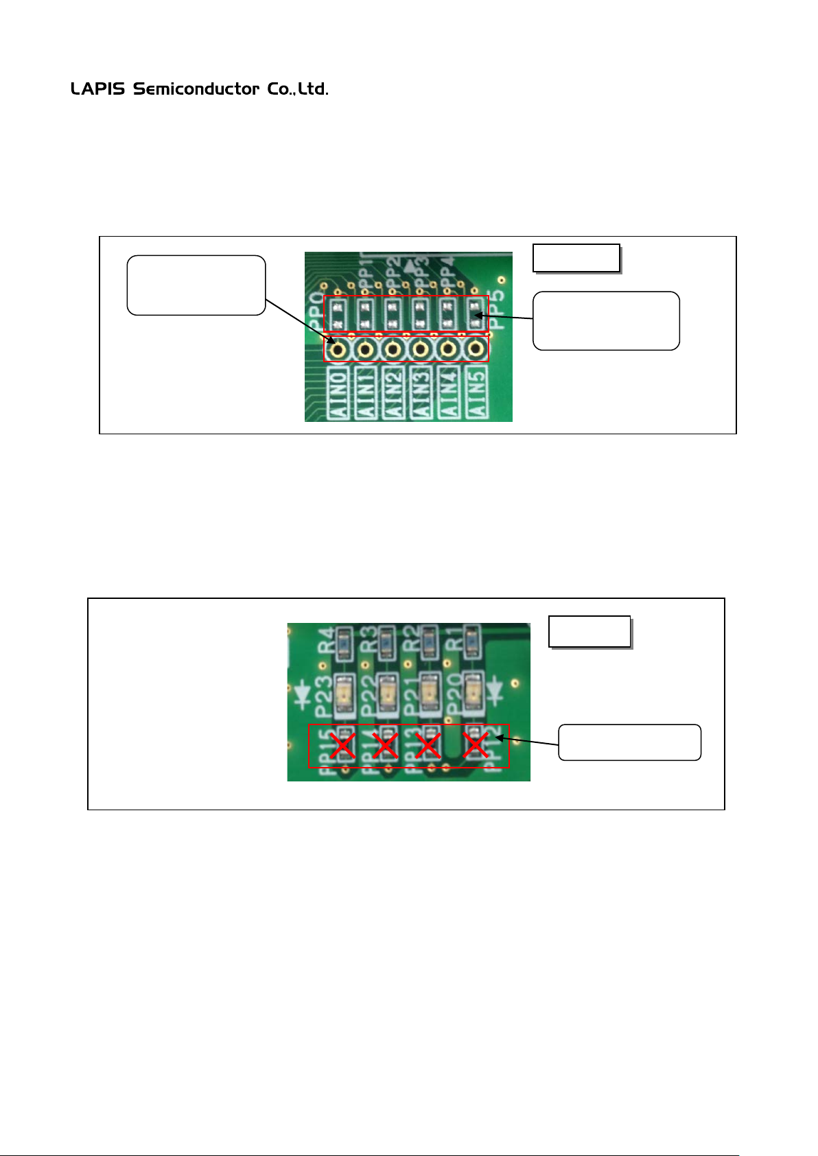
2.6 When using the A/D Converter
The throug h-holes AIN0 to AIN11 that are close to the device are prepared to evaluate the A/D converter. Place
denoise-purpose capctiors onto the pads PP0 to PP11 if necessary.
inputting signals to
AINn pins.
denoise-purpose
capacitors.
Fig.9 Through-holes and Pads used for A/D converter function
2.7 When Not using the LED
P20-P22 of the microcontroller are ports that can directly drive a LED. The Ports are connected to the LEDs through
zero-ohm chip resistors. Remove the resist ors when not using the LEDs.
Fig.10 Zero-ohm resistors for LEDs
FEBL620Q150ARB 12
Page 14
ML620Q150A Series Reference Board User’s Manual
T1OUT
T2OUT
R1IN
R2IN
T1IN
T2IN
DCD
RXD
TXD
DTR
VSS
DSR
RTS
CTS
RI
1
2
3 9 4 5 6 7 8
14 7 13
8
C2+
C2-
V+
V-
2 6 0.22uF
0.22uF
0.22uF
4
5
C1+
C1-
1 3 0.22uF
VCC
VSS
16
15
VDD
P42/AIN6/RXD0
9pin D-SUB
Connector for
ILC3232
0.1uF
11
10
12
9
P43/AIN7/TXD0
FEBL620Q150ARB-02
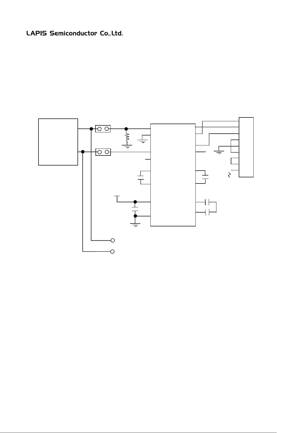
3. Function of EVA Board
3.1 RS232C Communication Circuit
P43/AIN7/TXD0 and P42/AIN6/RXD0 are disconnectable from the RS232C circuit by using the TXD jumper and
RXD jumper.
Fig.11 RS232C Communication Circuit
Connector
FEBL620Q150ARB 13
Page 15
ML620Q150A Series Reference Board User’s Manual
Connector for
FEBL620Q150ARB-02
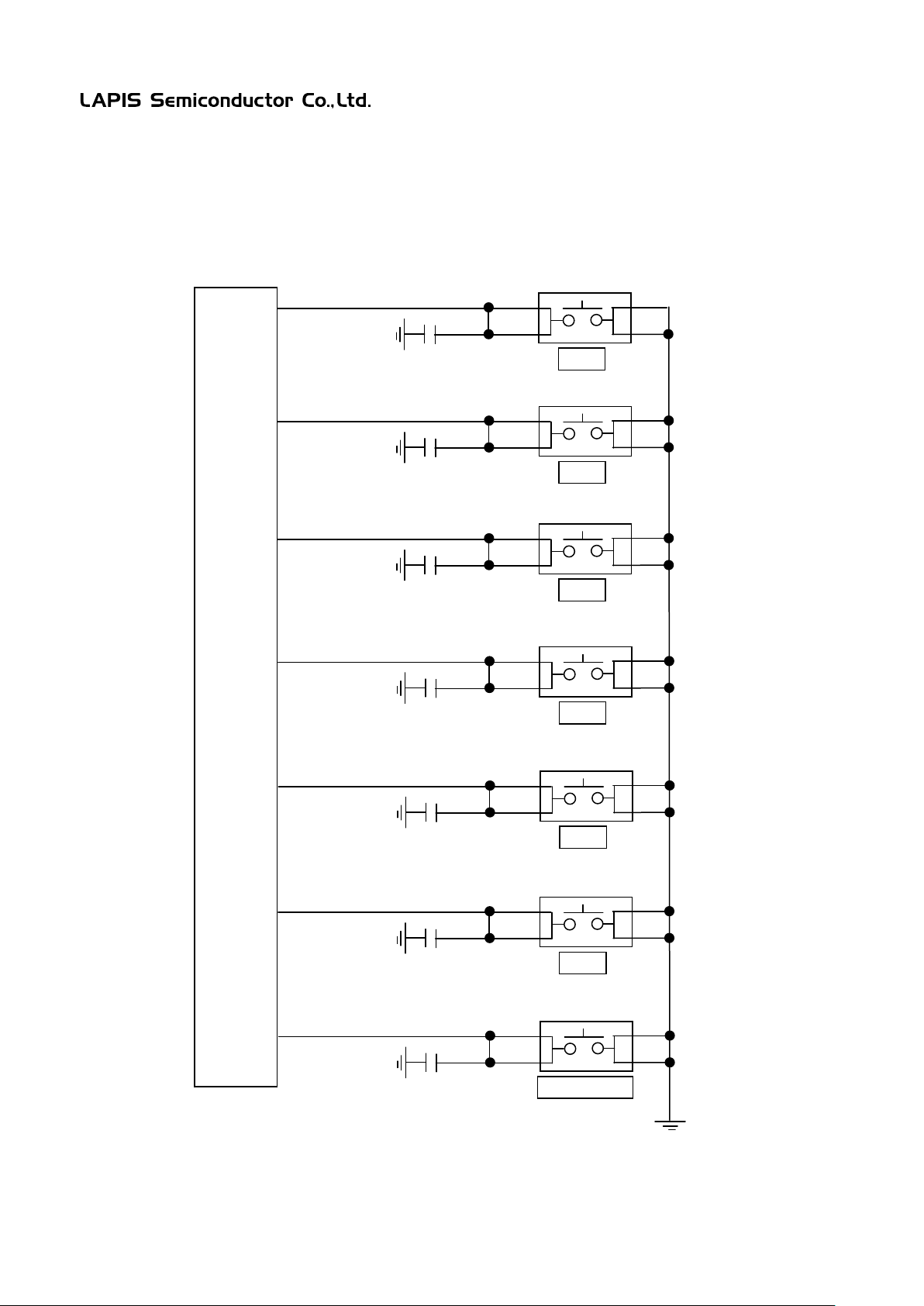
3.2 Input Switch
Five push swiches are available connected to Port 0(P05-P00) and RESET_N pin.
The swich for the RESET_N is disconnectable by using the RESET_N jumper.
Fig.12 Input Switches
FEBL620Q150ARB 14
Page 16
ML620Q150A Series Reference Board User’s Manual
Connector for
P30/AIN0
P31/AIN1
P32/AIN2
SEL1
C
2
2
1
VDD
AIN1
P31
AIN2
P32
AIN11
P47
P47/AIN11
.
.
VREF
VREF
C 2 2 1 VDD
EXVREF
1608 size pad
0.8mm
PP1
.
.
SEL0
C
2
2
1
VDD
AIN0
P30
D1
D2
R1
D3
D4
R2
FEBL620Q150ARB-02
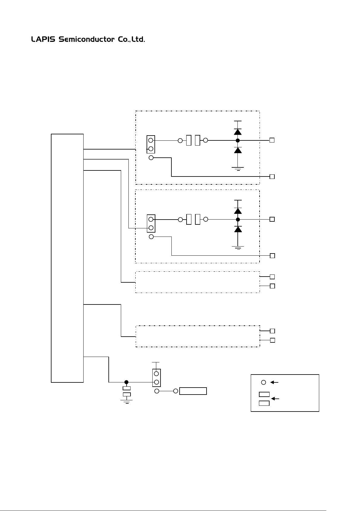
3.3 AIN Input for A/D Converter
The input circuits are selectable by using the SELn jumpers. One input line has diodes and a resistor for the
evaluation.
VDD or an external voltage supp lie d to the VREF pin is selectable by the VREF jumper.
.
.
.
.
.
.
.
.
Fig.13 AIN inputs for A/D Converter
FEBL620Q150ARB 15
Page 17
ML620Q150A Series Reference Board User’s Manual
Q157A/8A/9A
64pin device
Q154A/5A/6A
52pin device
Q151A/2A/3A
48pin device
Q157A/8A/9A
64pin device
Q154A/5A/6A
52pin device
Q151A/2A/3A
48pin device
1
P12
P12
P12 1 P40
P40
P40
2
P13
P13
P13 2 P41
P41
P41
3
VSS
VSS
VSS
3
P42
P42
P42
4
−
−
−
4
P43
P43
P43
5
−
−
−
5
P44
P44
P44
6
VREF
VREF
VREF
6
P45
P45
P45 7 P30
P30
P30 7 P46
P46
P46 8 P31
P31
P31 8 P47
P47
P47
9
P32
P32
P32 9 P50
−
−
10
P33
P33
P33
10
P51
−
−
11
P34
P34
P34
11
P52
−
−
12
P35
P35
P35
12
P53
P53
−
13
P36
P36 − 13
P54
P54
P54
14
P37
−
−
14
P55
P55
P55
15
P70
−
−
15
P56
P56
P56
16
P71
−
−
16
P57
P57
P57
17
− − −
17
− − −
18
− − −
18
− − −
19
VSS
VSS
VSS
19
VSS
VSS
VSS
20
VSS
VSS
VSS
20
VSS
VSS
VSS
CN3
Q157A/8A/9A
64pin device
Q154A/5A/6A
52pin device
Q151A/2A/3A
48pin device
CN4
Q157A/8A/9A
64pin device
Q154A/5A/6A
52pin device
Q151A/2A/3A
48pin device
1
P60
P60
P60 1 P00
P00
P00
2
P61
P61
P61 2 P01
P01
P01
3
P62
P62
P62 3 P02
P02
P02 4 P63
P63
P63 4 P03
P03
P03
5
P64
P64 − 5
P04
P04
P04 6 P65
−
−
6
P05
P05
−
7
P66
−
−
7
P20
P20
P20 8 P67
−
−
8
P21
P21
P21
9
P80
P80
P80 9 P22
P22
P22
10
P81
P81
P81
10
P23
P23
P23
11
P82
P82
P82
11
P72
−
−
12
P83
P83
P83
12
P73
−
−
13
P84
P84
P84
13
P74
−
−
14
P85
P85
P85
14
P14/TEST0
P14/TEST0
P14/TEST0
15
P86
P86
P86
15
RESET_N
RESET_N
RESET_N
16
P87
P87
P87
16
− − −
17
VDD
VDD
VDD
17
− − −
18
VDD
VDD
VDD
18
− − −
19
VSS
VSS
VSS
19
VSS
VSS
VSS
20
VSS
VSS
VSS
20
VSS
VSS
VSS
FEBL620Q150ARB-02
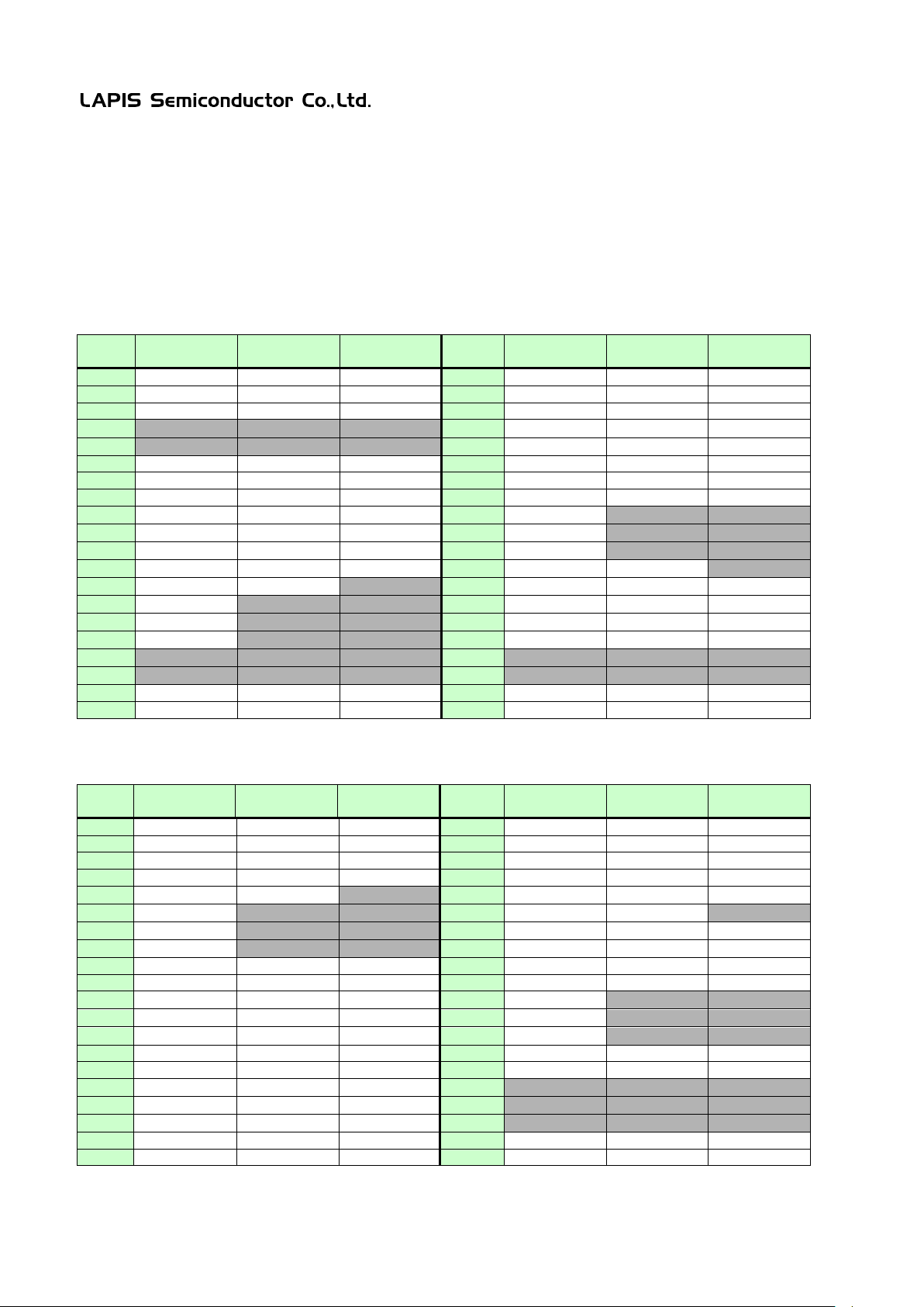
4. User Interface
4.1 ML620Q150A Series Reference Boar d User Interface
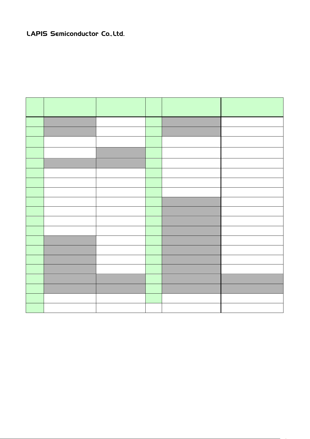
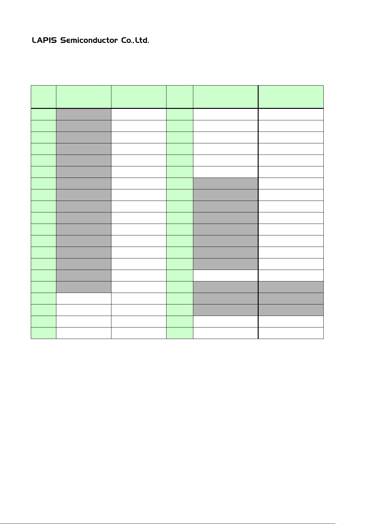
Table 5. and Table 6. show the pin list of the ML620Q150A series reference board user interface connector CN1, CN2,
CN3 and CN4.
Table 5. ML620Q150A Series Reference Board User Interface Connecter CN1/CN2 Pin List
CN1
CN2
Table 6. ML620Q150A Series Reference Board User Interface Connecter CN3/CN4 Pin List
FEBL620Q150ARB 16
Page 18
ML620Q150A Series Reference Board User’s Manual
Reference Board
Reference Board
1 − P12
1 − P40
2 − P13
2 − P41
P42/AIN6 Input circuit
or RXD0
−
P43/AIN7 Input circuit
or TXD0
5
−
−
5
P44/AIN8 Input circuit
P44/AIN8
6
VREF
VREF
6
P45/AIN9 Input circuit
P45/AIN9
7
P30/AIN0 Input circuit
P30/AIN0
7
P46/AIN10 Input circuit
P46/AIN10
8
P31/AIN1 Input circuit
P31/AIN1
8
P47/AIN11 In put cir cuit
P47/AIN11
9
P32/AIN2 Input circuit
P32/AIN2
9 − P50
10
P33/AIN3 Input circuit
P33/AIN3
10 − P51
11
P34/AIN4 Input circuit
P34/AIN4
11 − P52
12
P35/AIN5 Input circuit
P35/AIN5
12 − P53
13 − P36
13 − P54
14 − P37
14 − P55
15 − P70
15 − P56
16 − P71
16 − P57
17
−
−
17
−
−
18
−
−
18
−
−
19
VSS
VSS
19
VSS
VSS
20
VSS
VSS
20
VSS
VSS
FEBL620Q150ARB-02
4.2 ML620Q150A Series EVA Board User Interface
Table 7. and Table 8. show the pin list of the ML620Q150A series eva board user interface connector CN1, CN2, CN3
and CN4 (Listed all pins of the 64pin devices).
Table 7. ML620Q150A Series EVA Board User Interface Connecter CN1/CN2 Pin List
CN1 EVA Board 64pin device
3 VSS VSS 3
4 VDDL(TH)
CN2 EVA Board 64pin device
P42/AIN6/RXD0
4
P43/AIN7/TXD0
FEBL620Q150ARB 17
Page 19
ML620Q150A Series Reference Board User’s Manual
Reference Board
Reference Board
1
-
P60 1 Push SW
P00
2
-
P61 2 Push SW
P01
3
-
P62 3 Push SW
P02
4
-
P63 4 Push SW
P03
5
-
P64 5 Push SW
P04
6
-
P65 6 Push SW
P05
7
-
P66
7
-
P20
8
-
P67
8
-
P21
9
-
P80
9
-
P22
10
-
P81
10
-
P23
11
-
P82
11
-
P72
12
-
P83
12
-
P73
13
-
P84
13
-
P74
14
-
P85
14
-
P14/TEST0
15
-
P86
15
Push SW
RESET_N
16
-
P87
16
-
-
17
VDD
VDD
17
-
-
18
VDD
VDD
18
-
-
19
VSS
VSS
19
VSS
VSS
20
VSS
VSS
20
VSS
VSS
FEBL620Q150ARB-02
Table 8. ML620Q150A Series EVA Board User Interface Connecter CN3/CN4 Pin List
CN3 EVA Board 64pin device
CN4 EVA Board 64pin device
FEBL620Q150ARB 18
Page 20

ML620Q150A Series Reference Board User’s Manual
FEBL620Q150ARB-02
5. Precaution for use
(1) Since the content spe cified her ein is subject to change for improvement without notice, confirm the content is the
latest when using the board.
(2) See another documents ML620Q150A series user’s man ual and uEASE user’s manual when using the board.
(3) The Reference Board may have an engineering sample of the ML620Q150A series. Confirm the final electrical
characteristics by using the mass production parts on your mass production boards.
(4) LAPIS support replacing the board for an initial failure soon after the shipment, can not support reparing the board.
(5) The boards have signal patterns on the underside, it might work in abnormal if using on conductive materials. Use it
on insulating materials or having any preventable parts.
FEBL620Q150ARB 19
Page 21
ML620Q150A Series Reference Board User’s Manual
FEBL620Q150ARB-02
6. PCB specification and schematic
6.1 Reference Board PCB specification
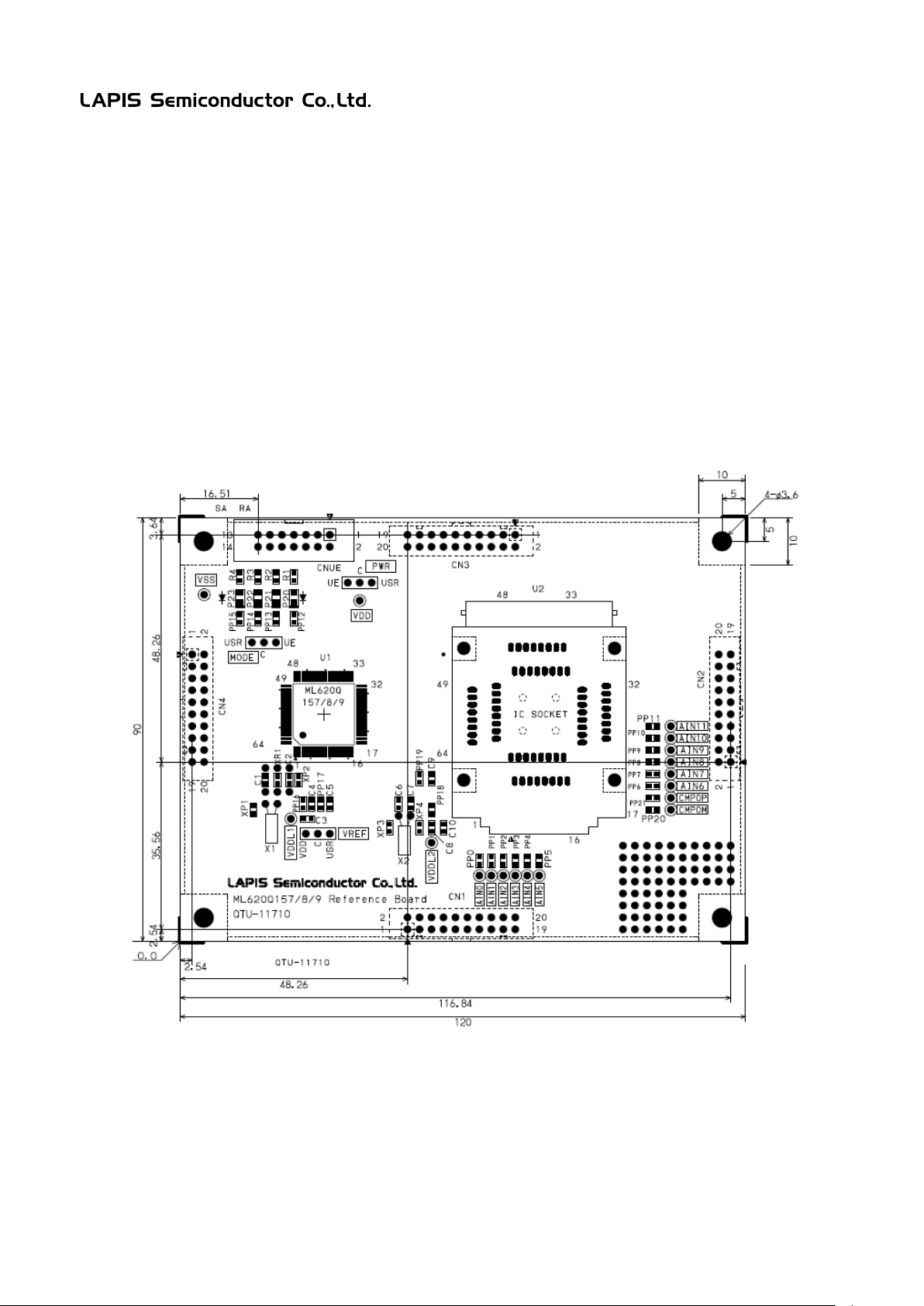
Figure 14. shows the ML620Q150A Series Reference Board PCB dimensional outline drawing and layout of
components.
PCB part number:
ML620Q151A/2A/3A Reference Board (QTU-11708)
ML620Q154A/5A/6A Reference Board (QTU-11709)
ML620Q157A/8A/9A Reference Board (QTU-11710)
Dimension:
90mm x 120mm
Fig.14 Reference Board PCB dimensional outline drawing and layout of components (Top view)
FEBL620Q150ARB 20
Page 22
ML620Q150A Series Reference Board User’s Manual
FEBL620Q150ARB-02
6.2 EVA Board PCB Specification
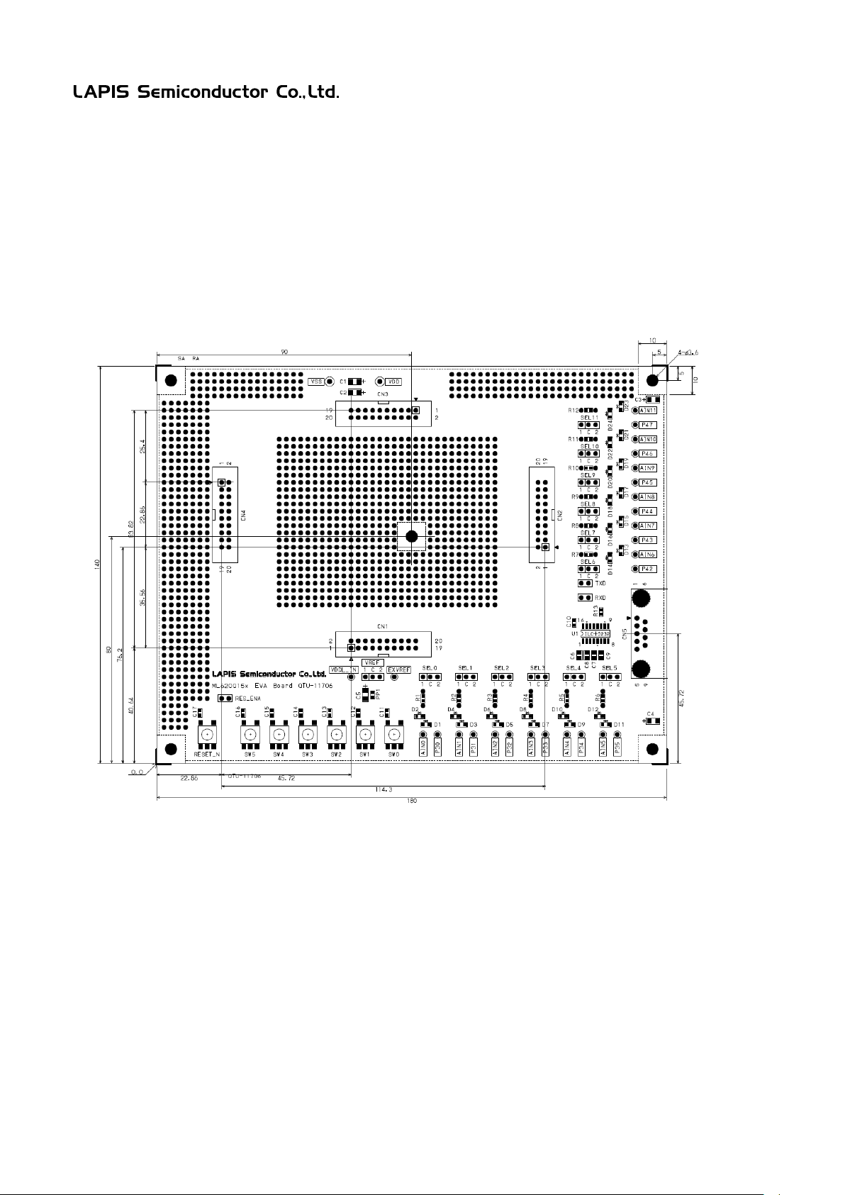
Figure 14. shows the ML620Q150A Series EVA Board PCB dimensional outline drawing and l ayout of co mponents.
PCB part number:
ML620Q15xA EVA Board (QTU-11 7 05)
Dimension:
140mm x 180mm
Fig.15 EVA Board PCB dimensional outline drawing and layout of components (Top view)
FEBL620Q150ARB 21
Page 23

ML620Q150A Series Reference Board User’s Manual
FEBL620Q150ARB-02
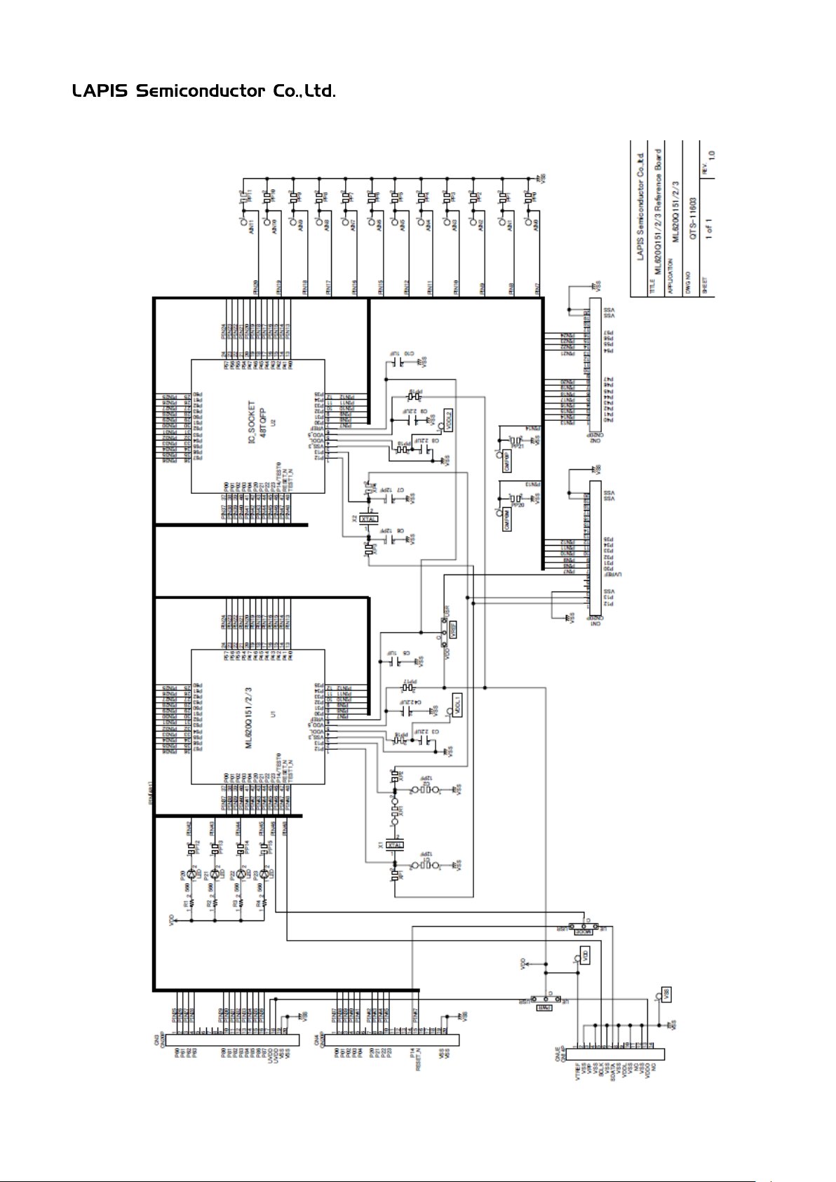
6.3 Reference Board Schematic
The next page shows the schematic of ML620Q150A Series Reference Board
FEBL620Q150ARB 22
Page 24
ML620Q150A Series Reference Board User’s Manual
FEBL620Q150ARB-02
FEBL620Q150ARB 23
Page 25

ML620Q150A Series Reference Board User’s Manual
FEBL620Q150ARB-02
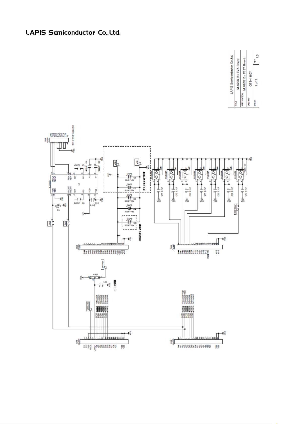
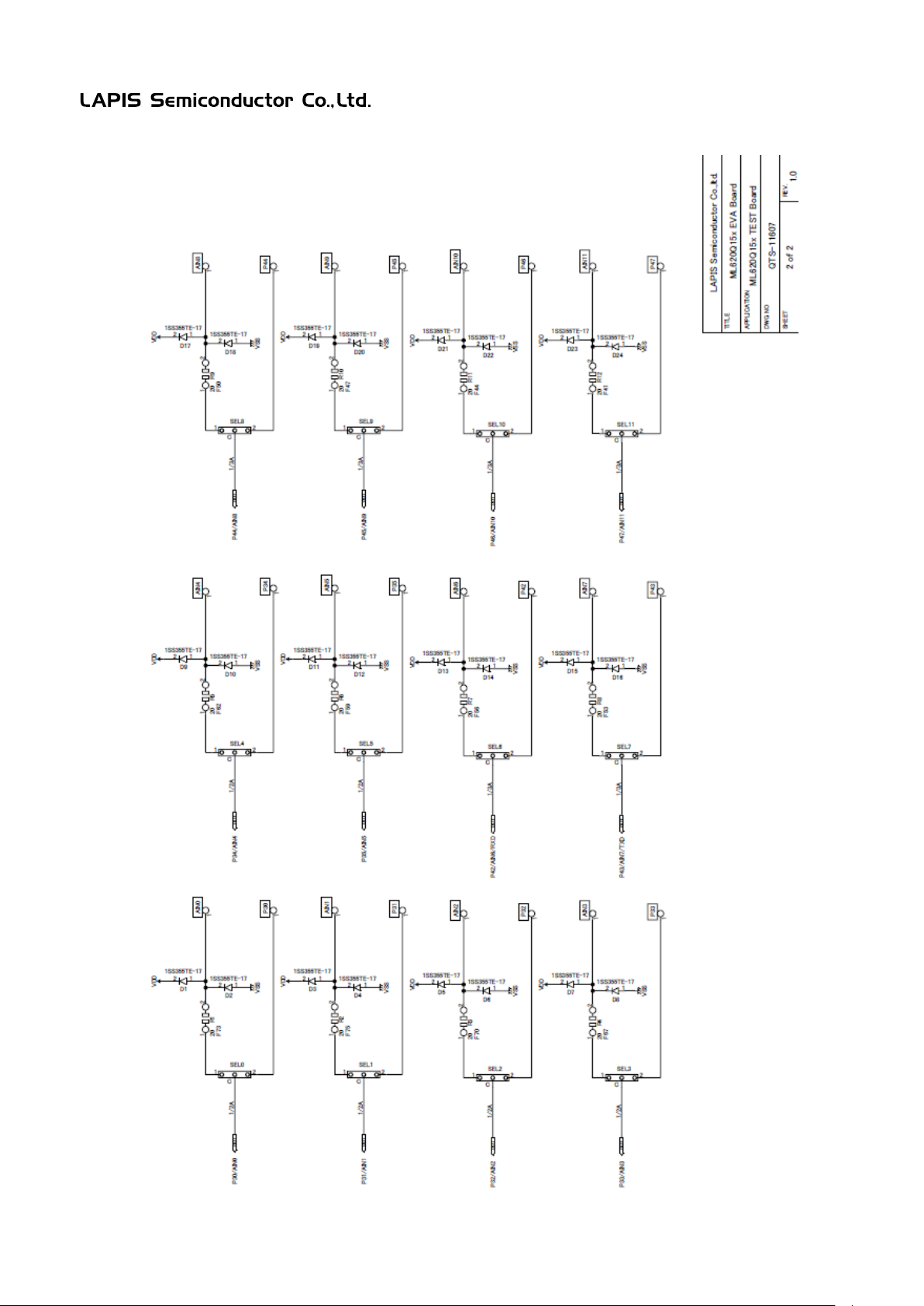
6.4 EVA Board Schematic
The next page shows the schematic of ML620Q150A Series EVA Board
FEBL620Q150ARB 24
Page 26
ML620Q150A Series Reference Board User’s Manual
FEBL620Q150ARB-02
FEBL620Q150ARB 25
Page 27
ML620Q150A Series Reference Board User’s Manual
FEBL620Q150ARB-02
FEBL620Q150ARB 26
Page 28
Page
Edition
Edition
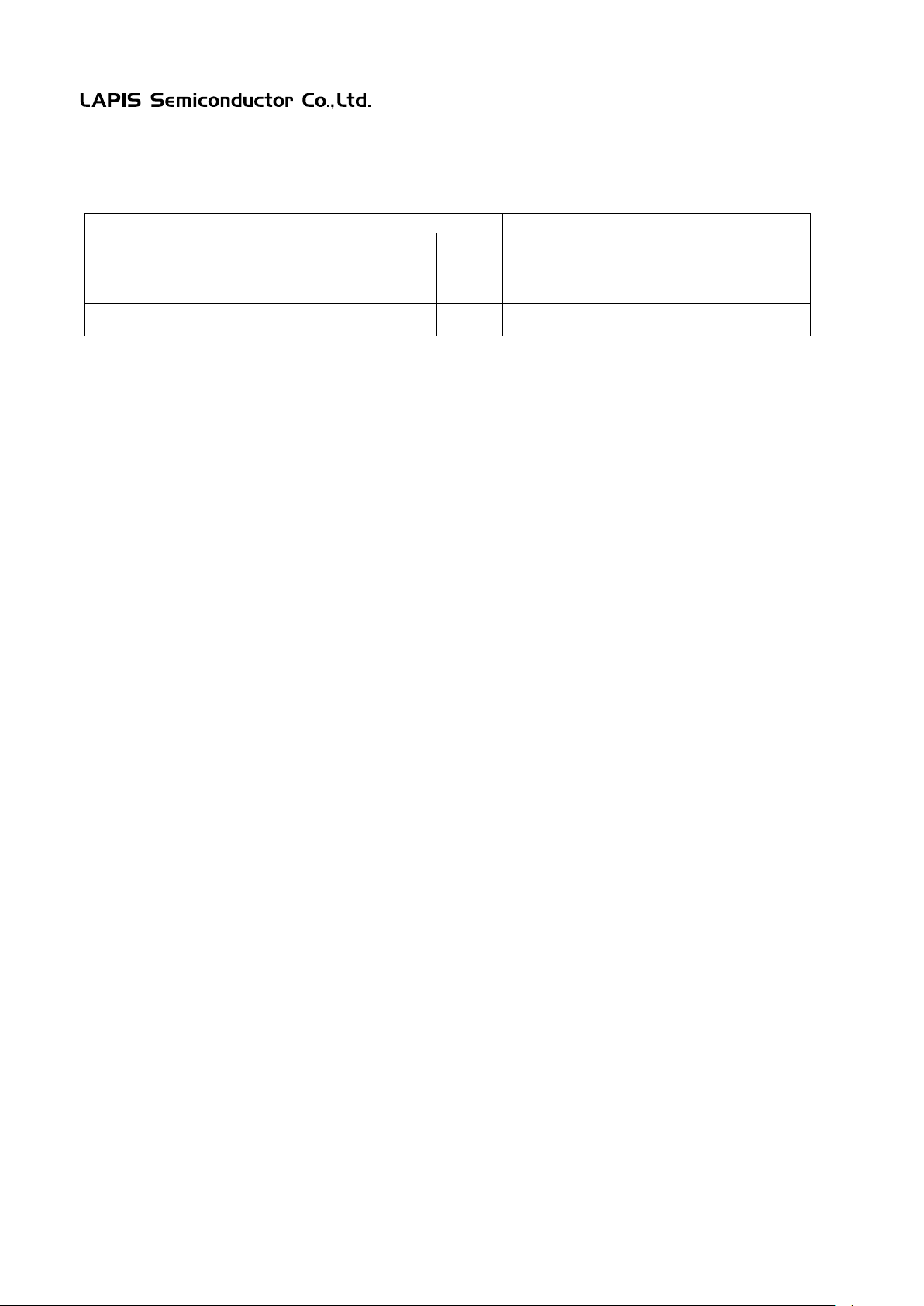
REVISION HISTORY
ML620Q150A Series Reference Board User’s Manual
FEBL620Q150ARB-02
Document
No.
FEBL620Q150ARB-01 MAY 15, 2015 – – First Edition
FEBL620Q150ARB-02 Jan 14, 2016 2 2 Update part number and add description
Date
Previous
Current
Description
FEBL620Q150ARB 27
Page 29

Mouser Electronics
Authorized Distributor
Click to View Pricing, Inventory, Delivery & Lifecycle Information:
ROHM Semiconductor:
RB-D620Q153TB48 RB-D620Q156TB52
 Loading...