

Page 1

XPort AR
User Guide
Part Number 900-405
Revision F May 2010
Page 2

Copyright and Trademark
©2009, 2010 Lantronix. All rights reserved. No part of the contents of this book may be transmitted
or reproduced in any form or by any means without the written permission of Lantronix. Printe d in
the United States of America.
Ethernet is a trademark of XEROX Corporation. UNIX is a registered trademark of The Open
Group. Windows 95, Windows 98, Windows 2000, and Windows NT are trademarks of Microsoft
Corp. Netscape is a trademark of Netscape Communications Corporation.
Warranty
For details on the Lantronix warranty replacement policy, please go to our web site at
www.lantronix.com/support/warranty.
Contacts
Lantronix Corporate Headquarters
167 Technology Drive
Irvine, CA 92618, USA
Toll Free: 800-526-8766
Phone: 949-453-3990
Fax: 949-450-7249
Technical Support
Online: www.lantronix.com/support
Sales Offices
For a current list of our domestic and international sales offices, go to the Lantronix web site at
www.lantronix.com/about/contact.
Disclaimer and Revisions
The information in this guide may change without notice. The manufacturer assumes no
responsibility for any errors that may appear in this guide. For the latest revision of this product
document, please check our online documentation at www.lantronix.com/support/documentation.
Compliance
This product has been designed to comply with the limits for a Class B digital device pursuant to
Part 15 of FCC and EN55022:1998 Rules when proper ly enclosed and groun ded. These limits are
designed to provide reasonable protection against radio interference in a residential installation.
This equipment generates, uses, and can radiate radio frequency energy, and if not installed and
used in accordance with this guide, may cause interference to radio communications. For more
information, see Compliance on page 137.
XPort AR User Guide 2
Page 3

Revision History
Date Rev. Comments
June 2005 A Initial document.
November 2005 B Added V2.0 software information.
December 2006 C Added V3.0 information.
March 2007 D Corrected pin numbers.
June 2009 E Update to firmware v4.0.0.0R16.
May 2010 F Updated for firmware release 5.1.0.0R10.
XPort AR User Guide 3
Page 4

Table of Contents
1: About This Guide 12
Chapter and Appendix Summaries ____________________________________________12
Conventions______________________________________________________________13
Additional Documentation ___________________________________________________13
2: Overview 15
Key Product Features ______________________________________________________15
Applications ______________________________________________________________15
Protocol Support __________________________________________________________16
Evolution OS™____________________________________________________________16
Software Features _________________________________________________________16
Modem Emulation ______________________________________________________16
Web-Based Configuration and Troubleshooting _______________________________16
Command-Line Interface (CLI) ____________________________________________17
SNMP Management ____________________________________________________17
XML-Based Architecture and Device Control _________________________________17
Really Simple Syndication (RSS) __________________________________________17
Enterprise-Grade Security________________________________________________17
Terminal Server/Device Management_______________________________________18
Troubleshooting Capabilities ______________________________________________18
Configuration Methods______________________________________________________18
Addresses and Port Numbers ________________________________________________19
Hardware Address______________________________________________________19
IP Address____________________________________________________________19
Port Numbers _________________________________________________________19
Product Information Label ___________________________________________________19
3: Using DeviceInstaller 21
Accessing XPort AR using DeviceInstaller___________________ ____________________21
Device Details Summary ____________________________________________________21
4: Configuration Using Web Manager 23
Accessing Web Manager____________________________________________________23
Web Manager_____________________________________________________________25
Navigating the Web Manager_________________________________________________26
5: Network Settings 28
Network 1 Interface Status___________________________________________________28
Network 1 Interface Configuration _____________________________________________29
Network 1 Ethernet Link_____________________________________________________30
XPort AR User Guide 4
Page 5

Table of Contents
6: Line and Tunnel Settings 32
Line Settings _____________________________________________________________32
Line Statistics _________________________________________________________32
Line Configuration ______________________________________________________33
Line Command Mode ___________________________________________________35
Tunnel Settings _______________________________ ____________________________36
Tunnel Statistics _______________________________________________________37
Serial Settings _________________________________________________________38
Packing Mode _________________________________________________________40
Packing Mode using Timeout __________________________________________41
Packing Mode using Send Character ____________________________________42
Accept Mode __________________________________________________________43
Connect Mode_________________________________________________________45
Disconnect Mode_______________________________________________________50
Modem Emulation ______________________________________________________51
Command Mode ____________________________________________________51
7: Terminal and Host Settings 55
Terminal Settings__________________________________________________________55
Network Terminal Configuration ___________________________________________55
Line Terminal Configuration ______________________________________________56
Host Configuration _________________________________________________________58
8: Configurable Pins Manager 60
Overview ________________________________________________________________60
Default Groups ________________________________________________________60
Custom Groups ________________________________________________________60
Configurable Pins__________________________________________________________60
Change CPs __________________________________________________________61
CPM Groups _____________________________________________________________63
View CP Group Status___________________________________________________63
Add Custom CP Groups _________________________________________________63
Remove Custom CP Groups______________________________________________65
Remove CPs from CP Groups_____________________________________________65
9: Services Settings 66
DNS Status and Cache _____________________________________________________66
PPP Configuration _________________________________________________________67
SNMP Configuration _______________________________________________________69
FTP ____________________________________________________________________71
TFTP ___________________________________________________________________72
Syslog __________________________________________________________________73
HTTP ___________________________________________________________________75
HTTP Statistics ________________________________________________________75
XPort AR User Guide 5
Page 6

Table of Contents
HTTP Configuration_____________________________________________________76
HTTP Authentication ________________________________________ ____________78
RSS ____________________________________________________________________79
10: Security Settings 81
SSH Server Host Keys______________________________________________________81
SSH Server Authorized Users ________________________________________________83
SSH Client Known Hosts ____________________________________________________85
SSH Client Users__________________________________________________________86
SSL Cipher Suites _________________________________________________________88
SSL Certificates ___________________________________________________________89
SSL RSA or DSA __________________________________________________________89
SSL Certificates and Private Keys_____________________________________________90
SSL Utilities ______________________________________________________________90
SSL Configuration _________________________________________________________91
11: Maintenance and Diagnostics Settings 94
Filesystem _______________________________________________________________94
Filesystem Statistics and Actions __________________________________________94
Filesystem Browser_____________________________________________________95
Protocol Stack ____________________________________________________________98
TCP _________________________________________________________________98
IP ___________________________________________________________________ 99
ICMP _______________________________________________________________100
ARP ________________________________________________________________101
IP Address Filter__________________________________________________________102
Query Port ______________________________________________________________103
Diagnostics______________________________________________________________104
Hardware____________________________________________________________104
MIB-II_______________________________________________________________105
IP Sockets ___________________________________________________________ 107
Ping ________________________________________________________________107
Traceroute___________________________________________________________109
DNS Lookup _________________________________________________________110
Memory _____________________________________________________________111
Buffer Pools__________________________________________________________112
Processes ___________________________________________________________112
System_________________________________________________________________114
12: Advanced Settings 116
Email Statistics___________________________________________________________116
Email Configuration _______________________________________________________117
XPort AR User Guide 6
Page 7

Table of Contents
Command Line Interface ___________________________________________________118
CLI Statistics _________________________________________________________119
CLI Configuration______________________________________________________119
XML Configuration ________________________________________________________121
XML Export Configuration _______________________________________________121
XML Export Status_____________________________________________________123
XML Import Configuration _______________________________________________125
Import Configuration from External File _________________________________125
Import Configuration from Filesystem___________________________________126
Import Line(s) from Single Line Settings on the Filesystem __________________128
13: Branding the XPort AR 131
Web Manager Customization________________________________________________131
Short and Long Name Customization _________________________________________131
14: Updating Firmware 133
A: Technical Support 134
B: Binary to Hexadecimal Conversions 135
Converting Binary to Hexadecimal____________________________________________135
Conversion Table _____________________________________________________135
Scientific Calculator____________________________________________________136
C: Compliance 137
Declaration of Conformity___________________________________________________137
RoHS Notice ______________________ ______________________________________138
Index 140
XPort AR User Guide 7
Page 8

List of Figures
Figure 2-1 XPort AR Product Information Label _________________________________________20
Figure 4-1 XPort AR Web Manager Home Page ________________________________________24
Figure 4-2 Components of a Typical Web Manager Page _________________________________25
Figure 5-1 Network 1 (eth0) Interface Status Web Page __________________________________28
Figure 5-2 Network 1 (eth0) Interface Configuration Web Page_____________________________29
Figure 5-3 Network 1 (eth0) Ethernet Link Web Page ____________________________________31
Figure 6-1 Line 1 Statistics Web Page ______________________ __________________________33
Figure 6-2 Line 1 Configuration Web Page_____________________________________________34
Figure 6-3 Line 1 Command Mode Web Page __________________________________________35
Figure 6-4 Tunnel 1 Statistics Web Page ______________________________________________38
Figure 6-5 Tunnel 1 Serial Settings Web Page__________________________________________39
Figure 6-6 Tunnel 1 Packing Mode Web Page__________________________________________40
Figure 6-7 Tunnel 1 Packing Mode (Timeout)___________________________________________ 41
Figure 6-8 Tunnel 1 Packing Mode (Send Character) ____________________________________42
Figure 6-9 Tunnel 1 Accept Mode Web Page___________________________________________44
Figure 6-10 Tunnel 1 Connect Mode Page___________________________ __________________47
Figure 6-11 Tunnel 1 Disconnect Mode Web Page ______________________________________50
Figure 6-12 Tunnel 1 Modem Emulation Web Page______________________________________53
Figure 7-1 Terminal on Network Configuration Web Page_________________________________55
Figure 7-2 Terminal on Line 1 Configuration Web Page___________________________________57
Figure 7-3 Host Configuration Web Page______________________________________________58
Figure 8-1 CPM CPs Page _________________________________________________________61
Figure 8-2 CPM Groups Page_______________________________________________________64
Figure 9-1 DNS Status and Cache Web Page __________________________________________67
Figure 9-2 PPP Configuration Web Page______________________________________________68
Figure 9-3 SNMP Web Page________________________________________________________70
Figure 9-4 FTP Web Page _________________________________________________________71
Figure 9-5 TFTP Server Web Page __________________________________________________72
Figure 9-6 Syslog Web Page _______________________________________________________74
Figure 9-7 HTTP Statistics Web Page ________________________________________________75
Figure 9-8 HTTP Configuration Web Page_____________________________________________76
Figure 9-9 HTTP Authentication Web Page ____________________________________________78
Figure 9-10 RSS Web Page ________________________________________________________80
Figure 10-1 SSH Server Host Keys Web Page__________________________________________82
Figure 10-2 SSH Server Authorized Users Web Page____________________________________84
Figure 10-3 SSH Client Known Hosts Web Page________________________________________85
Figure 10-4 SSH Client Users Web Page______________________________________________87
Figure 10-5 SSL Web Page ________________________________________________________91
Figure 11-1 Filesystem Statistics Web Page ___________________________________________95
Figure 11-2 Filesystem Browser Web Page ____________________________________________96
Figure 11-3 TCP Web Page________________________________________________________98
XPort AR User Guide 8
Page 9

List of Figures
Figure 11-4 IP Web Page __________________________________________________________99
Figure 11-5 ICMP Web Page ______________________________________________________100
Figure 11-6 ARP Web Page _______________________________________________________101
Figure 11-7 IP Address Filter Web Page _____________________________________________102
Figure 11-8 Query Port Web Page __________________________________________________103
Figure 11-9 Diagnostics Hardware Web Page _________________________________________105
Figure 11-10 MIB-II Network Statistics Web Page ______________________________________106
Figure 11-11 IP Sockets Web Page _________________________________________________107
Figure 11-12 Ping Web Page ___________________________________________________ ___108
Figure 11-13 Traceroute Web Page ______________________________________ ___________109
Figure 11-14 DNS Lookup Web Page________________________________________________110
Figure 11-15 Memory Web Page ___________________________________________________111
Figure 11-16 Buffer Pools Web Page________________________________________________112
Figure 11-17 Processes Web Page _________________________________________________113
Figure 11-18 System Web Page____________________________________________________114
Figure 12-1 Email Statistics Web Page_______________________________________________116
Figure 12-2 Email 1 Configuration Web Page__________________________________________117
Figure 12-3 CLI Statistics Web Page ________________________________________________119
Figure 12-4 CLI Configuration Web Page_____________________________________________120
Figure 12-5 XML Export Configuration Web Page ______________________________________122
Figure 12-6 XML Export Status Web Page____________________________________________124
Figure 12-7 Import Configuration Web Page __________________________________________125
Figure 12-8 Import Configuration from External File Web Page____________________________126
Figure 12-9 Import Configuration from Filesystem Web Page _____________________________127
Figure 12-10 Import Lines from Single Line Settings on the Filesystem Web Page_____________129
Figure 13-1 System Branding Web Page __________________________________________ ___132
Figure 14-1 System Web Page_____________________________________________________133
Figure B-1 Scientific Calculator_____________________________________________________136
Figure B-2 Hex Display__________________________________ _________________________136
XPort AR User Guide 9
Page 10

List of Tables
Table 1-1 Chapter/Appendix and Summary ____________________________________________12
Table 1-2 Conventions Used in This Book _____________________________________________13
Table 3-1 Current Settings and Description ____________________________________________21
Table 4-1 Summary of Web Manager Pages ___________________________________________26
Table 5-1 Network 1 Interface Configuration Fields ______________________________________29
Table 5-2 Network 1 (eth0) Ethernet Link Fields_________________________________________31
Table 6-1 Line 1 Configuration Fields_________________________________________________34
Table 6-2 Line 1 Command Mode Fields ______________________________________________36
Table 6-3 Tunnel 1 Serial Settings Fields______________________________________________39
Table 6-4 Tunnel Packing Mode (Timeout) Fields _______________________________________41
Table 6-5 Tunnel Packing Mode (Send Character) Fields _________________________________42
Table 6-6 Tunnel Accept Mode Fields ________________________________________________44
Table 6-7 Tunnel 1 Connect Mode Fields______________________________________________47
Table 6-8 Tunnel Disconnect Mode Fields _____________________________________________ 51
Table 6-9 Modem Emulation Commands and Descriptions ________________________________51
Table 6-10 Tunnel Modem Emulation Fields ___________________________________________53
Table 7-1 Terminal on Network Configuration Fields _____________________________________56
Table 7-2 Terminal on Line 1 Configuration Fields_______________________________________57
Table 7-3 Host Configuration Fields __________________________________________________59
Table 8-1 CPM CPs Current Configuration Fields and Descriptions _________________________61
Table 8-2 CPM CPs Status Fields and Descriptions______________________________________62
Table 8-3 CPM Group Status Fields and Descriptions ____________________________________63
Table 8-4 CPM Groups Current Configuration Fields and Descriptions_______________________64
Table 9-1 PPP Configuration Fields __________________________________________________69
Table 9-2 SNMP Fields____________________________________________________________70
Table 9-3 FTP Fields______________________________________________________________72
Table 9-4 TFTP Server Fields_______________________________________________________ 73
Table 9-5 Syslog Fields____________________________________________________________74
Table 9-6 HTTP Configuration Fields _________________________________________________77
Table 9-7 HTTP Authentication Fields ________________________________________________78
Table 9-8 RSS Fields _____________________________________________________________80
Table 10-1 SSH Server Host Keys Fields______________________________________________82
Table 10-2 SSH Server Authorized Users Fields ________________________________________84
Table 10-3 SSH Client Known Hosts Fields ____________________________________________85
Table 10-4 SSH Client Users Fields__________________________________________________87
Table 10-5 Supported Cipher Suites__________________________________________________88
Table 10-6 SSL Fields_____________________________________________________________92
Table 11-1 Filesystem Browser Fields ________________________________________________97
Table 11-2 TCP Fields _____________________ ________________________________ _______98
Table 11-3 ARP Web Page Fields __________________________________________________101
Table 11-4 IP Address Filter Fields__________________________________________________103
XPort AR User Guide 10
Page 11

List of Tables
Table 11-5 Ping Fields ___________________________________________________________108
Table 11-6 Traceroute Fields ______________________________________________________109
Table 11-7 DNS Lookup Fields_____________________________________________________111
Table 11-8 System Fields_________________________________________________________115
Table 12-1 Email 1 Configuration Fields______________________________________________118
Table 12-2 CLI Configuration Fields_________________________________________________120
Table 12-3 XML Export Configuration Fields __________________________________________122
Table 12-4 XML Export Status Fields ________________________________________________124
Table 12-5 Import Configuration from Filesystem Fields _________________________________128
Table 12-6 Import Lines from Single Line Settings Fields_________________________________129
Table B-1 Conversion Values______________________________________________________135
XPort AR User Guide 11
Page 12

1: About This Guide
This guide describes how to configure, use, and update the XPort AR. It is for software developers
and original equipment manufacturers who are embedding the XPort AR in their designs. This
chapter contains the following sections:
Chapter and Appendix Summaries
Conventions
Additional Documentation
Chapter and Appendix Summaries
Table 1-1 lists and summarizes each chapter and appendix.
Table 1-1 Chapter/Appendix and Summary
Chapter/Appendix Summary
2: Overview
3: Using DeviceInstaller
4: Configuration Using Web Manager
5: Network Settings
6: Line and Tunnel Settings
7: Terminal and Host Settings
8: Configurable Pins Manager
9: Services Settings
10: Security Settings
Main features of the product and the protocols it
supports. Includes technical specifications.
Instructions for viewing the current configuration using
DeviceInstaller.
Instructions for accessing Web Manager and using it to
configure settings for the XPort AR.
Instructions for using the web interface to configure
Ethernet settings.
Instructions for using the web interface to configure
lines and tunnels.
Instructions for using the web interface to configure
terminals and host settings.
Instructions for using the Configurable Pins Manager
(CPM) to set up the configurable pins to work with a
device.
Instructions for using the web interface to configure
settings for DNS, SNMP, FTP, and other services.
Description and configuration of SSH and SSL security
settings and instructions for using the web interface to
configure SSH and SSL security settings.
11: Maintenance and Diagnostics Settings
12: Advanced Settings
13: Branding the XPort AR
14: Updating Firmware
Instructions for using the web interface to maintain the
XPort AR, view statistics, files, and logs, and diagnose
problems.
Instructions for using the web interface to configure
email, CLI, and XML settings.
Description of PPP on the XPort AR.
Instructions for obtaining the latest firmware and
updating the XPort AR.
XPort AR User Guide 12
Page 13

Table 1-1 Chapter/Appendix and Summary (continued)
Chapter/Appendix Summary
1: About This Guide
A: Technical Support
B: Binary to Hexadecimal Conversions
C: Compliance
Conventions
Table 1-2 lists and describes the conventions used in this book.
Table 1-2 Conventions Used in This Book
Convention Description
Bold text Default parameters.
Brackets [ ] Optional parameters.
Angle Brackets < > Possible values for parameters.
Pipe | Choice of parameters.
Warning Warning: Means that you are in a situation that could
Instructions for contacting Lantronix Technical Support.
Instructions for converting binary values to
hexadecimals.
Lantronix compliance information.
cause equipment damage or bodily injury. Befo re you work
on any equipment, you must be aware of the hazards
involved with electrical circuitry and familiar with standard
practices for preventing accidents.
Note Note: Means take notice. Notes contain helpful suggestions,
information, or references to material not covered in the publication.
Caution Caution: Means you might do something that could result in faulty
equipment operation, or loss of data.
Screen Font
(Courier New)
CLI terminal sessions and examples of CLI input.
Additional Documentation
Visit the Lantronix web site at www.lantronix.com/support/documentation for the latest
documentation and the following additional documentation.
XPort AR Integration Guide—Information about the XPort AR hardware, the XPort AR
evaluation board, and integrating the XPort AR into your product.
XPort AR Command Reference—Instru ctions for accessing Command Mode ( the command
line interface) using a Telnet connection or through the serial port. Detailed information about
the commands. Also provides details for XML configuration and status.
XPort AR Getting Started Guide—Instructions for getting the XPort AR on the evaluation
board up and running.
DeviceInstaller Online Help—Instructions for using the Lantronix Windows-based utility to
locate the XPort AR and to view its current settings.
XPort AR User Guide 13
Page 14

1: About This Guide
Com Port Redirector Quick Start and Online Help—Instructions for using the Lantronix
Windows-based utility to create virtual com ports.
Secure Com Port Redirector User Guide—Instructions for using the Lantronix Windows-
based utility to create secure virtual com ports.
XPort AR User Guide 14
Page 15

2: Overview
The XPort AR embedded Ethernet Device Server is a complete network–enabling solution on a
1.75” x 1.75” PCB. This miniature device server empowers original equipment manufacturers
(OEMs) to go to market quickly and easily with Ethernet networking and web page serving
capabilities built into their products.
This chapter contains the following sections:
Key Product Features
Applications
Protocol Support
Evolution OS™
Software Features
Configuration Methods
Addresses and Port Numbers
Product Information Label
Key Product Features
The XPort AR is designed with additional features above and beyond the original XPort, including:
The Evolution OS operating system.
Two full serial ports with all hardware handshaking signals or three serial ports without
handshaking signals.
Eleven configurab le pins .
Fully compliant PoE designs by using PoE compliant magnetics and passing through b oth the
used and unused pairs.
Increased memory: 4MB Flash and 1.25MB RAM.
Applications
The XPort AR device server connects serial devices, such as those listed below to Ethernet
networks using the IP protocol family:
CNC controllers
Data collection devices
Universal Power Supply (UPS) management unit
Telecommunications equipment
Handheld instruments
Security, alarm, an d acce ss control devices
Patient monitoring equipment
Medical instrumen tation
Industrial Manufacturing/Automation systems
XPort AR User Guide 15
Page 16

Building Automation equipment
Point of Sale Systems
ATM machines
Data display devices
Modems
Time/attendance clocks and terminals
Protocol Support
The XPort AR device server supports the following TCP/IP protocols:
ARP, IP, UDP, TCP, ICMP, BOOTP, DHCP, Auto IP, Telnet, DNS, FTP, TFTP, HTTP/HTTPS,
SSH, SSL/TLS, SNMP, SMTP, RSS, PPP and Syslog for network communications and
management.
TCP, UDP, TCP/AES, UDP/AES, Telnet, SSH and SSL/TLS for tunneling to the serial port.
TFTP, FTP, and HTTP for firmware upgrades and uploading files.
Evolution OS™
2: Overview
The XPort AR features the Lantronix Evolution OS™. Key features of the Evolution OS™ include:
Built-in Web server for configuration and troubleshooting from Web-based browsers
CLI configurability
SNMP management
XML data transport and configurability
Really Simple Syndication (RSS) information feeds
Enterprise-grade security with SSL and SSH
Comprehensive troubleshooting tools
Software Features
Modem Emulation
In modem emulation mode, the XPort AR can replace dial-up modems. The unit accepts modem
AT commands on the serial port, and then establishes a network connection to the end device,
leveraging network connections and bandwidth to eliminate dedicated modems and phone lines.
Web-Based Configuration and Troubleshooting
Built upon Internet-based standards, the XPort AR enables configuration, management, and
troubleshooting by using a browser-ba se d inte r fac e accessible anytime from anywhere. All
configuration and troubleshooting options are available via the web interface. You can access all
functions via a Web browser, for remote access. As a result, you de crease downtime (using the
troubleshooting tools) and implement configuration changes (using the configuration tools).
XPort AR User Guide 16
Page 17

2: Overview
Command-Line Interface (CLI)
Making the edge-to-enterprise vision a reality, the XPort AR with Evolution OS™ uses industrystandard tools for configuration, communication, and control. For example, the Evolution OS™
uses a Command Line Interface (CLI) whose syntax is very similar to that used by data center
equipment such as routers and hubs.
SNMP Management
The XPort AR supports full SNMP management, making it ideal for applications where device
management and monitoring are critical. These features allow networks with SNMP capabilities to
correctly diagnose and monitor XPort AR.
XML-Based Architecture and Device Control
XML is a fundamental building block for the future growth of M2M networks. The XPort AR
supports XML-based configuration setup records that make device configuration transparent to
users and administrators. The XML is easily editable with a standard text or XML editor.
Really Simple Syndication (RSS)
The XPort AR supports Really Simple Syndication (RSS) for streaming and managing on-line
content. RSS feeds all the configuration changes that occur on the device. An RSS aggregator can
be used to monitor many RSS feeds at one time. More powerful than simple email alerts, RSS
uses XML as an underlying Web page transport and adds intelligenc e to the networked device,
while not taxing already overloaded email systems.
Enterprise-Grade Security
Evolution OS™ provides the XPort AR the highest level of networking security possible. This ‘data
center grade’ protection ensures that each device on the M2M network carries the same level of
security as traditional IT networking equipment in the corporate data center.
By protecting the privacy of serial data transmitted across public networks, users can maintain
their existing investment in serial technology, while taking advantage o f the highest data-protection
levels possible.
SSH and SSL can:
Verify the data received came from the proper source.
Validate that the data transferred from the source over the network has not changed when it
arrives at its destination (shared secret and hashing).
Encrypt d ata to protect it from prying eyes and nefarious individuals.
Provide the ability to run popular M2M protocols over a secure SSH or SSL connection.
In addition to keeping data safe and accessible, the XPort AR has robust defenses to hostile
Internet attacks such as denial of service (DoS), which can be used to take down the network.
Moreover, the XPort AR cannot be used to bring down other devices on the network.
XPort AR User Guide 17
Page 18

2: Overview
You can use the XPort AR with the Lantronix Secure Com Port Redirector (SCPR) to encrypt COM
port-based communications between PCs and virtually any electron ic device. SCPR is a Windows
application that creates a secure communications p ath ov er a netwo rk b etween the co mpu ter and
serial-based devices that are traditionally controlled via a COM port. With SCPR installed at each
computer, computers that were formerly “hard-wired” by serial cabling for security purposes or to
accommodate applications that only understood serial data can instead communicate over an
Ethernet network or the Internet.
Terminal Server/Device Management
Remote offices can have routers, PBXs, servers and other networking equipment that require
remote management from the corporate facility. The XPort AR easily attaches to the serial ports
on a server, Private Branch Exchange (PBX), or other networking equipment to deliver central,
remote monitoring and management capability.
With the Login Connect Menu feature on the XPort AR, connections to the console ports of the
attached devices as well as Ethernet hosts, such as Unix servers or another XPort AR, can easily
be picked from a user-defined menu. This allows console ports across multiple devices to be
accessed from one XPort AR.
Troubleshooting Capabilities
The XPort AR offers a comprehensive diagnostic toolset that lets you troubleshoot problems
quickly and easily. Available from the Web Manager, CLI, and XML interfaces, th e diagnostic tools
let you:
View critical hardware, memory, MIB-II, buffer pool, and IP socket info rmation.
Perform ping and traceroute operations.
Conduct forward or backup DNS lookup operations.
View all processes currently running on the XPort AR, including CPU utilization and total stack
space available.
Configuration Methods
After installation, the XPort AR requires configuration. For the unit to operate correctly on a
network, it must have a unique IP address on the network. There are four basic methods for
logging into the XPort AR and assigning IP addresses and other configurable settings:
DeviceInstaller—Configure the IP address and related settings and view current settings on
the XPort AR using a PC GUI attached to a network. See Using DeviceInstaller on page 21.
Web Manager—Use a web browser to configure the XPort AR settings using the Lantro nix
Web Manager. See Configuration Using Web Manager on page 23.
Command Line Interface (CLI)—There are two methods for accessing CLI: making a Telnet
connection or connecting a terminal (or a PC running a terminal emulation program) to the
serial port. Refer to the XPort AR Command Reference for instructions and available
commands.
XML—The XPort AR supports XML-based configuration and setup records that make device
configuration transparent to users and administrators. XML is easily editable with a standard
text or XML editor. Refer to the XPort AR Command Reference for instructions and available
commands.
XPort AR User Guide 18
Page 19

Addresses and Port Numbers
Hardware Address
The hardware address is also referred to as the Ethernet address or M AC addre s s. The first thr ee
bytes of the Ethernet address are fixed and read 00-20-4A, identifying the unit as a Lantronix
product. The fourth, fifth, and sixth bytes are unique numbers a ssigned to each unit. T he following
sample shows a hardware address:
00-20-4A-14-01-18
or
00:20:4A:14:01:18
IP Address
Every device connected to an IP network must have a unique IP add ress. This address references
the specific unit.
Port Numbers
Every TCP connection and every UDP datagram is defined by a destination and source IP
address, and a destination and source port nu mber. For example, a Telnet serv er commonly u ses
port number 23.
2: Overview
The following is a list of the default server port numbers running on the XPort AR:
TCP Port 22—SSH Server (Command Mode configuration)
TCP Port 23—Telnet Server (Command Mode configuration)
TCP Port 80—HTTP (Web Manager configuration)
TCP Port 443—HTTPS (Web Manager configuration)
UDP Port 161—SNMP
TCP Port 21—FTP
UDP Port 69—TFTP
UDP Port 30718—LDP (Lantronix Discovery Protocol) port
TCP/UDP Port 10001—Tunnel 1
TCP/UDP Port 10002—Tunnel 2
Product Information Label
Figure 2-1 shows th e bo tto m of eac h un it whic h ha s a product information label. The label
contains the following information:
Product ID (name)
Product description
XPort AR User Guide 19
Page 20
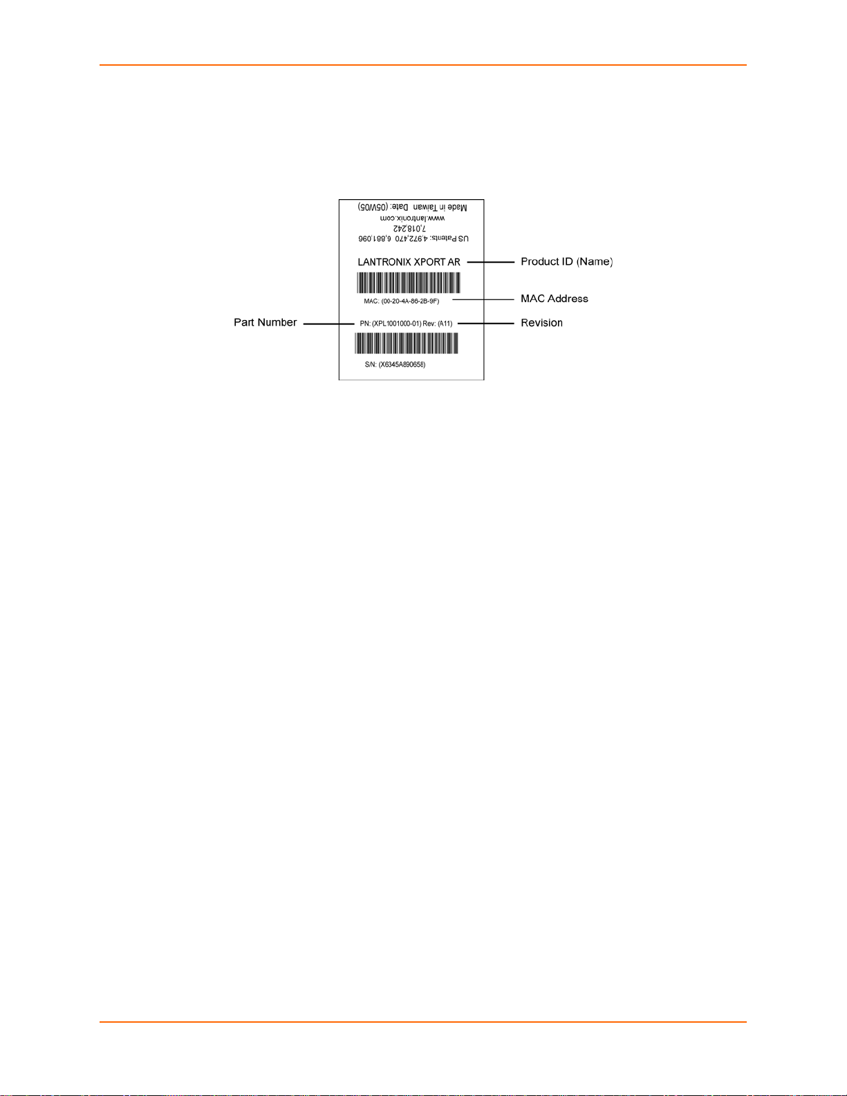
2: Overview
Bar code
Part number
Serial number (which is the hardware address, also referred to as Ethernet or MAC address)
Figure 2-1 XPort AR Product Information Label
XPort AR User Guide 20
Page 21

3: Using DeviceInstaller
This chapter covers the steps for locating a XPort AR unit and viewing its properties and device
details. It contains the following sections:
Accessing XPort AR using DeviceInstaller
Device Details Summary
DeviceInstaller is a free utility program provided by Lantronix that discovers, configures, upgrades,
and manages Lantronix Device Servers. It can be downloaded from the Lantronix website at
www.lantronix.com/support/downloads. For instructions on using DeviceInstaller to configure the
IP address and related settings or for more advanced features, see the DeviceInstaller online
Help.
Note: AutoIP generates a random IP address in the range of 169.254.0.1 to
169.254.255.254 if no BOOTP or DHCP server is found.
Accessing XPort AR using DeviceInstaller
Note: Keep a record of the MAC address because the MAC address is required to
locate the XPort AR using DeviceInstaller.
1. Click Start > All Programs > Lantronix > DeviceInstaller > DeviceInstaller. When
DeviceInstaller starts, it performs a network device search. To perform another search, click
the Search button.
2. Expand the XPort folder by clicking the plus (+) symbol next to the folder icon. The list of
available Lantronix XPort devices displays.
3. Select the XPort AR by expanding its entry and clicking on its hardware (MAC) address to
view its configuration.
4. Click the Device Details tab, on the right. The current XPort AR configuration displays. This is
only a subset of the complete configuration; access the complete configuration by using the
Web Manager, CLI, or XML.
Device Details Summary
Table 3-1 lists and describes the display only settings unless otherwise noted.
Table 3-1 Current Settings and Description
Current Settings Description
Name Name identifying the XPort AR.
Group Configurable field. Enter a group to categorize the XPort AR.
Comments Configurable field. Enter comments for the XPort AR. Double-click
Double-click the field, type in the value, and press Enter to complete.
This group name is local to this PC and is not visible on other PCs or
laptops using DeviceInstaller.
the field, type in the value, and press Enter to complete. This
description or comment is local to this PC and is not visible on other
PCs or laptops using DeviceInstaller.
XPort AR User Guide 21
Page 22

3: Using DeviceInstaller
Table 3-1 Current Settings and Description (continued)
Current Settings Description
Device Family Shows the XPort AR device family type as “XPort”.
Type Shows the device type as XPort AR.
ID Shows the XPort AR ID embedded within the unit.
Hardware Address Shows the XPort AR hardware (MAC) address.
Firmware Version Shows the firmware currently installed on the XPor t AR.
Extended Firmware Version Provides additional information on the firmware version.
Online Status Shows the XPort AR status as Online, Offline, Unreachable (the XPort
AR is on a different subnet), or Busy (the XPort AR is currently
performing a task).
IP Address Shows the XPort AR current IP address. To change the IP address,
click the Assign IP button on the DeviceInstaller menu bar.
IP Address was Obtained Displays dynamically if the XPort AR automatically received an IP
address (e.g., from DHCP). Displays statically if the IP address was
configured manually.
If the IP address was assigned dynamically, the following fields
appear:
Obtain via DHCP with values of True or False.
Obtain via BOOTP with values of True or False.
Subnet Mask Shows the subnet mask specifying the network segment on which the
XPort AR resides.
Gateway Shows the IP address of the router of this network. There is no default.
Number of Ports Shows the number of serial ports on this XPort AR.
Supports Configurable Pins Shows True, indicating that configurable pins are available on the
XPort AR.
Supports Email Triggers Shows True, indicating email triggers are available on the XPort AR.
Telnet Enabled Indicates whether Telnet is enabled on this XPort AR.
Telnet Port Shows the XPort AR port for Telnet sessions.
Web Enabled Indicates whether Web Manager access is enabled on this XPort AR.
Web Port Shows the XPort AR port for Web Manager configuration.
Firmware Upgradeable Shows True, indicating the XPort AR firmware is upgradeable as
newer versions become available.
XPort AR User Guide 22
Page 23

4: Configuration Using Web Manager
This chapter describes how to configure the XPort AR by using Web Manager, the Lantronix
browser-based configuration tool. The con fig ur ation is stored in nonvolatile memory and is
retained without power. All changes take effect imm e diate l y, un less oth e rwis e no te d. It cont ain s
the following sections:
Accessing Web Manager
Web Manager
Navigating the Web Manager
Accessing Web Manager
Note: You can also access the Web Manager by selecting the Web Configuration ta b on
the DeviceInstaller window.
To access the Web Manager, perform the following steps.
1. Open a standard web browser. Lantronix supports the latest version of Internet Explorer,
Mozilla Suite, Mozilla Firefox, Safari, or Opera.
2. Enter the IP address of the XPort AR in the address bar. The IP address may have been
assigned manually using DeviceInstaller or the serial port (see the XPort AR Demo Kit Quick
Start Guide) or automatically by DHCP.
3. Enter your username and password.The factory-default username is “admin” and the factory–
default password is “PASS.” The Device Status web page shown in Figure 4-1 displays
configuration, network settings, line settings, tunneling settings, and product information.
XPort AR User Guide 23
Page 24

4: Configuration Using Web Manager
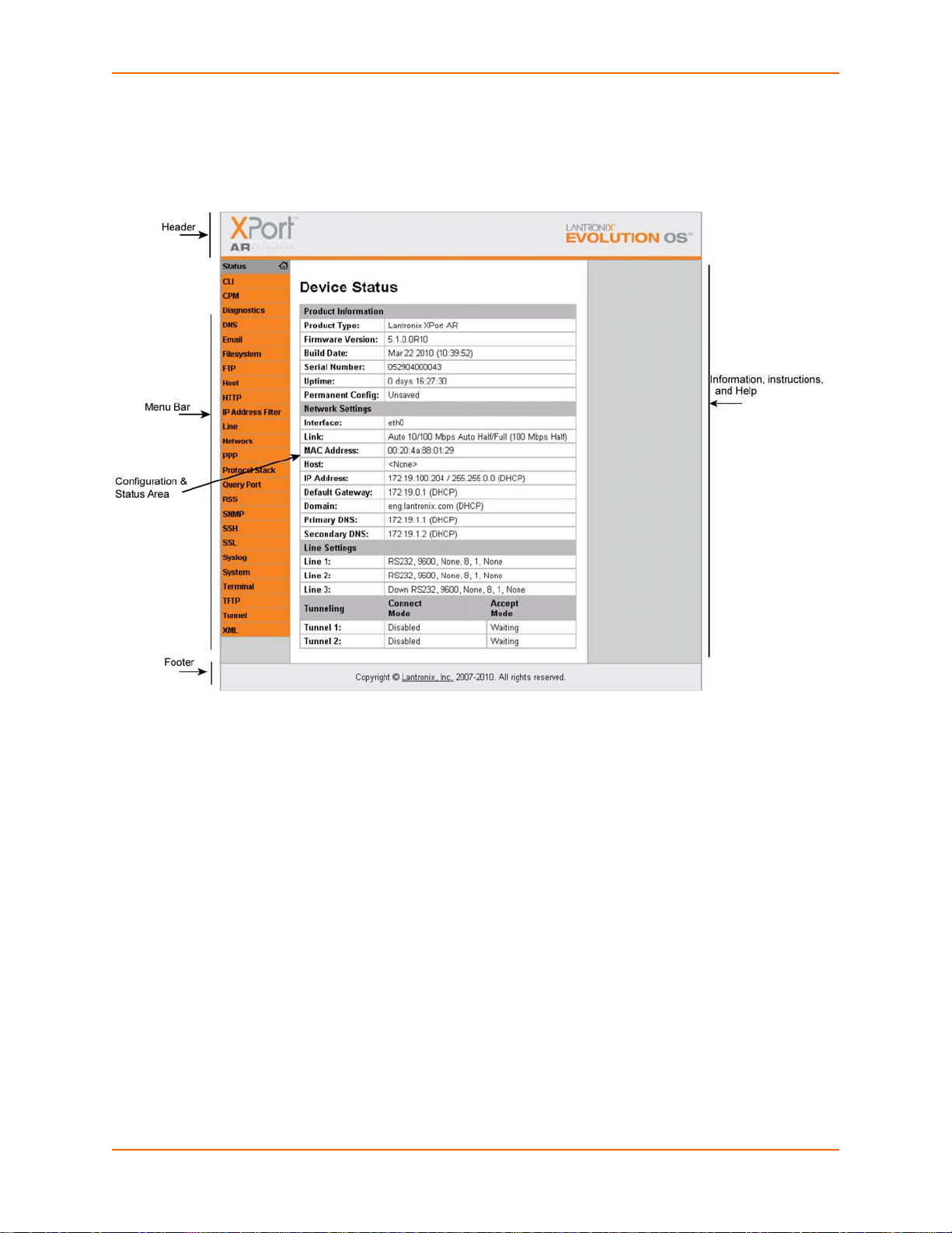
The Home page is also the Device Status page which appea rs af te r you log int o th e Web
Manager. It also appears when you click Status in the Main Menu.
Figure 4-1 XPort AR Web Manager Home Page
XPort AR User Guide 24
Page 25
Web Manager
Figure 4-2 shows the components of a typical Web Manager page.
Figure 4-2 Components of a Typical Web Manager Page
4: Configuration Using Web Manager
The Menu Bar (orange) always appears at the left side of the web page. There are accessible
sections listed in the Main Menu, such as CLI, Diagnostics, Protocol Stack, etc. To display one of
these sections, click it.
The Help displays on the right side of the web page and contains information or instructions
associated with the page.
The center of a web page contains the following additional sections:
At the top, there are links to configurable fields. The links often indicate the configurable field,
for example, Line, Host, or Tunnel.
In the middle, you can select or enter new configuration settings. Some pages display
statistics or status in this area rather than allow you to enter settings.
At the bottom, the curren t configuration displays. In some cases, you can reset or clear a
setting.
At the very bottom, the copyri ght information displays with a link to the Lantronix home page.
XPort AR User Guide 25
Page 26

Navigating the Web Manager
The Web Manager provides an intuitive point-and-click interface. A menu bar on the left side of
each page provides links you can click to navigate from one page to another. Some pages are
read-only, while others let you change configuration settings.
Note: There may be times when you must reboot the XPort AR for the new configuration
settings to take effect. The chapters that follow indicate when a change requires a re boot.
Table 4-1 Summary of Web Manager Pages
Web Manager Page Description Page
4: Configuration Using Web Manager
Status Shows product information and network, line, and tunneling
settings.
CLI Shows Command Line Interface (CLI) statistics and lets you
change the current CLI configuration settings.
CPM Shows information about the Configurable Pins Manager (CPM)
and how to set the configurable pins and pin groups to work with
a device.
Diagnostics Lets you perform various diagnostic procedures.
DNS Shows the current configuration of the DNS subsystem and the
DNS cache.
Email Shows email statistics and lets you clear the email log, configure
email settings, and send an email.
Filesystem Shows file system statistics and lets you browse the file system
to view a file, create a file or directory, upload files using HTTP,
copy a file, move a file, or perform TFTP actions.
FTP Shows statistics and lets you change the current configuration for
the File Transfer Protocol (FTP) server.
Host Lets you view and change settings for a host on the network.
HTTP Shows HyperText Transfer Protocol (HTTP) statistics and lets
you change the current configuration and authentication settings.
24
118
60
94
67
116
95
71
58
75
IP Address Filter Lets you specify all the IP addresses and subnets that are
allowed to send data to this device.
Line Shows statistics and lets you change the current configuration
and Command mode settings of a serial line.
Network Shows status and lets you configure the network interface.
PPP Lets you configure a network link using Point-to-Point Protocol
(PPP) over a serial line.
Protocol Stack Lets you perform lower level network stack-specific activities.
Query Port Lets you change configuration settings for the query port.
RSS Lets you change current Really Simple Syndication (RSS)
settings.
102
32
29
68
98
103
80
XPort AR User Guide 26
Page 27

4: Configuration Using Web Manager
Table 4-1 Summary of Web Manager Pages (continued)
Web Manager Page Description Page
SNMP Lets you change the current Simple Network Management
Protocol (SNMP) configuration settings.
SSH Lets you change the configuration settings for SSH server host
keys, SSH server authorized users, SSH client known hosts, and
SSH client users.
SSL Lets you upload an existing certificate or create a new self-signed
certificate.
Syslog Lets you specify the severity of events to log and the server and
ports to which the syslog should be sent.
System Lets you rebo ot the XPort AR, restore factory defaults, upload
new firmware, and change the XPort AR long and short names.
Terminal Lets you change current settings for a terminal.
TFTP Shows statistics and lets you change the current configuration for
the Trivial File Transfer Protocol (TFTP) server.
Tunnel Lets you change the current configuration settings for a tunnel.
XML Lets you export XML configuration and status records, and
import XML configuration records.
70
82
91
74
114
55
72
36
121
XPort AR User Guide 27
Page 28
5: Network Settings
This chapter describes how to access, view, and configure network settings from the Network web
page. The Network web page contains sub-menus that enable you to view and configure the
aspects of your network.
This chapter contains the following sections:
Network 1 Interface Status
Network 1 Interface Configuration
Network 1 Ethernet Link
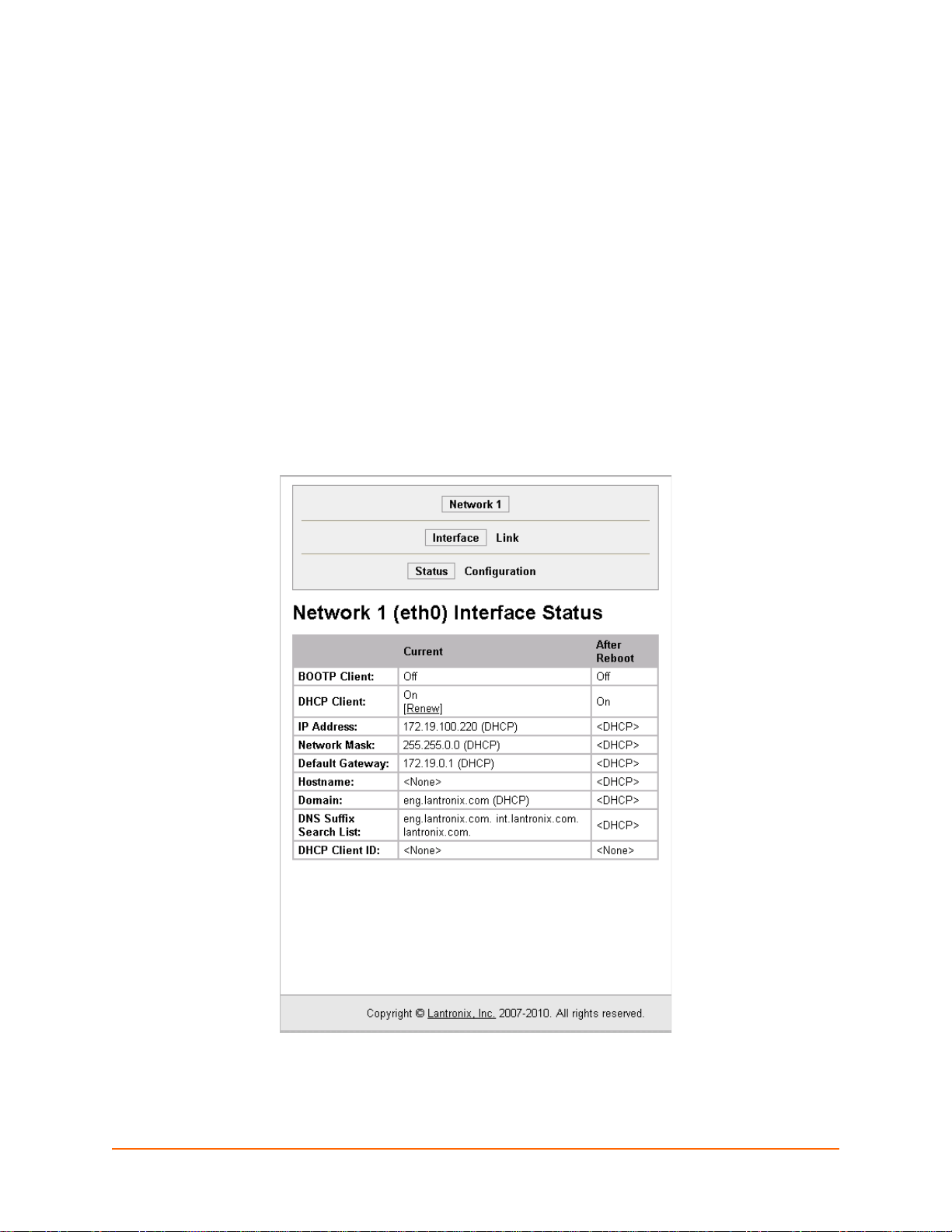
Network 1 Interface Status
To view the Network 1 interface status, click Network on the Main Menu. Figure 5-1 shows the
page that displays. Using this page, you can view the status on your network interfaces.
Figure 5-1 Network 1 (eth0) Interface Status Web Page
XPort AR User Guide 28
Page 29
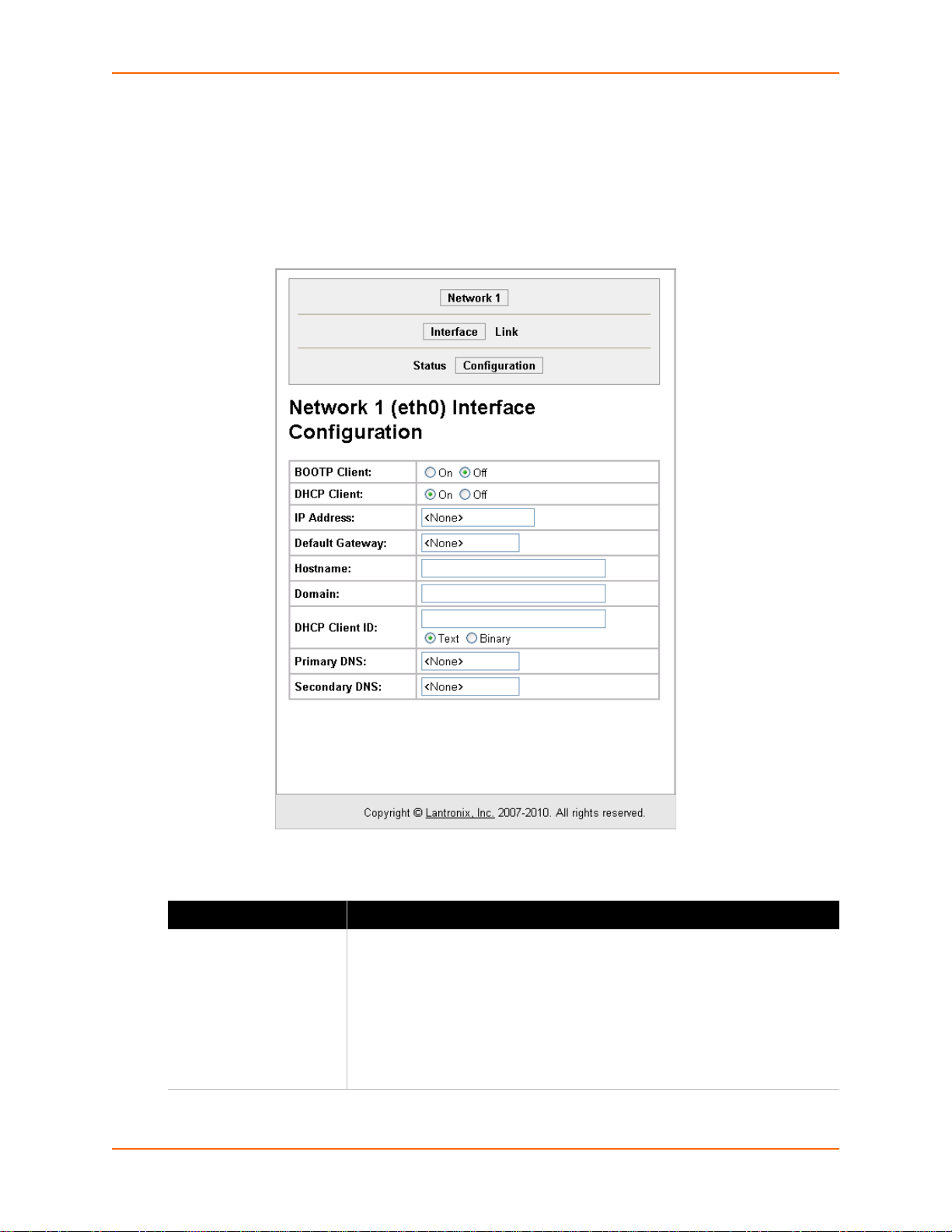
Network 1 Interface Configuration
To configure the Network interface, perform the following steps.
1. Click Network on the Main Menu.
2. Click Network 1 > Interface > Configuration. Figure 5-2 shows the page that displays.
Figure 5-2 Network 1 (eth0) Interface Configuration Web Page
5: Network Settings
3. Enter or modify the fields in Table 5-1.
Table 5-1 Network 1 Interface Configuration Fields
Field Description
BOOTP Client Select On or Off. At boot up the XPort AR will attempt to obtain an IP
address from a BOOTP server.
Notes:
Overrides the configured IP address, network mask, gateway,
hostname, and domain.
When DHCP is On, the system automatically uses DHCP, regardless of
whether BOOTP Client is On.
XPort AR User Guide 29
Page 30

5: Network Settings
Table 5-1 Network 1 Interface Configuration Fields (continued)
Field Description
DHCP Client Select On or Off. At boot up the XPort AR will attempt to lease an IP address
from a DHCP server and maintain the lease at regular intervals.
Note: Overrides BOOTP, the configured IP address, network mask,
gateway, hostname, and domain.
IP Address Enter the XPort AR static IP address. You may enter it alone, in CIDR format,
or with an explicit mask. The IP address is used if BOOTP and DHCP are
both set to Off. Changing this value requires you to reboot the XPort AR.
Note: When DHCP is enabled, the XPort AR tries to obtain an IP address
from DHCP. If it cannot, AutoIP, a server-less method of selecting the IP
address when the DHCP server is unavailable, assigns an address in the
range of 169.254.xxx.xxx.
Default Gateway Enter the IP address of the router for this network. Or clear the field (appears
as <None>). This address is only used for static IP address configuration.
Hostname Enter the XPort AR hostname. It must begin with a letter, continue with a
sequence of letters, numbers, and/or hyphens, and end with a letter or
number.
Domain Enter the domain name.
DHCP Client ID Enter the ID if the DHCP server uses a DHCP ID. The DHCP server lease
table shows IP addresses and MAC addresses for devices. The lease table
shows the Client ID, in hexadecimal notation, instead of the XPort AR MAC
address.
Primary DNS IP address of the primary name server. This entry is required if you choose to
configure a DNS (Domain Name Server).
Secondary DNS IP address of the secondary DNS.
4. Click Submit. Changes to the following settings require a reboot for the changes to take
effect:
BOOTP Client
DHCP Client
IP address
DHCP Client ID
Network 1 Ethernet Link
To display and change settings in the Network 1 Ethernet Link web page, perfor m the following
steps.
XPort AR User Guide 30
Page 31

1. Click Network on the Main Menu.
2. Click Network 1 > Link. Figure 5-3 shows the page that displays.
Figure 5-3 Network 1 (eth0) Ethernet Link Web Page
5: Network Settings
3. Enter or modify the fields in Table 5-2.
Table 5-2 Network 1 (eth0) Ethernet Link Fields
Field Description
Speed Select the Ethernet link speed. Auto is the default.
Duplex Select the Ethernet link duplex mode. Auto is the default.
4. Click Submit.
XPort AR User Guide 31
Page 32

6: Line and Tunnel Settings
This chapter describes how to view and configure lines and tunnels. It contains the following
sections:
Line Settings
Tunnel Settings
Line Settings
You can view statistics and configure the serial interfaces (referred to as lines) by using the Line
web page. When you click Line from the Main Menu, Line 1 fields display. To go to Line 2, click
the Line 2 button.
The XPort AR supports software and hardware flow control on Lines 1 and 2. Line 3 can be
configured for software flow control. Tunnels can only be configur ed on Lines 1 and 2 a nd not Line
3. Line 3 is typically used as a console or ded ic ated co ntrol channe l. PPP is not allowed on Line 3.
The following sub-menus you can use:
Line Statistics—Displays statistics for the two lines. For example, the bytes received and
transmitted, breaks, flow control, parity errors, etc.
Line Configuration—Enables the change of the name, interface, protocol, baud rates, and
parity, etc.
Line Command Mode—Enables the types of modes, wait time, serial strings, signon
message, etc.
Line Statistics
To display the line statistics, perform the following steps.
XPort AR User Guide 32
Page 33

6: Line and Tunnel Settings
1. Click Line on the Main Menu. Figure 6-1 shows the page that displays.
Figure 6-1 Line 1 Statistics Web Page
Line Configuration
To configure a line, perform the following steps.
XPort AR User Guide 33
Page 34

6: Line and Tunnel Settings
1. Click Line > Line 1 > Configuration. Line 2 has the same fields as Line 1. Figure 6-2 shows
the page that displays.
Figure 6-2 Line 1 Configuration Web Page
2. Enter or modify the fields in Table 6-1.
Table 6-1 Line 1 Configuration Fields
Field Description
Name Enter a name for the line.
State Indicates whether the current line is enabled. To change the status, select
Enabled or Disabled from the drop-down menu.
Protocol Select the protocol from the drop-down menu. The default is Tunnel.
Note: All protocols work in Connect and Accept Mode except the LPD or
Tunnel protocol option which is supported only in Accept Mode.
Baud Rate Select the baud rate from the drop-down menu. The default is 9600.
Parity Select the parity from the drop-down menu. The default is None.
Data Bits Select the number of data bits from the drop-down menu. The default is 8.
Stop Bits Select the number of stop bits from the drop-down menu. The default is 1.
XPort AR User Guide 34
Page 35

6: Line and Tunnel Settings
Table 6-1 Line 1 Configuration Fields (continued)
Field Description
Flow Control Select the flow control from the drop-down menu. The default is None.
Xon Char Specify the character to use to start the flow of data when Flow Control is set
to Software. Prefix a decimal character with \ or a hexadecimal character with
0x, or provide a single printable character. The default Xon char is 0x11.
Xoff Char Specify the character to use to stop the flow of data when Flow Control is set
to Software. Prefix a decimal character with \ or a hexadecimal character with
0x, or provide a single printable character. The default Xoff char is 0x13.
Threshold The driver will also forward received characters after Threshold bytes have
been received.
3. Click Submit.
Line Command Mode
To configure the Command Mode, perform the following steps.
1. Click Line > Line 1 > Command Mode. Figure 6-3 shows the page that displays.
Figure 6-3 Line 1 Command Mode Web Page
XPort AR User Guide 35
Page 36

6: Line and Tunnel Settings
2. Enter or modify the fields in Table 6-2.
Table 6-2 Line 1 Command Mode Fields
Field Description
Mode Select the method of enabling Command Mode or choose to disable
Command Mode.
Always—Immediately enables Command Mode for the serial line.
U s e Serial String—Enables Command Mode when the serial string is
read on the serial line during boot time.
Use CP Group—Enables Command Mode based on the status of a CP
Group.
Us e bo th Seria l String and CP Group—Enables Command Mode
when both the serial string and the value of the CP Group are matched.
Disabled—Turns off Command Mode.
Wait Time Enter the wait time for the serial string during boot-up in milliseconds.
Serial String Enter the serial string characters. Select a string type.
Text—String of bytes that must be read on the Serial Line during boot
time to enable Command Mode. It may contain a time element in x
milliseconds, in the format {x}, to specify a required delay.
Binary—String of characters representing byte values where each
hexadecimal byte value starts with \0x and each decimal byte value
starts with backslash (\).
Echo Serial String Select Yes to enable echoing of the serial string at boot-up.
CP Group Enter the CP Group name and value after selecting Use CP Group in the
Signon Message Enter the boot-up signon message. Select a string type.
3. Click Submit.
Tunnel Settings
Tunneling allows serial devices to communicate over a network, without “being aware” of the
devices which establish the network connection be tween them. When a ny character is tran smitted
to the serial port, it gets copied to the network connection.Tunneling parameters are configured
using the Web Manager or CLI Tunnel Menu (refer to the XPort AR Command Reference for the
full list of commands).
Mode field. When the value matches the current value of the group,
Command Mode is enabled on the Serial Line.
Text—String of bytes sent on the serial line during boot time.
Binary—One or more byte values separated by commas. Each byte
value may be decimal or hexadecimal. Start hexadecimal values with
0x.
Note: This string gets output on the serial port at boot, regardless of
whether command mode is enabled or not.
XPort AR User Guide 36
Page 37

6: Line and Tunnel Settings
The XPort AR supports two connections simultaneously per serial port. One of the connections is
Connect Mode and the other connection is Accept Mode. The connections on one serial port are
separate from those on the other serial port.
Connect Mode—Makes an active connection. The receiving node on the network must listen
for the Connect Mode connection. Connect Mode is disabled by default.
Accept Mode—Listens for a connection. A node on the network initiates the connection.
Accept Mode is enabled by default.
Disconnect Mode—Defines how an open connection stop s the forwarding of data. The specific
parameters to stop the connection are configurable. Once a defined event occurs, the XPor t
AR disconnects Accept Mode and Connect Mode connections on that port.
You can view statistics and configure two tunnels by using the Tunnel web page. When you click
Tunnel from the Main Menu, Tunnel 1 fields display. To go to Tunnel 2, click the Tunnel 2 button.
There are six sub-menus that you can use as follows:
Statistics—Displays statistics for the two lines. For example, comp leted accepts, completed
connects, disconnects, dropped accepts, dropped connects, etc.
Serial Settings—Configures buffer size and DTR.
Connect Mode—Controls how a tunnel behaves when a connection attempt originates
locally.
Accept Mo de—Controls how a tunnel behaves wh en a connection attempt originat es from the
network.
Disconnect Mode—Relates to the disconnect of a tunnel.
Packing Mode—Sends packed data that is queued in larger chunks instead of sending it
immediately after being read on the serial line.
Modem Emulation—Initiates and accepts tunnel connections using the AT commands.
Tunnel Statistics
The XPort AR logs tunneling statistics. The Dropped statistic shows connections ended by the
remote location. The Disconnects statistic shows connections ended by the XPort AR.
To display the tunnel statistics, perform the following steps.
XPort AR User Guide 37
Page 38

6: Line and Tunnel Settings
1. Click Tunnel on the Main Menu. Figure 6-4 shows the page that displays.
Figure 6-4 Tunnel 1 Statistics Web Page
Serial Settings
Serial line settings are configurable for both serial line 1 and serial lin e 2. Configure the b uffer size
to change the maximum amount of data the serial port stores. For any a ctive connection, the XPort
AR sends the data in the buffer.
The modem control signal DTR on the Line may be continually asserted or asserted only while
either an Accept Mode tunnel or a Connect Mode tunnel is connected.
To configure the serial settings, perform the following steps.
XPort AR User Guide 38
Page 39

6: Line and Tunnel Settings
1. Click Tunnel > Tunnel 1 > Serial Settings. Figure 6-5 shows the page that displays.
Figure 6-5 Tunnel 1 Serial Settings Web Page
2. View or modify the fields in Table 6-3.
Table 6-3 Tunnel 1 Serial Settings Fields
Fields Description
Line Settings Display only field. Current serial settings for the line.
Protocol Display only field. The protocol being used for the tunnel.
Buffer Size Enter the buffer size used for the tunneling of serial data received. Requires
reboot to take effect.
DTR Select when to assert DTR.
Unasserted
Asserted while connected—Asserted whenever a connect or an
accept mode tunnel connection is active.
Continuously asserted—Asserted regardless of the status of a tunnel
connection. Status of a tunnel connection does not affect the DTR
signal.
XPort AR User Guide 39
Page 40

6: Line and Tunnel Settings
3. Click Submit.
Packing Mode
Packing Mode takes data from the serial port, packs it together, and sends over the network.
Packing can be configured based on threshold (size in bytes, timeout (milliseconds), or a single
character.
Size is set by modifying the threshold field. When the number of bytes reaches the threshold, a
packet is sent immediately.
The timeout field is used to force a packet to be sent after a maximum time. The packet is sent
even if the threshold value is not reached.
When Send Character is configured, a single printable character or control character read on the
Serial Line forces the packet to be sent immediately. There is an optional trailing character
parameter which can be specified. It can be a single printable character or a co ntrol character.
To configure the tunnel packing mode, perform the following steps.
1. Click Tunnel > Tunnel 1 > Packing Mode. Figure 6-6 shows the page that displays.
Figure 6-6 Tunnel 1 Packing Mode Web Page
XPort AR User Guide 40
Page 41

6: Line and Tunnel Settings
Packing Mode using Timeout
To configure Packing Mode using Timeout, click Timeout. Figure 6-7 shows the page that
displays.
Figure 6-7 Tunnel 1 Packing Mode (Timeout)
1. Enter or modify the fields in Table 6-4.
Table 6-4 Tunnel Packing Mode (Timeout) Fields
Field Description
Threshold Send the queued data when the number of queued bytes reaches the
threshold value.
Timeout Enter a time, in milliseconds, for the XPort AR to send the queued data after
the first character was received.
2. Click Submit.
XPort AR User Guide 41
Page 42

6: Line and Tunnel Settings
Packing Mode using Send Character
To configure Packing Mode using Send Character, click Send Character. Figure 6-8 shows the
page that displays.
Figure 6-8 Tunnel 1 Packing Mode (Send Character)
1. Enter or modify the fields in Table 6-5.
Table 6-5 Tunnel Packing Mode (Send Character) Fields
Field Description
Threshold Send the queued data when the number of queued bytes reaches the
threshold value.
Send Character Enter a single character, either a printable character or control character, for
the send character. Upon receiving this character on the serial line, the XPort
AR sends out the queued data.
Trailing Character This is an optional setting. Enter a single character, either a printable
character or control character, for the trailing character. This character is sent
immediately following the send character.
2. Click Submit.
XPort AR User Guide 42
Page 43

6: Line and Tunnel Settings
Accept Mode
In Accept Mode, the XPort AR waits for a connection from the network. The configurable local port
is the port the remote device connects to for this connection. There is no remote port or address.
The default local port is 10001 for serial port 1 and 10002 for serial port 2.
Accept Mode supports the following protocols:
SSH (XPort AR acts as the server). When using SSH, the SSH server host keys and at least
one SSH authorized user must be configured.
SSL
TCP
AES encryption over TCP
Telnet (XPort AR supports IAC codes. It drops the IAC codes when Telnetting and does not
forward them to the serial port).
Accept Mode has the following states:
Disabled (never a connection)
Enabled (always listening for a connection)
Active if it receives any character from the serial port
Active if it receives a specific (configurable) character from the serial port (same start
character as Connect Mode’s start character)
Modem control asserted
Modem emulation
To configure Accept Mode, perform the following steps.
XPort AR User Guide 43
Page 44

6: Line and Tunnel Settings
1. Click Tunnel 1 > Accept Mode. Figure 6-9 shows the page displays.
Figure 6-9 Tunnel 1 Accept Mode Web Page
2. Enter or modify the fields in Table 6-6.
Table 6-6 Tunnel Accept Mode Fields
Field Description
Mode Select the method used to start a tunnel in Accept mode. Choices are:
Disabled—Do not accept an incoming connection.
Always—Accept an incoming connection. (default)
Any Character—Start waiting for an incoming connection when any
character is read on the serial line.
Start Character—Start waiting for an incoming connection when the
start character for the selected tunnel is read on the serial line.
Modem Control Asserted—Start waiting for an incoming connection
as long as the Modem Control pin (DSR) is asserted on the serial line
until a connection is made.
Modem Emulation—Start waiting for an incoming connection when
triggered by modem emulation AT commands. Connect mode must also
be set to Modem Emulation.
XPort AR User Guide 44
Page 45

6: Line and Tunnel Settings
Table 6-6 Tunnel Accept Mode Fields (continued)
Field Description
Local Port Enter the port number for use as the local port. The defaults are port 10001
for Tunnel 1 and port 10002 for Tunnel 2.
Protocol Select the protocol type for use with Accept Mode. The default protocol is
TCP. If you select TCP AES you will need to configure the AES keys.
TCP Keep Alive Enter the time, in seconds, the XPort AR waits during a silent connection
before checking if the currently connected network device is stil l on the
network. If the unit then gets no response after 8 attempts, it drops that
connection.
Flush Serial Data Select Enabled to flush the serial data buffer on a new connection.
Block Serial Data Select On to block, or not tunnel, serial data transmitted to the XPort AR.
Block Network Data Select On to block, or not tunnel, network data transmitted to the XPort AR.
Password Enter a password that clients must send to the XPort AR within 30 seconds
from opening a network connection to enable data transmission.
The password can have up to 31 characters and must contain only
alphanumeric characters and punctuation. When set, the password sent to
the XPort AR must be terminated with one of the following: (a) 0x0A (LF), (b)
0x00, (c) 0x0D 0x0A (CR LF), or (d) 0x0D 0x00.
Email on Connect Select whether the XPort AR sends an email when a connection is made.
Select None if you do not want to send an email. Otherwise, select the Email
profile to use for sending.
Email on Disconnect Select whether the XPort AR sends an email when a connection is closed.
Select None if you do not want to send an email. Otherwise, select the Email
profile to use for sending.
CP Output Enter a CP Group whose value should change when a connection is
established and dropped.
Con nection valu e—Specifies the value to set the CP Group to when a
connection is established.
Disconnection value—Specifies the value to set the CP Group to
when the connection is closed.
3. Click Submit.
Connect Mode
Connect Mode defines how the XPort AR makes an outgoing connection. For Connect Mode to
function, it must be enabled, have a remote station configured, and a remote port configured (TCP
or UDP). When enabled, Connect Mode is always on.
Enter the remote host address station as an IP address or DNS name. The XPort AR will not make
a connection unless it can resolve the address. For DNS names, after 4 hours of an active
connection, the XPort AR will re-evaluate the address. If it is
close the connection.
maps to a different address, it will
Connect Mode supports the following protocols:
TCP
AES encryption over TCP and UDP
XPort AR User Guide 45
Page 46

6: Line and Tunnel Settings
SSH (the XPort AR is the SSH client)
SSL
UDP (available only in Connect Mode because it is a connectionless protocol).
Telnet
Note: The Local Port in Connect Mode is independent of the port configured in Accept
Mode.
Connect Mode has six modes used to initiate and maintain a connection:
Disable (no connection)
Always (always makes a connection)
Any Character (active if it sees any character from the serial port)
Start Character (active if it sees a specific (configurable) character from the serial port)
Modem Contro l Asserted (started when the modem control pin is asserted on the serial line)
Modem Emulation (started by an ATD command)
To configure Tunnel 1 Connect Mode, perform the following steps.
XPort AR User Guide 46
Page 47

6: Line and Tunnel Settings
1. Select Tunnel 1 > Connect Mode. Figure 6-10 shows the page that displays.
Figure 6-10 Tunnel 1 Connect Mode Page
2. Enter or modify the fields in Table 6-7.
Table 6-7 Tunnel 1 Connect Mode Fields
Field Description
Mode Select the method to be used to attempt a connection to a remote host or
device. Choices are:
Always—A connection is attempted until one is made. If the connection
gets disconnected, the XPort AR retries until it makes a connection.
(default)
Disable—An outgoing connection is never attempted.
Any Character—A connection is attempted when any character is read
on the serial line.
Start Character—A connection is attempted when the start character
for the selected tunnel is read on the serial line.
XPort AR User Guide 47
Page 48

6: Line and Tunnel Settings
Table 6-7 Tunnel 1 Connect Mode Fields (continued)
Field Description
Modem Control Asserted—A connection is attempted as long as the
Modem Control (DSR) is asserted, until a connection is made.
Configure the Modem Control Asserted setting (for DSR or DTR) to start
a connection when the signal is asserted. The XPort AR will try to make
a connection indefinitely. If the connection closes, it will not make
another connection unless the signal is asserted again.
Modem Emulation—A connection is attempted when triggered by
modem emulation AT commands.
Note: For the “any character” or “specific character” modes, the XPort AR
waits and retries the connection. Once it makes a connection and
disconnects, it cannot reconnect until it sees “any character” or the “start
character” again (depending on the configured setting).
Local Port Enter the port for use as the local port. A random port is selected by default.
Once you have configured a number, click the Random link in the Current
Configuration to switch back to random.
Host Click <None> in the Host field to configure the Host parameters and enter the
following fields:
Address—Enter the remote Host Address as an IP address or DNS
name. It designates the address of the remote host to connect to.
Port—Enter the port for use as the Host Port. It designates the port on
the remote host to connect to.
Protocol—Select the protocol type. Your choices are: SSH, SSL, TCP,
TCP AES, Telnet, UDP, and UDP AES. The default protocol is TCP.
When TCP is enabled, probes are sent to the other end of the
connection to ensure that the connection is still valid. Default is 45000
milliseconds. Enter zero to disable and blank the value to restore the
default.
The following fields are available:
- For SSH, the SSH Username field displays. Enter a username.
This is required. The XPort AR is the client and the SSH client
username must be configured on the remote SSH server before
using the XPort AR.
Note: If security is a concern, it is highly recommended that SSH be used.
When using SSH, both the SSH Server Host Keys and SSH Server
Authorized Users must be configured.
- For SSL, there are no additional fields.
- For TCP AES, enter the TCP Keep Alive value in milliseconds, and
AES Encrypt/Decrypt Key. The AES Encrypt/Decrypt key field
displays the presence of key. When setting AES encryption, both
the encrypt key and the decrypt key must be specified. Both of the
keys may be set to the same value.
- For Telnet, enter the TCP Keep Alive value in milliseconds.
- For UDP, there are no additional fields.
- For UDP AES, enter the encrypt/decrypt keys.
Note: For UDP, the XPort AR accepts packets from any device on the
network. It send packets to the last device that sent it packets.
XPort AR User Guide 48
Page 49

6: Line and Tunnel Settings
Table 6-7 Tunnel 1 Connect Mode Fields (continued)
Field Description
Reconnect Timer Enter the reconnect time in milliseconds. The XPort AR attempts to reconnect
after the specified amount of time when a connection fails or when exiting an
established connection. This behavior depends upon the Disconnect Mode.
Notes:
When you configure Tunnel - Connect Mode, you can specify a
number of milliseconds to attempt to reconnect after a dropped
connection has occurred. The default is 1500 milliseconds.
The Reconnect Timer only applies if a Disconnect Mode is configured.
With a Disconnect Mode set, the device server maintains a connection
until the disconnect mode condition is met (at which time the device
server closes the connection). If the tunnel is dropped due to conditions
beyond the device server, the device server attempts to re-establish a
failed connection when the specified reconnect interval reaches its limit.
Any network-side disconnect is considered an error and a reconnect is
attempted without regard to the Connect Mode settings. Simultaneous
Connect Mode connections require some Disconnect Mode
configurations or the connections will never terminate. See Disconnect
Mode on page 50 for more information about the parameters.
If Disconnect Mode is disabled and the network connection is dropped,
then the re-establishment of a tunnel connection is governed by the
configured Connect Mode settings.
Flush Serial Data Select whether to flush the serial line when a connection is made. Choices
are:
Enabled—Flush the serial line when a connection is made.
Disabled—Do not flush the serial line. This is the default.
Block Serial Data Select On to block (not tunnel) serial data transmitted to the XPort AR.
Block Network Data Select On to block (not tunnel) network data transmitted to the XPort AR.
Email on Connect Select whether the XPort AR sends an email when a connection is made.
Select None if you do not want to send an email. Otherwise, select the Email
profile to use.
Email on Disconnect Select whether the XPort AR sends an email when a connection is closed.
Select None if you do not want to send an email. Otherwise, select the Email
profile to use.
CP Output Enter a CP Group whose value should change when a connection is
established and when it is dropped.
Con nection valu e—Specifies the value to set the CP Group to when a
connection is established.
Disconnection value—Specifies the value to set the CP Group to
when the connection is closed.
3. Click Submit.
XPort AR User Guide 49
Page 50

6: Line and Tunnel Settings
Disconnect Mode
Disconnect Mode ends Accept Mode and Connect Mode connections. It runs in the background of
an active connection to determine when to disconnect. When disconnecting, the XPort AR shuts
down connections gracefully. The following settings end a connection:
Stop character received.
Timeout pe riod elapsed and no activity. Both Accept Mode and Connect Mode must be idle for
a specified time frame.
Modem control inactive setting.
Note: To clear data out of the serial buffers upon a disconnect, enable “Flush Serial
Data”.
To configure Disconnect Mode, perform the following steps.
1. Click Tunnel 1 > Disconnect Mode. Figure 6-11 shows the page that displays.
Figure 6-11 Tunnel 1 Disconnect Mode Web Page
XPort AR User Guide 50
Page 51

6: Line and Tunnel Settings
2. Enter or modify the fields in Table 6-8.
Table 6-8 Tunnel Disconnect Mode Fields
Field Description
Stop Character Enter the stop character in ASCII, hexadecimal, or decimal
notation. Select <None> to disable.
Modem Control Select Enabled to disconnect when the modem control pin is
not asserted on the serial line.
Timeout Enter a time, in milliseconds, for the XPort AR to disconnect on
a timeout. The value 0 (zero) disables the idle timeout.
Flush Serial Data Select Enabled to flush the serial data buffer on a
disconnection.
3. Click Submit.
Modem Emulation
The XPort AR supports Modem Emulation mode for devices that send out modem signals. There
are two different modes supported:
Command Mode—Sends verbal response codes.
Data Mode—Information transferred in gets transferred out.
It is possible to change the default settings for verbose response codes, echo commands, and
quiet mode, by using Command Mode commands. The current settings can be overridden;
however on reboot, the settings return to the programmed settings.
Configure the connect string as required. The connect string appends to the communication
packet when the modem connects to a remote location. It is possible to append additional text to
the connect message.
Command Mode
The Modem Emulation Command Mode supports the standard AT command set. For a list of
available commands from the serial or Telnet login, enter AT?. Use ATDT, ATD, and ATDP to
establish a connection. All of these commands behave like a modem. Fo r commands that are valid
but not applicable to the XPort AR, an “OK” message is sent (but the command is silently ignored).
The XPort AR attempts to make a Command Mode connection as per the IP/DNS/port numbers
defined in Connect Mode. It is possible to override the remote address, as well as the remote port
number.
Table 6-9 lists and describes the available commands.
Table 6-9 Modem Emulation Commands and Descriptions
Command Description
+++ Switches to Command Mode if entered from serial port during connection.
AT? Help.
ATDT<Address Info> Establishes the TCP connection to socket (<ipaddress>:<port>).
ATDP<Address Info> See ATDT.
XPort AR User Guide 51
Page 52

6: Line and Tunnel Settings
Table 6-9 Modem Emulation Commands and Descriptions (continued)
Command Description
ATD Like ATDT. Dials default Connect Mode remote address and port.
ATD<Address Info> Sets up a TCP connection. A value of 0 begins a command line interface
session.
ATO Switches to data mode if connection still exists. Vice versa to '+++'.
ATEn Switches echo in Command Mode (off - 0, on - 1).
ATH Disconnects the network session.
ATI Shows modem information.
ATQn Quiet mode (0 - enabl e results code, 1 - disable results code.)
ATVn Verbose mode (0 - numeric result codes, 1 - text result codes.)
ATXn Command does nothing and returns OK status.
ATUn Accept unknown commands. (n value of 0 = off. n value of 1 = on.)
AT&V Display current and saved settings.
AT&F Reset settings in NVR to factory defaults.
AT&W Save active settings to NVR.
ATZ Restores the current state from the setup settings.
ATS0=n Accept incoming connection.
N value of 0—Disable
N value of 1—Connect automatically
N value of 2+—Connect with ATA command.
ATA Answer incoming connection (if ATS0 is 2 or greater).
A/ Repeat last valid command.
For commands that can take address information (ATD, ATDT, ATDP), the destination address
can be specified by entering the IP Address, or entering the IP Address and port number. For
example, <ipaddress>:<port>. The port number cannot be entered on its own.
For ATDT and ATDP commands less than 255 characters, the XPort AR replaces the last
segment of the IP address with the configured Connect Mode remote station address. It is po ssible
to use the last two segments also, if they are under 255 characters. For exampl e, if the ad dress is
100.255.15.5, entering “ATDT 16.6” results in 100.255.16.6.
When using ATDT and ATDP, enter 0.0.0.0 to switch to the Command Line Interface (CLI). Once
the CLI is exited by using the CLI exit command, the XPort AR reverts to modem emulation mode.
By default, the +++ characters are not passed through the connection. Turn on this capability
using the modem echo pluses command.
To configure modem emulation, perform the following steps.
XPort AR User Guide 52
Page 53

6: Line and Tunnel Settings
1. Select Tunnel 1 > Modem Emulation. Figure 6-12 shows the page that displays.
Figure 6-12 Tunnel 1 Modem Emulation Web Page
2. Enter or modify the fields in Table 6-10.
Table 6-10 Tunnel Modem Emulation Fields
Field Description
Echo Pluses Select Enable to echo +++ when entering modem Command Mode.
Echo Commands Select Enable to echo the modem commands to the console.
Verbose Response Select Enable to send modem response codes out on the serial line.
Response Type Select the type of response code: Text or Numeric.
Error Unknown
Commands
Select whether an ERROR or OK response is sent in reply to unrecognized
AT commands. Choices are:
Enabled—ERROR is returned for unrecognized AT commands.
Disabled—OK is returned for unrecognized AT commands. Default is
Disabled.
Incoming Connection Select whe the r Incoming Connection requests will be disabled, answered
automatically, or answered manually. Default is Disabled.
XPort AR User Guide 53
Page 54

6: Line and Tunnel Settings
Table 6-10 Tunnel Modem Emulation Fields (continued)
Field Description
Connect String Enter the connect string. This modem initialization string prepares the
modem for communications. It is a customized string sent with the
“CONNECT” modem response code.
Display Remote IP Selects whether the incoming RING sent on the Serial Line is followed by the
IP address of the caller. Default is Disabled.
3. Click Submit.
XPort AR User Guide 54
Page 55

7: Terminal and Host Settings
This chapter describes how to view and configure terminals and hosts. It contains the following
sections:
Terminal Settings
Host Configuration
Terminal Settings
You can configure a terminal on a serial line or on the network by using the Terminal web page.
When you click Terminal from the Main Menu, Line 1 fields display. To go to the network or line 2,
click the Network or Line 2 button.
Network Terminal Configuration
To configure menu features applicable to CLI access via the network, perform the following steps.
1. Click Terminal > Network. Figure 7-1 shows the page tha t disp la ys.
Figure 7-1 Terminal on Network Configuration Web Page
XPort AR User Guide 55
Page 56

7: Terminal and Host Settings
2. Enter or modify the fields in Table 7-1.
Table 7-1 Terminal on Network Configuration Fields
Field Description
Terminal Type Enter text to describe the type of terminal. The text will be sent to a host via
interpret as command (IAC).
Note: IAC is a method to send commands over the network such as send
break or start echoing.
Login Connect Menu Select the interface to display when the user logs in. Choices are:
Enabled —Shows the Login Connect Menu.
Disabled—Shows the CLI
Exit Connect Menu Select whether to display a choice for the user to exit the Login Connect
Menu and reach the CLI. Choices are:
Enabled—Allows the user to exit to the CLI.
Disabled—No exit to the CLI.
Echo Applies only to Connect Mode Telnet connections, not to Accept Mode. Only
disable Echo if your terminal echoes, in which case you will see double of
each character typed.
3. Click Submit.
Line Terminal Configuration
To configure a line to support an attached terminal, perform the following steps.
XPort AR User Guide 56
Page 57

7: Terminal and Host Settings
1. Click Terminal on the Main Menu and then select the line that is connected to the terminal
you want to configure. The default is Line 1. Figure 7-2 shows the page that displays.
Figure 7-2 Terminal on Line 1 Configuration Web Page
2. Enter or modify the fields in Table 7-2.
Table 7-2 Terminal on Line 1 Configuration Fields
Field Description
Terminal Type Enter text to describe the type of terminal. The text will be sent to a host via
interpret as command (IAC).
Note: IAC is a method to send commands over the network such as send
break or start echoing.
Login Connect Menu Select the interface to display when the user logs in. Choices are:
Enabled —Shows the Login Connect Menu.
Disabled—Shows the CLI
Exit Connect Menu Select whether to display a choice for the user to exit the Login Connect
Menu and reach the CLI. Choices are:
Enabled—A choice allows the user to exit to the CLI.
Disabled—There is no exit to the CLI.
XPort AR User Guide 57
Page 58

Table 7-2 Terminal on Line 1 Configuration Fields (continued)
Field Description
Send Break Enter a Send Break control character, e.g., <control> Y, or blank to disable.
Break Duration Enter how long the break should last in milliseconds.
Echo Applies only to Connect Mode Telnet connections, not to Accept Mode. Only
3. Click Submit.
Host Configuration
You can configure a remote host by using the Host web pag e. To configure a remote host, perform
the following steps.
1. Click Host > Host 1. Figure 7-3 shows the page that displays.
7: Terminal and Host Settings
When the Send Break control character is received from the network on its
way to the serial line, it is not sent to the line; instead, the line output is forced
to be inactive (the break condition).
disable Echo if your terminal echoes, in which case you will see double of
each character typed.
Figure 7-3 Host Configuration Web Page
XPort AR User Guide 58
Page 59

7: Terminal and Host Settings
2. Enter or modify the fields in Table 7-3.
Table 7-3 Host Configuration Fields
Field Description
Name Enter a name for the host. This name appears on the Login Connect Menu.
To leave a host out of the menu, leave this field blank.
Protocol Select the protocol to use to connect to the host. Choices are:
Telnet
SSH
Note: SSH keys must be loaded or created on the SSH page for the SSH
protocol to work.
SSH Username Appears if you selected SSH as the protocol. Enter a username to select a
pre-configured Username/Password/Key (configured on the SSH: Client
Users page), or leave it blank to be prompted for a username and password
at connect time.
Remote Address Enter an IP address for the host to which the XPort AR will connect.
Remote Port Enter the port on the host to which the XPort AR will connect.
3. Click Submit.
XPort AR User Guide 59
Page 60

8: Configurable Pins Manager
This chapter describes the function and config u ration of configurable pins (CPs) by using the
Configurable Pins Manager (CPM).
This chapter contains the following sections:
Overview
Configurable Pins
CPM Groups
Overview
Each CP is associated with an external hardware pin. CPs can be configured and used as digital
inputs or outputs.
When used as input, device functionality can be triggered based on the state of a CP. For
example, an email can be sent when a CP is asserted to a preconfigured level. When used as an
output, logic levels of the CP can be manipulated when a preconfigured event occurs on the
device server, such as when a tunnel connection is accepted.
CPs are configured and manipulated within a group. Each group is named and is referenced in the
feature that is triggering a CP or being triggered by a CP. Sophisticated use of CPs can be
accommodated by adding more than one CP into a group.
Default Groups
The XPort AR has several predefined CP groups used to assign a CP to a needed function. For
instance, when working with an RS485 driver that requires a signal to be asserted when in half–
duplex mode, the CP that is driving that signal (chosen by the engineer designing the circuit) is
added to the default group named Line1_RS485_HDpx. The XPort AR asserts the CP at the
correct time via the default group.
Custom Groups
The email, tunneling, and CLI features can interact with CPs. This is accomplished by creating a
custom group and adding CPs of your choice into that group. Once a CP group is created and
populated with one or more CPs, actions can be triggered when the CPs match a specified value.
CPs can be placed in any bit position within a group, allowing for sophisticated use of the available
CPs.
Configurable Pins
The CPM web page is used to experimentally configure the sta te of the CPs. CPs can be changed
to be a digital input or a digital output, and whether it is asserted high or low. Changes made on
this page do not persist through a reboot.
Rules for configuring a CP are as follows. A CP:
Can be in any number of groups.
Can be only in one active group. Two groups with the same CP cannot be enabled at the
same time.
Becomes locked and is not configurable if it is in an enabled group. Disable the group to
change the CP configuration.
XPort AR User Guide 60
Page 61

8: Configurable Pins Manager
When you are ready to permanently configure the CPs, see the CPM Groups web page. See CPM
Groups on page 63.
Change CPs
To change XPort AR CPs, perform the following steps.
1. Click CPM on the menu bar and then CPs at the top of the page. Figure 8-1 shows the page
that displays. Table 8-1 lists and describes the current configuration fields.
Figure 8-1 CPM CPs Page
Table 8-1 CPM CPs Current Configuration Fields and Descriptions
Field Description
CP Indicates the configurable pin number.
Ref Indicates the hardware pin number associated with the CP.
Configured As Shows the current CP configuration. A CP configured as Input is set to read
input. A CP configured as Output drives data out of the XPort AR.
XPort AR User Guide 61
Page 62

8: Configurable Pins Manager
Table 8-1 CPM CPs Current Configuration Fields and Descriptions (continued)
Field Description
Value Shows the current value of the CP.
Groups Indicates the number of groups in which the CP is a member.
Active In Group Shows the group in which the CP is active. A CP can be a member of several
groups. However, it may only be active in one group.
2. Click a CP number (CP column) to display the status of that pin. The status is shown in the CP
Status section of the web page. Table 8-2 lists and describes the fields for the selected CP.
Table 8-2 CPM CPs Status Fields and Descriptions
Fields Description
Name Shows the CP number.
State Shows the current enable state of the CP. On the XPort AR the CP state is
always enabled.
Type Indicates whether the CP is set for input or output.
Value Shows the current value of the CP.
Bit Shows the bit position. CPs are always displayed in bit position zero.
Level Indicates the voltage level of the CP. A plus sign (+) indicates the CP is
asserted (the voltage is high). A minus sign (-) indicates the CP voltage is
low.
I/O Indicates the current sta tus of the pin:
I—Input
O—Output
<blank—Unassigned
Logic Indicates that the CP is inverted by displaying an "I".
Binary Shows the assertion value of the corresponding bit.
CP# Shows the CP number.
Groups Lists the groups in which the CP is a member.
Note: To modify a CP, all groups in which it is a member must be disabled. The changes
to a CP are not saved in FLASH.
XPort AR User Guide 62
Page 63

CPM Groups
The CPM Groups page allows for the adding, removing, and mana ging CP groups. A group, based
on its state, can trigger outside events such as sending email messages. Only an enabled group
can be a trigger.
View CP Group Status
Click the CP group name in the Current Configuration section of the page. Table 8-3 lists and
describes the fields in the groups status section of the page.
Table 8-3 CPM Group Status Fields and Descriptions
Field Description
Name Shows the CP Group name.
State Shows the current state of the CP group. Locked groups are Lantronix
Value Shows the current CP group value.
Bit Displays the 7-bit positions for the CPs in the group.
8: Configurable Pins Manager
default groups and cannot be deleted. Use the button in this field to enable or
disable the group.
Level Indicates the voltage level of the CP. A plus sign (+) indicates the CP bit is
asserted (the voltage is high). A minus sign (-) indicates the CP voltage is
low.
I/O Indicates the current sta tus of the pin:
I—Input
O—Output
<blank>—Unassigned
Logic Indicates the output of the CP. An "I" indicates the CP output is inverted. A
blank field indicates that the CP is not inverted.
Binary Shows the assertion value of the corresponding bit. An “x” means that the bit
is unassigned in the group.
CP# Shows the configurable pin number and its bit position in the CP group.
Add Custom CP Groups
To add a custom XPort AR CP group, perform the following step s.
XPort AR User Guide 63
Page 64

8: Configurable Pins Manager
1. Click CPM on the menu bar and then Groups at the top of the page. Figure 8-2 shows the
page that displays. Table 8-4 lists and describes the fields in the Current Con figuration section
of the page.
Figure 8-2 CPM Groups Page
Table 8-4 CPM Groups Current Configuration Fields and Descriptions
Fields Description
Group Name Shows the CP group name.
State Indicates whether the group is enabled or disabled.
CP Info Shows the number of CPs in the group.
2. Enter a group name in the Create Group text box and click Submit.
3. Add CPs with the Add button. Be sure to specify:
CP # .
Bit position.
Input or output.
Assertion level. Check the Assert Low box to specify inverted assertion.
XPort AR User Guide 64
Page 65

8: Configurable Pins Manager
Remove Custom CP Groups
To remove a customer CP group, perform the following steps.
1. Click on the group name that you want to remove. The name is in the Group Name column.
2. Click the red “x” that appears next to the name in the Group Status table.
3. Click OK to confirm the deletion.
Remove CPs from CP Groups
To remove a CP from a CP group, perform the following steps.
1. Click on the Group in the Group Name column that contains the CP to be removed.
2. Select the CP from the Remove drop-down list at the bottom of the page.
3. Click Remove.
XPort AR User Guide 65
Page 66

9: Services Settings
This chapter describes the available services and how to configure each. It contains the following
sections:
DNS Status and Cache
PPP Configuration
SNMP Configuration
FTP
TFTP
Syslog
HTTP
RSS
DNS St atus and Cache
The primary and secondary domain name system (DNS) addresses come from the active
interface. The static addresses displayed on the Network Interface Configuration web page may
be overridden by DHCP or BOOTP. The DNS web page enables you to view the status and cache.
When a DNS name is resolved using a forward lookup, the results get stored in the DNS cache
temporarily. The XPort AR checks the cache when performing forward lookups. Each item in the
cache eventually times out and gets removed automatica lly after a certain p eriod or you can dele te
it manually.
To view the DNS status and cache, perform the following steps.
XPort AR User Guide 66
Page 67

1. Click DNS on the Main Menu. Figure 9-1 shows the page that displays.
Figure 9-1 DNS Status and Cache Web Page
9: Services Settings
PPP Configuration
The Point-to-Point Protocol (PPP) establishes a direct connection between two nodes. It defines a
method for data link connectivity between devices us ing physical layers (such as serial lines). The
XPort AR supports two types of PPP authentication: Password Authentication Protocol (PAP) and
Challenge Handshake Authentication Protocol (CHAP). Both of these authentication methods
require the configuration of a username and password.
PAP authentication offers a straightforward method for the peer to determine its identity. Upon the
link establishment, the user ID and password are repeatedly sent to the authenticator until it is
acknowledged or the connection is terminated. However, PAP is not a strong authentication
process. There is no protection against trial-and-error attacks. The peer is responsible for the
frequency of the authentication comm un ica tio n att em pts.
CHAP is a more secure method than PAP. It works by sending a challenge message to the
connection requestor. Using a one-way hash function, the requestor responds with its value. If the
value matches the server’s own calculations, authentication is provided. Otherwise, the conn ection
is terminated.
Note: RFC1334 defines both CHAP and PAP.
XPort AR User Guide 67
Page 68

9: Services Settings
The XPort AR also supports authentication scheme of “None” when no authentication is required
during link negotiation.
Since the XPort AR does not support Network Address and Port Translation (NAPT), static routing
table entries must be added to the serial-side and network- side devices (both of which are exter nal
devices).
Use the XPort AR Web Manager or CLI to configure a network link using PPP over a serial line.
Turn off Connect Mode, Accept Mode, and Command mode before enabling PPP. The XPort AR
acts as the server side of the PPP link; it can require authentication and assign an IP address to
the peer. Upon PPP configuration, IP packets are routed between Ethernet and PPP interfaces.
The XPort AR does not perform network address translation (NAT) between the serial-side
network interface and the Ethernet/WLAN network interface. Therefore, to pass packets through
the XPort AR, a static route must be configured on both the PPP Peer device and the remote
device it wishes to communicate with. The static route in the PPP Peer device must use the PPP
Local IP Address as its gateway, and the static route in the remote device must use the Ethernet/
WLAN IP Address of the XPort AR as its gateway.
To configure PPP, perform the following steps.
1. Click PPP on the Main Menu. Figure 9-2 shows the page that displays.
Figure 9-2 PPP Configuration Web Page
XPort AR User Guide 68
Page 69

9: Services Settings
2. Enter or modify the fields in Table 9-1.
Table 9-1 PPP Configuration Fields
Field Description
Local IP Address Enter the IP address assigned to the XPort AR’s PPP interface.
Peer IP Address Enter the IP address assigned to the peer (when reque sted during
negotiation).
Authentication Mode Choose the authentication mode:
None—No authentication is required.
PAP—Password Authentication Protocol.
CHAP—Challenge–Handshake Authentication Protocol.
Username Enter a username if authentication will be used on the PPP interface. The
peer must be configured to use the same username.
Password Enter a password if authentication will be used on the PPP interface. The
peer must be configured to use the same password.
3. Click Submit.
SNMP Configuration
Simple Network Management Protocol (SNMP) is a network management tool that monitors
network devices for conditions that need attention. The Web Manager configured SNMP service
sends traps whenever a request for information that contains an incorrect community name and
does not match an accepted system name for the service gets sent.
To configure SNMP, perform the following steps.
XPort AR User Guide 69
Page 70

1. Click SNMP on the Main Menu. Figure 9-3 shows the page that displays.
Figure 9-3 SNMP Web Page
9: Services Settings
2. Enter or modify the fields in Table 9-2.
Table 9-2 SNMP Fields
Field Description
SNMP Agent Select On to enable SNMP.
Read Community Enter the SNMP read-only community string.
Write Community Enter the SNMP read/write community string.
System Contact Enter the name of the system contact.
System Name Enter the system name.
System Description Enter the system description.
System Location Enter the system location.
Traps Enabled Select On to enable the transmission of the SNMP cold start trap messages.
This trap is generated during system boot.
Primary Trap Dest IP Enter the primary SNMP trap host.
XPort AR User Guide 70
Page 71

FTP
9: Services Settings
Table 9-2 SNMP Fields (continued)
Field Description
Secondary Trap Dest IP Enter the secondary SNMP trap host.
3. Click Submit.
Note: You can delete the read and write communities, and system name by clicking the
[Delete] link in the Current Configuration table.
The FTP web page shows the FTP configuration and statistics about the FTP server. To configure
FTP, perform the following steps.
1. Click FTP on the Main Menu. Figure 9-4 shows the page that disp la ys.
Figure 9-4 FTP Web Page
XPort AR User Guide 71
Page 72

TFTP
9: Services Settings
2. Enter or modify the fields in Table 9-3.
Table 9-3 FTP Fields
Field Description
State Select Enabled to enable the FTP server.
Admin Username Enter the username to use when logging in via FTP.
Admin Password Enter the password to use when logging in via FTP.
In the TFTP web page, you can configure the server, and view the status and statistics. To
configure TFTP server, perform the following steps.
1. Click TFTP on the Main Menu. Figure 9-5 shows the page that displays.
Figure 9-5 TFTP Server Web Page
XPort AR User Guide 72
Page 73

2. Enter or modify the fields in Table 9-4.
Table 9-4 TFTP Server Fields
Syslog
9: Services Settings
Field Description
State Select Enabled to enable the TFTP server.
Allow File Creation Select whether to allow the creation of new files stored on the TFTP server.
Allow Firmware Update Specifies whether or not the TFTP Server is allowed to accept a firmware
update for the device. An attempt to update firmware is recognized based on
the name of the file.
Note: TFTP cannot authenticate the client so the device is open to
malicious updates.
Allow XCR Import Specifies whether or not the TFTP server is allowed to accept an XML
configuration file for update. An attempt to import the configuration is
recognized based on the name of the file.
Note: TFTP cannot authenticate the client so the device is open to
malicious updates.
In the Syslog web page, you can configure settings, and view statistics and status. To configure
the Syslog, perform the following steps.
Note: The Syslog file gets saved to lRAM and gets discarded when the XPort AR
reboots. Saving the Syslog file to a server that supports remote logging ser vices (see RFC
3164) allows the administrator to save the complete Syslog history. The default port is
514.
1. Click Syslog on the Main Menu. Figure 9-6 shows the page that displays.
XPort AR User Guide 73
Page 74

Figure 9-6 Syslog Web Page
9: Services Settings
2. Enter or modify the fields in Table 9-5.
Table 9-5 Syslog Fields
Field Description
State Select to enable or disable the syslog.
Host Enter the IP address of the remote server to which system logs are sent for
storage.
Local Port Enter the number of the local port on the XPort AR from which system logs
are sent.
Remote Port Enter the number of the port on the remote server that supports logging
services. The default is 514.
Severity Log Level From the drop-down box, select the minimum level of system message the
XPort AR should log. This setting applies to all syslog facilities. The dropdown list is in descending order of severity (e.g., Emergency is more severe
than Alert.)
XPort AR User Guide 74
Page 75

HTTP
9: Services Settings
HyperText Transfer Protocol (HTTP) is an application layer standard for Internet documents.
HTTP defines how messages get formatte d an d transmitted. It also defines the actions web
servers and browsers should take in response to different commands. HTTP Authentication
enables the requirement of usernames and passwords for access to the XPort AR device.
The HTTP web page contains the following sub-menus:
Statistics—Viewing statistics such as bytes received and transmitted, bad requests,
authorizations required, etc.
Configuration—Configuring and viewing the current configuration.
Authentication—Configurin g and viewing the authentication.
HTTP Statistics
To view HTTP statistics, perform the followin g step s.
1. Click HTTP > Statistics. Statistics is the default. Figure 9-7 shows the page that displays.
Figure 9-7 HTTP Statistics Web Page
XPort AR User Guide 75
Page 76

9: Services Settings
Note: The HTTP log is a scrolling log, with the last Max Log Entries cached and
viewable. You can change the maximum number of entries that can be viewed on the
HTTP Configuration Web Page.
HTTP Configuration
To configure HTTP, perform the following steps.
1. Click HTTP > Configuration. Figure 9-8 shows the page that displays.
Figure 9-8 HTTP Configuration Web Page
2. Enter or modify the fields in Table 9-6.
XPort AR User Guide 76
Page 77

9: Services Settings
Table 9-6 HTTP Configuration Fields
Field Description
HTTP Server Select On to enable the HTTP server.
HTTP Port Enter the port for the HTTP server to use. The default is 80.
HTTPS Port Enter the port for the HTTPS server to use. The default is 443. The HTTP
server only listens on the HTTPS Port when an SSL certificate is configured.
HTTPS Protocols Select to enable or disable the following protocols:
SSL3—Secure Sockets Layer version 3
TLS1.0—Transport Layer Security version 1.0. TLS 1.0 is the
successor of SSL3 as defined by the IETF.
TLS1.1—Transport Layer Security version 1.1
The protocols are enabled by default.
Note: A server certificate and associated private key needs to be installed
in the SSL configuration section to use HTTPS.
Max Timeout Enter the maximum time for the HTTP server to wait when receiving a
request. This prevents Denial-of-Service (DoS) attacks. The default is 10
seconds.
Max Bytes Enter the maximum number of bytes the HTTP server accepts when
receiving a request. The default is 40 kB (this prevents DoS attacks).
Logging Select On to enable HTTP server logging.
Max Log Entries Sets the maximum number of HTTP server log entries. Only the last Max
Log Entries are cached and viewable.
Log Format Set the log format string for the HTTP server. Follow these Log Format
rules:
%a—Remote IP address (could be a proxy)
%b—Bytes sent excluding headers
%B—Bytes sent excluding headers (0 = '-')
%h—Remote host (same as '%a')
%{h}i—Header contents from request (h = header string)
%m—Request method
%p—Ephemeral local port value used for request
%q—Query string (prepend with '?' or empty '-')
%t—Timestamp HH:MM:SS (same as Apache '%(%H:%M:%S)t' or
'%(%T)t')
%u—Remote user (could be bogus for 401 status)
%U—URL path info
%r—Rirst line of request (same as '%m %U%q <version>')
%s—Return status
3. Click Submit.
XPort AR User Guide 77
Page 78

HTTP Authentication
To configure HTTP authentication, perform the following steps.
1. Click HTTP > Authentication. Figure 9-9 shows the page that displays.
Figure 9-9 HTTP Authentication Web Page
9: Services Settings
2. Enter or modify the fields in Table 9-7.
Table 9-7 HTTP Authentication Fields
Fields Description
URI Enter the Uniform Resource Identifier (URI).
Note: The URI must begin with ‘/’ to refer to the filesystem.
Realm Enter the domain, or realm, used for HTTP. Required with the URI field.
XPort AR User Guide 78
Page 79

Table 9-7 HTTP Authentication Fields (continued)
Fields Description
Auth Type Select the authenti cation type:
None—No authentication is necessary.
Basic—Encodes passwords using Base64.
Digest—Encodes passwords using MD5.
SSL—The page can only be accessed over SSL (no password is
required).
SSL/Basic—The page is accessible only over SSL and encodes
passwords using Base64.
SSL/Digest—The page is accessible only over SSL and encodes
passwords using MD5.
Username Enter the Username used to access the URI.
Note: More than one username per URI is permitted. Click Submit and
enter the next Username.
Password Enter the Password for the Username.
9: Services Settings
RSS
3. Click Submit.
Notes:
You can delete URI and users by clicking the [Delete] link in the Current
Configuration table.
The URI, realm, use rname, and password are user-specified, free-form fields. The
URI must match the directory created on the filesystem.
Really Simple Syndication (RSS) (sometimes referred to as Rich Site Summary) is a method of
sending online content to Web users. Instead of actively searching for XPort AR configuration
changes, RSS enables viewing relevant and new information regarding changes made to the
XPort AR via an RSS publisher. RSS can be stored to the file system cfg_log.txt file.
To configure RSS, perform the following steps.
XPort AR User Guide 79
Page 80

1. Click RSS on the Main Menu. Figure 9-10 shows the page that displays.
Figure 9-10 RSS Web Page
9: Services Settings
2. Enter or modify the fields in Table 9-8.
Table 9-8 RSS Fields
Fields Description
RSS Feed Select On to enable RSS feeds to an RSS publisher.
Persistent Select On to enable the RSS feed to be written to a file (cfg_log.txt) and to be
available across reboots.
Max Entries Sets the maximum number of log entries. Only the last Max Entries are
cached and viewable.
Note: You can view and clear settings in the Current Status table by clicking [View] or
[Clear].
XPort AR User Guide 80
Page 81

10: Security Settings
The XPort AR supports Secure Shell (SSH) and Secure Sockets Layer (SSL). SSH is a network
protocol for securely accessing a remote device. SSH provides a secure, encrypted
communication channel between two hosts over a network. It provides authentication and
message integrity services.
Secure Sockets Layer (SSL) is a protocol that manages data transmissiong security over the
Internet. It uses digital certificates for authentication and cryptography against eavesdropping and
tampering. It provides encryption and message integrity services. SSL is widely used for secure
communication to a web server. SSL uses certificates and private keys.
Note: The XPort AR supports SSLv3 and its successors, TLS1.0 and TLS1.1. An incoming
SSlv2 connection attempt is answered with an SSlv3 response. If the initiator also supports
SSLv3, SSLv3 handles the rest of the connection.
This chapter contains the following sections:
SSH Server Host Keys
SSH Server Authorized Users
SSH Client Known Hosts
SSH Client Users
SSL Certificates
SSL RSA or DSA
SSL Certificates and Private Keys
SSL Utilities
SSL Configuration
SSH Server Host Keys
The SSH Server Host Keys web page opens when you click SSH from the M ain Menu. It has four
sub-menus for viewing and changing SSH server host keys, SSH server authorized keys, SSH
client known hosts, and SSH client users.
Note: SSH keys may be created on another computer and uploaded to the XPort AR. For
example, use the ssh-keygen -b 1024 -t dsa command to create a 1024-bit DSA key pair. SSH
Keys from other programs may be converted to the required XPort AR format. Use Open SSH to
perform the conversion.
To create or upload SSH server host keys, perform the following steps.
XPort AR User Guide 81
Page 82

1. Click SSH on the Main Menu. Figure 10-1 shows the page that displays.
Figure 10-1 SSH Server Host Keys Web Page
10: Security Settings
2. Enter or modify the fields in Table 10-1.
Table 10-1 SSH Server Host Keys Fields
Field Description
Upload Keys
Private Key Enter the path and name of the existing private key you want to upload or use
the Browse button to select the key. Be sure the private key will not be
compromised in transit. This implies the data is uploaded over some kind of
secure private network
Public Key Enter the path and name of the existing public key you want to upload or use
the Browse button to select the key.
Key Type Select a key type to use.
RSA—Use this key with SSH1 and SSH2 protocols.
DSA—Use this key with the SSH2 protocol.
XPort AR User Guide 82
Page 83

10: Security Settings
Table 10-1 SSH Server Host Keys Fields (continued)
Field Description
Create New Keys
Key Type Select a key type to use.
RSA—Use this key with SSH1 and SSH2 protocols.
DSA—Use this key with the SSH2 protocol.
Bit Size Select a bit length for the new key: 512, 768, 1024. Using a larger bit size
takes more time to generate the key. Approximate times are:
2 minutes for a 512 bit RSA Key
5 minutes for a 768 bit RSA Key
15 minutes for a 1024 bit RSA key
10 minutes for a 512 bit DSA key
30 minutes for a 768 bit DSA key
70 minutes for a 1024 bit DSA key
Note: Some SSH clients require RSA host keys to be at least 1024 bits
long.
3. Click Submit.
SSH Server Authorized Users
You can change SSH server settings for Authorized Users which are accounts that enable access
to the XPort AR. For example, these SSH accounts can be used to log into the CLI or open an
SSH connection to a device port. Every account must have a pa ssw or d.
The public keys are optional and only necessary if public key authentication is required. Using
public key authentication allows a connection to be made without a password.
Under Current Configuration, User has a Delete User link, and Public RSA Key and Public DSA
Key have View Key and Delete Keylinks. If you click a Delete link, a message asks whether you
are sure you want to delete this information. Click OK to proceed or Cancel to cancel the
operation.
XPort AR User Guide 83
Page 84

10: Security Settings
To configure the SSH server for authorized users, perform the following steps.
1. Click SSH > Server Authorized Users. Figure 10-2 shows the page that displays.
Figure 10-2 SSH Server Authorized Users Web Page
2. Enter or modify the fields in Table 10-2.
Table 10-2 SSH Server Authorized Users Fields
Field Description
Username Enter the name of the user authorized to access the SSH server.
Password Enter the password associated with the username.
Public RSA Key Enter the path and name of the existing public RSA key you want to use with
this user or use the Browse button to select the key. If authentication is
successful with the key, no password is required.
Public DSA Key Enter the path and name of the existing public DSA key you want to use with
this user or use the Browse button to select the key. If authentication is
successful with the key, no password is required.
3. Click Submit.
XPort AR User Guide 84
Page 85

SSH Client Known Hosts
You can change SSH client settings for known hosts. You do not have to complete the fields on
this page for communication to occur. However, adding inform ation in the fields adds another layer
of security that protects against Man-In-The-Middle (MITM) attacks.
To configure the SSH client for known hosts, perform the following steps.
1. Click SSH > Client Known Hosts. Figure 10-3 shows the page that displa ys.
Figure 10-3 SSH Client Known Hosts Web Page
10: Security Settings
2. Enter or modify the fields in Table 10-3.
Table 10-3 SSH Client Known Hosts Fields
Field Description
Server Enter the name or IP address of a known host. If you enter a server name,
the name should match the name of the server used as the Remote
Address in Connect mode tunneling.
Public RSA Key Enter the path and name of the existing public RSA key you want to use with
this known host or use the Browse button to select the key.
XPort AR User Guide 85
Page 86

Table 10-3 SSH Client Known Hosts Fields (continued)
Field Description
Public DSA Key Enter the path and name of the existing public DSA key you want to use with
3. Click Submit.
Note: You can delete stored settings when the [Delete] link displays in the Current
Configuration table.
SSH Client Users
You can configure SSH client settings for users. SSH client known users are used by all
applications that play the role of an SSH client, specifically tunneling in Connect Mode.
Minimumally, a password or key pair must be configured for a user.
The keys for public key authentication can be created on another device and uploaded to the
XPort AR or automatically generated on the XPort AR. If uploading existing keys, be sure the
private key does not get compromised in transit. Upload the data over a secure private ne two rk. If
you are uploading a key, ensure that it is not password protected.
10: Security Settings
this known host or use the Browse button to select the key.
To configure the SSH client users, perform the following steps.
XPort AR User Guide 86
Page 87

10: Security Settings
1. Click SSH > SSH Client Users. Figure 10-4 shows the page that displays.
Figure 10-4 SSH Client Users Web Page
2. Enter or modify the fields in Table 10-4.
Table 10-4 SSH Client Users Fields
Field Description
Username Enter the name that the XPort AR uses to connect to a SSH server.
Password Enter the password associated with the username.
Remote Command Enter the command that can be executed remotely. Default is shell, which
tells the SSH server to execute a remote shell upon connection. This
command can be changed to anything the remote host can perform.
Private Key Enter the name of the existing private key you want to use with this SSH
client user. You can either enter the path and name of the key, or use the
Browse button to select the key.
Public Key Enter the path and name of the existing public key you want to use with this
SSH client user or use the Browse button to select the key.
XPort AR User Guide 87
Page 88

Table 10-4 SSH Client Users Fields (continued)
Field Description
Key Type Select the key type to be used. Choices are:
RSA—Use this key with the SSH1 and SSH2 protocols.
DSA—Use this key with the SSH2 protocol.
Create New Keys
Username Enter the name of the user associated with the new key.
Key Type Select the key type to be used for the new key. Choices are:
RSA—Use this key with the SSH1 and SSH2 protocols.
DSA—Use this key with the SSH2 protocol.
Bit Size Select the bit length of the new key:
512
768
1024
Using a larger Bit Size takes more time to generate the key. Approximate
times are:
2 minutes for a 512 bit RSA Key
5 minutes for a 768 bit RSA Key
15 minutes for a 1024 bit RSA key
10 minutes for a 512 bit DSA key
30 minutes for a 768 bit DSA key
70 minutes for a 1024 bit DSA key
Note: Some SSH clients require RSA host keys to be at least 1024 bits
long.
10: Security Settings
3. Click Submit.
Note: You can delete stored settings when the [Delete] link displays in the Current
Configuration table.
SSL Cipher Suites
The SSL standard defines only certain combinations of certificate type, key exchange method,
symmetric encryption, and hash method. Such a combination is called a cipher suite. Table 10-5
lists the supported cipher suites.
Table 10-5 Supported Cipher Suites
Certificate Key Exchange Encryption Hash
DSA DHE 3DES SHA1
RSA RSA 128 bits AES SHA1
RSA RSA Triple DES SHA1
RSA RSA 128 bits RC4 MD5
XPort AR User Guide 88
Page 89

Table 10-5 Supported Cipher Suites (continued)
Certificate Key Exchange Encryption Hash
RSA RSA 128 bits RC4 SHA1
RSA 1024 bits RSA 56 bits RC4 MD5
RSA 1024 bits RSA 56 bits RC4 SHA1
RSA 1024 bits RSA 40 bits RC4 MD5
Whichever side is acting as server decides which cipher suite to use for a connection. It is usually
the strongest common denominator of the cipher suite lists supported by both sides.
SSL Certificates
The goal of a certificate is to authenticate its sender. It is analogous to a paper document that
contains personal identification information and is signed by an authority, for example a notary or
government agency.
The principles of Security Certificate required that in order to sign other certificates, the authority
uses a private key. The published authority certificate contains the matching pub lic key that allows
another to verify the signature but not recreate it.
10: Security Settings
The authority’s certificate can be signed by itself, resulting in a self-signed or trusted-root
certificate, or by another (higher) authority, resulting in an intermediate authority certificate. You
can build up a chain of intermediate authority certificates, and the last certification will always be a
trusted-root certificate.
An authority that signs another certificates is also called a Certificate Authority (CA). The last in
line is then the root-CA. VeriSign is a famous example of such a root-CA. Its certificate is often
built into web browsers to allow verifying the identity of website serv er s, wh ic h ne e d to ha ve
certificates signed by VeriSign or another public CA. Since obtaining a certificate signed by a CA
that is managed by another company can be expensive, it is possible to have your own CA. Tools
exist to generate self-signed CA certificates or to sign other certificates.
A certificate request is a certificate that has not been signed and only contains the identifying
information. Signing it makes it a certificate. A certificate is also used to sign any message
transmitted to the peer to identify the originator and prevent tampering while transported.
When using HTTPS, SSL Tunneling in Accept mode, and/or EAP-TLS, the XPort AR needs a
personal certificate with a matching private key to identify itself and sign its messages. When using
SSL Tunneling in Connect mode and/or EAP-TLS, EAP-TTLS or PEAP, the XPort AR needs the
authority certificate that can authenticate users with which it wishes to communicate.
SSL RSA or DSA
As mentioned above, the certificates contain a public key. Different key exchange methods require
different public keys and thus different styles of certificate. The XPort AR supports key exchange
methods that require a RSA-style certificate and key exchange methods that require a DSA-style
certificate. If only one of these certificates is stored in the XPort AR, only those key exchange
methods that can work with that style certificate are enabled. RSA is sufficient in most cases.
XPort AR User Guide 89
Page 90

SSL Certificates and Private Keys
You can obtain a certificate by completing a certificate request and sending it to a certificate
authority that will create a certificate/key combo, usually for a fee. Or generate your own. A few
utilities exist to generate self-signed certificates or sign certificate requests. The XPort AR also has
the ability to generate its own self-signed certificate/key combo.
You can use XML to export the certificate in PEM format, b ut you cannot export the ke y. Hence the
internal certificate generator can only be used for certificates that are to identify that particular
XPort AR.
Certificates and private keys can be stored in several file formats. Best known are PKCS12, DER
and PEM. Certificate and key can be in the same file or in separate files. The key can be encrypted
with a password or not. The XPort AR currently only accepts separate PEM files. The key needs to
be unencrypted.
SSL Utilities
Several utilities exist to convert between the formats as follows:
OpenSSL—Open source set of SSL related command line utilities. It can act as server or
client. It can generate or sign certificate requests. It can convert all kinds of formats.
Executables are available for Linux and Windows. To generate a self-signed RSA certificate/
key combo use the following commands in the order shown:
10: Security Settings
openssl req –x509 –nodes –days 365 –newkey rsa:1024 –keyout
mp_key.pem –out mp_cert.pem
Note: Signing other certificate requests is also possible with OpenSSL. See www.openssl.org or
www.madboa.com/geek/openssl for more information.
Steel Belted Radius—Commercial radius server by Juniper Networks that provides a GUI
administration interface. It also provides a certificate request and self-signed certificate
generator. The self-signed certificate has extension .sbrpvk and is in the PKCS12 format.
OpenSSL can convert this into a PEM format certificate and key by usig the following
commands in the order shown:
openssl pkcs12 -in sbr_certkey.sbrpvk -nodes -out sbr_certkey.pem
The sbr_certkey.pem file contains both certificate and key. If loading the SBR certificate into
XPort AR as an authority, you will need to edit it. Open the file in any plain text editor. Delete
all info before the following:
“----- BEGIN CERTIFICATE-----“
and after
“----- END CERTIFICATE-----“
and save as sbr_cert.pem. SBR accepts trusted-root certificates in the DER format. Again,
OpenSSL can convert any format into DER by using the following commands in the order
shown:
openssl x509 -inform pem -in mp_cert.pem -outform der -out
mp_cert.der
XPort AR User Guide 90
Page 91

Note: With SBR, when the identity information includes special characters such as dashes and
periods, SBR changes the format it uses to store these stri ngs and becomes incompatible with the
current XPort AR release. We will add support for this and other formats in future releases.
Free Radius—L inux open-source Radius server. It is versatile, but complicated to configure.
SSL Configuration
To configure SSL, perform the following steps.
1. Click SSL from the Main Menu. Figure 10-5 shows the page that displays.
10: Security Settings
Figure 10-5 SSL Web Page
XPort AR User Guide 91
Page 92

10: Security Settings
2. Enter or modify the fields in Table 10-6.
Table 10-6 SSL Fields
Field Description
Upload Certificate
New Certificate This certificate identifies the XPort AR to peers. It is used for HTTPS and
SSL Tunneling. Enter the path and name of the certificate you want to
upload, or use the Browse button to select the certificate. RSA or DSA
certificates with 512 to 1024 bit public keys are allowed.
Note: The file format must be PEM. The file must start with “-----BEGIN
CERTIFICATE-----“ and end with “-----END CERTIFICATE-----“. Some
Certificate Authorities add comments before and/or after these lines. Those
need to be deleted before upload.
New Private Key Enter the path and name of the private key you want to upload, or use the
Browse button to select the private key. The key needs to belong to the
certificate entered above.
Note: The format of the file must be PEM. The file must start with “-----
BEGIN RSA PRIVATE KEY-----” and end with “-----END RSA PRIVATE
KEY-----”. Read DSA instead of RSA in case of a DSA key. Some Certificate
Authorities add comments before and/or after these lines. Those need to be
deleted before upload.
Upload Authority Key
Authority One or more authority certificates are needed to verify a peer's identity. It is
used for SSL Tunneling. These certificates do not require a private key.
Enter the path and name of the certificate you want to upload, or use the
Browse button to select the certificate. RSA or DSA certificates with 512 to
1024 bit public keys are allowed.
Note: The format of the file must be PEM. The file must start with “-----
BEGIN CERTIFICATE-----” and end with “-----END CERTIFICATE-----”.
Some Certificate Authorities add comments before and/or after these lines.
Those need to be deleted before upload
Create New Self-Signed Certificate
Country Enter the 2-letter country code to be assigned to the new self-signed
certificate. Examples: US for United States and CA for Canada
State/Province Enter the state or province to be assigned to the new self-signed certificate.
Locality Enter the city or locality to be assigned to the new self-signed certificate.
Organization Enter the organization to be associa ted with the new self-signed certificate.
Example: If your company is called Widgets, and you are setting up a web
server for the Sales department, enter Widgets for the organization.
Organization Unit Enter the organizational unit to be associated with the new self-signed
certificate. Example: If your company is setting up a web server for the Sales
department, enter Sales for your organizational unit.
.
Expires Enter the expiration date, in mm/dd/yyyy format, for the new self-signed
certificate. Example: An expiration date of May 9, 2010 is entered as 05/09/
2010.
XPort AR User Guide 92
Page 93

Table 10-6 SSL Fields (continued)
Field Description
Key Length Select the bit size of the new self-signed certificate. Choices are:
512 bits
768 bits
1024 bits
The larger the bit size, the longer it takes to generate the key. Approximate
times are:
2 minutes for a 512-bit RSA key
5 minutes for a 768-bit RSA key
15 minutes for a 1024-bit RSA key
8 minutes for a 512-bit DSA key
20 minutes for a 768-bit DSA key
60 minutes for a 1024-bit DSA key
Type Select the type of key:
RSA—Public-Key Cryptography algorithm based on large prime
numbers, invented by Rivest Shamir and Adleman. Used for encryption
and signing.
DSA—Digital Signature Algorithm also based on large prime numbers,
but can only be used for signing. Developed by the US government to
avoid the patents on RSA.
10: Security Settings
XPort AR User Guide 93
Page 94

11: Maintenance and Diagnostics Settings
This chapter describes maintenance and diag nostic methods and contains the following sections:
Filesystem
Protocol Stack
IP Address Filter
Query Port
Diagnostics
System
Filesystem
The XPort AR uses a flash filesystem to store files. You can view file diagnostics and/or modify
files. There are two subsections: Statistics and Browse.
The Statistics section of the Filesystem Statistics window shows current statistics and usage
information of the flash file system. In the FileSystem Browser section of the Filesystem Statistics
web page, you can create files and folders, upload files, copy and move files, and use TFTP.
Filesystem Statistics and Actions
To display the filesystem statistics, compact, or format the filesystem, perform the following steps.
XPort AR User Guide 94
Page 95

11: Maintenance and Diagnostics Settings
1. Click Filesystem on the Main Menu. Figure 11-1 shows the page that displays.
Figure 11-1 Filesystem Statistics Web Page
2. Click Compact in the Actions row to compact the files.
Note: The compact should not be needed under normal circumstances as the system
manages this automatically.
3. Back up all files before you perform Step 4, because all user files get erased in that step.
4. Cick Format in the Actions row. The configuration gets retained.
Filesystem Browser
To browse the filesystem, perform the followin g step s.
XPort AR User Guide 95
Page 96

11: Maintenance and Diagnostics Settings
1. Click Filesystem > Browse. Figure 11-2 shows the page that displays.
Figure 11-2 Filesystem Browser Web Page
2. Click a filename to view the contents.
XPort AR User Guide 96
Page 97

11: Maintenance and Diagnostics Settings
3. Click the X next to a filename to delete the file and then you can delete the directory. The
directory has to be empty before you can delete it.
Note: Changes apply to the current directory view. To make changes within other
folders, click the folder or directory and then enter the parameters in the settings listed in
Table 11-1.
Files can be copied or moved by using the fields noted in Table 11-1.
Table 11-1 Filesystem Browser Fields
Field Description
Create
File Enter the name of the file you want to create, and then click Create.
Directory Enter the name of the directory you want to create, and then click Create.
Upload File Enter the path and name of the file you want to upload by means of HTTP(S)
or use the Browse button to select the file, and then click Upload.
Copy File
Source Enter the location where the file you want to copy resides.
Destination Enter the location where you want the file copied. After you specify a source
and destination, click Copy to copy the file.
Move
Source Enter the location where the file you want to move resides.
Destination Enter the location where you want the file moved.
After you specify a source and destination, click Move to move the file.
TFTP
Action Select the action that is to be performed via TFTP:
Get—A TFTP get command will be executed to store a file locally.
Put— A TFTP put command will be executed to send a file on the local file
system to a remote location.
Mode Select a TFTP mode to use. Choices are:
ASCII
Binary
Local File Enter the name of the local fi le.
Remote File Enter the name of the file at the remote location that is to be stored locally
(get) or externally (put).
Host Enter the IP address or name of the host involved in this operation.
Port Enter the number of the port involved in TFTP operations on which the
specified TFTP get or put command will be performed. Click Transfer to
perform the TFTP transfer.
XPort AR User Guide 97
Page 98

Protocol Stack
In the Protocol Stack web page, you can configure TCP, IP, ICMP, and ARP.
TCP
To configure the network protocols, perform the following steps.
1. Click Protocol Stack on the Main Menu. TCP is the default. Figure 11-3 shows the page that
displays.
11: Maintenance and Diagnostics Settings
Figure 11-3 TCP Web Page
2. Enter or modify the fields in Table 11-2.
Table 11-2 TCP Fields
Field Description
Send RSTs Click Enabled to send RSTs or Disabled to stop sending RSTs. TCP
contains six control bits, with one or more defined in each packet. RST is one
of the control bits. The RST bit is responsible for telling the receiving TCP
stack to end a connection immediately.
Caution: Setting the RSTs may pose a security risk.
XPort AR User Guide 98
Page 99

11: Maintenance and Diagnostics Settings
Table 11-2 TCP Fields (continued)
Field Description
Ack Limit Enter a number to limit how many packets get received before an ACK gets
forced. If there is a large amount of data to acknowle dge, an ACK gets
forced. If the sender TCP implementation waits for an ACK before sending
more data even though the window is open, setting the Ack Limit to 1
packet improves performance by forcing immediate acknowledgements.
Send Data The Send Data selection governs when data may be sent into the network.
The Standard implementation waits for an ACK before sending a packet less
than the maximum length. Select Expedited to send data whenever the
window allows it.
3. Click Submit.
IP
To change the IP settings, perform the following steps.
1. Click Protocol Stack > IP. Figure 11-4 shows the page that disp la ys.
Figure 11-4 IP Web Page
XPort AR User Guide 99
Page 100

11: Maintenance and Diagnostics Settings
2. Enter the number of hops a multicast packet can complete before it is terminated as a
Multicast Time to Live.
3. Click Submit.
ICMP
To set the ICMP, perform the following steps.
1. Click Protocol Stack > ICMP. Figure 11-5 shows the page that disp la ys.
Figure 11-5 ICMP Web Page
2. Click Enabled.
3. Click Submit.
XPort AR User Guide 100
 Loading...