

Page 1
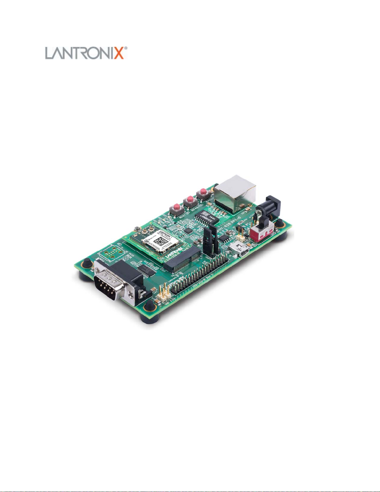
xPico 200 Series Evaluation Kit User Guide
This guide describes how to setup the xPico® 200 series evaluation kit and provides the
information needed to evaluate the included xPico 240 or xPico 250 embedded gateway
modules. The intended audience is the engineers that design the xPico 200 into their
products.
Evaluation Kit Contents
Lantronix® xPico® 200 series allows OEMs to go to market faster with their smart
connected products. It delivers seamless and secure Ethernet, Wi-Fi and/or Bluetooth®
connectivity. Featuring advanced enterprise security, complete Wi-Fi®, network and
Bluetooth stack offload, essential applications for data connectivity and control, preintegration with the MACH10™ platform, the xPico 200 series delivers embedded
gateway capability in an industry-leading compact footprint.
Page 2

The evaluation kit is available in two different variants depending on xPico 200 series
model that is mounted:
1. XPC240300EK - xPico 240 module (Ethernet + Wi-Fi)
2. XPC250300EK - xPico 250 module (Ethernet + Wi-Fi + Bluetooth)
Evaluation Kit Contents:
xPico 200 module (xPico 240 or xPico 250 model) on an edge card
xPico 200 evaluation board with socket for xPico 200 edge card module
5V DC power supply adapter (with international plugs)
2x Antennas with u.fl to R-SMA adapter cable
EvaluationKitDescription
The xPico 200 evaluation kit provides a test platform for the Lantronix xPico 200
gateway module. The evaluation kit uses either 5V power from a USB device port
connector or power supplied 5V barrel connector. The evaluation kit includes all
necessary regulators to power the 3.3V xPico 200 module.
The evaluation kit has the following features:
One DB9M serial port connector with an RS232 transceiver at rates up to 1 Mbps
One RJ45 10/100 Ethernet port with on board PHY and magnetic module
One mini-type B USB device port connector for 5V input power and device port connection to
the xPico 200 module. This port can also be jumpered to act as a Host port for engineering
evaluation. Refer to the xPico 200 Series Embedded Wi-Fi Gateway Integration Guide and
USB.org for proper USB compliant host port implementation.
LEDs for the xPico Ethernet and system status outputs
Access to all logic level IO signals on the xPico 200 via header pins for measurements and
connections to other places
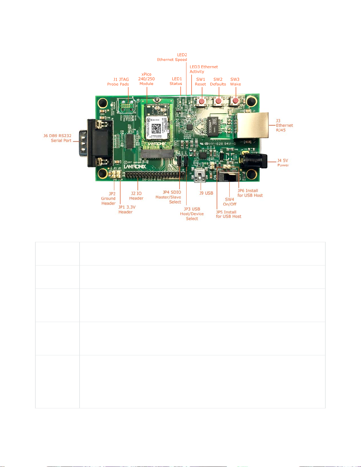
The xPico 240/250 Evaluation Board image shows the xPico 200 evaluation kit with an
attached xPico 200 module, highlighting all of the connectors and configuration
jumpers. The Connectors, Header and Switches table lists each of the connectors and
jumper headers along with their function. Further description and pin assignments are
included in subsequent sections.
Page 3
xPico200EvaluationBoard
Connectors,HeadersandSwitches
Ref Des. Connector/Header Functions
J7 xPico 200 Module Socket
3.3V Power Header
JP1
Test point to monitor the 3.3V regulator output.
Ground Header
JP2
Test point to connect to evaluation board signal ground.
USB Host/Device Select
Install Jumper to pins 1 to 2 for USB Device Mode
JP3
Install Jumper to pins 2 to 3 for USB Host Mode (Host mode also requires
jumper install on JP5, JP6 to provide power out of J9)
Page 4

Ref Des. Connector/Header Functions
SDIO Master/Slave Select
JP4
JP5
JP6
J1
Install Jumper pins 1 to 2 for SDIO Master Mode
Install Jumper pins 2 to 3 for SDIO Slave Mode
USB Host Power Out Jumper
Install to provide power out for USB host mode. Do not install for device mode
(default)
USB Host Power Out Jumper
Install to provide power out for USB host mode. Do not install for device mode
(default)
JTAG Pads
Install JTAG pogo pin header at J1. Use Tag-Connect TC2050-IDC cable probe
and TC2050-ARM2010 adapter for JTAG connections
IO pin header
J2
J3 Ethernet RJ45
J4
J6 DB9 RS232 Serial Port
J7 Edge connector socket for xPico 240/250 module edge card
J9
Header for connection to module power, serial port, and configurable pin
connections.
5V Barrel Connector
Input port for 5V board power
Module USB Port
Defaults to USB device port. Jumper options available to run as a host port.
Page 5

SerialInterface
The evaluation kit has one RS232 port for connection to the xPico 200 internal UART.
Serial port 1 is a DB9M (DTE) connector labeled J6. The null modem cable can be used
to connect J6 directly to a standard PC RS232 serial port.
RS‐232SignalsonJ6SerialInterface
xPico 200 Evaluation Kit
Pin Function Serial Port
TX_232 (Data Out) 3
RX_232 (Data In) 2
CTS_232 (HW Flow Control Input) 8
RTS_232 (HW Flow Control Output) 7
DTR_232 (Modem Control Output)
4
(Populate R56)
DCD_232 (Modem Control Input)
1
(Populate R57)
DB9M
Pin Number
GND (Ground) 5
Note
The evaluation board is configured for RS232 on the UART signals. If attempting to use
the J2 UART TTL header pins instead of the RS232 transceiver, pin 22 of the serial
transceiver (U8) should be tied to ground.
EthernetInterface
The xPico 200 evaluation kit includes one RJ45 connector with on-board magnetics for
connection to the xPico 200 module 10/100Mbps Ethernet interface. Connector J3 is the
Ethernet port.
Page 6

PowerSupply
The evaluation kit provides multiple input Power Options. Included with the kit is a 5V
wall adapter which plugs into barrel connector J4. In addition to powering from the wall
adapter, the evaluation kit can be powered from a standard PC USB Host port by
connecting a USB cable between the PC and J9. If powered via USB, the unit must be
configured for USB device mode (JP3 pins 1 to 2, JP5 out, JP6 out).
PowerOptions
Input Power Option Description
5V Wall Cube Connect 5V wall cube to the J4 barrel connector.
USB (device mode,
power input)
Connect J9 USB power to a PC USB Host Port.
Note: For J9 Note unit must be configured for USB device mode
(JP3 pins 1 to 2, JP5 out, JP6 out.)
LEDs
The xPico evaluation kit includes several LEDs to communicate module, Ethernet activity,
or power status. The LED Signals table lists all LEDs and their functions.
LEDSignals
J7
Pin
6 LED1 Orange
LED Ref
Color LED Function
Design
xPico 200 Status
LED blinks with patterns indicating module status. See the
xPico 200 Series Embedded Wi-Fi Gateway User Guide for
a full description of the status LED blink patterns.
None LED2 Orange
None LED3 Orange
Ethernet Link Status
LED is ON when there is a valid Ethernet link at 100 Mbps
Ethernet Activity
LED blinks when there is activity on the Ethernet port
Page 7

J7
Pin
LED Ref
Color LED Function
Design
None LED4 Blue
3.3V Power LED
LED is ON when evaluation board 3.3V power is up.
J2HeaderPins
The J2 Pin Header table lists the pin functionality of the additional evaluation kit
headers. Included is the J7 connection to the xPico 200 edge module connector.
J2PinHeader
J7 module
pin
N/A 2,4,6 VIN
1,7,18,33,
9,45,51,57,
63,69,75
J2 Header
Pin
1,3,5,33,
35,37,39
Signal Function
Evaluation board
5V power
Evaluation board
Ground
Ground
Secondary
Function
2,4,72,74 34,36,38,40 3V3(M)
Evaluaton board
3.3V power
50 7 CP1 Configurable pin 1
48 9 CP2/INT Configurable pin 2
46 11 CP3 Configurable pin 3 SPI-MISO
Routes to J7 module
pins via R1
USB host mode over-
current flag input
SPI interrupt input
USB host mode port
power enable output
Page 8

J7 module
pin
44 13 CP4 Configurable pin 4 SPI MOSI
58 15 CP5 Configurable pin 5 I2C Data
60 17 CP6 Configurable pin 6 I2C clock
42 19 CP7 Configurable pin 7 SPI Clock
40 21 CP8 Configurable pin 8 SPI Chip Select
9 8 SDCLK SDIO Clock
J2 Header
Pin
Signal Function
Secondary
Function
11 10 SDCMD SDIO Command
13 12 SDIO0 SDIO Data 0
15 14 SDIO1 SDIO Data 1
17 16 SDIO2 SDIO Data 2
19 18 SDIO3 SDIO Data 3
56 20
54 22
I2C Data
2
I2C Clock
2
I2C Bus 2 Data
I2C Bus 2 Clock
16 24 CP9 Configurable pin 9 PWM Output
Page 9

J7 module
pin
J2 Header
Pin
Signal Function
Secondary
Function
62 26 CP10
22 27 TXD1
34 28 RTS1
32 29 RXD1
36 30 CTS1
23, 25, 31,
32
No
connect
Configurable pin
10
UART transmit
data output
UART ready to
send output
UART receive data
input
UART clear to
send input
Reserved-Do not
connect
PWM Output
Please refer to the xPico 200 Series Embedded Wi-Fi Gateway Integration Guide for
evaluation board schematics.
Buttons
J7
Button Signal
SW1 EXT_RESET# 52
SW2 DEFAULTS 23
Module
pin
Button Function
Module Hardware Reset
Button assertion reboots the module
Module Reset to Defaults
Assert for 6 seconds upon boot up to reset the xPico
Page 10

J7
Button Signal
SW3 WAKE 20
Module
pin
200 module to factory defaults
Module Wake Up
Button assertion will wake up the xPico 200 module
from standby or sleep states. Requires the function
to be enabled on the module. See the xPico 200
Series Embedded Wi-Fi Gateway User Guide for
more information on low power states.
Additional Information
Button Function
IntellectualProperty
Lantronix and xPico are registered trademarks of Lantronix, Inc. in the United States and
other countries.
Patented: http://patents.lantronix.com; additional patents pending.
Warranty
For details on the Lantronix warranty policy, please go to our Web site at
https://www.lantronix.com/support/warranty.
Disclaimer
This product has been designed to comply with the limits for a Class B digital device
pursuant to Part 15 of FCC and EN55032 Rules when properly enclosed and grounded.
These limits are designed to provide reasonable protection against radio interference in
a residential installation. This equipment generates, uses, and can radiate radio
frequency energy, and if not installed and used in accordance with this guide, may cause
interference to radio communications. Changes or modifications to this device not
explicitly approved by Lantronix will void the user's authority to operate this device. The
Page 11

information in this guide may change without notice. The manufacturer assumes no
responsibility for any errors that may appear in this guide.
AdditionalDocumentation
Visit the Lantronix web site for the latest documentation and the following additional
documentation.
Document Description
xPico 200
Series User
Guide
xPico 200
Series
Integration
Guide
xPico 200
Series Data
Sheet
xPico 200
Series Product
Brief
Provides information needed to view and configure xPico 200 series
gateway settings through the Lantronix Web Manager, CLI, XML and
WebAPI.
Provides information needed to integrate the xPico 200 series gateway into
customer-printed circuit boards. This includes instructions for connecting
various module pin function groups, and general module placement and
mounting.
Provides detailed technical and compliance specifications about the xPico
200 series gateway.
Provides a quick reference to xPico 200 technical specifications.
CAD Files
FAQ
The Platform PCB Package contains reference board pdf and STEP
mechanical drawings, xPico 200 module pdf and STEP mechanical drawings,
reference board pdf and OrCAD schematics, reference board bill of
materials, reference board Mentor PADS artwork and gerber files, and the
xPico 200 Module Mentor PADS symbol.
Provides a searchable library of Frequently Asked Questions (FAQs) and
articles.
Page 12

For regular updates to Lantronix documentation and to receive product change
notifications, register at the Lantronix homepage.
TechnicalSupport
Lantronix Technical Support offers many resources to support our customers and
products. For instance, ask a question, find firmware downloads, access the FTP site and
search through tutorials, FAQs, bulletins, warranty information, extended support
services, and product documentation.
To contact technical support or sales, look up your local office. When you report a
problem, please provide the following information:
Your name, company name, address, and phone number
Lantronix product and model number
Lantronix MAC address or serial number
Firmware version and current configuration
Description of the problem
Status of the unit when the problem occurred (please try to include information on user and
network activity at the time of the problem).
RevisionHistory
Date Revision Comments
November 2017 A Initial document (firmware 1.6.0.0R58)
https://docs.lantronix.com/products/xpico‐200/evk/ 12‐6‐17
 Loading...