

Page 1
WiSpan Ethernet Bridge
User Guide
1630 W. Diehl Rd.
Naperville, Illinois 60563
+1 630 245-1445, +1 630 245-1717 FAX
www.gridconnect.com
Part Number 900-488
Revision A April 2007
Page 2

Copyright and Trademark
© 2007 Lantronix. All rights reserved. No part of the contents of this book may be
transmitted or reproduced in any form or by any means without the written permission of
Lantronix. Printed in the United States of America.
WiSpan, with its patent-pending technology, is a trademark of Lantronix.
Ethernet is a trademark of XEROX Corporation. UNIX is a registered trademark of The
Open Group. Windows 95, Windows 98, Windows 2000, Windows NT, and Windows XP
are trademarks of Microsoft Corp. Netscape is a trademark of Netscape Communications
Corporation.
Contacts
Lantronix Corporate Headquarters
15353 Barranca Parkway
Irvine, CA 92618, USA
Phone: 949-453-3990
Fax: 949-453-3995
Technical Support
Online: www.lantronix.com/support
Sales Offices
For a current list of our domestic and international sales offices, go to the Lantronix web
site at www.lantronix.com/about/contact
Revisions
Date Rev. Comments
04/07 A
Initial Release
WiSpan User Guide 2
Page 3

Contents
List of Tables __________________________________________________________ 5
List of Figures _________________________________________________________ 5
1: Using This Guide 6
Purpose and Audience___________________________________________________ 6
Chapter Summary ______________________________________________________ 6
Additional Documentation ________________________________________________ 7
2: Introduction 8
Protocol Support _______________________________________________________ 8
Configuration Methods___________________________________________________ 8
3: Hardware 10
4: Quick Start 13
Installing the WiSpan for Configuration _____________________________________ 13
Using Setup Mode for Server and WLAN Configuration ________________________ 14
Serial Connector Pinouts _____________________________________________________ 10
Network Interface ___________________________________________________________ 10
Ethernet Connector Pinouts ___________________________________________________ 11
LEDs_____________________________________________________________________ 11
Using the Setup Port ________________________________________________________ 13
Using the Ethernet Port ______________________________________________________ 14
Server Settings_____________________________________________________________ 15
WLAN Settings _____________________________________________________________ 16
Next Steps ________________________________________________________________ 18
5: Using DeviceInstaller 19
Installing DeviceInstaller _____________________________________________________ 19
Viewing the Current Configuration ______________________________________________ 19
6: Web-Manager Configuration 22
Accessing Web-Manager________________________________________________ 22
Network Configuration __________________________________________________ 23
Automatic IP Address Configuration ____________________________________________ 23
Server Configuration ___________________________________________________ 24
WLAN Configuration ___________________________________________________ 25
Updating Settings______________________________________________________ 28
Applying Defaults ______________________________________________________ 28
7: Advanced Settings and Defaults (Setup Mode) 29
Expert Settings________________________________________________________ 29
TCP Keepalive time in s ______________________________________________________ 29
ARP Cache timeout in s ______________________________________________________ 29
CPU performance___________________________________________________________ 29
HTTP Port Number__________________________________________________________ 30
MTU Size _________________________________________________________________ 30
WiSpan User Guide 3
Page 4

Contents
Enable alternate MAC _______________________________________________________ 30
Ethernet Connection Type ____________________________________________________ 30
Configurable Server Port Number ______________________________________________ 30
Security Settings ______________________________________________________ 30
Disable SNMP _____________________________________________________________ 30
SNMP Community Name _____________________________________________________ 31
Disable Telnet Setup ________________________________________________________ 31
Disable TFTP Firmware Upgrade ______________________________________________ 31
Disable Port 77FE (Hex) _____________________________________________________ 31
Disable Web Server _________________________________________________________ 31
Disable Web Setup__________________________________________________________ 31
Disable ECHO Ports_________________________________________________________ 32
Enable Enhanced Password __________________________________________________ 32
Default Settings _______________________________________________________ 32
WLAN Settings _____________________________________________________________ 32
Expert Settings _____________________________________________________________ 32
Security Settings ___________________________________________________________ 33
Exit Configuration Mode_________________________________________________ 33
8: Monitor Mode 34
Entering Monitor Mode via the Setup Port ___________________________________ 34
Entering Monitor Mode via the Network Port _________________________________ 34
Monitor Mode Commands _______________________________________________ 35
9: Updating Firmware 37
Obtaining Firmware ____________________________________________________ 37
Reloading Firmware____________________________________________________ 37
Using TFTP: Graphical User Interface______________________________________ 37
Using TFTP: Command Line Interface______________________________________ 38
Network Upgrade ______________________________________________________ 38
Recovering the Firmware Using the Setup port and DeviceInstaller _______________ 38
WLAN Country Setting__________________________________________________ 39
10: Troubleshooting 40
Diagnostic LED States __________________________________________________ 40
Problems and Error Message ____________________________________________ 40
Technical Support _____________________________________________________ 42
A: Technical Specifications 43
Technical Specifications ________________________________________________ 43
B: Compliance 44
Compliance Information _________________________________________________ 44
Regulatory Information__________________________________________________ 45
USA Federal Communications Commission (FCC) Notice ___________________________ 45
Canada – Industry Canada Notice ______________________________________________ 45
Europe – R&TTE Directive 99/5/EC, Wireless Notice _______________________________ 46
Australia & New Zealand – Wireless Notice_______________________________________ 46
C: Warranty 48
WiSpan User Guide 4
Page 5

Contents
List of Tables
Table 3-1. WiSpan Connection LEDs ____________________________________________ 11
Table 3-2. WiSpan Diagnostic Mode ____________________________________________ 12
Table 4-1. Standard IP Network Netmasks Representing Host Bits_____________________ 15
Table 8-1. Monitor Mode Commands ____________________________________________ 35
Table 8-2. Command Response Codes __________________________________________ 36
Table 9-1. Firmware Files _____________________________________________________ 37
Table 10-1. WiSpan Technical Specifications______________________________________ 43
List of Figures
Figure 3-1. Back of the WiSpan ________________________________________________ 10
Figure 3-2. DB9M DTE Serial Connector _________________________________________ 10
Figure 3-3. Front of WiSpan ___________________________________________________ 11
Figure 3-4. RJ45 Ethernet Connector____________________________________________ 11
Figure 4-1. WiSpan Connected for Configuration via the Serial Port ____________________ 13
Figure 4-2. Setup Mode ______________________________________________________ 14
Figure 4-3. Change Setup Menu________________________________________________ 14
Figure 6-1. Web-Manager Home Page___________________________________________ 22
Figure 6-2. Network Settings __________________________________________________ 23
Figure 6-3. Server Settings____________________________________________________ 24
Figure 6-4. WLAN Settings ____________________________________________________ 26
Figure 9-1. TFTP Window_____________________________________________________ 38
WiSpan User Guide 5
Page 6

11::UUssiinnggTThhiissGGuuiidde
e
Purpose and Audience
This guide provides the information needed to configure, use, and update the WiSpan. It
is for network administrators, system integrators, and those responsible for installing and
maintaining the WiSpan.
Chapter Summary
The remaining chapters in this guide include:
Chapter Description
2: Introduction
3: Hardware
4: Quick Start
5: Using DeviceInstaller
6: Web-Manager Configuration
7: Advanced Settings and
Defaults (Setup Mode)
8: Monitor Mode
9: Updating Firmware
10: Troubleshooting
A: Technical Specifications
B: Compliance
C: Warranty
The main features of the WiSpan and the protocols it supports.
The WiSpan's connectors and LEDs.
Physically installing and initially configuring the WiSpan.
Locating the WiSpan and viewing its current configuration settings
using this Lantronix utility.
Using Web-Manager to configure server and WLAN properties.
Configuring expert and security settings in Setup Mode and listing
the unit's default settings.
Accessing and using the command line interface for monitoring the
network and diagnosing problems.
Obtaining the latest firmware and update the WiSpan.
Common problems and error messages and how to contact
Lantronix Technical Support.
WiSpan User Guide 6
Page 7

Additional Documentation
The following guides are available on the product CD and the Lantronix web site
(www.lantronix.com
)
1:Using This Guide
WiSpan Quick Start
DeviceInstaller Online Help
Provides instructions for getting your WiSpan up
and running.
Provides information on using DeviceInstaller to
view current configuration settings.
WiSpan User Guide 7
Page 8

22::IInnttrroodduuccttiioon
The WiSpan is an industrial 802.11 b/g wireless-to-Ethernet bridge allowing
10/100 Ethernet-enabled devices to seamlessly connect and communicate over
802.11 b/g wireless networks. By bridging 10/100 Ethernet to 802.11 b/g, wireless
mobility can be added to Ethernet devices.
The WiSpan Ethernet bridge connects or bridges Ethernet devices to wireless networks
using the IP protocol.
Note: The Ethernet interface can only bridge a single wired device.
Typical applications of the WiSpan include:
Cash registers
POS terminals
Vending machines
Industrial equipment
Security panels
n
Protocol Support
The WiSpan Ethernet bridge uses the TCP/IP protocol stack for network
communications. Other supported protocols include:
ARP, UDP, TCP, ICMP, Telnet, TFTP, AutoIP, HTTP, and SNMP for network
communications and management.
TCP, UDP, and Telnet for connections to the setup port.
TFTP for firmware and web page updates.
IP for addressing, routing, and data block handling over the network.
User Datagram Protocol (UDP) for typical datagram applications in which devices
that support UDP interact with other devices without maintaining a point-to-point
connection.
Configuration Methods
For the unit to operate correctly on a network, it must have:
An IP address
Appropriate settings for network communications to an access point
(Infrastructure Mode) or for peer-to-peer connection (Ad Hoc Mode).
Methods for logging into the WiSpan to set configurable parameters include:
WiSpan User Guide 8
Page 9

2: Introduction
Serial & Telnet Ports: There are two approaches to accessing Setup Mode: make a
Telnet connection to the network port (9999) or connect a terminal (or a PC running a
terminal emulation program) to the unit’s setup (serial) port.
DeviceInstaller: This utility provides a GUI interface for locating the WiSpan on the
network, assigning an IP address, viewing the current configuration, and updating
firmware.
Web-Manager: Once the unit has an IP address, you can configure the WiSpan and its
settings using the WiSpan’s web interface, Web-Manager.
WiSpan User Guide 9
Page 10
33::HHaarrddwwaarre
The WiSpan has one setup (serial) port and one Ethernet port for setup and for
connecting an Ethernet device using a network crossover cable. It has an 802.11 b/g
transceiver that connects to another wireless device or to an Access Point (AP).
Following is a description of the serial and Ethernet connectors.
e
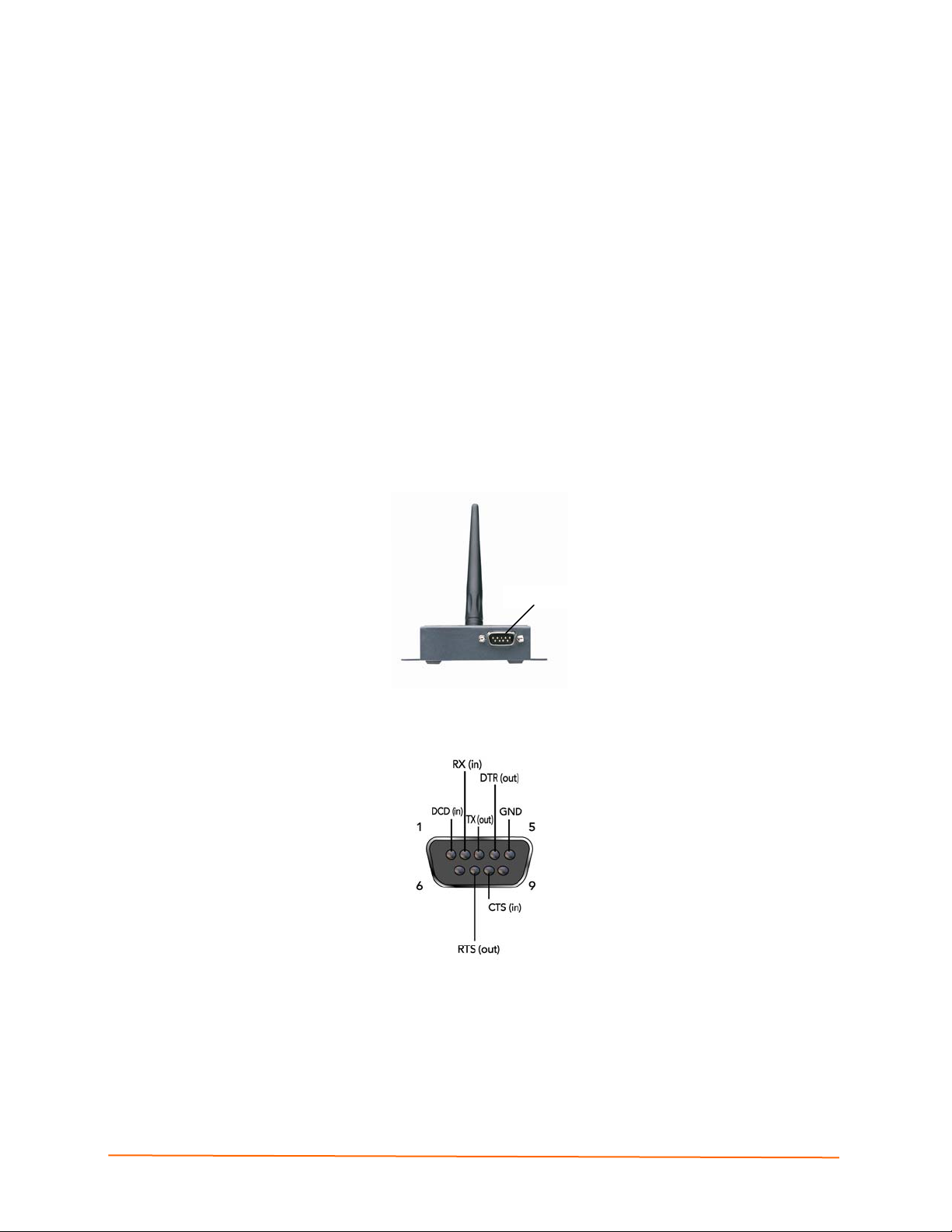
Serial Connector Pinouts
One DB9M DTE setup port provides default settings for RS-232C communications of
9600 baud, 8 bits, no parity, and 1 stop bit (9600, 8, N, 1). The only use of this port is to
configure the unit in Setup Mode.
Figure 3-1. Back of the WiSpan
Setup Port
Figure 3-2. DB9M DTE Serial Connector
Network Interface
The back panel of the WiSpan contains a 9-30 VDC power plug and an RJ45 (10/100)
Ethernet port. You may use the Ethernet port to configure the unit as well as to connect a
network-enabled device to the network using a network crossover cable.
WiSpan User Guide 10
Page 11
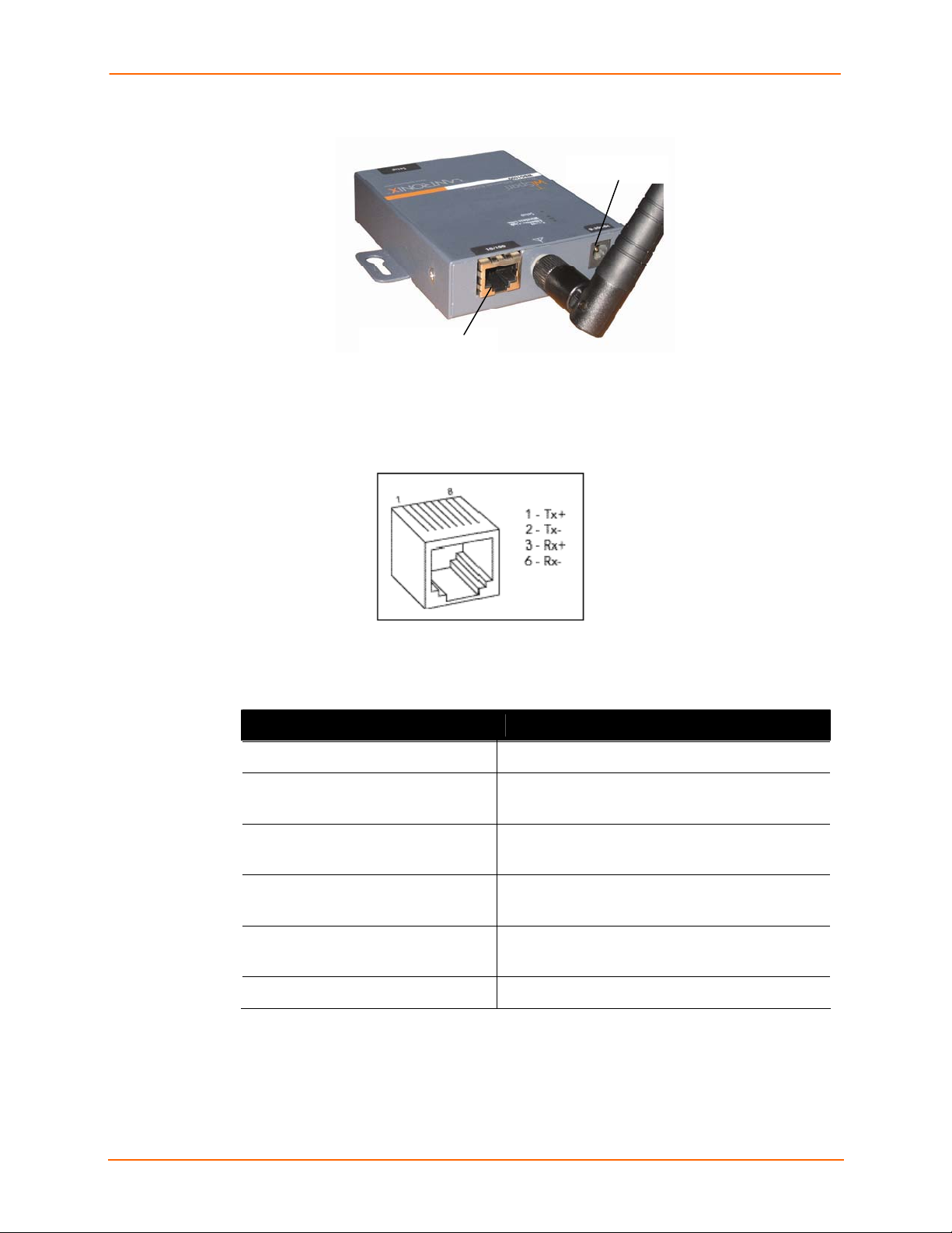
Figure 3-3. Front of WiSpan
RJ45 Ethernet Port
Ethernet Connector Pinouts
Figure 3-4. RJ45 Ethernet Connector
3: Hardware
Power Plug
LEDs
Table 3-1. WiSpan Connection LEDs
LEDs Meaning
Power LED: green, steady ON Power is on.
Wireless Link LED: blinking yellow
Power Management: OFF
Wireless Link LED: OFF
Power Management: OFF
Wireless Link LED: yellow ON
Power Management, ON, OFF
Wireless Link LED: blinking yellow
Power Management: ON
Ethernet Link LED: green, steady on Active network connection.
When you connect to the WiSpan by means of the serial port, the LEDs exhibit the
following pattern, indicating that the unit is in diagnostic mode:
Unit is associating.
Unit is associated.
Steady ON initially and during search
Unit is associated, transmit/receive
WiSpan User Guide 11
Page 12

Table 3-2. WiSpan Diagnostic Mode
LEDs Meaning
Power LED: Green, steady on Power is on
Wireless Link LED: yellow off No active wireless connection.
3: Hardware
Setup (Serial)
Serial LED blinks 4 times, off for 2 seconds and
then repeats.
Note: For information about the WiSpan's diagnostic LEDs, see Diagnostic LED
States on page 40.
WiSpan User Guide 12
Page 13
44::QQuuiicckkSSttaarrt
This chapter describes how to install and configure the WiSpan unit to get it up and
running. You must configure the WLAN settings for the WiSpan to communicate on a
wireless network.
Note: You only need to configure the WiSpan's IP address and other network settings if
you want to discover and configure your WiSpan device from the wired network; these
settings only apply to communication on the Ethernet interface.
t
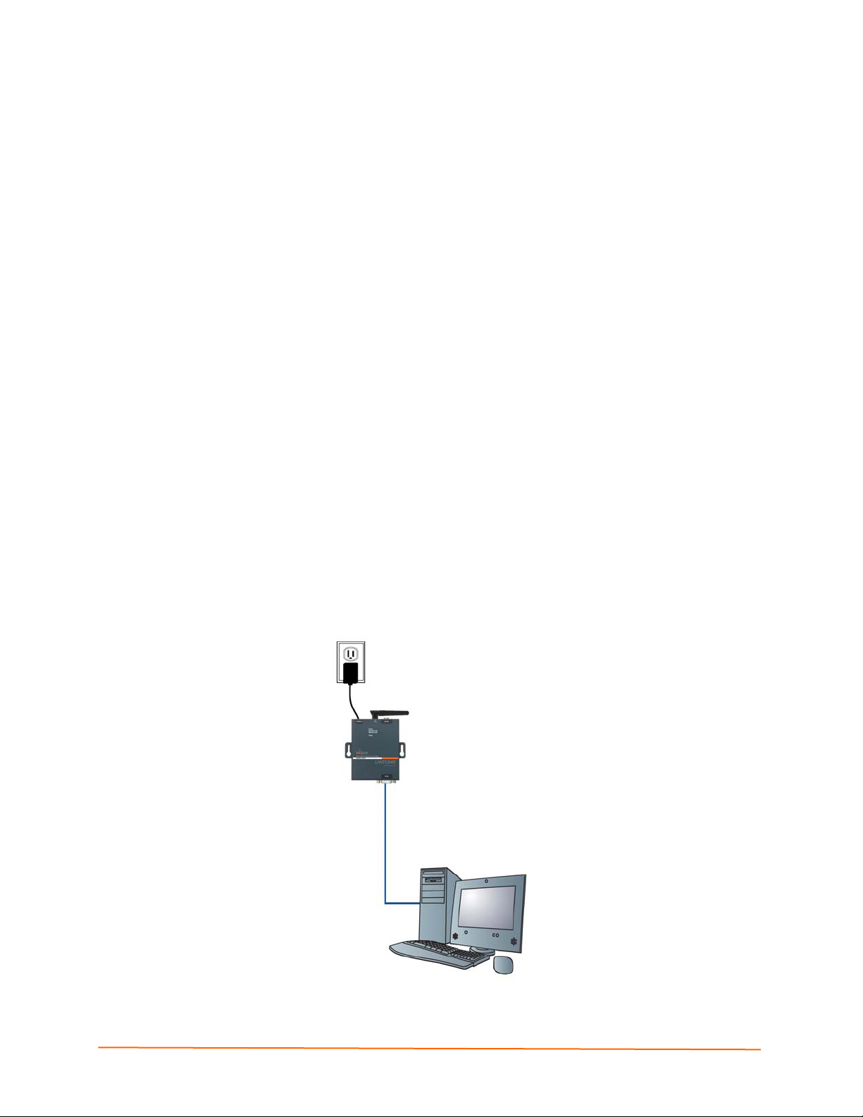
Installing the WiSpan for Configuration
There are two methods for installing the WiSpan so that you can configure it:
Using the Setup Port
To connect to and initially configure the WiSpan using the setup port:
1. Connect one end of the supplied DB9F – DB9F null modem serial cable to the
WiSpan’s setup port.
2. Connect the other end of the DB9 serial cable to a terminal or a PC’s serial COM
port.
3. Continue with Using Setup Mode for Server and WLAN Configuration, below.
Figure 4-1. WiSpan Connected for Configuration via the Serial Port
WiSpan User Guide 13
Page 14

Using the Ethernet Port
To connect to and initially configure the WiSpan using the Ethernet port:
1. If a device is connected to the WiSpan's Ethernet port, disconnect it and connect a
PC for configuring the WiSpan.
2. Set up the PC's Ethernet port for AutoIP or assign a static IP address in the AutoIP
range (169.254.x.x).
3. Use a utility such as DeviceInstaller to locate the WiSpan’s MAC address and IP
address. This utility must use the Lantronix access protocol to query the WiSpan.
(See 5: Using DeviceInstaller.)
4. Use the WiSpan’s Web-Manager (see 6: Web-Manager Configuration) or Telnet to
port 9999 to configure the WiSpan.
Note: Telneting to the WiSpan accesses Setup Mode. The procedure for
using Setup Mode from the Ethernet port is the same as for using the setup
port, described below, starting with step 3.)
5. Disconnect the PC and reconnect the original device to the WiSpan's Ethernet port.
Using Setup Mode for Server and WLAN Configuration
To use Setup Mode for configuration:
4: Quick Start
1. With a connection to the setup port, open a terminal emulation application (e.g.
HyperTerminal) on the PC. The default serial settings are 9600 baud, 8 bits, no
parity, 1 stop bit, and no flow control (9600, 8, N, 1).
2. Enter Setup Mode by simultaneously connecting the power supply and holding down
the x key. Upon connection, information similar to the following displays:
Figure 4-2. Setup Mode
*** Lantronix WiSpan Device Server ***
MAC address 00204A89468C
Software version V6.5.0.2T4 <070221>
Press Enter for Setup Mode
3. Press Enter within 5 seconds to display current settings followed by the Change
Setup menu.
Note: Current values display in parentheses.
Figure 4-3. Change Setup Menu
Note: For initial configuration, only WLAN settings are required. To configure these
settings only, start with WLAN Settings on page 16.
WiSpan User Guide 14
Page 15
4: Quick Start
Server Settings
To configure the Server (WiSpan) settings, select 0 Server from the Change Setup
menu.
The unit’s basic server (network) values display when you select Server (option 0 from
the Change Setup menu). The following sections describe the configurable parameters
within the Server configuration menu.
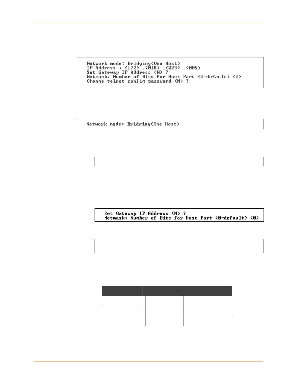
Network Mode: The network mode (Bridging <One Host>).
Set the IP Address: The unit has an automatically assigned IP address. To assign a
static address, enter it manually. The IP address must be set to a unique value in the
network. Enter each octet and press Enter between sections. The current value displays
in parentheses.
IP Address : ( 0) ( 0) ( 0) ( 0) _
Set the Gateway IP Address: The gateway address, or router, allows communication to
other LAN segments. The gateway address should be the IP address of the router
connected to the same LAN segment as the unit. The gateway address must be within
the local network.
The default is N (No), indicating the gateway address has not been set. To set the
gateway address, type Y. At the prompt, enter the gateway address.
Set the Netmask: A netmask defines the number of bits taken from the IP address that
are assigned for the host part.
Netmask: Number of Bits for Host Part (0=default) (0)
_
The unit prompts for the number of host bits to be entered, then calculates the netmask,
which displays in standard decimal-dot notation when the saved parameters display (for
example, 255.255.255.0).
Table 4-1. Standard IP Network Netmasks Representing Host Bits
Network Class Host Bits Netmask
A 24 255.0.0.0
B 16 255.255.0.0
C 8 255.255.255.0
Change Telnet Configuration Password: Change the Telnet configuration password to
prevent unauthorized access to the Change Setup menu and Web-Manager.
WiSpan User Guide 15
Page 16

4: Quick Start
WLAN Settings
To modify WLAN settings, select 4 WLAN from the Change Setup menu and edit the
following fields.
Topology: Select Infrastructure (ESS) mode or AdHoc (IBSS). Infrastructure mode
communicates with Access Points. Ad Hoc mode communicates only with other clients.
Topology 0=Infrastructure, 1=AdHoc (1) ?
Network Name (SSID): Enter the name of the network to which the WiSpan will connect.
Network name (SSID) (LTRX_IBSS) ? _
Ad Hoc Network Creation Channel: When Ad Hoc mode is selected, and the WiSpan
cannot find the specified network, it creates one with that network name by transmitting a
beacon on the selected channel.
Channel (11) ?
You can only select channels allowed in the country for which the WiSpan is designated.
The country displays in the list of current settings when you first access Setup Mode.
Security Suite: The WiSpan features WEP, WPA, and 802.11i-PSK/WPA2-Personal to
secure all wireless communication. WPA and 802.11i-PSK/WPA2-Personal are not
available when the topography is Adhoc. The 802.11i-PSK/WPA2-Personal mode is
compliant with the Robust Secure Network specified by the IEEE standard 802.11i. It
enables the AES-based strong CCMP encryption.
WEP: Authentication 0=open/none, 1=shared (0) ? _
Encryption 0=WEP64, 1=WPE128 (1) ?
Display current key (N) ?
Change key (N) ? Y
Key type 0=hex, 1=passphrase (0) ?
Enter key: **-**-**-**-**
TX Key index (1) ?
Authentication Select whether the encryption keys must match
those of the communication partner before passing through
messages (1 = shared; 2 = open/none).
Encryption Select the length of the encryption key and the security
strength. WEP64 uses a 40 bits/5 bytes key (option 1).
WEP128 uses a 104 bits/13 bytes key (option 2).
Display Current
Key
Change key Select Y (Yes) to modify the currently configured key.
Key type Indicate whether the new key is in hexadecimal or
Enter key Enter the new encryption key. The passphrase input is not
Select Y (Yes) to show the currently configured
key/passphrase
passphrase format.
the same as ASCII input (as used on some products). ASCII
is translated directly into hexadecimal bytes according to the
ASCII table. The WiSpan passphrase is hashed using the
Neesus Datacom algorithm (for WEP64) or MD5 (for
WEP128).
WiSpan User Guide 16
Page 17

4: Quick Start
The passphrase input is safer because it is up to 63 chars
long. ASCII input is a maximum of 5 (WEP64) or 13
(WEP128) characters long and limits the number of key
combinations.
Please refer to the other equipment’s manual to determine
the passphrase input style recommended.
Note: Lantronix recommends using a passphrase of 20
characters or more for maximum security.
TX Key index Select the WEP key used for transmissions from your
access point. Enter a value from 1 to 4.
WPA: The WiSpan firmware allows only Pre-Shared Keys (PSK) for authentication.
Display current key (N) ?
Change key (N) ?
Key type 0=hex, 1=passphrase (1) ?
Enter key: () ?
It is strongly recommended to use a passphrase of 20
chars or more!
Encryption: 0=TKIP, 1=TKIP+WEP (1)
Display current
key
Change key Select Y (Yes) to modify the currently configured key.
Key type Indicate whether the new key is in hexadecimal or passphrase
Enter key
Encryption Set the type to the minimum required security level. The “+” sign
Select Y (Yes) at the prompt to show the currently configured
key/passphrase
format.
Enter the passphrase. The maximum length is 63 characters.
Note: Lantronix recommends using a passphrase of 20
characters or more for maximum security.
indicates that the group (broadcast) encryption method is
different from the pairwise (unicast) encryption (WEP and TKIP).
802.11i-PSK/WPA2-Personal:
Display current key (N) ?
Change key (N) ? Y
Key type 0=hex, 1=passphrase (1) ?
Enter key: () ?
It is strongly recommended to use a passphrase of 20
chars or more!
Encryption: 0=CCMP, 1=CCMP+TKIP, 2=CCMP+WEP, 3=TKIP,
4=TKIP+WEP (4) ?
Display current
key
Change key Select Y (Yes) to modify the currently configured key.
Key type Indicate whether the new key is in hexadecimal or
Enter key Enter the passphrase. The maximum length is 63 characters.
Select Y (Yes) to show the currently configured
key/passphrase.
passphrase format.
WiSpan User Guide 17
Page 18

4: Quick Start
Note: Lantronix recommends using a passphrase of 20
characters or more for maximum security.
Encryption Set the type to the minimum required security level. The “+”
sign indicates that the group (broadcast) encryption method
is different from the pairwise (unicast) encryption. For
example, for CCMP+TKIP, CCMP is the pairwise encryption
and TKIP is the group encryption.
Fixed or Automatic Data Rate
WiSpan enables you to control of the transmission rate. Select 0 to set a fixed data rate
or select 1 to set an automatic data rate. The default is 1 (auto fallback).
TX Data rate: 0=fixed, 1=auto fallback <1> ?
Transmission Data Rate
If the TX Data rate (above) is fixed, the selected data rate is the WiSpan’s fixed
transmission rate. If the TX Data rate is auto fallback, the selected data rate is the
WiSpan’s maximum data rate. Lower data rates allow for larger distances. They may also
be required when communicating with older devices. The default is 11 Mbps.
TX Data rate 0=1, 1=2, 2=5.5, 3=11
4=18, 5=24, 6=36, 7=54 Mbps (0) ? _
Enable Power Management
Select Y (Yes) to enable the software to turn off the radio when expecting not to receive
or transmit soon. This feature reduces the power consumption by up to 170 mA. Enabling
power management increases the response time, because the radio needs to start up
again. The radio synchronizes and checks for incoming messages (every 100 ms).
Note: This option is not available when the topology is AdHoc.
Enable power management (N) ?
Next Steps
1. Upon completing the IP and WLAN settings, select menu option 9 Save and exit.
2. To configure the WiSpan further using the setup port, continue to 7: Advanced
Settings and Defaults (Setup Mode).
WiSpan User Guide 18
Page 19

55::UUssiinnggDDeevviicceeIInnssttaalllleer
You can use DeviceInstaller, a utility on the product CD, to locate a WiSpan and
manually assign it a static IP address, view its current configuration settings, and upgrade
its firmware. DeviceInstaller only works over a wired Ethernet connection to this product.
r
Installing DeviceInstaller
To install the DeviceInstaller:
1. Insert the product CD into your CD-ROM drive.
If the CD does not launch automatically:
a) Click the Start button on the Task Bar and select Run.
b) Enter your CD drive letter, colon, backslash, deviceinstaller.exe (e.g.,
E:\deviceinstaller.exe).
2. Click the DeviceInstaller button. The installation wizard window displays.
3. Respond to the installation wizard prompts. (When prompted to select an installation
type, select Typical.)
4. Once you have installed DeviceInstaller, follow the instructions in DeviceInstaller’s
Online Help to assign the IP address and view the current configuration.
5. To configure the WiSpan further, go to 5: Advanced Settings and Defaults (Setup
Mode) or 6: Web-Manager Configuration.
Viewing the Current Configuration
After locating the WiSpan as described in DeviceInstaller's Online Help, you can view
and change its current configuration.
To view the WiSpan’s configuration settings:
1. In the right window, click the Device Details tab. The current WiSpan configuration
displays:
Name Configurable field. A name to identify the WiSpan. Double-click the
field, type the value, and press Enter to complete. This name is not
visible on other PCs or laptops using DeviceInstaller.
Group Configurable field. A group to categorize the WiSpan. Double-click the
field, type the value, and press Enter to complete. This group name is
not visible on other PCs or laptops using DeviceInstaller.
Comments Configurable field. To enter a comment about the WiSpan, double-click
the field, type the comment, and press Enter. This description or
comment is not visible on other PCs or laptops using DeviceInstaller.
Device Family Non-configurable field. Displays the WiSpan’s device family type as
Wireless.
Type
Non-configurable field. Displays the device type as WiSpan.
WiSpan User Guide 19
Page 20

5: Using DeviceInstaller
ID Non-configurable field. Displays the WiSpan’s ID embedded within the
box.
Hardware
Address
Firmware
Version
Extended
Firmware
Version
Online Status Non-configurable field. Displays the WiSpan’s status as online, offline,
Telnet Enabled
Telnet Port
Web Enabled
WebPort Non-configurable field. Displays the WiSpan’s port for Web-Manager
Maximum Baud
Rate Supported
Firmware
Upgradeable
Non-configurable field. Displays the WiSpan’s hardware (or MAC)
address.
Non-configurable field. Displays the firmware version currently installed
on the WiSpan.
Non-configurable field. Displays the
full version nomenclature of the
firmware installed on the WiSpan.
unreachable (the WiSpan is on a different subnet), or busy (the
WiSpan is currently performing a task).
Non-configurable field. Displays True indicating that you can access
the WiSpan using Telnet.
Non-configurable field. Displays the WiSpan's port for Telnet sessions.
Non-configurable field. Displays True, indicating you can access
WiSpan using Web-Manager.
configuration.
Non-configurable field. Displays the WiSpan’s maximum baud rate.
Non-configurable field. Displays True, indicating the WiSpan’s firmware
is upgradeable as newer versions become available.
IP Address Non-configurable field. Displays the WiSpan’s current IP address. To
change the IP address and related settings, click the Assign IP
Address button and follow the instructions in DeviceInstaller's online
Help.
Number of COB
partitions
supported
Supports
DynamicIP
Subnet Mask
Gateway
Number of Ports
TCP Keepalive
value
Supports
Configurable
Pins
Supports Email
Triggers
Non-configurable field. Displays the number of COB partitions
supported (19).
Non-configurable field. Indicates whether the current IP address was
set automatically.
Non-configurable field. Displays the WiSpan’s current subnet mask.
Non-configurable field. Displays the WiSpan’s current gateway.
Non-configurable field. The number of serial ports.
Displays 1-65s, the WiSpan’s TCP keepalive value.
Non-configurable field. False, indicating configurable pins are not
available on the WiSpan.
Non-configurable field. False, indicating email triggers are not available
on the WiSpan.
WiSpan User Guide 20
Page 21

5: Using DeviceInstaller
Supports AES
Data Stream
Supports 485
Supports 920K
Baudrate
Supports Wired
Ethernet
Supports HTTP
Server
Supports HTTP
Setup
Supports 230K
Baudrate
Supports GPIO
Communication
Non-configurable field. Displays False, indicating the WiSpan does not
support AES encryption.
Non-configurable field. Displays False, indicating the WiSpan does not
support the RS-485 protocol.
Non-configurable field. Displays False, indicating the WiSpan does not
support baud rates up to 920K.
Non-configurable field. Displays True, indicating the WiSpan supports
wired Ethernet.
Non-configurable field. Displays True, indicating the WiSpan supports
HTTP server.
Non-configurable field. Displays True, indicating the WiSpan supports
HTTP setup.
Non-configurable field. Displays False, indicating the WiSpan does not
support a baud rate of 230K.
Non-configurable field. Displays False, indicating the WiSpan does not
support communication via General Purpose Input Output (GPIO).
WiSpan User Guide 21
Page 22

66::WWeebb--MMaannaaggeerrCCoonnffiigguurraattiioon
This chapter describes how to configure the WiSpan using Web-Manager, Lantronix’s
browser-based configuration tool. The unit’s configuration is stored in nonvolatile memory
and is retained without power. The unit performs a reset after the configuration is
changed and stored.
Note: For instructions on setting up the WiSpan for initial configuration using the Ethernet
port, see Using the Ethernet Port on page 14.
n
Accessing Web-Manager
To access Web-Manager through a Web Browser:
1. Open a standard web browser (Netscape Navigator 6.x and later or Internet Explorer
5.5. and later).
2. In the address bar, enter the WiSpan IP address in the following format:
http://xxx.xxx.xxx.xxx
WiSpan unit)
3. Press Enter. The Web-Manager for WiSpan opens in a browser window.
A user and password dialog box displays. By default, no user and password are
configured, so just click OK.
Note: As an alternative, you can access Web-Manager by clicking
DeviceInstaller's Web Configuration tab.
(where xxx.xxx.xxx.xxx is the IP address assigned to the
Figure 6-1. Web-Manager Home Page
The main menu is on the left panel of the Web-Manager window.
WiSpan User Guide 22
Page 23

Network Configuration
Select Network from the main menu to display the unit's network values. The following
sections describe the configurable network parameters.
Note: The automatically assigned IP address and related settings do not display.
Figure 6-2. Network Settings
6: Web-Manager Configuration
Automatic IP Address Configuration
To assign an IP address and its network configuration automatically:
1. Click Network from the main menu.
2. Enter the following:
IP Configuration
AutoIP The WiSpan generates an IP in the 169.254.x.x address
range with a Class B subnet.
To enable this feature: Select the Enable checkbox and
continue with Ethernet Configuration.
To disable this feature: select the Disable checkbox
(default) and continue entering information. Then continue
with Ethernet Configuration.
IP Address If you did not enable AutoIP, enter the static IP address in
standard decimal-dot notation. The IP address must be set to
a unique value in the network.
Subnet Mask A subnet mask defines the number of bits taken from the IP
address that are assigned for the host part.
WiSpan User Guide 23
Page 24

6: Web-Manager Configuration
Default Gateway The gateway address, or router, allows communication to
other LAN segments. The gateway address should be the IP
address of the router connected to the same LAN segment as
the unit. The gateway address must be within the local
network.
Ethernet Configuration
Auto Negotiate With this option, the Ethernet port auto-negotiates the speed
and duplex with the hardware endpoint to which it is
connected. This is the default setting.
If this option is not selected, complete the fields that become
available:
Speed: The speed of data transmission. The default setting is
100 Mbps.
Duplex: The direction of data transmission. The default
setting is Full.
3. Click OK.
4. On the main menu, click Apply Settings.
Server Configuration
Selecting Server from the main menu displays the unit’s server values. The following
sections describe the configurable parameters within the Server configuration menu.
Figure 6-3. Server Settings
To configure the WiSpan’s server settings:
1. Click Server from the main menu.
WiSpan User Guide 24
Page 25

2. Configure or modify the following fields:
Server Configuration
Telnet Password
Enter the password required for Telnet access.
6: Web-Manager Configuration
Retype Password
Re-enter the password required for Telnet access.
Advanced
ARP Cache Timeout When the unit communicates with another device on the
network, it adds an entry into its ARP table. ARP Cache
timeout defines the number of seconds (1-600) before it
refreshes this table.
TCP Keepalive TCP Keepalive time defines how many seconds the unit waits
during an inactive connection before checking its status. If the
unit does not receive a response, it drops that connection.
Enter a value between 1 and 65 seconds. 0 disables
keepalive. The default setting is 45.
Monitor Mode @ Bootup
CPU Performance Mode Select the WiSpan’s performance mode. Higher performance
HTTP Server Port This option allows the configuration of the web server port
Select Disable to disable the entry into Monitor Mode by
means of the yyy or xx1 key sequence at startup. This
command prevents the unit from entering Monitor Mode by
interpreting the stream of characters received during the unit's
initialization at startup.
settings require more energy. Low is 26 Mhz. Regular is 48
Mhz; High is 88 Mhz. The default is Regular.
number. The valid range is 1-65535. The default HTTP server
port number is 80.
Config Server Port The Ethernet wired host attached to the WiSpan may
MTU Size The Maximum Transmission Unit (MTU) is the largest physical
3. When you are finished, click the OK button.
4. On the main menu, click Apply Settings.
WLAN Configuration
Without adequate protection, a wireless LAN is susceptible to access by unauthorized
users.
The WiSpan WLAN Settings menu permits the following actions:
Configuration of the wireless network profile available for activation
Configuration of the wireless network security settings
communicate with other Lantronix CoBos devices on the
wireless network using the Lantronix Configuration Access
Protocol (LCAP). This service is available on server port
number 0x77FE (30718). The LCAP port number is
configurable so that the LCAP service is available on the
wired interface for WiSpan configuration.
packet size a network can transmit for TCP and UDP. Enter
between 512 and 1400 bytes. The default setting is 1400
bytes.
WiSpan User Guide 25
Page 26

6: Web-Manager Configuration
Configuration of advanced settings such as radio power management
Note: For information about country-specific settings, see WLAN
Country Setting on page 39.
To configure the WiSpan’s WLAN settings:
1. Select WLAN from the main menu to open the WLAN Settings window.
Figure 6-4. WLAN Settings
Wireless Network Configuration
Network Name Enter the name of the wireless network (SSID). The WiSpan
connects to this wireless network.
Network Type Select Infrastructure or Ad Hoc. The default is AdHoc.
Channel
Configurable only when Network Type is Ad Hoc. Select the
radio channel for the Ad Hoc network from the drop-down
menu. The default value is 11.
Wireless Network Security
Security The WiSpan features WEP, WPA, and 802.11i-PSK/WPA2-
Personal to secure all wireless communication. If the topology
WiSpan User Guide 26
Page 27

WEP Options
Authentication
6: Web-Manager Configuration
is Ad Hoc, only WEP is available. By default, wireless security
is disabled on the WiSpan.
Select an authentication scheme (Open/None or Shared)
from the drop-down menu.
Encryption
Key Type Select the key type (Hex or Passphrase).
Key & Retype Key
TX Key
Select the encryption type (64 bits or 128 bits for WEP) from
the pull down menu. 64 bits is the default encryption for WEP.
Enter the Encryption Key in hexadecimal value if the key
type is Hex. Enter the key as a string if the key type is
Passphrase. Passphrase input is not the same as ASCII
input.
Note: Lantronix recommends using a passphrase of 20
characters or more for maximum security.
Select the key to use for transmission.
WPA Options
Authentication Select Pre-Shared Keys from the drop-down menu.
Encryption
Key Type Select the key type (Hex or Passphrase).
Key & Retype Key
Select the encryption type from the drop-down menu. TKIP is
the default encryption for WPA.
Enter the Encryption Key in hexadecimal value if the key
type is Hex. Enter the key as a string if the key type is
Passphrase. Passphrase input is not the same as ASCII
input.
Note: Lantronix recommends using a passphrase of 20
characters or more for maximum security.
802.11i/WPA2-Personal Options
Authentication Select Pre-Shared Keys from the drop-down list.
Encryption
Key Type Select the key type (Hex or Passphrase).
Key and Retype Key
Select the encryption type from the drop-down list. CCMP is
the default encryption for WPA.
Enter the Encryption Key in hexadecimal value if the key
type is Hex. Enter the key as a string if the key type is
Passphrase. Passphrase input is not the same as ASCII
input. A passphrase of more than 20 characters is
recommended. Spaces and punctuation characters are
permitted.
Advanced Settings
TX Data Rate WiSpan permits the control of the transmission data rate. Click
the Auto check box to allow the WiSpan to automatically set
the data rate (or leave it unchecked to set the transmission
rate manually). The default rate is 11 Mbps.
WiSpan User Guide 27
Page 28

6: Web-Manager Configuration
If you select Auto, choose the maximum data rate from the
drop-down menu.
If you do not select the Auto check box, select the fixed data
rate (in Mbps) from the drop-down menu.
Note: You cannot select the maximum data rate when the
WiSpan automatically sets the data rate. The WiSpan
supports the following additional rates: 18 Mbps, 24 Mbps, 36
Mbps, and 54 Mbps.
Radio Power
Management
2. When you are finished, click the OK button.
3. On the main menu, click Apply Settings.
Updating Settings
1. If you have not already done so, click the Apply Settings button from the main menu
to save and apply the configuration changes.
Applying Defaults
1. Click the Apply Defaults button to reset the unit’s settings to the factory defaults,
except for the WLAN settings. For a complete list of the default settings, see Default
Settings on page 32.
Power management reduces the overall power consumption
of the WiSpan unit. Selecting Enable increases the response
time.
WiSpan User Guide 28
Page 29

77::AAddvvaanncceeddSSeettttiinnggssaannddDDeeffaauullttss((SSeettuup
p
MMooddee)
)
After performing the initial configuration, you may enter expert and security
settings.
Expert Settings
To configure the Expert settings, select 5 Expert from the Change Setup menu.
Caution: Only an expert should change these parameters. You must
definitely know the consequences the changes may have.
Note: Current values display in parentheses.
TCP Keepalive time in s
Defines how many seconds the unit waits during a silent connection before checking
whether the currently connected network device is still on the network. If the unit does not
receive a response, it drops that connection.
ARP Cache timeout in s
When the unit communicates with another device on the network, it adds an entry into its
ARP table. ARP Cache timeout defines the number of seconds (1-600) the unit waits
before timing out this table.
TCP Keepalive time in s (1s – 65s; 0s=disable): (45)?
_
ARP Cache timeout in s (1s – 65s; 0s=disable): (600)?
_
CPU performance
Select the WiSpan’s performance mode. Higher performance settings require more
energy. Low is 26 Mhz, Regular is 48 Mhz, and High is 88 Mhz. The default setting is
Regular.
CPU performance (0=Regular, 1=Low, 2=High): (0) ? _)?
Disable Monitor Mode @ bootup
Disables entry into Monitor Mode by means of the yyy or xx1 key sequence at startup.
This command prevents the unit from entering Monitor Mode by interpreting the stream of
characters received during the WiSpan's initialization at startup. The default is N (No).
Disable Monitor Mode @ bootup (N) ? _
WiSpan User Guide 29
Page 30

7: Advanced Settings and Defaults (Setup Mode)
HTTP Port Number
This option enables configuration of the web server port number. The valid range is
1-65535. The default HTTP server port number is 80.
HTTP Port Number : (80) ? _
MTU Size
The Maximum Transmission Unit (MTU) is the largest physical packet size a network can
transmit for TCP and UDP. Enter between 512 and 1400 bytes. The default is 1400
bytes.
MTU Size: (1400) ? _
Enable alternate MAC
If necessary, enable the alternate MAC address (if specified in the OEM setup record).
Enable alternate MAC (N) ? _
Ethernet Connection Type
The WiSpan allows you to configure the Ethernet speed and duplex manually.
Enter 0 for auto-negotiation (default). To select the speed and duplex, enter one of the
following: 2 (10 Mbit/half duplex), 3 (10 Mbit/full duplex), 4 (100 Mbit/half duplex), or
5 (100 Mbit/full duplex).
Configurable Server Port Number
The device attached to the WiSpan may communicate with other CoBos devices on the
wireless network using the Lantronix Configuration Access Protocol (LCAP). This service
is available on server port number 0x77FE (30718) and is configurable so that the LCAP
service is available on the wired interface for WiSpan configuration.
Security Settings
Note: Current values display in parentheses.
You can only use a Telnet or serial connection to change Security settings.
Note: Lantronix recommends setting security over the dedicated network or over
the serial setup. Parameters set over the network (Telnet 9999), may allow
someone else to capture these settings.
Ethernet connection type: (0) ? _
Config Server Port Number: (30718) ? _
Caution: Disabling both Telnet setup and Port 77FE prevents users from
accessing the setup menu from the network.
Disable SNMP
If required for security purposes, disable SNMP on the WiSpan unit.
WiBox2100E User Guide 30
Page 31

7: Advanced Settings and Defaults (Setup Mode)
Disable SNMP (N) ? _
SNMP Community Name
The SNMP Community name is a required field for NMS to read or write to a device.
Enter a string of 1 to 13 characters. The default entry is public.
SNMP Community Name (public): _
Disable Telnet Setup
Caution: Disabling both Telnet setup and Port 77FE prevents users from
accessing the setup menu from the network.
This setting defaults to the N (No) option. The Y (Yes) option disables access to Setup
Mode by Telnet (port 9999). It only allows access locally by means of the web pages and
the setup port of the unit.
Disable Telnet Setup (N) ? _
Disable TFTP Firmware Upgrade
This setting defaults to the N (No) option. The Y (Yes) option disables TFTP for network
firmware upgrades.
Disable TFTP Firmware Update (N) : _
Disable Port 77FE (Hex)
Caution: Disabling both Telnet setup and Port 77FE and Web Setup prevents
users from accessing the setup from the network.
Web-Manager and custom programs use Port 77FE to configure the unit remotely. If
required, disable this capability for security purposes.
Select the N (No) option (default) to enable remote configuration by web pages, Telnet,
or serial configuration.
Select the Y (Yes) option to disable remote configuration and web sites.
Note: The Y (Yes) option disables many of the GUI tools for configuring the unit,
including the embedded Web-Manager tool.
Disable Port 77FEh (N) ? _
Disable Web Server
The Y (Yes) option disables the web server. This setting defaults to the N (No) option.
Disabling the web server also disables the web setup.
Disable Web Server (N) ? _
Disable Web Setup
The Y (Yes) option disables configuration by means of the Web-Manager (but the web
server remains active for custom web pages). This setting defaults to the N (No) option.
Disable Web Setup (N) ? _
WiBox2100E User Guide 31
Page 32

Disable ECHO Ports
This setting controls whether the setup port echoes characters it receives.
Enable Enhanced Password
This setting defaults to the N (No) option, which permits a 4-character password to
protect Setup Mode by means of Telnet and web pages.
Select Y (Yes) to allow an extended security password of 16-characters for protecting
Telnet access.
Default Settings
Select 7 Default Settings from the Change Setup menu to reset the unit’s Security and
Expert settings to the factory default settings.
The server configuration settings for IP address and WLAN remain unchanged. Following
are all default settings.
7: Advanced Settings and Defaults (Setup Mode)
Disable ECHO ports (Y) ? _
Enable Enhanced Password (Y) ? _
WLAN Settings
Enable WLAN
Topology
Network Name
Channel
Security
TX Data Rate
TX Data Rate
Enable Power Management
Expert Settings
TCP Keepalive
ARP Cache Timeout
CPU Performance
Disable Monitor Mode
Y (Yes)
2 (AdHoc)
LTRX_IBSS
11
0 (none)
1 (auto)
11 Mbps
N (No)
45 (seconds)
600 (seconds)
Regular
N (No)
HTTP Port Number
MTU Size
Enable Alternate MAC
Ethernet Connection Type
80
1400
N (No) ( for OEM use only)
0 (auto negotiate)
WiBox2100E User Guide 32
Page 33

7: Advanced Settings and Defaults (Setup Mode)
Config Server Port Number
Security Settings
Disable SNMP
SNMP Community Name
Disable Telnet Setup
Disable TFTP Firmware Update
Disable Port 77FEh
Disable Web Server
Disable Web Setup
Disable ECHO ports
Enable Enhanced Password
Exit Configuration Mode
To exit Setup Mode, do one of the following:
To save all changes and reboot the device, select option 9 Save and exit from
the Change Setup menu.
or
To exit the configuration mode without saving any changes or rebooting, select
option 8 Exit without save from the Change Setup menu.
30718
N (No)
public
N (No)
N (No)
N (No)
N (No)
N (No)
Y (Yes)
N (No)
WiBox2100E User Guide 33
Page 34

88::MMoonniittoorrMMoodde
Monitor Mode is a command-line interface used for diagnostic purposes. There are two
ways to enter Monitor Mode: locally by means of the setup port or remotely by means of
the wired network.
e
Entering Monitor Mode via the Setup Port
To enter Monitor Mode locally:
1. Follow the same steps used for setting the serial configuration parameters.
(See 4: Quick Start.)
2. Instead of typing three x keys, however:
a) Type zzz to enter Monitor Mode with network connections.
b) Type yyy to enter Monitor Mode without network connections.
A 0> prompt indicates that you have successfully entered Monitor Mode.
Entering Monitor Mode via the Network Port
To enter Monitor Mode using a Telnet connection:
1. Establish a Telnet session to the configuration port (9999). The following message
displays:
** Lantronix WiSpan Device Server ***
MAC address 00204A89468C
Software version V6.5.0.2T4 <070221>
Press Enter for Setup Mode
2. Type M (upper case).
A 0> prompt indicates that you have successfully entered Monitor Mode.
WiSpan User Guide 34
Page 35

Monitor Mode Commands
The following commands are available in Monitor Mode.
Note: All commands must be in capital letters.
Table 8-1. Monitor Mode Commands
Command Command Name Function
8: Monitor Mode
VS
GC
SC
PI x.x.x.x
AT
TT TCP Connection
NC
RS
QU
G0, G1, ....,Ge, Gf Get configuration
S0, S1,...,Se, Sf Set configuration to
GM
Version Queries software header record (16 bytes) of unit.
Get Configuration
Send Configuration Sets configuration of unit from hex records.
Ping
ARP Table Shows the unit’s ARP table entries.
Table
Network Connection Shows the unit’s current IP address.
Reset Resets the unit.
Quit Exits diagnostics mode.
from memory page
memory page
Get MAC address Shows the unit's 6-byte MAC.
Gets configuration of unit as hex records (120
bytes).
Pings unit with IP address x.x.x.x to check device
status.
Shows all incoming and outgoing TCP connections.
Gets a memory page of configuration information
from the device.
Sets a memory page of configuration information
on the device.
SS
SA
NS
Set Security record
Scan
Network Status
Sets the Security record without the encryption key
and length parameters. The entire record must still
be written, but the encryption-specific bytes do not
need to be provided (they can be null since they
are not overwritten).
Initiates a wireless scan. Reports any stations
found, including BSSID, SSID, and RSSI.
If SA is followed by a string, that string is used to
filter SSIDs before reporting.
Note: If the BSS does not broadcast its SSID, only
the BSSID and RSSI are returned.
Reports the status of the network interfaces,
including negotiated parameters like speed/duplex
for Ethernet or BSSID, encryption, and
authentication for wireless interfaces.
Responses to some of the commands are in Intel Hex format.
WiBox2100E User Guide 35
Page 36

8: Monitor Mode
Note: Entering any of the commands listed above generates one of the following
command response codes:
Table 8-2. Command Response Codes
Response Meaning
0> OK; no error
1> No answer from remote device
2> Cannot reach remote device or no answer
8> Wrong parameter(s)
9> Invalid command
WiBox2100E User Guide 36
Page 37

99::UUppddaattiinnggFFiirrmmwwaarre
This chapter explains how to obtain and update the unit’s firmware.
e
Obtaining Firmware
Obtain the most up-to-date firmware and release notes for the unit from the Lantronix
web site (www.lantronix.com
Reloading Firmware
There are several ways to update the unit’s internal operational code (*ROM) using TFTP
or by the setup port. You can also update the unit’s internal web interface (*COB) using
TFTP.
Here are typical names for those files. Check the Lantronix web site for the latest
versions and release notes.
Table 9-1. Firmware Files
ROM File COB
wspn_6504.rom wspn_webm_1603.cob (Web-Manager)
) or by using anonymous FTP (ftp.lantronix.com/pub).
Using TFTP: Graphical User Interface
To download new firmware from a computer:
1. Use a TFTP client to send a binary file to the unit (*.ROM to upgrade the unit's
internal operational code and *.COB to upgrade its internal Web interface).
Note: TFTP requires the .ROM (binary) version of the unit's internal
operational code.
2. In the TFTP server field, enter the IP address of the unit you are upgrading.
3. Select Upload operation and Binary format.
4. Enter the full path of the firmware file in the Local file name field.
5. In the Remote file name field, enter the current internal operational code or WEB1
for the internal Web interface.
6. Click the Upload Now button to transfer the file to the unit.
WiSpan User Guide 37
Page 38

9: Updating Firmware
Figure 9-1. TFTP Window
After the firmware has been loaded and stored, which takes approximately 8 seconds,
the unit performs a power reset.
Using TFTP: Command Line Interface
To download new firmware from a computer:
1. Enter the following from a TFTP command line interface:
tftp –i <ip address> put <local filename> <destination
file name>
The following examples demonstrate the TFTP command sequence to download the
.rom file and the .cob file:
tftp –i 192.168.1.111 put wspn_6502.rom W9
tftp –i 192.168.1.111 put wspn_webm_1602.cob WEB1
2. In the Remote file name field, enter the current internal operational code or
WEB1 for the internal Web interface.
Network Upgrade
Use the command: tftp –i <ip address> put <wbx .rom filename> W9 or
the DeviceInstaller upgrade feature. DI 4.1.0.11 and later support the WiSpan W9
destination file.
Recovering the Firmware Using the Setup port and DeviceInstaller
If for some reason the firmware is damaged, you can recover the firmware file by using
DeviceInstaller to download the *.ROM file over the setup port.
To recover firmware:
1. Connect the COM interface of your PC to the setup port of the WiSpan.
WiSpan User Guide 38
Page 39

9: Updating Firmware
2. Start DeviceInstaller. If your PC has more than one network adapter, a message
displays. Select an adapter and click the OK button.
3. From the Tools menu, select Advanced/Recover Firmware. The Serial Port
Firmware Upgrade window displays.
4. For Port on PC, enter the COM port on the PC that is connected to the setup port of
the Lantronix unit.
5. For Device Model, be sure the appropriate WiSpan device displays.
6. For Firmware File, click the Browse button and go to the location where the .rom
firmware file resides.
Note: Make sure the WiSpan on which you are recovering firmware is connected to this
selected port on your PC.
7. Click the OK button to download the file.
8. When prompted, reset the device. Status messages and a progress bar at the bottom
of the screen show the progress of the file transfer. When the file transfer completes,
the message “Successful, Click OK to Close” appears.
9. Click the OK button to complete this procedure.
Note For more information, see Recovering Firmware in the DeviceInstaller
online Help.
WLAN Country Setting
Due to regulations, the country-specific setting is not on the setup menu and WebManager. However, we provide a separate utility for changing the Country/Zone setting.
The utility is called SetZone and is included in the package. It is also available for
download from the Lantronix web site.
The syntax is: SetZone <IP address> [<zone abbreviation>]
Leaving the zone blank causes the utility to report the current setting only. Following are
valid zone abbreviations. These settings are consistent with IEEE802.11b/g zones:
US=United States
CA=Canada
FR=France
SP=Spain
JP=Japan
OT=Others, such as Europe (excluding
France), Asia, Africa, and Australia
WiSpan User Guide 39
Page 40

1100::TTrroouubblleesshhoooottiinng
g
This chapter discusses how you can diagnose and fix errors quickly without having to
contact a dealer or Lantronix. It helps to connect a terminal to the setup port while
diagnosing an error to view summary messages that may display. When troubleshooting,
always ensure that the physical connections (power cable, network cable, and serial
cable) are secure.
Diagnostic LED States
Condition Status LED
Network controller error Blink 3x/4 seconds
Serial number storage
checksum error
Duplicate IP address present Blink 5x/4 seconds
Setup menu active
Blink 4x/4 seconds
Serial LED blinks 4 times, off for 2
seconds and then repeats.
Problems and Error Message
Problem/Message Reason Solution
Cannot establish an
Infrastructure network
connection to the WiSpan.
Network Name (SSID) in the
WiSpan is not set or does not
match the Access Point (AP).
The AP has WEP encryption
enabled and the WiSpan does
not or WEP authentication type
does not match the AP.
Verify Network Name (SSID) for
the WiSpan and AP are the same.
These are case-sensitive.
Enable WEP encryption in
WiSpan. Set encryption key and
authentication type to match the
AP. Ensure the key is in HEX
notation in both the AP and the
WiSpan.
When you Telnet to port 9999,
the Press Enter to go into Setup
Mode message displays.
However, nothing happens when
you press Enter, or your
connection is closed.
To enter Setup Mode by means
of Telnet, press the Enter key
within 5 seconds.
Telnet to port 9999 again and
press Enter as soon as you see
the Press Enter to go into Setup
Mode message.
WiSpan User Guide 40
Page 41

Problem/Message Reason Solution
10: Troubleshooting
When you try to enter the Setup
Mode on the WiSpan by means
of the setup port, you get no
response.
You can ping the WiSpan, but
not Telnet to it on port 9999.
The issue is most likely
something covered in the
previous problem, or possibly,
you have Caps Lock on.
There may be an IP address
conflict on your network
The Telnet configuration port
(9999) is disabled within the
WiSpan security settings.
Double-check everything in the
problem above. Confirm that
Caps Lock is not on.
Turn the WiSpan off and then
issue the following commands at
the DOS prompt of your
computer:
ARP -D X.X.X.X (X.X.X.X is the IP
of the WiSpan).
PING X.X.X.X (X.X.X.X is the IP
of the WiSpan).
If you get a response, then there
is a duplicate IP address on the
network. If you do not get a
response, use the setup port to
verify that Telnet is not disabled.
WiSpan User Guide 41
Page 42

Technical Support
If you are experiencing an error that is not described in this chapter, or if you are unable
to fix the error, you may:
To check our online knowledge base or send a question to Technical Support, go
to http://www.lantronix.com/support
Email us at support@lantronix.com.
Technical Support Europe, Middle East, and Africa
Phone: +33 (0)1 39 30 41 72
Germany: +49 (0) 180 500 13 53
Email: eu_techsupp@lantronix.com
Firmware downloads, FAQs, and the most up-to-date documentation are available at:
www.lantronix.com/support
When you report a problem, please provide the following information:
Your name, and your company name, address, and phone number ҏҏҏҏҏҏ
Lantronix model number
Lantronix MAC number
Software version (on the first screen shown when you Telnet to port 9999)ҏҏҏҏҏ
Description of the problem
Status of the unit when the problem occurred (please try to include information
on user and network activity at the time of the problem).
10: Troubleshooting
.
or eu_support@lantronix.com
WiSpan User Guide 42
Page 43

AA::TTeecchhnniiccaallSSppeecciiffiiccaattiioonns
s
Technical Specifications
Table 10-1. WiSpan Technical Specifications
CPU, Memory
Serial Interface
Network Interface
Power Supply
Power Input
Dimensions
Weight
Temperature
Lantronix DSTni-EX 186 CPU
256 KB zero wait state SRAM
2048 KB Flash
RS-232
9600 baud, 8 bits, no parity, 1 stop bit
Wireless 802.11 b/g
10/100 RJ45 Ethernet
External adapter included
120 VAC (1-01 models) USA
100 – 240 VAC (2-01 models) Universal with regional
connectors
9 – 30 VDC (2.5 W maximum)
DC input
Height: 2.3 cm (0.9 in)
Width: 7.3 cm (2.87 in)
Depth: 9.5 cm (3.74 in)
0.28 kg (0.62 lbs)
Operating temperature range: -40
158°F).
Storage temperature range: -40
°C to 70°C (-40°F to
°C to 85°C (140°F to 185°F)
Relative Humidity Operating: 10% to 90% non-condensing, 40% to 60%
recommended
Storage: 10% to 90% non-condensing
WiSpan User Guide 43
Page 44

BB::CCoommpplliiaanncce
e
Compliance Information
Manufacturer’s Name & Address:
Lantronix 15353 Barranca Parkway, Irvine, CA 92618 USA
Declares that the following product:
Product Name: WiSpan Ethernet Bridge Model: WiSpan
Conforms to the following standards or other normative documents:
Safety:
UL 60950-1
CAN/CSA-C22.2 No. 60950-1-03
EN 60950-1:2001, Low Voltage Directive (73/23/EEC)
EMC & Radio:
The WiSpan contains the WiPort b/g module, which has FCC modular
approval. Please reference grant number R68WIPORTG.
CFR Title 47 FCC Part 15, Subpart B and C, Class B
Industry Canada ICES-003 Issue 4 (2004), Class B
Industry Canada RSS-Gen Issue 1 (2005)
Industry Canada RSS-210 Issue 6 (2005)
EN 301 489-1 v1.4.1 (2002-08), EMC Directive (1999/5/EC)
EN 301 489-17 v.1.2.1 (2002-08), EMC Directive (1999/5/EC)
EN 300 328 v1.4.1 (2003-04), R&TTE Directive (1999/5/EC)
Australia / New Zealand AS/NZS CISPR 22 (2006), Class B
AS/NZS 4771 (2000 + A1:2003) (radio)
Japan VCCI (EMC emissions) V-3/2006-04
EN55022: 1998 + A1: 2000 + A2: 2003
EN55024: 1998 + A1: 2001 + A2: 2003
EN61000-3-2: 2000 + A2: 2005
EN61000-3-3: 1995 + A1: 2001
Manufacturer’s Contact:
Director of Quality Assurance, Lantronix
15353 Barranca Parkway, Irvine, CA 92618 USA
Tel: 949-453-3990
Fax: 949-453-3995
WiSpan User Guide 44
Page 45

Regulatory Information
USA Federal Communications Commission (FCC) Notice
This device complies with part 15 of the FCC Rules. Operation is subject to the following
two conditions:
This device may not cause harmful interference, and
This device must accept any interference received, including interference that may cause
undesired operation.
Caution: Changes or modifications to this product not expressly approved by Lantronix
could void the user's authority to operate this equipment.
Note: This equipment has been tested and found to comply with the limits for a Class B
digital device, pursuant to part 15 of the FCC Rules. These limits are designed to provide
reasonable protection against harmful interference in a residential installation. This
equipment generates, uses, and can radiate radio frequency energy and, if not installed
and used in accordance with the instructions, may cause harmful interference to radio
communications. However, there is no guarantee that interference will not occur in a
particular installation.
If this equipment does cause harmful interference to radio or television reception, which
can be determined by turning the equipment off and on, the user is encouraged to try to
correct the interference by one or more of the following measures:
B:Compliance
Reorient or relocate the receiving antenna.
Increase the separation between the equipment and receiver.
Connect the equipment into an outlet on a circuit different from that to which the
receiver is connected.
Consult the dealer or an experienced radio/TV technician for help.
Caution: Exposure to Radio Frequency Radiation
The equipment contains transmitter with FCC ID: R68WIPORTG.
The antenna(s) used for this transmitter must be installed to provide a separation
distance of at least 20 cm from all persons and must not be co-located or
operating in conjunction with any other antenna or transmitter. Installers and endusers must be provided with antenna installation instructions and transmitter
operating conditions for satisfying RF exposure compliance.
Canada – Industry Canada Notice
This device complies with Industry Canada RSS-210 regulations (IC: 3867A-WIPORTG).
Operation is subject to the following two conditions:
This device may not cause interference, and
This device must accept any interference, including interference that may cause
undesired operation of the device.
To prevent radio interference to the licensed service, this device must be operated
indoors only and should be kept away from windows to provide maximum shielding.
This Class B digital apparatus complies with Canadian ICES-003.” Cet appareil
numérique de la classe B est conforme à la norme NMB- 003 du Canada.
WiSpan User Guide 45
Page 46

B:Compliance
Antenna Notice:
This device has been designed to operate with an antenna having a maximum gain of 3
dBi. Antenna having a higher gain is strictly prohibited per regulations of Industry
Canada. The required antenna impedance is 50 ohms.
To reduce potential radio interference to other users, the antenna type and its gain
should be so chosen that the equivalent isotropically radiated power (EIRP) is not more
than that required for successful communication.
Exposure of Humans to RF Fields
The installer of this radio equipment must ensure that the antenna is located or pointed
such that it does not emit RF field in excess of Health Canada limits for the general
population; consult Safety Code 6, obtainable from Health Canada’s website: ww w . hc sc.gc.ca/rpb
Europe – R&TTE Directive 99/5/EC, Wireless Notice
This product is designated as a Class 2 type radio device that utilizes non-harmonized
frequencies and power levels for Europe. It is marked with the following warning symbol
to bring to your attention to the fact it might not be legal to use this product in every
country. In most cases this product has already been granted permission for use from
individual countries in Europe. If you are unsure, please contact the communications
authority for the country to be operated in.
In addition to this notice, the following countries in Europe have certain restrictions on the
operation of 2.4 GHz WLAN type devices:
Country Restriction
France
Italy
Luxembourg General authorization required for public service.
Romania Individual license is required.
Outdoor use is limited to 10mW E.I.R.P within the
frequency band 2454-2483.5 MHz.
If used outside of own premises, general authorization
is required
Australia & New Zealand – Wireless Notice
This product has been found to be compliant with the wireless regulatory requirements
for Australia and New Zealand and is designated to have met Compliance Level 2.
The compliance mark is designated with the circle and check mark inside is called the “CTick” mark. This C-Tick mark label is located underneath this product and signifies its
compliance, as shown below:
WiSpan User Guide 46
Page 47

B:Compliance
The number “ ACN 095 223 484 “ stands for Australian Company Number and the 9 digit
number designates the local representative in Australia who can take inquiries regarding
this product’s compliance status. The following contact address is found below:
Lantronix Australia Pty. Ltd.
c/o LLK Chartered Accountants
Suite 2, Level 7
122 Walker Street
North Sydney, NSW 2060
Australia
WiSpan User Guide 47
Page 48

CC::WWaarrrraanntty
Lantronix warrants each Lantronix product to be free from defects in material and
workmanship for a period of TWO YEARS. During this period, if a customer is unable to
resolve a product problem with Lantronix Technical Support, a Return Material
Authorization (RMA) will be issued. Following receipt of a RMA number, the customer
shall return the product to Lantronix, freight prepaid. Upon verification of warranty,
Lantronix will -- at its option -- repair or replace the product and return it to the customer
freight prepaid. If the product is not under warranty, the customer may have Lantronix
repair the unit on a fee basis or return it. No services are handled at the customer's site
under this warranty. This warranty is voided if the customer uses the product in an
unauthorized or improper way, or in an environment for which it was not designed.
Lantronix warrants the media containing its software product to be free from defects and
warrants that the software will operate substantially according to Lantronix specifications
for a period of 60 DAYS after the date of shipment. The customer will ship defective
media to Lantronix. Lantronix will ship the replacement media to the customer.
In no event will Lantronix be responsible to the user in contract, in tort (including
negligence), strict liability or otherwise for any special, indirect, incidental or
consequential damage or loss of equipment, plant or power system, cost of capital, loss
of profits or revenues, cost of replacement power, additional expenses in the use of
existing software, hardware, equipment or facilities, or claims against the user by its
employees or customers resulting from the use of the information, recommendations,
descriptions and safety notations supplied by Lantronix. Lantronix liability is limited (at its
election) to:
There are no understandings, agreements, representations or warranties, expressed or
implied, including warranties of merchantability or fitness for a particular purpose, other
than those specifically set out above or by any existing contract between the parties. Any
such contract states the entire obligation of Lantronix. The contents of this document
shall not become part of or modify any prior or existing agreement, commitment or
relationship.
y
Refund of buyer's purchase price for such affected products (without interest).
Repair or replacement of such products, provided that the buyer follows the
above procedures.
For details on the Lantronix warranty replacement policy, go to our web site at
www.lantronix.com/support/warranty
WiSpan User Guide 48
 Loading...