

Page 1

Secure Lantronix Management (SLM)
Virtual Secure Lantronix Management (vSLM)
Appliance User Guide
Part Number 900-386
Revision I October 2012
Page 2

Copyright & Trademark
© 2012 Lantronix, Inc. All rights reserved. No part of the contents of this book may be transmitted
or reproduced in any form or by any means without the written permission of Lantronix.
Lantronix® is a registered trademark and SLM™, vSLM™ and DeviceInstaller™ ar
Lantronix, Inc.
Windows® and Internet Explorer® are registered trademarks of Microsoft Corporation. Mozilla®
and Firefox® are registered trademarks
Google. Opera™ is a trademark of Opera Software ASA. Tera Term is a registered trademark of
, Inc. All other trademarks and trade names are the property of their respective holders.
Vector
Open Source Software
Some applications are Open Source software licensed under the Berkeley Software Distribution
(BSD) license or the GNU General Public License (GPL) as published by the Free Software
Foundation (FSF). Redistribution or incorporation of BSD or GPL licensed software into hosts
other than this product must be done under their terms. A machine readable copy of the
corresponding portions of GPL licensed source code is available at the cost of distribution.
Such Open Source Software is distributed
IMPLIED WARRANTY OF MERCHANTABILITY OR FITNESS FOR A PARTICULAR PURPOSE.
See the GPL and BSD for details.
A copy of the licenses is available from Lantronix. The
http://www.gnu.org/licenses/.
Warranty
For details on the Lantronix warranty policy, please go to our web site at
www.lantronix.com/support/warranty.
e trademarks of
of the Mozilla Foundation. Chrome™ is a trademark of
WITHOUT ANY WARRANTY, INCLUDING ANY
GNU General Public License is available at
Contacts
Lantronix, Inc.
167 Technology Drive
Irvine, CA 92618, USA
Toll Free: 800-526-8766
Phone: 949-453-3990
Fax: 949-450-7249
Technical Support
Online:
Sales Offices
For a current list of our domestic and international sales offices, go to the Lantronix web site at:
www.lantronix.com/about/contact
SLM User Guide 2
www.lantronix.com/support
Page 3

Disclaimer
The information in this guide may change without notice. The manufacturer assumes no
responsibility for any errors that may appear in this guide.
Operation of this equipment in a residential area is
user, at his or her own expense, will be required to take whatever measures may be required to
correct the interference.
Note: Th
is equipment has been tested and found to comply with the limits for Class A
digital device pursuant to Part 15 of the FCC Rules. These limits are designed to provide
reasonable protection against harmful interference when the equipment is operated in a
commercial environment. This equipm e nt generates, uses, and can radiate radio
frequency energy and, if not installed and used in accordance with this User Guide, may
clause interference to radio communications. Operation of this equipment in a residential
area is likely to cause interference, in which case the user will be required to correct the
interference at his or her own expense.
The user is cautioned that changes and modifications mad
the manufacturer could void the user's authority to operate this equipment.
Changes or modifications to this device not explic
authority to operate this device.
The information in this guide may change with
responsibility for any errors that may appear in this guide.
Revision History
Date Rev. Comments
September 2005 A Initial Release
June 2006 B User Interface Enhancements:
likely to cause interference, in which case the
e to the equipment without approval of
itly approved by Lantronix will void the user's
out notice. The manufacturer assumes no
Improved usability (device/port search,
Management Detector for setup, updated webSSH applet, with increased scroll
buffer, cut-and-paste capabilities, and font size adjustments).
Simplified ‘end-device only’ view for users with a minimum of privileges.
improved UI, Secure Lantronix
July 2006 C Added capabilities:
December 2006 D Added capabilities:
SLM User Guide 3
Expanded managed device (end-device) integration:
Integration of SLK and SLP to the device port level.
Device-type dependent processing and views.
Enable, disable, and prioritization of local user authentication; additional (2) polled
N
TP servers; additional two (2) NIS slave servers; auto-detection of SCSxx00
devices; assignment of managed groups to selected ports, and automatic system
backup increased up to 8 SLMs.
Modifications to GUI and command line interfaces.
IPv4 Filters; modem management; vi
administration; uploading passwords in bulk; additional search options; get/put
SSH keys; new triggers for events; device folder state management; session
termination; discovery protocol using multicast.
rtual managed devices for easier
Page 4

Date Rev. Comments
April 2007 E Added capabilities:
Access SLM by mobile phone; discover USB modems; view session log files;
ch
ange SNMP settings for SLPs in bulk; connect directly to the port of an SLC or
SLB; apply power to multiple ports on an SLP; view port logs, make a web channel
connection to an SLC; update SLM and SLP firmware; read SLC information to the
SLM database; create banners for the CLI.
November 2007 F Added capabilities:
More Ethernet devices to manage (SLB, WiBox, UDS, Spider); IPsec
nagement (IKE Policies and VPN Connections); SecurID authentication; WiBox
Ma
and UDS firmware updates; enhanced SLM update feature; port access for SLC,
SLB, SLP and Spider); SLM proxy; additional trigger types for events; more file
types to manage.
April 2008 G Added capabilities:
Persistent connection, keep alive, TN3270, and call back.
April 2011 H New look and feel, add support for XPort, EDS, EDS-MD, Premier Wave, UDS
connections, individual keystroke loggins, improved Spider support, use FQDN in
place of IP, device locator, UDS port access, UDS applet add, SLC connection
management.
Firmware version 3.4
October 2012 I Updated to include the virtual SLM for firmware release 3.4b.
SLM User Guide 4
Page 5

Table of Contents
List of Figures ____________________________________________________________14
List of Tables _____________________________________________________________19
1: About This Guide 23
Purpose and Audience _____________________________________________________23
Chapter Summaries _______________________________________________________23
Additional Documentation ___________________________________________________24
Terminology _____________________________________________________________25
2: Introduction 27
Benefits _________________________________________________________________27
IT Management Application _________________________________________________28
Firmware ________________________________________________________________29
Protocols Supported _______________________________________________________29
SLM Hardware ___________________________________________________________30
Product Information Label ___________________________________________________30
SLM-01 and SLM-02 Package Contents ________________________________________31
3: Quick Setup 32
Installing the SLM _________________________________________________________32
Connecting a Terminal to the Console Port __________________________________32
Connecting to a Network Port _____________________________________________33
Connecting to the Power Supply __________________________________________33
Monitoring the LEDs ____________________________________________________33
Quick Network Setup ______________________________________________________34
Required Information ___________________________________________________34
Using Detector ________________________________________________________34
Using Quick Setup on the Command Line Interface ____________________________37
Using the Web Interface _________________________________________________39
Quick Setup Command _____________________________________________________44
Syntax _______________________________________________________________44
Description ___________________________________________________________44
Next Steps _______________________________________________________________44
4: Virtual SLM Deployment 45
Minimum Hardware Requirements ____________________________________________45
Deployment Instructions ____________________________________________________45
30-Day Trial License _______________________________________________________46
SLM User Guide 5
Page 6

Table of Contents
5: Web and Command Line Interfaces 48
Web Interface ____________________________________________________________48
Logging in ____________________________________________________________48
Typical SLM Web Page _________________________________________________49
Notes _______________________________________________________________50
Web Page Help _______________________________________________________51
Logging Out of the Web Interface __________________________________________52
Command Line Interface (CLI) _______________________________________________52
Logging into the CLI ____________________________________________________52
Commands ___________________________________________________________53
Command Help ________________________________________________________54
Tips _________________________________________________________________54
Logging Out of the CLI __________________________________________________54
CLI Commands ___________________________________________________________55
Session Commands _______________________________________________________55
Syntax _______________________________________________________________55
6: Configuration and Operation Overview 57
Step 1: Configure Network Settings ___________________________________________57
Step 2: Define Authentication Methods ________________________________________57
Step 3: Set Up User Account Groups a
Step 4: Auto-Detect Devices ________________________________________________58
Step 5: Associate Account Groups with Ether
Step 6: Manage Devices ___________________________________________________58
Step 7: Maintain the SLM ___________________________________________________58
nd Accounts ______________________________57
net and Managed Devices ______________58
7: Network and Modem Settings 60
IP Address and Other Required Information _____________________________________60
Using the Web Interface ____________________________________________________61
Network Port(s) ___________________________________________________________62
Network Gateways _____________________________________________________65
Keep Alive ___________________________________________________________66
Viewing Network Statistics ___________
Changing the Current User's Password _____________________________________67
Network Commands _______________________________________________________68
IPv4 Filters ______________________________________________________________70
Viewing a List of IPv4 Filters _____________________________________________70
Adding an IPv4 Filter ___________________________________________________70
Updating or Deleting an IPv4 Filter _________________________________________72
Viewing the System IPv4 Filter Sets ________________________________________74
Setting Properties of an IPv4 Filter _________________________________________75
IPv4 Filter Commands ______________________________________________________76
____________________________________67
SLM User Guide 6
Page 7

Table of Contents
IPsec Management ________________________________________________________78
Internet Key Exchange (IKE) Policies _______________________________________78
Viewing a List of IKE Policies _____________________________________________78
Adding an IKE Policy: ___________________________________________________80
Updating or Deleting an IKE Policy ________________________________________82
VPN Connections _________________________________________________________83
Viewing a List of VPNs __________________________________________________83
Adding a VPN _________________________________________________________84
Updating or Deleting a VPN ______________________________________________85
Connecting a VPN _____________________________________________________86
Modem Management ______________________________________________________86
Viewing a List of Modems ________________________________________________86
Configuring a Modem ___________________________________________________87
Enabling or Disabling Dial-in Connections ___________________________________89
Viewing a List of Profiles ________________________________________________89
Adding a Profile _______________________________________________________90
Updating and Deleting a Profile ___________________________________________93
Discovering a USB Modem ______________________________________________93
Modem Commands ________________________________________________________94
Dial Account Commands ____________________________________________________95
8: User Management 99
User Authentication Methods ________________________________________________99
NIS ________________________________________________________________101
LDAP ______________________________________________________________103
RADIUS ____________________________________________________________105
Kerberos ____________________________________________________________106
TACACS+ ___________________________________________________________108
SecurID _____________________________________________________________109
SSH Keys ___________________________________________________________110
Copy Keys ______________________________________________________________114
Authentication Commands _________________________________________________114
Account Groups _________________________________________________________117
Account Group Types __________________________________________________117
Viewing Account Groups _______________________________________________118
Adding an Account Group ______________________________________________118
Updating or Deleting an Account Group ____________________________________119
Setting Password Requirements for User Accounts ___________________________119
Assigning Account Group Device Rights ___________________________________121
Viewing Currently Logged-In Accounts ________________________________________123
Account Group Commands _________________________________________________124
Accounts _______________________________________________________________125
Viewing Accounts _____________________________________________________126
SLM User Guide 7
Page 8

Table of Contents
Adding an Account to the Administrators Account Group _______________________127
Adding an Account to an Ethernet or Managed Device Account Group ____________129
Updating or Deleting an Account _________________________________________131
Account Commands ______________________________________________________132
9: Ethernet Device Management 135
Auto-Detecting Devices ____________________________________________________135
Auto-Detect Commands ___________________________________________________137
Ethernet Devices _________________________________________________________139
Listing Devices _______________________________________________________139
Adding a Device Manually ______________________________________________141
Updating or Deleting Ethernet Device Settings ______________________________145
Device Locator __________________________________________________________147
Configuring Device Racks ______________________________________________148
Assigning Devices to Racks _____________________________________________149
Viewing Ethernet Device and Rack Locations _______________________________150
Persistent Connections ____________________________________________________150
Polling ______________________________________________________________
SLC/SLB Local Connections ________________________________________________157
Device Modem __________________________________________________________158
Viewing Session & Audit Log Files, Ping and SNMP Walk ______________________159
Traps ______________________________________________________________160
Properties (Ethernet Device Menu Tree) ___________________________________162
Port Access _________________________________________________________163
Updating Passwords in Bulk _____________________________________________167
Changing SNMP Settings for SLC, SLB and SLPs in Bulk ______________________169
SLM Proxy __________________________________________________________170
Ethernet Device Commands ________________________________________________171
Persistent Connection Commands ___________________________________________174
Trap Commands _________________________________________________________176
Ports __________________________________________________________________178
Viewing a List of Ports _________________________________________________179
Adding a Port ________________________________________________________180
Updating or Deleting a Port _____________________________________________183
Connecting Directly to the Port of an SLC or SLB ____________________________185
Statistics ____________________________________________________________186
Applying Power to SLP Ports on a Single Device _____________________________186
Viewing Port Logs _____________________________________________________187
Port Commands _________________________________________________________188
156
SLM User Guide 8
Page 9

Table of Contents
10: Managed Devices 190
Managed Device Groups __________________________________________________191
Viewing All Managed Devices ___________________________________________191
Viewing Managed Device Groups ________________________________________192
Adding a Managed Device Group ________________________________________193
Updating or Deleting a Managed Device Group ______________________________193
Configuring Polling Settings ________________________________________________
Managed Device Group Commands __________________________________________195
Connecting to a Managed Device ____________________________________________195
Creating Individual Managed Devices _________________________________________197
From a Port __________________________________________________________198
From a Ports List _____________________________________________________199
From an Ethernet Device _______________________________________________201
Fusing Managed Devices __________________________________________________202
Methods of Fusing ____________________________________________________202
Guidelines ___________________________________________________________202
Fusing a Port with an Existing Managed Device _____________________________202
Fusing an Ethernet Device with an Existing
Continuing the One-at-a-Time Fusion Process ______________________________204
Fusing Managed Devices on the Managed Device Group Page _________________204
Configuring a Modem Connection to a Managed Device _______________________206
Configuring a Managed Device ______________________________________________207
Updating or Deleting a Managed Device ___________________________________208
Managed Device Commands _______________________________________________208
Administrators, Ethernet Account Users and Menu Only Users __________________ 208
Managed Device Users ________________________________________________212
Managed Device ___________________203
194
11: Operation and Maintenance 214
Searching for Ethernet Devices, Ports, Persistent Connections,
Managed Devices, and Users _______________________________________________214
Search for an Ethernet Device ___________________________________________215
Search for Ports ______________________________________________________217
Search for Persistent Connections ________________________________________219
Search for Managed Devices ____________________________________________219
Search for Users ______________________________________________________220
Using Wildcards ______________________________________________________222
Search Commands _______________________________________________________222
Connecting to Ethernet and Managed Devices __________________________________224
Connections Overview _________________________________________________224
Ethernet Devices - Connection Methods ___________________________________224
Managed Devices - Connection Methods ___________________________________225
Browsing to an Ethernet or Managed Device's Web Page _________________________225
Making a Secure Channel Connection to an SLC, SLM, or SLB _________________226
SLM User Guide 9
Page 10

Table of Contents
Making an SSH Connection to an Ethernet or Managed Device _________________227
Making a Web Channel Connection to an SLC ______________________________228
Making a Telnet Connection to an Ether
net device ___________________________229
Connection Commands ____________________________________________________230
Administrators, Ethernet Users and Menu Only Users _________________________230
Managed Device Users ________________________________________________231
Services _______________________________________________________________232
Banners ________________________________________________________________234
SSL ___________________________________________________________________235
Status _________________________________________________________________236
Services Commands ______________________________________________________239
Maintenance ____________________________________________________________240
Maintenance Commands __________________________________________________243
Date and Time ___________________________________________________________245
Date and Time Commands _________________________________________________246
SNMP & Syslog __________________________________________________________247
Device Firmware Updates __________________________________________________249
SLM Firmware _______________________________________________________249
SLC/SLB Firmware ____________________________________________________251
SLP Firmware ________________________________________________________253
Spider Firmware ______________________________________________________254
WiBox Firmware ______________________________________________________255
UDS/SDS Firmware Updates ____________________________________________257
Managing Alternate SLMs __________________________________________________258
Managing Devices Through the Actions Tab ___________________________________259
Using the Actions Tab _________________________________________________259
Rebooting or Shutting Down _____________________________________________260
Getting a Log File _____________________________________________________260
Getting or Restoring a Configuration File ___________________________________261
Getting a Sysconfig File ________________________________________________261
Getting or Pushing SSH Keys ___________________________________________261
Reading Information ___________________________________________________262
Add Applet __________________________________________________________262
Issuing a CLI Command ________________________________________________263
Viewing Progress of Update FW and CLI Commands _________________________263
Events _________________________________________________________________265
Event Management ___________________________________________________265
Updating and Deleting Events ___________________________________________270
Viewing the Event Log _________________________________________________271
Clearing the Event Log _________________________________________________271
Files ___________________________________________________________________271
File Types ___________________________________________________________271
File Format __________________________________________________________273
SLM User Guide 10
Page 11

Table of Contents
Viewing, Deleting, and Renaming Files ____________________________________273
Exporting, Uploading, and Downloading Files _______________________________275
Copying Files ________________________________________________________277
Setting up NFS _______________________________________________________278
Setting up CIFS ______________________________________________________279
Setting up Log Properties _______________________________________________281
Logging Commands ______________________________________________________283
12: Using SLM on a Mobile Browser 288
Requirements ___________________________________________________________288
Using the SLM Mobile Browser ______________________________________________288
Logging in to the SLM __________________________________________________288
Using Links to Select Options ____________________________________________289
Using the Keypad to Select Options _______________________________________289
Obtaining More Data __________________________________________________289
Logging Out _________________________________________________________290
Main Menu _____________________________________________________________291
Status Menu ____________________________________________________________292
System Information ____________________________________________________292
Connections _________________________________________________________293
Route Information _____________________________________________________294
Device Menu ____________________________________________________________294
Ethernet Devices _____________________________________________________295
Ethernet Unreachable Devices ___________________________________________296
Managed Devices _____________________________________________________297
Log Menu ______________________________________________________________298
Filtering Logs ________________________________________________________298
View Logs ___________________________________________________________299
Appendix A: Command Reference 301
Introduction to Commands _________________________________________________301
Command Syntax _____________________________________________________301
Command Help _______________________________________________________302
Tips ________________________________________________________________302
Authentication Commands _________________________________________________303
Account Commands ______________________________________________________306
Account Group Commands _________________________________________________308
Administrative Commands _________________________________________________309
All Devices Commands ____________________________________________________313
Auto-Detect Commands ___________________________________________________314
CLI Commands __________________________________________________________316
Connection Commands ____________________________________________________316
SLM User Guide 11
Page 12

Administrators, Ethernet Users and Menu Only Users _________________________316
Managed Device Users ________________________________________________318
Date and Time Commands _________________________________________________320
Diagnostic Commands ____________________________________________________320
Dial Account Commands ___________________________________________________322
Ethernet Device Commands ________________________________________________324
IPv4 Filter Commands _____________________________________________________328
Logging Commands ______________________________________________________330
Audit Log ___________________________________________________________330
Event Log ___________________________________________________________332
Port Log ____________________________________________________________332
Session Log _________________________________________________________334
System Log __________________________________________________________335
Trap Log ____________________________________________________________337
Maintenance Commands __________________________________________________339
Managed Devices ________________________________________________________341
Administrators, Ethernet Account Users and Menu Only Users __________________ 341
Managed Device Users ________________________________________________345
Menu Commands ________________________________________________________346
Modem Commands _______________________________________________________347
Network Commands ______________________________________________________349
Persistent Connection Commands ___________________________________________351
Port Commands _________________________________________________________353
Search Commands _______________________________________________________355
Services Commands ______________________________________________________356
Session Commands ______________________________________________________357
SSH Key Commands _____________________________________________________358
Task Progress Command __________________________________________________358
Appendix B: Security Considerations 360
Security Practice _________________________________________________________360
Factors Affecting Security __________________________________________________360
Available Services and Port Numbers _________________________________________360
Appendix C: Safety Information 362
Safety Precautions _______________________________________________________362
Cover ______________________________________________________________362
Power Plug __________________________________________________________362
Input Supply _________________________________________________________362
Grounding ___________________________________________________________362
Rack _______________________________________________________________362
Port Connections _____________________________________________________363
SLM User Guide 12
Page 13

Appendix D: Technical Specifications 364
Appendix E: Compliance 365
SLM-01 ________________________________________________________________365
SLM-02 ________________________________________________________________366
Appendix F: Protocol Glossary 368
SLM User Guide 13
Page 14

List of Figures
Figure 1-1 Rights of Ethernet Device Group and Managed Device Group to Devices ___________26
Figure 2-1 SLM Overview __________________________________________________________28
Figure 2-2 vSLM Overview _________________________________________________________28
Figure 2-3 Front View of SLM _______________________________________________________30
Figure 2-4 Back View of SLM _______________________________________________________30
Figure 2-5 Product Information Label._________________________________________________31
Figure 3-1 Connections____________________________________________________________32
Figure 3-2 LEDs on Front of SLM ___________________________________________________33
Figure 3-4 Lantronix Detector Window ________________________________________________35
Figure 3-5 SLMDetector Device List Win
Figure 3-6 Network Settings Window _________________________________________________36
Figure 3-8 Beginning of Quick Setup Script ____________________________________________37
Figure 3-10 Completed Quick Setup__________________________________________________39
Figure 3-11 SLM Home Page _______________________________________________________40
Figure 3-12 Network - Settings Page _________________________________________________40
Figure 3-14 Network Settings -Gateways T
dow ___________________________________________36
ab __________________________________________41
Figure 3-16 Date & Time Page ______________________________________________________42
Figure 3-18 Account Page for Sysadmin ______________________________________________43
Figure 5-1 Web Page Layout _______________________________________________________49
Figure 5-2 Tree Structure __________________________________________________________49
Figure 5-3 Note for an Account Group ________________________________________________50
Figure 5-4 Example of a Help Page __________________________________________________51
Figure 5-5 Logout on the Page Header________________________________________________52
Figure 7-1 SLM Configuration Page (SLM-01 and SLM-02)________________________________61
Figure 7-2 vSLM Configuration Page _________________________________________________61
Figure 7-3 Network Settings Page ___________________________________________________62
Figure 7-7 Network Settings -Gateways Tab ___________________________________________65
Figure 7-10 Network Settings - Statistics Ta
Figure 7-12 Configuration Page - Password Tab ________________________________________68
Figure 7-13 IPv4 Filter Definitions - List Tab____________________________________________70
Figure 7-14 New IPv4 Filter Definition - Configure Tab ___________________________________71
Figure 7-16 IPv4 Filter - Configure Tab________________________________________________73
Figure 7-17 IPv4 Filter Definitions - Show Tab __________________________________________74
Figure 7-18 IPv4 Filter - Show Tab ___________________________________________________74
Figure 7-19 IPv4 Filter Definitions - Properties Tab ______________________________________75
Figure 7-21 Internet Key Exchange Policies Page _______________________________________78
b___________________________________________67
SLM User Guide 14
Page 15

List of Figures
Figure 7-23 Add Internet Key Exchange Policy Page_____________________________________80
Figure 7-25 Internet Key Exchange Policiy -- Configure Tab_______________________________82
Figure 7-26 VPN Connections Page _________________________________________________83
Figure 7-29 VPN Connection -- Configure Tab__________________________________________85
Figure 7-30 Modems Page_________________________________________________________87
Figure 7-32 Modem Page - Configure Tab _____________________________________________88
Figure 7-34 Modem - Dial in Tab ____________________________________________________89
Figure 7-36 Modem Profiles - List Tab ________________________________________________90
Figure 7-38 New Profile-Configure Tab _______________________________________________91
Figure 7-42 Modem Profile Page - Configure Tab _______________________________________93
Figure 8-1 User Authentication - Configure Tab ________________________________________100
Figure 8-3 NIS Authentication Page - Configu
re Tab ____________________________________102
Figure 8-5 LDAP Authentication Page - Configure Tab __________________________________103
Figure 8-7 RADIUS Authentication Page - Configure Tab ________________________________105
Figure 8-9 Kerberos Authentication Page -
Configure Tab________________________________107
Figure 8-11 TACACS+ Authentication Page - Configure Tab______________________________108
Figure 8-13 SecurID Authentication Page_____________________________________________109
Figure 8-15 Manage SSH Keys - SLM Keys Tab _______________________________________111
Figure 8-19 Manage SSH Keys - SLC/SLB Keys Tab ___________________________________113
Figure 8-21 Manage SSH Keys - Copy Keys Tab_______________________________________114
Figure 8-22 Account Groups Page - Accounts Tab _____________________________________118
Figure 8-23 Account Groups Page - Members Tab _____________________________________118
Figure 8-24 Account Group Page - Group Tab_________________________________________118
Figure 8-26 Account Groups - Group Tab_____________________________________________119
Figure 8-27 Account Groups Page - Passwords Tab ____________________________________120
Figure 8-29 Ethernet Device Account Group - Accounts Tab______________________________121
Figure 8-30 Ethernet Device Account Group - Assign Tab________________________________122
Figure 8-31 Managed Device Account Group - Accounts Tab _____________________________122
Figure 8-32 Managed Device Account Group - Assign Tab _______________________________123
Figure 8-33 Account Groups - Connections Tab________________________________________124
Figure 8-36 Account Groups -- Accounts Tab _________________________________________126
Figure 8-38 Account Page - Configure Tab ___________________________________________127
Figure 8-39 Administrator Account Group - Accounts Tab ________________________________128
Figure 8-40 Add New Account to Group - Configure Tab _________________________________128
Figure 8-43 Add New Accounts to Group - Configure Tab ________________________________130
Figure 8-45 Manage Account - Configure Tab _________________________________________132
Figure 9-1 Automatic Device Detection Page - Configure Tab _____________________________135
Figure 9-3 All Ethernet Devices Page - List Tab________________________________________140
SLM User Guide 15
Page 16

List of Figures
Figure 9-4 Manage Group Page - List Tab ____________________________________________140
Figure 9-5 Add SLM Device Page - Configure Tab______________________________________141
Figure 9-6 Add SLC Device Page - Configure Tab______________________________________141
Figure 9-7 Add SLK Device Page - Configure Tab ______________________________________142
Figure 9-8 Add SLP Device Page - Configure Tab ______________________________________142
Figure 9-9 Add Spider Device Page - Configure Tab____________________________________143
Figure 9-10 Add Other Lantronix Device Page - Configure Tab ___________________________143
Figure 9-11 Add Non Lantronix Device Page - Configure Tab_____________________________144
Figure 9-13 Update SLC Device Page - Configure Tab __________________________________146
Figure 9-15 Device Locator - Configure Tab___________________________________________148
Figure 9-16 Device Locator - Assign Tab _____________________________________________149
Figure 9-17 Device Locator - View Tab_______________________________________________150
Figure 9-18 Device Page - PerCons Search___________________________________________151
Figure 9-19 Device Page - Persistent Conn
ection ______________________________________152
Figure 9-20 Add Persistent Connection ______________________________________________153
Figure 9-22 Edit Persistent Connection ______________________________________________155
Figure 9-23 All Ethernet Devices -- Polling Tab
________________________________________156
Figure 9-25 Device Page - LocalCons Tab____________________________________________157
Figure 9-26 Device Page - Modem Tab ______________________________________________158
Figure 9-28 Device Page - Utilities Tab ______________________________________________
159
Figure 9-30 All Ethernet Devices Page -- Traps Tab ____________________________________161
Figure 9-33 All Ethernet Devices Page -- Properties Tab_________________________________162
Figure 9-35 Manage SLC Group -- SLC Tab __________________________________________163
Figure 9-36 Manage SLB Group - Port Access Tab _____________________________________164
Figure 9-37 Manage SLP Group - Port Access Tab _____________________________________165
Figure 9-38 Manage Spider Group - Port Access Tab ___________________________________166
Figure 9-39 Manage UDS/SDS Group - Port Access Tab ________________________________167
Figure 9-40 All Ethernet Devices Page - Passwords Tab_________________________________168
Figure 9-42 All Ethernet Devices Page - SNMP Tab ____________________________________169
Figure 9-44 All Ethernet Devices - SLM Proxy Tab _____________________________________170
Figure 9-45 Device -- Ports Tab ____________________________________________________179
Figure 9-47 New SLC Port Page - Configure Tab_______________________________________181
Figure 9-52 Port Page - Configure Tab_______________________________________________184
Figure 9-54 Manage SLC Group Page - Port Access Page _______________________________185
Figure 9-55 Connection to Selected SLC Port _________________________________________185
Figure 9-56 Port Page -- Statistics Tab_______________________________________________186
Figure 9-57 SLP's Device Page -- Ports Tab __________________________________________187
Figure 9-58 Port Page - Logs Tab __________________________________________________187
SLM User Guide 16
Page 17

List of Figures
Figure 10-1 Virtual Managed Device_________________________________________________190
Figure 10-2 Managed Device Groups Page - Devices Tab _______________________________191
Figure 10-4 Managed Device Groups Page - List Tab ___________________________________192
Figure 10-5 Managed Device Group Page - List Tab ____________________________________193
Figure 10-6 New Managed Device Group Page - Configure Tab ___________________________193
Figure 10-7 Managed Device Group Page - Configure Tab _______________________________194
Figure 10-8 Managed Device Groups
- Polling Tab _____________________________________194
Figure 10-10 Managed Device Page -- Connect Tab ____________________________________196
Figure 10-12 Port Page - Configure Tab______________________________________________198
Figure 10-13 Link to a Managed Device Page - Configure Tab ____________________________199
Figure 10-14 Managed Device Page - Connect Tab_____________________________________199
Figure 10-15 Device Page - Ports Tab _______________________________________________200
Figure 10-16 Device Page for an SLC _______________________________________________201
Figure 10-17 Fusing on a Port Page - Configure Tab ___________________________________202
Figure 10-18 Virtual Managed Device Page with Two Connections_________________________203
Figure 10-19 Fusing a Managed Device on the Device Page______________________________203
Figure 10-20 Virtual Managed Device on Managed Device Page - Connect Tab ______________204
Figure 10-21 Managed Device Group - List Tab________________________________________204
Figure 10-22 Managed Device Group Page - List Tab (After Fusion)________________________205
Figure 10-23 Virtual Managed Device after Fusion _____________________________________205
Figure 10-24 Managed Device Page - Configure Tab ___________________________________205
Figure 10-25 Managed Device Page -- Modem Tab_____________________________________206
Figure 10-27 Managed Device Page - Configure Tab ___________________________________207
Figure 10-30 Managed Device - Configure Tab ________________________________________208
Figure 11-1 Search Fields_________________________________________________________214
Figure 11-3 Example of a Search by “EDS” Ethernet Device______________________________216
Figure 11-6 Example of a Search by Port_____________________________________________218
Figure 11-8 Example of a Search by Persiste
nt Connection ______________________________219
Figure 11-10 Example of a Search by Managed Device__________________________________220
Figure 11-13 Example of a Search by User ___________________________________________221
Figure 11-18 Secure Channel Connection to an SLC____________________________________226
Figure 11-20 SSH Login to SLC ____________________________________________________228
Figure 11-21 Web Channel Connection to an SLC______________________________________229
Figure 11-22 Telnet Connection ____________________________________________________229
Figure 11-23 SLM Services Page ___________________________________________________233
Figure 11-25 Services Page - Banners Tab ___________________________________________234
Figure 11-27 Services - SSL Tab ___________________________________________________235
Figure 11-29 Services Page - Status Tab
SLM User Guide 17
_____________________________________________237
Page 18

List of Figures
Figure 11-30 SLM Maintenance Page _______________________________________________241
Figure 11-35 Date & Time Page ____________________________________________________245
Figure 11-38 SNMP & Syslog Page _________________________________________________247
Figure 11-40 Device Firmware Update Page - SLM Tab _________________________________249
Figure 11-43 Device Firmware Update Page - SLC/SLB Tab______________________________251
Figure 11-46 Device Firmware Update - SLP Tab ______________________________________253
Figure 11-49 Device Firmware Update Page - Spider Tab________________________________255
Figure 11-51 Device Firmware Update Page - WiBox Tab________________________________256
Figure 11-53 Firmware Update Page - UDS/SDS Tab ___________________________________257
Figure 11-55 Auto Saving a Configuration ____________________________________________258
Figure 11-57 Manage "SLC" Group Actions Tab _______________________________________259
Figure 11-58 Issuing a CLI Command _______________________________________________263
Figure 11-59 Viewing Progress of Update FW and CLI Commands_________________________264
Figure 11-61 Background Task Progress - Dev Status Tab ______________________________265
Figure 11-62 Event Management Page - Events Tab____________________________________266
Figure 11-65 SNMP Trap Configuration (from Lantronix Tech Support FAQ) _________________269
Figure 11-66 Manage Event Page -Event Tab _________________________________________270
Figure 11-67 Event Management Page - Log Tab ______________________________________271
Figure 11-69 SLM Syslog Files Page - Files Tab _______________________________________274
Figure 11-70 SLM Syslog Files Page - Display Tab _____________________________________274
Figure 11-71 Files Page __________________________________________________________276
Figure 11-72 File Management Page - Copy Tab_______________________________________277
Figure 11-75 File Management Page - NFS Tab _______________________________________278
Figure 11-78 File Management - CIFS Tab ___________________________________________280
Figure 11-81 File Management Page -- Logging Tab ____________________________________281
SLM User Guide 18
Page 19

List of Tables
Table 3-3 SLM LED Functions ______________________________________________________33
Table 3-7 Enter Network Settings ___________________________________________________36
Table 3-9 Quick Setup Script _______________________________________________________38
Table 3-13 Network Port Settings ___________________________________________________41
Table 3-15 Network Gateway Settings ________________________________________________42
Table 3-17 Date & Time ___________________________________________________________43
Table 5-6 CLI Commands _________________________________________________________53
Table 5-7 Actions and Category Options ______________________________________________53
Table 7-4 Network Port Settings ____________________________________________________62
Table 7-5 DNS Servers___________________________________________________________ 64
Table 7-6 Hostname ______________________________________________________________65
Table 7-8 Network Gateway ________________________________________________________66
Table 7-9 Keep Alive Settings ______________________________________________________66
Table 7-11 Counters for Rx and Tx Transmissions ______________________________________67
Table 7-15 IPv4 Filter Definition - Configuration Tab _____________________________________71
Table 7-20 IPv4 Filter Definitions - Properties Tab ______________________________________75
Table 7-22 Ike Policy Exchange Information ___________________________________________79
Table 7-24 Add Internet Key Exchange Policy - Configure Tab _____________________________80
Table 7-27 VPN Connection Settings ________________________________________________83
Table 7-28 Add VPN Connection Settings _____________________________________________84
Table 7-31 Modem - List Tab _______________________________________________________87
Table 7-33 Modem - Configure Tab __________________________________________________88
Table 7-35 Modem - Dial-In Tab ____________________________________________________89
Table 7-37 Modem Profile - List Tab _________________________________________________90
Table 7-39 New Profile - Configure Tab - Profile _______________________________________91
Table 7-40 New Profile - Configure Tab - Text Mode ____________________________________92
Table 7-41 New Profile - Configure Tab -
Table 8-2 User Authentication - Configure Ta
Table 8-4 NIS Authentication -
Table 8-6 LDAP Authentication Settings _____________________________________________104
Table 8-8 RADIUS Authentication Settings ___________________________________________106
Table 8-10 Kerberos Authentication Settings __________________________________________107
Table 8-12 TACACS+ Authentication Setting
Table 8-14 SecurID Authentication Settings __________________________________________109
Table 8-16 Host and Login SSH Key Settings _________________________________________111
Table 8-17 Imported Key Settings __________________________________________________112
Configure Tab _________________________________________102
PPP Mode ____________________________________92
b ________________________________________100
s ________________________________________108
SLM User Guide 19
Page 20

List of Tables
Table 8-18 Exported Keys Settings _________________________________________________112
Table 8-20 Manage SSH Keys - SLC Keys Tab _______________________________________113
Table 8-25 Account Group - Group Tab ______________________________________________119
Table 8-28 Password Requirement Settings __________________________________________120
Table 8-34 Inbound Connections ___________________________________________________124
Table 8-35 Outbound Connections _________________________________________________124
Table 8-37 Account Groups - Accounts Tab __________________________________________126
Table 8-41 Add New Account to Group - Configure Tab _________________________________128
Table 8-42 Add New Account to Group - Configure Tab - Permissions ______________________129
Table 8-44 Add New Account to Group - Configure Tab _________________________________130
Table 9-2 Automatic Device Detection - Configure Tab __________________________________136
Table 9-12 Manually Added New Device Details _______________________________________144
Table 9-14 SLC Device Settings ___________________________________________________146
Table 9-21 Add Persistent Connection - Configure Tab _________________________________153
Table 9-24 Poll Settings __________________________________________________________156
Table 9-27 Device - Modem Tab ___________________________________________________158
Table 9-29 Device Session Log File Name Components ________________________________159
Table 9-31 Trap Settings _________________________________________________________161
Table 9-32 Clear or Export Trap Log Settings _________________________________________161
Table 9-34 All Ethernet Devices - Properties Tab ______________________________________162
Table 9-41 Settings to Update Passwords in Bulk _____________________________________168
Table 9-43 Settings to Update SNMPs in Bulk ________________________________________169
Table 9-46 Device - Ports Tab _____________________________________________________179
Table 9-48 New Port - Configure Tab _______________________________________________181
Table 9-49 New Port - Configure Tab - Data Settings ___________________________________182
Table 9-50 New Port - Configure Tab - Hardware Signal Triggers _________________________183
Table 9-51 New Port - Configure Tab - IP Settings _____________________________________183
Table 9-53 Port - Configure Tab ___________________________________________________184
Table 9-59 Port - Logs Tab _______________________________________________________188
Table 10-3 Managed Device Groups - Devices Tab ____________________________________191
Table 10-9 Managed Device Groups - Polling _________________________________________
Table 10-11 Connection Icons and Buttons on th
e Connect Tab __________________________196
195
Table 10-26 Managed Device - Modem Tab __________________________________________206
Table 10-28 Managed Device - Configure Tab ________________________________________207
Table 10-29 Managed Device - Configure Tab (View Only) ______________________________207
Table 11-2 Available Search Fields _________________________________________________215
Table 11-4 Device Search Results __________________________________________________216
Table 11-5 Search by Port ________________________________________________________217
SLM User Guide 20
Page 21

List of Tables
Table 11-7 Search Results - Ports __________________________________________________218
Table 11-9 Search by Persistent Connection __________________________________________219
Table 11-11 Search by Managed Device _____________________________________________220
Table 11-12 Search for Users _____________________________________________________221
Table 11-14 Search Results - Users ________________________________________________221
Table 11-15 Searching with Wildcards _______________________________________________222
Table 11-16 Methods of Connecting to Ethern
et Devices ________________________________224
Table 11-17 Methods of Connecting to Managed Devices _______________________________225
Table 11-19 Secure Channel Error Codes ____________________________________________227
Table 11-24 SLM Services - Configure Tab ___________________________________________233
Table 11-26 SLM Services - Banners _______________________________________________234
Table 11-28 SLM Services - SSL Tab _______________________________________________235
Table 11-31 SLM Maintenance - General Maintenance _________________________________241
Table 11-32 SLM Maintenance - Password Synchronization _____________________________241
Table 11-33 SLM Maintenance - Boot Banks _________________________________________242
Table 11-34 SLM Maintenance - Configuration Management ____________________________242
Table 11-36 Date & Time - Configure Tab ____________________________________________246
Table 11-37 Date & Time - Configure NTP ___________________________________________246
Table 11-39 SNMP & Syslog - Configure ____________________________________________247
Table 11-41 Device Firmware Update - SLM Tab ______________________________________249
Table 11-42 Device Firmware Update - SLM Tab - FTP/SFTP Server ______________________250
Table 11-44 Device Firmware Update - SLC/SLB Tab __________________________________251
Table 11-45 Device Firmware Update - SLC/SLB Tab - FTP/SFTP Server __________________252
Table 11-47 Device Firmware Update - SLP Tab ______________________________________253
Table 11-48 Device Firmware Update - SLP Tab - FTP/SFTP Server ______________________254
Table 11-50 Device Firmware Update - Spider ________________________________________255
Table 11-52 Device Firmware Update - WiBox ________________________________________256
Table 11-54 Device Firmware Update - UDS/SDS _____________________________________257
Table 11-56 Manage Alternate SLM - Select Tab ______________________________________258
Table 11-60 Manage "SLC" Group - Actions Tab ______________________________________264
Table 11-63 Event Management - Events Tab - Alarm Type _____________________________266
Table 11-64 Event Management - Events Tab - Tr
igger Type _____________________________267
Table 11-68 File Format __________________________________________________________273
Table 11-73 File Management - Copy Tab ___________________________________________277
Table 11-74 File Management - Copy Tab - FTP/SFTP Server ____________________________277
Table 11-76 File Management - NFS Tab - Remote Directory ____________________________279
Table 11-77 File Management - NFS Tab - Local Directory ______________________________279
Table 11-79 File Management - CFS Tab - Remote Directory ____________________________280
SLM User Guide 21
Page 22

List of Tables
Table 11-80 File Management - CFS Tab - Local Directory ______________________________281
Table 11-82 File Management - Logging Tab - Port Logs ________________________________282
Table 11-83 File Management - Logging Tab - Audit Logs _______________________________282
Table 11-84 File Management - Logging Tab - Session Logs _____________________________282
Table 11-85 File Management - Logging Tab - System
Logs _____________________________282
Table 11-86 File Management - Logging Tab - Persistent Co
nnection Logs _________________283
Table 12-1 Navigation Summary ___________________________________________________290
Table 12-2 Log Filter by Last and Date/Time __________________________________________298
Table A-1 Command Syntax ______________________________________________________301
Table A-2 Actions and Category Options _____________________________________________301
Table B-1 Administration _________________________________________________________360
Table B-2 Management __________________________________________________________361
Table B-3 Device Access _________________________________________________________361
Table D-1 Technical Specifications _________________________________________________364
SLM User Guide 22
Page 23

1: About This Guide
Purpose and Audience
This guide provides the information needed to install, configure, and use the Secure Lantronix
Management Appliance (SLM) which includes the SLM-01, SLM-02 and the vSLM. The SLM
enables IT professionals to remotely and securely configure and administer multiple Lantronix and
non-Lantronix devices.
Chapter Summaries
The remaining chapters in this guide include:
Chapter Description
Chapter 2: Introduction Describes the SLM’s main features and the protocols it supports.
Chapter 3: Quick Setup Provides instructions for getting your unit up and running.
Chapter 4: Virtual SLM Deployment Describes the differences between the SLM-01 and SLM-02 and
Chapter 5: Web and Command Line
Interfaces
Chapter 6: Configuration and Operation
Overview
Chapter 7: Network and Modem Settings Provides instructions on enterin
Chapter 8: User Management Provides instructions for configuring user authentication methods
Chapter 9: Ethernet Device
Management
Chapter 10: Managed Devices Explains how to add, update, and delete Managed Device
Describes connection formats and power supplies and how to
configure network, date, and time settings so you can use the
SLM on the network.
the virtual version of SLM (vSLM). Provides directions on how to
deploy vSLM.
Describes the web and command line interfaces available for
uring the unit.
config
Note: The configuration chapters (6-9) provide detailed
instructions for using the web interface and include command
line interface commands.
Outlines the process of setting up and using the SLM and
explains the responsibilities of administrators and other user
groups.
g network, date, and time
information.
and setting up user accounts and account groups.
Provides instructions for detecting devices on the network,
entering information about the devices and ports, granting read/
write permissions for devices and ports, and auto-saving an SLM
configuration to another SLM.
ups as well as how to create and "fuse" individual managed
Gro
devices. Provides information about connecting to and
configuring managed devices via the SLM.
SLM User Guide 23
Page 24

1: About This Guide
Chapter (continued) Description
Chapter 11: Operation and Maintenance Explains how the user can search for devices, access notes and
logs about the SLC and its ports, and open the SLC, SLP, SLK
and SLC interfaces using SSH, secure channel (SLC only), or a
browser.
Provides instructions for upgrading firmware, viewing system
logs and diagnostics, and generating reports. Includes
information about web pages and commands used to shut down
and reboot the SLM.
Chapter 12: Using SLM on a Mobile
Browser
Appendix A: Command Reference Lists and describes all of the commands used on the SLM
Appendix B: Security Considerations Provides tips for enhancing SLM security.
Appendix C: Safety Information Lists safety precautions for using the SLM.
Appendix D: Technical Specifications Lists information about the SLM hardware.
Appendix E: Compliance Provides information about the SLM's compliance with industry
Appendix F: Protocol Glossary Briefly describes networking protocols.
Provides instructions for accessing and monitoring the SLM
g a mobile phone.
usin
command line interface.
standa
rds.
Additional Documentation
Visit the Lantronix website at www.lantronix.com/support/documentation for the latest
documentation and the following additional documentation.
Document Description
SLM Quick Start Describes the steps for getting the SLM up and running; provided
SLM Online Help for the Command
Line Interface
SLM Online Help for the Web Interface Provides online Help for configuri
Detector Online Help Provides online Help for the utility that enables you to change an
in
printed form.
Provides online Help for configuring and operating the SLM using
commands.
ng and operating the SLM using
the web interface.
automatically assigned IP address to a static IP address quickly.
SLM User Guide 24
Page 25

Terminology
In this User Guide, we use the following terms:
Term Definition
Ethernet Device A Lantronix or non-Lantronix device that the SLM discovers on the network.
Port A connector (e.g., serial, power, or KVM) on a management device (e.g., SLC,
Managed Device A device (such as a Unix server) that has one or more of its connections (e.g.,
Managed Device Group A group created to allow logical clustering of managed devices (e.g., devices
Account Individual users; must belong to an account group, from which they inherit
Account Group A group of accounts (users) with the same privile
1: About This Guide
Ethernet devices include:
Secure Lantronix Management Devices: Members of the Secure Lantronix
Management IT family of products: the Secure Lantronix Console (SLC)
Server, Secure Lantronix Power (SLP) Manager, Secure Lantronix KVM
(SLK) Manager, WiBox, Secure Lantronix Branch (SLB) Office Manager, and
Spider. These devices enable you to remotely and securely access and
manage networking equipment.
Management Devices: L
networking equipment. The SCS05/20 is an example.
Lantronix Devices: Oth
devices so you can remotely control, monitor, diagnose, and troubleshoot your
equipment over a network or the Internet.
Other Devices: Non-Lantronix Ethernet devices.
SLP, SLK, SCS) that allows for control of another device.
serial, power, or KVM) exposed to allow control and configuration changes by
Managed Device Users. A managed device belongs to a Managed Device
Group.
f the same type or devices in the same physical location). A managed device
o
may not be created until at least one Managed Device Group has been
defined.
permissions.
account groups include:
Administrators Group: The sysadmin account, which has all privileges and
others with specified configuration privileges.
Note: T
using the sysadmin user name and those members of the Administrators
Group permitted to perform the task.
Ethernet Device Account Groups: Ha
devices and the managed devices connected to them.
Managed Device Account Groups: Have access to
specified Ethernet device ports.
Menu Only Account Groups: May
and use a limited menu of options.
hroughout this user guide, the term "administrator" means the person
antronix devices that enable you to manage
er Lantronix products that network-enable serial
ges. The four types of
ve access to specified Ethernet
devices attached to
only access the command line interface
SLM User Guide 25
Page 26

1: About This Guide
Figure 1-1 Rights of Ethernet Device Group and Managed Device Gr oup to Devices
SLM User Guide 26
Page 27

2: Introduction
The Secure Lantronix Management (SLM) Appliance is a member of the Lantronix Secure IT
Management family of products. There are three models of SLMs: the SLM-01 and SLM-02 which
include both the hardware and software and the vSLM, or the virtual, software-only version of the
SLM. Other products in the Lantronix Secure IT Management family include the Secure Lantronix
Console (SLC) Manager, Secure Lantronix Power (SLP) Manager, and Secure Lantronix KVM
(SLK). These products offer systems administrators and other IT professionals a variety of tools
for remotely and securely accessing and managing their networking equipment. You can even
access the system using a cell phone.
Note: The SLM-01, SLM-02
this user guide. For more information about the product family, see the Lantronix web site
at
The SLM manages Lantronix and non-Lantronix device
in a single, concise view through a web or a command line interface (CLI). A user can search the
web view for a desired device or device port (in the case of an SLC or SLK) and then connect to a
found device or port without using a separate interface. With an SLC, the user logs in only once, to
the SLM, and then any subsequent device logins are automatic. The SLM can also use LDAP,
RADIUS, NIS, Kerberos, TACACS+, and SSH public key to authenticate users connecting
remotely to the command line interface.
Note: Th
environment, the necessary protocols may not be available to provide the same level of
functionality.
Benefits
With the SLM, you can:
Consolidate management of IT infrastructure through a simple browser interface.
Maintain a secure, central point of access to all equipment with centralized console logging.
and vSLM will be generally referred to as SLM throughout
http://www.lantronix.com.
s. It "auto-detects" and then displays them
e SLM is designed to work in an exclusively Lantronix environment. In a mixed
Reduce equipment diagnosis and repair time while minimizing the cost of ownership and
administrative resources.
Maintain more network up time.
SLM User Guide 27
Page 28

IT Management Application
The following diagram shows how a user can perform management activities through the SLM.
2: Introduction
Figure 2-1 SLM Overview
Figure 2-2 vSLM Overview
SLM User Guide 28
Page 29

Firmware
The SLM firmware has the following features:
Access to up to 256 devices
User and events logging
Email notification of trap events, log file events, and Ethernet down
ID/Password security, configurable access rights
SSH and SSL security
External authentication through RADIUS, LDAP, NIS, Kerberos, and TACACS+
Shared authentication among SLMs and SLCs
SLC firmware version storage and updates
Local access through a console port
Web presentation of SLC and ports in a user-configured view
Web administration (using most browsers)
Direct SSH access to SLCs or SLC ports from the web view
2: Introduction
Auto-discovery of devices and other Lantronix and non-Lantronix Ethernet devices
Support for an internal PCI or external USB modem
SNMP MIB2
SNMP trap target
Mobile phone WAP browser access
Protocols Supported
In addition to supporting the TCP/IP network protocol, the SLM supports:
SSH for connections in and out of the SLM
SMTP for mail transfer
SNMP for remote monitoring and management
SFTP and FTP for file transfers and firmware upgrades
DHCP and BOOTP for IP address assignment
HTTPS (SSL) for secure browser-based configuration
NTP for time synchronization
LDAP, NIS, RADIUS, Kerberos, and TACACS+, SecurID, and SSH public key encryption for
remote user authentication
WAP for mobile phone access
For brief descriptions of these protocols, see Appendix F: Protocol Glossary.
SLM User Guide 29
Page 30

SLM Hardware
The hardware included with the SLM-01 and SLM-02 have the following features:
1U rack mountable
Two network ports for conventional Ethernet network; uses standard RJ45-terminated
Category 5 cables:
SLM-01: One 10/100Base-T and one 10/100/1000Base-T connection
SLM-02: Two 10/100/1000Base-T connections
DB9 RS-232 serial console port for VT100 terminal or PC with emulation
AC input voltage of 100 to 240 VAC with 50 or 60 Hz
Operating temperature range of 50°F to 95°F
PCI expansion slot
DB25F parallel port ( currently disabled) (SLM-02 only)
USB ports: SLM-01 has three; SLM-02 has four
2: Introduction
Note: Fo
r more detailed information, see the Appendix D: Technical Specifications.
The vSLM supports the following virtual hardware features:
Two network adapters
USB ports
Product Information Label
Figure 2-3 Front View of SLM
Figure 2-4 Back View of SLM
The product information label on the underside of the unit contains the following information about
each specific unit:
Part Number
Revision Number
Country of Manufacturer
SLM User Guide 30
Page 31

Figure 2-5 Product Information Label.
SLM-01 and SLM-02 Package Contents
In addition to the SLM, the box contains the following items:
Quick Start Guide
Null modem DB9 serial cable
Power cord
Rack slide kit
2: Introduction
Verify and inspect the contents of the SLM packa
ge using the enclosed packing slip or the list
above. If any item is missing or damaged, contact your place of purchase immediately.
SLM User Guide 31
Page 32

3: Quick Setup
This chapter provides instructions for installing the SLM-01 and SLM-02, getting it up and running,
and entering basic network settings so you can configure and use the SLM on a network. For
instructions on setting up the vSLM, go to Chapter 4: Virtual SLM Deployment.
Warning: To
avoid physical and electrical hazards, please be sure to read
Appendix C: Safety Information before installing the SLM.
Installing the SLM
Installation includes setting the SLM up in a rack and making serial console port (for initial setup
only), network, and power connections.
To install the SLM:
1. Place the unit in a 19-inch rack.
Warning: Be ca
you mount the SLM in an enclosed rack, we recommend that the rack
have a ventilation fan to provide adequate airflow through the unit.
2. For initial configuration, connect a
console port. See Connecting a Terminal to the Console Port below.
3. Connect the power cord and apply power. See Connecting to the Power Supply on page 33.
4. Wait approximately a minute and a half for the boot process to complete.
reful not to block the air vents on the front and back of the unit. If
terminal or a computer with terminal emulation to the
Figure 3-1 Connections
Note: The PS/2 and VGA connectors are not used.
Connecting a Terminal to the Console Port
The serial console port is for local access to the SLM. You can attach a dumb terminal or a
computer with terminal emulation to the console port using a null-modem serial cable with DB9 on
the SLM side. The SLM console port uses RS-232C protocol and supports VT100 emulation. The
console port is configured as DTE. The default baud rate is 9600.
SLM User Guide 32
Page 33

3: Quick Setup
Connecting to a Network Port
The SLM's two network ports allow remote access to SLCs, SLKs, and SLPs and their attached
devices and to system administrative functions. Use a standard RJ45-terminated Category 5 cable
to connect to a network port).
Notes:
SLM one 10/100Base-T and one 10/100/1000Base-T network port; SLM-02 has two
10/100/1000Base-T network ports.
One possible use for the two Ethernet ports is to have one port on a private, secure
network, and the other on an unsecured netw or k.
Both Ethernet ports should not be on the same subnet.
Connecting to the Power Supply
The SLM has a universal auto-switching AC power supply. The power supply accepts AC input
voltage between 100 and 240 VAC with a frequency of 40 or 60 Hz. A rear-mounted IEC-type AC
power connector provides universal AC power input (North American cord provided).
Monitoring the LEDs
The SLM has five LEDs on the front panel to signal information during boot-up and while the SLM
is running.
Figure 3-2 LEDs on Front of SLM
Table 3-3 SLM LED Functions
LED Function
Power Steady green when power is on.
Hard drive Blinking yellow when there is hard drive access (typical PC LED).
Network Port 1 Green indicates activity.
Network Port 2 Green indicates activity.
System Overheat/
F
an Failure
Steady yellow if the unit overheats.
Warning: If the
Lantronix Tech Support at
SLM while the alarm indicator is on may cause permanent system damage to
hardware and data stored in the system.
alarm LED is on, quickly shut down the SLM and contact
www.lantronix.com/support. Continued use of the
SLM User Guide 33
Page 34

Quick Network Setup
This section helps get the IP network port up and running quickly, so you can administer the SLM
using your network. Your SLM must have a unique IP address on your network. The SLM receives
an IP address in one of three ways:
3: Quick Setup
Automatically: Th
via DHCP. If you have connected Network Port 1 to a network with a DHCP server, it acquires an
IP address. Smaller networks may use BOOTP.
Using Detector: This s
an automatically assigned IP address. This utility can be downloaded from the Lantronix website,
by selecting the Secure Lantronix Management SLM product from the Firmware/Downloads
www.lantronix.com/support/downloads.
page:
Manually: If th
one using a terminal or a PC running a terminal emulation program to the unit's serial console port.
The administrator generally provides the IP a
gateway. If you assign an IP address manually, it must be within a valid range and unique to
your network.
e first time you power up the SLM, Network Port 1 tries to obtain its IP address
oftware allows you to quickly assign a static IP address to a unit that has
e SLM cannot obtain an IP address by means of DHCP, you must manually enter
ddress and corresponding subnet mask and
Required Information
To set up the SLM quickly so you can use it on your network, you must first enter some basic
information about one network port and the network.
IP address (if not already assigned): ______. ______ . ______ . ______
Subnet mask (if not already assigned): ______. ______ . ______ . ______
Gateway: ______. ______ . ______ . ______
Using Detector
Note: The Detector software is located under the Secure Lantronix Management SLM
product group on the Firmware/Downloads page:
Use Detector to replace an If you try to run detector2.exe on a network shared drive, you
may get a security exception. We recommend that you copy the detector2 directory to
your local hard drive and run it from there. If you must run detector2.exe from a network
shared drive, you need to change your security settings using the" .NET Framework
Configuration" or "caspol" tool.
To install Detector:
1. Download the Detector.zip co
2. Extract all files in the
3. Open the Detector folder and dou
4. Click Run.
5. If a "The application failed to initialize pr
application" message displays, you need to install .NET Framework.
Obtain the .NET Framewor
executable file, Dotnetfx.exe downloadable from Microsoft at:
downloads/details.aspx?FamilyID=0856EACB-4362-4B0D-8EDDAAB15C5E04F5&displaylang=en
.zip folder.
mpressed folder.
ble-click the Detector2.exe.
k redistributable package. It is available as a stand-alone
www.lantronix.com/support/downloads.
operly (0xc0000135), click OK to terminate the
http://www.microsoft.com/
SLM User Guide 34
Page 35

To use Detector to set the IP address:
1. Open the Detector software. The Lantronix Detector window opens.
Figure 3-4 Lantronix Detector Window
3: Quick Setup
2. From the Timeout drop-down menu (in the toolbar), select the number of milliseconds before
the search stops. The default is 500.
3. Click the Search icon. A list of Lantronix Ethernet devices on the network displays.
SLM User Guide 35
Page 36

Figure 3-5 SLMDetector Device List Window
3: Quick Setup
4. If the SLM has an automatically assigned IP address and you want to change it, select the
SLM and click the Network Settings icon. The Enter Network Settings window displays.
Figure 3-6 Network Settings Window
The Device Type and MAC Address (Ethernet Address) fields identify the unit.
5. Enter the following information:
Table 3-7 Enter Network Settings
Setting Description
IP Address An IP address that will be unique and valid
SLM User Guide 36
on your network and in the same
subnet as your PC. There is no default.
Note: Enter all IP addresses in dot quad notation.
Page 37

3: Quick Setup
Setting Description
Subnet Mask The subnet mask specifies the network segment on which the SLC resides.
To accept the default, leave blank.
Default Gateway IP address of the router for this network. To accept the default, leave blank.
6. Click OK. A message confirms that your network configuration has been sent.
7. Click OK.
8. To confirm the change, click the Search icon and verify that the unit has new network
settings.
Note: IP
address reassignment is only effective if the CLI quick setup or web network
setting has not been configured before. Once you change the IP address using Detector,
the network setting recognizes it as the static IP. You must set up a default gateway prior
to using the Lantronix Discovery Protocol (LDP) to discover devices that support LDP,
such as SLC devices. See .
Using Quick Setup on the Command Line Interface
If the SLM does not have an IP address, connect a dumb terminal or a PC running a terminal
emulation program (VT100) to access the command line interface. If the unit already has an IP
address, you can use SSH to connect to the command line interface and add or change the IP
address or other network-related information.
To complete the command line interface Quick Setup
Note: Chapter 5: Web and Command Line Interfaces describes the command line
interface in detail.
1. Do one of the following:
With a serial terminal connection, power up, and when the command line displays, press
Enter.
With a network connection, use an SSH program to connect to xx.xx.xx.xx (the IP
address in dot quad notation) and press Enter. The login prompt displays.
2. Type sysadmin (case sen
sitive) as the user name and press Enter.
script:
3. Type PASS
(case sensitive) as the password and press Enter.
Welcome to the Secure Lantronix Manager
Version: 3.4
Login Name: sysadmin
Login Time: Wed July 25 15:24:35 2012
For a list of commands, type 'help'.
Do you want to do quick setup? [no]
4. In response to the prompt asking whether you want to do the quick setup, type yes and press
Enter.
Note: Th
e prompt displays the first time you log in only. If you want to run the script
again, type admin quicksetup.
SLM User Guide 37
Figure 3-8 Beginning of Quick Setup Script
Page 38

5. Enter the following information at the prompts:
3: Quick Setup
Note: To
accept a default or to skip an entry that is not required, press Enter.
Table 3-9 Quick Setup Script
Script Description
Configure Port 1 or 2 Select one of the following:
<1> obtain IP Address from DHCP:
and gateway from the DHCP server. (The DHCP server may provide the
gateway, depending on its setup.) This is the default setting.
<2> obtain IP Address from BOOTP: Permits a network node to request
configuration information from a BOOTP "server" node.
<3> static IP Address: Requires you to assign a static IP address
manually. The administrator generally provides the IP address.
Note: For SLM-01, Network Port 1 is 10/100/1000Base-T, while Network
Port 2 is 10/100Base-T. For SLM-02, both Network Ports 1 and 2 are 10/
100/1000Base-T.
IP Address (if specifying) An IP address that will be unique and valid on your network and in the same
subnet as your PC. There is no default.
If you selected DHCP or BOOTP, this prompt does not display.
Note: Enter all IP addresses in dot quad notation.
Subnet Mask The subnet mask specifies the network segment on which the SLC resides.
T
here is no default. If you selected DHCP or BOOTP, this prompt does not
display.
Gateway IP Address IP address of the router for this network.
Hostname The default host name is SLM. The host name can be a short host name or
a fully qualified domain name. For example, we might add lantronix.com to
the factory default name of SLM to get SLM.lantronix.com. There is a 64character limit (contiguous characters).
Time Zone If the time zone displayed is incorrect, enter the correct time zone and press
Enter. If
selecting a time zone. A list of valid regions and countries displays. At the
prompts, enter the correct region and country.
Date/Time If the date and time displayed are corre
and time are incorrect, type y and enter the correct date and time in the
formats shown at the prompts.
Sysadmin password Enter a new password for the sysadmin account. It can be up to 128
characters and is case sensitive.
the entry is not a valid time zone, the system guides you through
The unit will acquire the IP address
ct, type n and continue. If the date
SLM User Guide 38
Page 39

3: Quick Setup
Figure 3-10 Completed Quick Setup
Quick Setup will now step you through configuring a few basic settings.
The current settings are shown in brackets (‘[]’).
You can accept the current setting for each question by pressing
<return>.
____Ethernet Port and Default Gateway___________________________________
The SLM has two ethernet ports, Port 1 and Por 2.
Current settings are:
Port State IP address Subnet mask Mode IPv4 filter
---- -------- ------------- ----------- -------------- ----------1 Static 172.19.220.64 255.255.0.0 Auto-negotiate (None)
2 Disabled 0.0.0.0 0.0.0.0 Auto-negotiate (None)
Configure Port 1 or 2: [1]
Configure Port 1: (1) obtain IP Address from DHCP
(2) obtain IP Address from BOOTP
(3) static IP Address(172.19.220.64)
Enter 1-3: [3]
Enter IP Address: [172.19.220.64]
Enter Subnet Mask: [255.255.0.0]
Enter gateway IP Addrses: [172.19.0.1]
Specify a hostname: [DaveSLM]
____Time Zone___________________________________________________________
The current time zone is ‘US/Pacific’.
Enter time zone: [US/Pacific]
____Date/Time___________________________________________________________
The current time is Thu Jul 26 15:05:35 2007
Change the current time? [n]
____Sysadmin Password___________________________________________________
New password: [<current password>]
Network settings will be updated, the current terminal may not work.
Please re-connect to SLM with new settings as needed.
[sysadmin@DaveSLM]>
Once you complete the Quick Setup script, the changes take effect immediately.
Using the Web Interface
Note: Chapter 5: Web and Command Line Interfaces describes the web interface in
detail.
Once the SLM has an IP address, you can u
parameters that determine how the SLM interacts with the attached network. The unit might have
a DHCP-assigned IP address or one assigned manually using Detector or a serial connection to
the command line interface.
se the web interface to configure required network
To log in to the web interface:
1. Open a web browser (Internet Explorer 6.0. and la
enabled).
SLM User Guide 39
ter, or Firefox 1.5 and later, with JavaScript
Page 40

2. In the URL field, type https:// followed by the IP address of your SLM.
3: Quick Setup
3. Log in using sy
sadmin as the user name and PASS as the password. The SLM Configuration
page opens.
Figure 3-11 SLM Home Page
To enter settings for one network port:
Note: Fo
r SLM-01, Network Port 1 is 10/100/1000Base-T, while Network Port 2 is 10/
100Base-T. For SLM-02, both Network Ports 1 and 2 are 10/100/1000Base-T.
1. On the menu (in the pane on the left), click Co
nfiguration > Network Settings. The following
page opens:
Figure 3-12 Network - Settings Page
2. Enter the following information for one network port:
SLM User Guide 40
Page 41
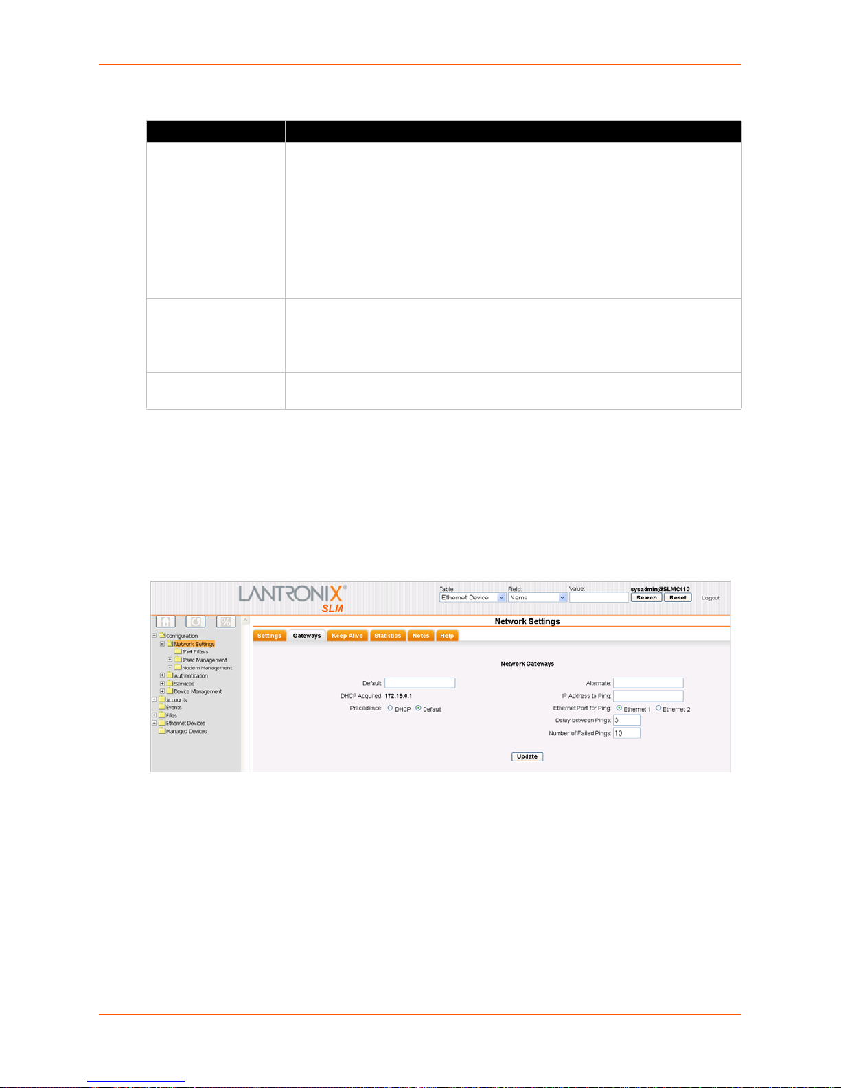
3: Quick Setup
Table 3-13 Network Port Settings
Setting Description
Network Port Settings Disabled: This is the default setting for Network Port 2.
Obtain from DHCP:
DHCP server. (The DHCP server may provide the gateway, depending on its
setup.) This is the default setting for Network Port 1. If you select this option, skip
to step 3.
Obtain from BOOTP:
a BOOTP "server" node. Skip to step 3.
Specify: Requ
generally provides the IP address.
IP Address If specifying an IP address, enter an IP address that will be within a valid range,
unique to your network, and in the same subnet mask as your workstation. There
is no default.
Note: En
Subnet Mask If specifying an IP address, enter the network segmen
There is no default.
ter all IP addresses in dot quad notation.
Acquires IP address, subnet mask, and gateway from the
Lets a network node request configuration information from
ires you to assign a static IP address manually. The administrator
t on which the SLM resides.
3. To save your entries, click Apply. Clic
king Apply commits these changes immediately.
Next, enter network gateway information.
To enter gateway information:
1. On the Network - Settings page, click the
Figure 3-14 Network Settings -Gateways Tab
Gateways tab. The following page opens:
SLM User Guide 41
Page 42

3: Quick Setup
2. Enter the following:
Table 3-15 Network Gateway Setti ng s
Setting Description
Default IP address of the router for this network.
If this has not been set manually, any gateway assigned by DHCP for Network Port 1
or Network Port 2 di
All network traffic that matches the Network Port 1 IP address and subnet mask goes
out Network Port 1. All network traffic that matches the Network Port 2 IP address and
subnet mask goes out Network Port 2.
If you set a default gateway, the SLM sends any network traffic that does not match
Network Port 1 or Network Port 2 to the default gateway for routing.
DHCP Acquired
(view only)
Precedence Indicates whether the gateway assigned by DHCP or the default gateway takes
Gateway assigned by DHCP for Network Port 1 or Network Port 2. The default setting
is None.
precedence. The default setting is Default. If you select DHCP, and both network
ports are configured for DHCP, the SLM gives precedence to the Network Port 1
gateway.
splays.
Note: You
have configured only the settings required to get the SLM up and running . To
complete the network configuration, see Chapter 7: Network and Modem Settings.
To set the local date, time, and time zone:
You can specify the current date, time,
and time zone at the SLM's location (default), or the SLM
can use NTP to synchronize with an NTP server on your network.
1. On the menu, click Con
figuration > Services > Date & Time. The following page opens:
Figure 3-16 Date & Time Page
2. Enter the following information:
SLM User Guide 42
Page 43
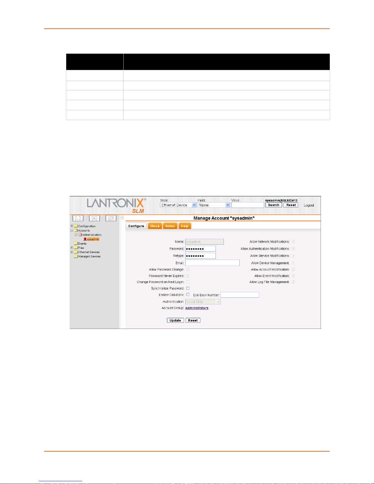
Table 3-17 Date & Time
3: Quick Setup
Date and Time
Setting
Change Date/Time
Date From the drop-down lists, select the curren
Time From the drop-down lists, select the current hour and minute.
Time Zone From the drop-down list, select the appropriate time zone.
SLM Up Time Indicates how long the SLM has been up and running.
3. To save, click Updat
Description
Select the check box to manually enter the date and time at the
t month, day, and year.
e.
To change the administrator password:
The default sysadmin password is PAS
1. On the menu, click Acc
ounts > Administrators > sysadmin. The following page opens:
Figure 3-18 Account Page for Sysadmin
S.
SLM's location.
2. Enter the new administrator password in Password and (Retype). The password can be up to
128 characters and is case sensitive.
3. Click the Upda
te button. When the update is complete, a confirmation message displays.
SLM User Guide 43
Page 44

Quick Setup Command
admin quicksetup
Syntax
admin quicksetup
Description
Displays the quick setup script on the CLI; only th
Next Steps
After quickly getting the SLM up and running, you can complete the configuration on the web
pages.
To learn more about the interfaces, go to Chapter 5: Web and Command Line Interfaces.
3: Quick Setup
e sysadmin account can use this command.
To continue configuring the SLM for your needs, start with Chapter 7: Ne twork and Modem
Settings.
SLM User Guide 44
Page 45

4: Virtual SLM Deployment
The Virtual Secure Lantronix Management (vSLM) Appliance is a virtual appliance that runs under
a variety of virtual machine managers, including VMware. vSLM can be downloaded from the
Lantronix website and launched on a desktop or server, and used to administer Secure Lantronix
Mangement devices like the SLM hardware version. This chapter describes the differences
between the SLM and vSLM.
vSLM is available as a 32-bit VMware version or a OVF (Open Virtualization Format) version. The
VMware version can be launched on VMware Player or VMware Workstation; it can also be
converted for use on VMware ESX and ESXi (see http://kb.vmware.com/kb/900
information on converting the VMware version to a format used by ESX or ESXi). The OVF
version can be launched on VMware ESX and ESXi, both virtual machine managers that support
importing the OVF format.
Minimum Hardware Requirements
3.0 Ghz or faster single core speed
RAM: 2GB
Disk Space: 60 GB
Ethernet: 1 Bridged
for more
Deployment Instructions
Below are instructions for deploying a vSLM VM from the VMware or OVF distribution. Refer to
the documentation for your virtualization manager for specific instructions on opening or launching
a VM.
To deploy the VMware version:
1. Download the vslm-<firmware version>.vmware.zip distribution from the Lantronix
website.
2. Unpack vslm-3.4b.vmware.zip for distribution:
slm-3.4b.vmwarevm/
vslm-3.4b.vmwarevm/vslm-3.4b.vmdk
vslm-3.4b.vmwarevm/vslm-3.4b.vmx
vslm-3.4b.vmwarevm/vslm-VMware-README.txt
3. Launch your virtualization manager and open the unpacked VM.
4. Before starting the VM, configure the following settings:
A minimum of 2GB of RAM
USB enabled
MAC addresses assigned to both network interfaces BEFORE the first boot of the vSLM
sound
Floppy disk and printer support removed
SLM User Guide 45
Page 46

5. Start the VM.
To deploy the OVF version:
4: Virtual SLM Deployment
1. Download the vsl
m-<firmware version>.OVF.zip distribution from the Lantronix
website.
2. Unpack vslm-3.4
vslm-3.4b.OVF/
vslm-3.4b.OVF/vslm-3.4b-disk1.vmdk
vslm-3.4b.OVF/vslm-3.4b.mf
vslm-3.4b.OVF/vslm-3.4b.ovf
vslm-3.4b.OVF/vslm-OVF-README.txt
3. Launch your virtualization manager and open
(see vslm-O
b.OVF.zip for distribution:
or import the unpacked .zip files
VF-README.txt for instructions for using VMware ovftool).
4. Before starting the VM, configure the following settings:
A minimum of 2GB of RAM
USB enabled
MAC addresses assigned to both network interfaces BEFORE the first boot of the vSLM
sound, floppy disk and printer support removed
5. Start the VM
After the VM boots (this may take a few minutes while it
is performing its initial setup), the login
prompt will be displayed on the console. The initial credentials are username "sysadmin" and
password "PASS". After logging in, the settings for the first network interface can be displayed
with the command "show network port 1". The web interface can be accessed with the URL:
https://<IP Address of the first network interface>
At this point you can follow the instruc
with Using Quick Setup on the Command Line Interface on page 37.
It is recommended that the vSLM be sh
reboot" commands, rather than using the virtualization manager to shutdown or restart the vSLM.
30-Day Trial License
The vSLM has a 30-day trial period during which all features are available. At the end of the 30
day trial period, most features will be disabled, and a license will be required to reenable the
features. The current license options can be viewed at the CLI with the "admin showoptions"
command:
[sysadmin@SLMB1DC]> admin showoptions
Physical device location: Disabled
Auto firmware update expiration: apr2014
Virtual Machine: Disabled (2 days remaining in trial
period)
Maximum concurrent users: 25
tions from Chapter 3: Quick Setup for Quick Setup starting
utdown or restarted using its "admin shutdown" and "admin
SLM User Guide 46
Page 47

4: Virtual SLM Deployment
To obtain a permanent vSLM license, contact Lantronix Sales at 800-422-7055. You will need to
provide the unique signature for your vSLM:
[sysadmin@SLMB1DC]> admin signature show
Signature: 6f32deb993d767081dada4ff9a2b27c2
SLM User Guide 47
Page 48

5: Web and Command Line Interfaces
The SLM offers two interfaces for configuring the SLM: a web interface and a command line
interface (CLI). This chapter introduces you to both.
Web Interface
A web interface allows the administrator to configure and manage the SLM using most web
browsers (Internet Explorer 6.0. and later or Firefox 1.5 and later with JavaScript enabled).
Note: Cer
Lantronix devices, require IE 7.
tain features, for example Browse http and Browse https access to some non-
Logging in
To log in to the SLM web interface:
1. Open a web browser (Internet Explorer 6.0. and
enabled).
2. In the URL field, type https:// followe
3. To configure the SLM, use sysadmin as
are the default values.)
Notes:
The administrator may have changed the password using the method described in the
previous chapter.
When SecurID is enabled, the user must enter the number on the RSA token.
Depending on the state of the user, the login page may require a PIN number,
passcode, or new token code.
d by the IP address of your SLM.
the user name and PASS as the password. (These
later or Firefox 1.5 and later with JavaScript
SLM User Guide 48
Page 49

Typical SLM Web Page
Figure 5-2 Tree Structure
The following figure shows a typical web page:
Figure 5-1 Web Page Layout
5: Web and Command Line Interfaces
The web page has the following components:
Search Fields: Enab
SLPs, and SLKs), ports, managed devices, users and persistent
connections in the SLM database.
Menu/Tree: En
to perform a function.
Clicking the expand (plus sign) or contract (minus sign) icon
Clicking the folder or document icon causes the tree structure
Clicking the text only populates the page; the tree structure
Tabs: D
account group, network settings, and Ethernet devices).
Home Button: Di
Reload Button: Us
(another logged-in user) makes changes that affect the database.
Progress Button: In
detection for SLCs, SLMs, SLKs, SLPs, and SCSs.
le you to search for devices (e.g., SLCs,
ables you to display a page to configure settings or
causes the tree structure to toggle between expanded and
contracted views but does not populate the page.
to toggle between expanded and contracted views (for folders)
and populates the page.
remains unchanged.
isplay a series of pages related to a particular entity (e.g.,
splays the Lantronix web site home page.
e to refresh the tree structure after auto-detect, or if some other process
dicates status of background processes such as bulk updates and automatic
SLM User Guide 49
Page 50
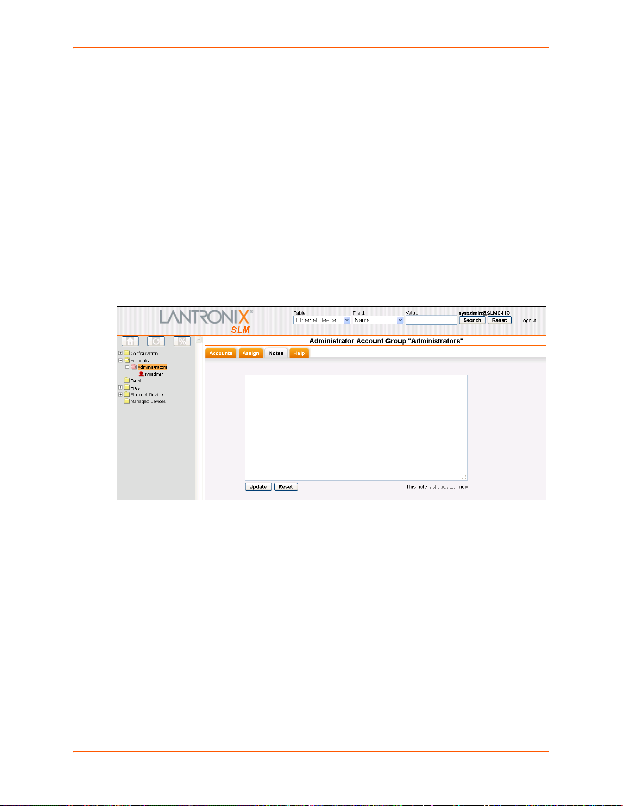
5: Web and Command Line Interfaces
Entry Fields and Options: Enable you to enter data and select configuration options.
Update Button: Makes and s
Reset Button:
Message area: Disp
Sets field contents to their original values.
lays messages such as update confirmations or error messages.
aves the changes immediately.
Notes
Administrators and authorized users can add, update, and delete information about any of the
entities in the system (e.g., account, account group, device, and event) in the form of a note. All
users with permission to view the entity can view notes about it. In this example, we add a note to
an account group.
To view, add, update, and delete a note:
1. On the page for the entity to which you want to ad
the Notes tab. The following page opens.
Figure 5-3 Note for an Account Group
d a note (e.g., Account Group page), click
2. In the text box, type the information you want to associate with the entity.
3. Do one of the following:
To reset the note to its previous contents, click the Reset button.
To delete a saved note, click in the box, press CTRL+A, press Delete, and then click the
Update button.
To save a new note, click the Update button. A confirmation message displays. The next
time you open the page, it displays the note and the date and time of the update.
SLM User Guide 50
Page 51

5: Web and Command Line Interfaces
Web Page Help
To view context sensitive information about any SLM web page:
1. Click the Help ta
b. A Help page opens for the tab you are viewing. The Contents and Search
buttons are above the pane on the left.
Figure 5-4 Example of a Help Page
To search for information:
1. Click the Search
button. A search field displays.
2. Enter the word(s) you want to search for and press Enter.
Note: You
can also enter the word in the search field to the l eft of the Lantronix log o and
press Enter.
SLM User Guide 51
Page 52

5: Web and Command Line Interfaces
Logging Out of the Web Interface
A Logout link is available in the upper right corner of every page.
To log out of the SLM web interface:
1. Click Log
out to the right of the search buttons on the SLM page banner.
Figure 5-5 Logout on the Page Header
Command Line Interface (CLI)
A command line interface is available for entering the commands for the SLM. You can access the
CLI using SSH or a serial terminal connection.
In this User Guide, after each section of
related CLI commands. Not all web page entries have corresponding commands, and vice versa.
The sysadmin user has access to the complete command set, while all other users have access to
a reduced command set.
instructions for using the web interface, you will find
Logging into the CLI
To log in to the SLM command line interface:
1. Do one of the following:
With a serial terminal connection, power up, and when the command line displays, press
Enter.
If the SLM already has an IP address (manually assigned previously or assigned by
DHCP), SSH to xx.xx.xx.xx (the IP address in dot quad notation) and press Enter. The
login prompt displays.
2. To log in as the administrator for setup and configuration:
a. Type sys
b. Type PA
Note: Th
described in the previous chapter.
3. To log in as any other user:
a. Enter your SLM user name and press Enter.
SLM User Guide 52
admin as the user name and press Enter.
SS as the password and press Enter.
e administrator may have changed the password using the methods
Page 53

b. Enter your SLM password and press Enter.
5: Web and Command Line Interfaces
Note: Whe
n SecurID is enabled, the user must enter the number on the RSA toke n.
Depending on the state of the user, the login page may require a PIN number,
passcode, or new token code.
Commands
Commands have the following format:
<action> <category> <parameter(s)>
where
<action>
<category>
devicegroup, account, and network.
<parameter(s)> is on
Command Description
<parameter
name> <aa bb>
<parameter
name> <Value>
Square brackets
is set, show, connect, diag, admin, or logout.
is a group of related parameters you want to configure or view. Examples are
e or more name-value pairs in one of the following formats:
Table 5-6 CLI Commands
Specify one of the values (aa or bb) separated by a vertical line ( | ). The values are
all lowercase and must be entered exactly as shown. Bold indicates a default value.
Specify an appropriate value, for example, a device group name.
This User Guide shows parameter values in mixed case to indicate they are case
sensitive. For example, if you saved a device group name in mixed case, you must
enter it in mixed case; if you saved it in lowercase, you must enter it in lowercase.
Indicate optional parameters.
[ ]
Table 5-7 Actions and Category Options
Action Category
set network | service | ipfilter | account | accountgroup |
auth | nis | ldap | radius | kerberos | tacacs+ | secured
| ethernetdevice | manageddevice | mgroup | datetime |
cli |
menu | sshkey | history | modem | dialaccount |
persisten
t | ipmi | ilo
show network | service | ipfilter | iptables | account |
accountgr
oup | auth | nis | ldap | radius | Kerberos |
tacacs+ | secured | device | port | ethernetdevice |
managedde
vice | auditlog | syslog | portlog | traplog |
eventlog | sessionlog | datetime | cli | menu | sshkey |
history | connection | progress | sysconfig | sysinfo |
modem | dialaccount | routing | persistent | ipmi | ilo
connect device | remote | index | ssh | telnet | tn3270 |
terminate
| persistent | wakeonlan
diag ping | ping6 | arp | traceroute | netstat | nettrace |
internals
SLM User Guide 53
Page 54

5: Web and Command Line Interfaces
Action Category
admin autodetect | locallog | version | option | showoptions |
config | quicksetup | securechannel | signature | banner
| reboot
| shutdown | showbootbank | switchbank |
copybank | web
logout
Terminates CLI session.
Command Help
For general command help, type: help
For more information about a specific command,
type help followed by the command, for example:
help set network
OR
type ? af
ter the command:
set network ?
Tips
Type enough characters to identify the action, category, or parameter name uniquely. For
parameter values, type the entire value. For example,
set network port 1 state static ipaddr 122.3.10.1 mask 255.255.0.0
can be shortened to:
se net po 1 st static ip 122.3.10.1 ma 255.255.0.0
Use the Tab key to automatically complete action, category, or parameter names. Type a
partial name and press Tab to complete the name if only one is possible, or to display the
possible names if more than one is possible.
Should you make a mistake while typing, backspace by pressing the Backspace key or the
Delete key, depending on how you accessed the interface. Both keys work if you use VT100
emulation in your terminal access program when connecting to the console port. Use the left
and right arrow keys to move within a command.
Use the up and down arrows to scroll through previously entered commands. If desired, select
one and edit it. You can scroll through up to 100 previous commands entered in the session.
When the number of lines displayed by a command exceeds the size of the window (the
default is 20), the "Type more to see the next page" message displays. To display the next
page, type more and press Enter. You can override the number of lines (or disable the feature
altogether) with the set cli command.
To clear an IP address, type 0.0.0.0.
Logging Out of the CLI
To log out of the SLM command line interface:
1. Type logout and press Enter.
SLM User Guide 54
Page 55

CLI Commands
The following commands relate to the CLI itself.
set cli terminallines
Syntax
set cli terminallines <disable|1-1000>
Description
5: Web and Command Line Interfaces
Sets the number of lines that display in a page for the a
list. Default is 20.
set history clear
Syntax
set history clear
Description
Clears the CLI command history.
show cli
Syntax
show cli
Description
Displays the terminal lines settings.
show history
Syntax
uditlog, syslog, portlog, traplog, and device
show history
Description
Displays the 100 most recent
Session Commands
connect terminate
Syntax
connect terminate <connect ID> <one or more parameters>
Parameters
outbound <outbound ID>
SLM User Guide 55
CLI commands.
Page 56

5: Web and Command Line Interfaces
You must specify connection ID (inbound ID) to terminate an outbound connection.
Use show connection to
view the current connections and their ID.
Examples
connect terminate 3
connect terminate 3 outbound 1
Description
Terminates a user connection to
the SLM session. Use show connection to view the current
connections and IDs.
show connection
Syntax
show connection
Description
Displays active user connections and connection IDs.
SLM User Guide 56
Page 57

6: Configuration and Operation Overview
To best use the SLM, review the setup and configuration process outlined below before
undertaking the tasks detailed in Chapters 6-10.
Note: Th
roughout this user guide, the term "administrator" means the person using the
sysadmin user name and those members of the Administrators Account Group permitted
to perform the task.
Following is an overview of the tasks the administrato
r and other users perform to configure and
use the SLM, in roughly the order performed.
The typical user employs SLM as follows:
Searches for Lantronix Devices and other Ethernet devices.
Connects by browser, SSH, or Telnet to Lantronix Devices and other Ethernet devices, and
additionally, by secure channel to SLCs and other SLMs.
Accesses notes and logs about the management devices and their ports.
The administrator performs the following con
Updates SLM firmware and configurations.
Configures properties of the log files.
Manages syslog, portlog, auditlog, upgrade, configuration, session, and trap files.
Configures an SNMP agent.
Configures and views events.
Updates firmware on Lantronix Ethernet devices (SLM, WiBox, UDS, Spider, SLP, and SLC).
figuration and maintenance activities:
Step 1: Configure Network Settings
The administrator enters the network settings that enable the SLM to access the network,
manages modems, and sets up IPv4 filter sets
Step 2: Define Authentication Methods
The SLM supports LDAP, RADIUS, NIS, Kerberos, TACACS+, SecurID, and SSH public key
authentication. Remote authentication is optional. The administrator can opt to use only local
authentication.
Step 3: Set Up User Account Groups and Accounts
The SLM comes with four types of account groups: Administrators, Ethernet Device, Managed
Device, and Menu Only users. Administrators create account groups of each type (except
Administrators) and create and assign accounts to the account groups.
The administrator can create additional administr
enabled or disabled:
SLM User Guide 57
ator accounts that have the following rights
Page 58

Network Settings
Authentication
Services (e.g., SNMP and syslog, Date and Time, and Maintenance)
Device Management
Accounts
Events
File Management
Step 4: Auto-Detect Devices
The administrator uses auto-detection methods to find Lantronix devices and other devices on the
network and to add them to the SLM database for the SLM to manage. There is no need to add a
device manually, although that option is available. Currently, auto-detect supports Lantronix
Discovery Protocol (LDP) for SLCs and other Lantronix devices, the Lantronix SCS05/20 device
discovery protocol, and SNMP for SLPs, SLKs, and all other Ethernet devices.
6: Configuration and Operation Overview
Step 5: Associate Account Groups with Ethernet and Managed
Devices
Once the SLM administrator adds account groups and Ethernet devices, the next step is to
associate the account groups with the Ethernet devices and managed devices (devices attached
to Ethernet device's ports) to which they will have access. In the case of SLC/SCS Console
Servers, permissions also allow specific account groups listen-only access or full bidirectional
control.
Step 6: Manage Devices
The user selects Ethernet devices from the menu's tree structure or enters search criteria to
search for Ethernet devices, ports, and managed devices. The user then views port settings (if the
device has ports) and can connect to an attached device through a web browser or the CLI.
For ease of communication and management, managed devices that link together device ports
SLC, SCS, SLK, and SLP) may be created or "fused'' together. Users may then manage all
(e.g.,
of these ports through the managed device on a single web page. In the case of an SLC or another
SLM, the user can make a secure channel connection through which the SLM forwards user
permission information so a secondary login is not required. For SLCs, once a secure channel has
been set up, the user can make a web channel connection.
Step 7: Maintain the SLM
The SLM enables the following maintenance tasks:
SLM Firmware Updates: Th
SLM User Guide 58
e SLM administrator updates the SLM firmware.
Page 59

6: Configuration and Operation Overview
Auto-Save: The administrator saves the configuration of one SLM on another SLM. If there is a
need, the second SLM can "become" the first SLM.
Configuration Save and Restore: The administrat
or saves and restores system configurations,
providing rapid recovery of inadvertent configuration changes.
User Log (Audit Trail):
Every successful login, logout, and command on the command line
interface and web is logged into a database table. The administrator reads this information from
the CLI or web and creates an audit report for one or multiple users.
Events: T
he administrator defines alarms and triggers that constitute an event. Events are sent to
specific users or recorded on the syslog or on another device through an SNMP trap.
Files: The
administrator manages (imports, exports, deletes, and renames) and views upgrade,
configuration, syslog, audit log, port log, sysconfig, device session, and trap files.
SLM User Guide 59
Page 60

7: Network and Modem Settings
This chapter is primarily for the administrator. It explains how to enter the network configuration,
IPv4 filters, and modem settings for the SLM using the SLM web interface or the CLI. If you used a
procedure in Chapter 3: Quick Setup to get your unit up and running on the network, you can add
or update settings here.
IP Address and Other Required Information
Note: On the SLM-02, both Network Ports 1 and 2 are 10/100/1000Base-T. Previous
versions of the SLM have one 10/100Base-T and one 10/100/1000Base-T network port.
The vSLM supports two bridged network adapters.
To configure the unit for use on the network, yo
Network Port 1:
IP address (if not already assigned): ________. ________ . ________ .________
Subnet mask: ________. ________ . ________ .________
Network Port 2: (optional)
IP address (if not already assigned): ________. ________ . ________ .________
Subnet mask: ________. ________ . ________ .________
Default Gateway:
DNS Server: __
Your SLM must have a unique IP address on your network. If you assign an IP address manually,
it must
this information.
The SLM receives an IP address in one of the following ways:
Automatically: T
automatically through DHCP. If you have connected the network port to a network with a DHCP
server, the network port acquires an IP address. Smaller networks may use BOOTP.
Using Detector: This s
an automatically assigned IP address. This utility can be downloaded from the Lantronix website,
by selecting the Secure Lantronix Management SLM product from the Firmware/Downloads page:
www.lantronix.com/support/downloads.
be within a valid range and unique to your network. The administrator generally provides
________. ________ . ________ .________
______. ________ . ________ .________
he first time you power up the SLM, Network Port 1 tries to obtain its IP address
oftware allows you to quickly assign a static IP address to a unit that has
u need the following information:
Manually: If th
an IP address using a terminal or a PC running a terminal emulation program to the unit's serial
console port.
Once the SLM has an IP address, you can configure the remaining settings (and change the IP
ddress, if desired) using the CLI or the web interface.
a
SLM User Guide 60
e SLM cannot obtain an IP address by means of DHCP, you must manually enter
Page 61

Using the Web Interface
After the unit has an IP address, you can configure network parameters that determine how the
SLM interacts with the attached network and enter the date, time, and timezone.
Note: Chapter 5: Web and Command Line Interfaces describes the web interface in
detail.
To log in:
7: Network and Modem Settings
1. Open a web browser (Internet Explorer 7.0. and later or Firefox
enabled).
2. In the URL field, type https:// followe
3. Log in using sysadmin as the user name and PASS as the password. The SLM Configuration
pa
ge opens.
Figure 7-1 SLM Configuration Page (SLM-01 and SLM-02)
d by the IP address of your SLM.
15.0 and later with JavaScript
Figure 7-2 vSLM Configuration Page
SLM User Guide 61
Page 62
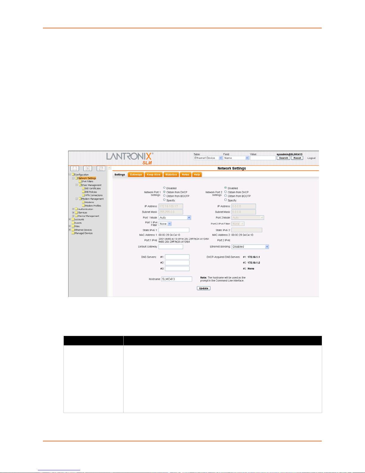
Network Port(s)
Notes:
On the SLM-02, both Network Ports 1 and 2 are 10/100/1000Base-T. Previous versions of the
SLM have one 10/100Base-T and one 10/100/1000Base-T network port.
One possible use for the two Ethernet ports is to have one port on a private, secure network,
and the other on an unsecured network.
Both Ethernet ports should not be on the same subnet.
To enter settings for one or both network ports:
7: Network and Modem Settings
1. On the menu, click Con
figuration > Network Settings. The following page opens:
Figure 7-3 Network Settings Page
2. Enter the following information for one or both network ports:
Network Port Setting Description
Network Port Settings Disabled: This is the default setting for Network Port 2.
SLM User Guide 62
Table 7-4 Network Port Settings
Obtain from DHCP: Acqui
DHCP server. (The DHCP server may provide the gateway, depending on its
setup.) This is the default setting for Network Port 1. If you select this option, skip
to step 3.
Obtain from BOOTP:
a BOOTP "server" node. Skip to step 3.
Specify: Requires you to assign a static IP address manually. The administrator
generally provides the IP address.
res IP address, subnet mask, and gateway from the
Lets a network node request configuration information from
Page 63

7: Network and Modem Settings
Network Port Setting Description
IP Address If specifying an IP address, enter an IP address that is within a valid range, unique
to your network, and in the same subnet mask as your workstation. There is no
default.
Note: Enter all IP addresses in dot quad notation.
Subnet Mask If specifying an IP address, enter the network segment on which the SLM resides.
There is no default.
Port Mode The method of data transmission (Auto, Half-Duplex, or Full-Duplex).
Port 1 and Port 2 IPv4
Filter
Static IPv6 IPv6 addresses are written as 8 sets of 4-digit hexadecimal numbers separated by
MAC Address
(display only)
Port IPv6 (display
only)
Default Gateway IP address of the router for this network.
If you have added filter sets on the IPv4 Filter Definitions page, select the desired
one. (See IPv4 Filters.)
colons. There are several rules for modifying the address. For example,
1234:0BCD:1D67:0000:0000:8375:BADD:0057 may be shortened to
1234:BCD:1D67::8375:BADD:57.
Note: The SLM stores all IP addresses internally using IPv6 format. When
rendering these addresses for display, the SLM uses IPv4 unless the address
cannot be displayed in that format, in which case it uses shortened IPv6.
Also referred to as the Hardware or Ethernet address.
IPv6 addresses active on this network port.
If this has not been set manually, any gateway acquired by DHCP for Network Port
1 or Network Po
All network traffic that matches the Network Port 1 IP address and subnet mask
goes out Network Port 1. All network traffic that matches the Network Port 2 IP
address and subnet mask goes out Network Port 2.
If you set a default gateway, the SLM sends any network traffic that does not
match Network Port 1 or Network Port 2 to the default gateway for routing.
rt 2 displays.
SLM User Guide 63
Page 64

7: Network and Modem Settings
Network Port Setting Description
Ethernet Bonding Ethernet bonding is a way of joining two Ethernet interfaces into a single virtual
interface for redundancy and/or load balancing. The SLM supports four types of
Ethernet bonding in addition to the default state of disabled.
Note: With bonding enabled, the IP/netmask settings for network port 1 are
applied to the virtual bonding interface.
Select one of the following:
Active Backup: Only one of the two Ethernet interfaces will be active (involved in
transmitting and receiving data) at any one time. If the SLM detects that the
Ethernet interface has lost network connectivity, the system makes the secondary
interface the new active one after a few seconds (~3.5 - 4) of delay. (This delay
length is also used with the other bonding settings.)
802.3ad Layer 2: IEEE 8
load-balancing strategy that uses the destination MAC address as the criterion for
determining which interface to send each data frame out of.
802.3ad Layer 3+4: Much like 802.3ad Layer 2, but uses the destination IP and
TCP/UDP port number to determine which interface to send data from.
Note: Both 802.3ad bonding modes require that both network interfaces share the
same speed/duplex modes. This rule is currently enforced by the web interface,
but not by the CLI.
Adaptive Load Balancing: This mode determines which interface to send data
from by looking at the current load on each interface. It also controls which
interface will receive a response by modifying the SLM's ARP replies before they
are sent out. If a link failure occurs on one of the network ports, the system will fail
over to the other interface.
Note: In
require any special network switch configuration, while the two 802.3ad modes do.
The active-backup mode is recommended for most situations, as redundancy
tends to be a more important goal than the relatively small increase in bandwidth
(note that bonding two interfaces for load balancing does not double the available
bandwidth because of protocol overhead issues).
theory, the active-backup and adaptive load balancing modes do not
02.3ad-compliant dynamic link aggregation. This is a
3. Configure up to three name servers, either by entering the IP addresses or by accepting the IP
addresses assigned by DHCP:
Table 7-5 DNS Servers
IP Address Setting Description
#1 IP address of the primary name server. Thi
configure DNS (Domain Name Server) servers. Note: Assigning DNS servers allows
FQDNs to be used in place of most IP addresses throughout the system.
#2 (optional) IP address of the secondary DNS name server.
#3 (optional) IP address of the tertiary DNS name server.
DHCP-Acquired
DNS Serv
only)
ers (view
DNS servers automatically assigned by DHCP. The default setting for up to three
servers is None.
s entry is required if you choose to
4. Enter the following:
SLM User Guide 64
Page 65

7: Network and Modem Settings
Table 7-6 Hostname
Hostname Setting Description
Hostname The default hostname is SLM. You can specify a fully qualified domain name (for
example, SLM.lantronix.com). There is a 64-character limit (contiguous characters,
no spaces).
Note: The hostname becomes the prompt in the command line interface.
5. To save your entries, click the Update button.
Network Gateways
You can enter network gateway information.
To enter gateway information:
1. On the Network - Settings page, click the Gat
Figure 7-7 Network Settings -Gateways Tab
eways tab. The following page opens:
SLM User Guide 65
Page 66

2. Enter the following:
7: Network and Modem Settings
Table 7-8 Network Gateway
Network Gateway
Setting
Default IP address of the router for this network.
DHCP Acquired
(view only)
Precedence Indicates whether the gateway assigned by DHCP or the default gateway takes
Alternate An alternate IP address of the router for this network, to be used if an IP address
IP Address to Ping IP address to ping to determine whether to use the alternate gateway.
Ethernet Port to
Ping
Delay between
Pings
Number of Failed
Pings
Description
If this has not been set manually, any gateway assigned by DHCP for Network Port
1 or Network Port 2 displays.
All network traffic that matche
goes out Network Port 1. All network traffic that matches the Network Port 2 IP
address and subnet mask goes out Network Port 2.
If you set a default gateway, the SLM sends any network traffic that does not match
Network Port 1 or Network Port 2 to the default gateway for routing.
Gateway assigned by DHCP for Network Port 1 or Network Port 2. The default
setting is None.
precedence. The default setting is Default. If you select DHCP, and both network
ports are configured for DHCP, the SLM gives precedence to the Network Port 1
gateway.
lly accessible through the default gateway fails to return one or more pings.
usua
Ethernet port to use for the ping.
Number of seconds between pings
Number of pings that fail before the SLM uses the alternate gateway.
s the Network Port 1 0IP address and subnet mask
3. To save your entries, click the Update button.
Keep Alive
Keep Alive settings keep TCP connections active and monitor for connections that are no longer
active.
To enter Keep Alive settings:
1. Click the Keep A
2. Enter the following information:
Keep Alive Setting Description
Start Probes Number of seconds the SLM wai
Number of Probes Number of probes the SLM sends before closing a session. The default is 5.
Interval The number of seconds the SLM waits between probes. The default is 60 seconds.
SLM User Guide 66
live tab.
Table 7-9 Keep Alive Settings
ts after the last transmission before sending the
first probe to determine whether a TCP session is still alive. The default is 600
seconds (10 minutes).
Page 67
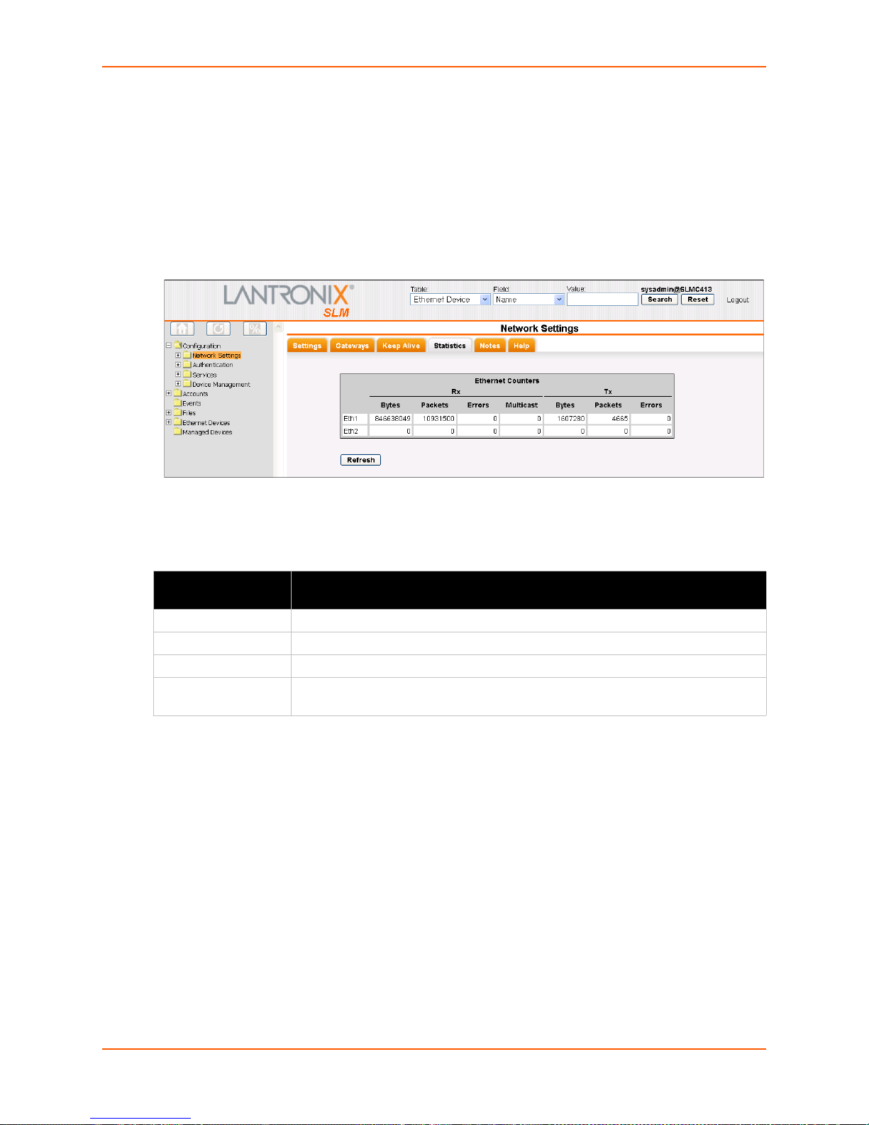
3. To save your entries, click the Submit button.
Viewing Network Statistics
You can check Ethernet counters for the network port(s).
To view network statistics:
7: Network and Modem Settings
1. On the Network - Settings page, click the St
Figure 7-10 Network Settings - Statistics Tab
atistics tab. The following page opens:
Statistics include the following:
Table 7-11 Counters for Rx and Tx Transmissions
Network Statistic
Setting
Bytes Number of bytes received or transmitted through this Ethernet interface.
Packets Number of Ethernet packets received or transmitted through the interface.
Errors Number of received or transmitted packets with physical layer errors.
Multicast (Tx only) Number of received or transmitted packets wi
Description
th the destination address equivalent
to a multicast address.
Changing the Current User's Password
Users logged in locally (not using remote authentication) may change passwords at any time,
unless the administrator has disabled this option.
To change your password:
1. On the menu, click Con
2. Click the Password tab. The
SLM User Guide 67
figuration. The Configuration Home page opens.
following page opens:
Page 68

Figure 7-12 Configuration Page - Password Tab
3. Enter the New Password and Retype fields.
7: Network and Modem Settings
4. Click the Upda
te button.
Network Commands
admin quicksetup
Syntax
admin quicksetup
Description
Displays the quick setup script on the CLI; only th
set network dns
Syntax
set network dns <1|2|3> ipaddr <IP Address>
Description
Configures up to three DNS servers.
set network gateway
Syntax
set network gateway <parameters>
e sysadmin account can use this command.
Parameters
default <IP Address>
precedence <dhcp|default>
alternate <IP Address>
pingip <IP Address>
ethport <1 or 2>
pingdelay <1-250 seconds>
failedpings <1-250>
SLM User Guide 68
Page 69

7: Network and Modem Settings
Description
Sets the default gateway.
set network host
Syntax
set network host <Hostname>
Description
Sets the SLM hostname.
set network port
Syntax
set network port <1|2> <parameters>
Parameters
state <dhcp|bootp|static|disable>
[ipaddr <IP Address> mask <Mask>]
mode <auto|10mbit-half|100mbit-half|10mbit-full|100mbit-full>
[ipfilter <IPv4 Filter Name | CLEAR>]
CLEAR removes the IP filter assignment.
Description
Configures Network Port 1 or 2.
show network all
Syntax
show network all
Description
Displays all network settings.
show network port
Syntax
show network port <l|2>
Description
Displays Network Port 1 and Network Po
show network settings
Syntax
show network settings
Description
Displays all network settings.
rt 2 connection information.
SLM User Guide 69
Page 70

IPv4 Filters
Warning: IPv4 filters configuration is a feature for advanced users. Adding and
7: Network and Modem Settings
enabling IPv4 filter sets incorrectly can disable your SLM.
IPv4 Filters act as a firewall to allow or deny individ
protocols. On the IPv4 Filter Definitions pages, the administrator defines and edits IPv4 filter sets
and displays the current system-recognized filters.
ual or a range of IP addresses, ports, and
Viewing a List of IPv4 Filters
Each IPv4 filter set is composed of one or more filter rules.
To view a list of available IPv4 filters se ts :
1. On the menu, click Con
displays a list of existing filters.
figuration > Network Settings > IPv4 Filters. The following page
Figure 7-13 IPv4 Filter Definitions - List Tab
2. View the list of filters and the associated comments.
Adding an IPv4 Filter
Note: User-created IPv4 filter sets display on the menu tree and are composed of one or
more filter rules. When a network connection or modem is configured to use an IPv4 filter
set, all network traffic through that connection is compared, in orde r, to the rules of that
filter set. Network traffic may be allowed to pass, it may be dropped (without notice), or it
may be rejected (sends back an error packet) depending upon the rules of that filter set.
To add an IPv4 filter:
1. On the List tab, click the Add New Filte
r button. The Configure tab displays.
SLM User Guide 70
Page 71

7: Network and Modem Settings
Figure 7-14 New IPv4 Filter Definition - Configure Tab
Note: A new filter set is initialized with a rule to allow all established TCP connec t ion s.
You may remove this rule from your filter set, but do so with caution as loss of connectivity
may result.
2. Enter the following for eac
Table 7-15 IPv4 Filter Def
IPv4 Filter Setting Description
IP[/mask] or IP1IP2
(optional)
Protocol From the drop-down list, select the type of protocol
Port Range Enter a range of destination port numbers to be tested. An entry is required for TCP,
Action Select whether to drop, reject, or allow communications from IPv4 addresses within
Filter Name Name that identifies a filter. The name may be composed of letters, numbers and
Specify any IP address, IP prefix with mask, or IP range.
Examples:
172.19.220.64 - this specific IP address only
172.19.0.0/16 - IP addresses 172.19.0.0 - 172.19.255.255
172.19.0.128 - 172.19.64.0 - IP addresses in this range
operate. The default setting is All.
TCP New, TCP Established, and UDP, and is not allowed for other protocols.
Separate multiple ports with commas. Separate ranges of ports by colons.
Examples:
22 - filter on port 22 only
23,64,80 - filter on ports 23, 64 and 80
23:64,80,143:150 - filter on ports
the specified range. Drop ignores the packet with no notification. Reject ignores the
packet and sends back an error message. Allow permits the packet through the filter.
hyphens only. (The name cannot start with a hyphen.)
Example: F
h filter in the set:
inition - Configuration Tab
(if any) through which the filter will
23 through 64, port 80 and ports 143 through 150
ILTER-2
SLM User Guide 71
Page 72

7: Network and Modem Settings
IPv4 Filter Setting Description
Save as new filter
definition
Comment
(optional)
Generate filter to
w the specified
allo
protocol or service
Select to make small changes to an existing filter set and then save it as a new filter
set. If you select this option, you must supply a Filter Name that does not already
exist.
Enter information related to the filter. It displays next to the filter name on the List tab.
You may wish to "punch holes" in your filter set for a particular protocol or service. For
instance, if you have configured your NIS server and wish to create an opening in your
filter set, select the NIS option and click the Add Filter button. This entry adds a new
rule to your filter set using the NIS -configured IP address. Other services and
protocols added automatically generate the necessary rule to allow their use.
3. Click the right arrow button to add the new rule to the bottom of the list box on the right, or
click the Add Filter button to add a predefined rule to the bottom of the list box.
4. To remove a rule from the filter set, highligh
t that line and click the left arrow. The rule
populates the rule definition fields, allowing you to make minor changes before reinserting the
rule. To clear the definition fields, click the Clear button.
5. To change the order of priority of the rules in the list box, select
the rule to move and use the
up or down arrow buttons on the right side of the filter list box.
6. To save, click the Updat
e button. A confirmation message displays, and the new filter displays
in the menu tree.
Note: T
o add another new filter, return to the List tab (step 1).
Updating or Deleting an IPv4 Filter
The administrator can update or delete IPv4 filters.
To update or delete an IPv4 filter:
1. On the List
tab, click the Edit icon to the left of the filter. The Configure tab displays.
SLM User Guide 72
Page 73

7: Network and Modem Settings
Figure 7-16 IPv4 Filter - Configure Tab
2. To delete a filter:
Note: You
may not delete a filter set currently referenced by a network inte rface or a
modem.
a. Click the Delete bu
tton.
b. In response to the request for confirmation, click OK.
c. Click IPv4 Filters on
the menu tree. The deleted filter is no longer on the menu tree or
listed on the List tab.
3. To update an IPv4 filter:
a. Edit the information as desired.
b. Click the Upda
te button. A confirmation message displays.
SLM User Guide 73
Page 74
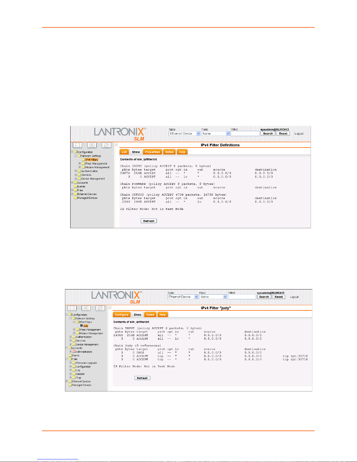
7: Network and Modem Settings
Viewing the System IPv4 Filter Sets
The administrator may view a list of all IPv4 filter sets (user and system) or an individual IPv4 filter
set.
To view all filter sets:
1. On the menu, click IPv4 Fi
2. Click the Show ta
b. The following page opens:
lters. The List tab displays.
Figure 7-17 IPv4 Filter Definitions - Show Tab
To view an individual IPv4 filter set:
1. On the menu, click the individual filter set name. The IPv4 Filter page for the filter set displays.
2. Click the Show tab.
Figure 7-18 IPv4 Filter - Show Tab
SLM User Guide 74
Page 75
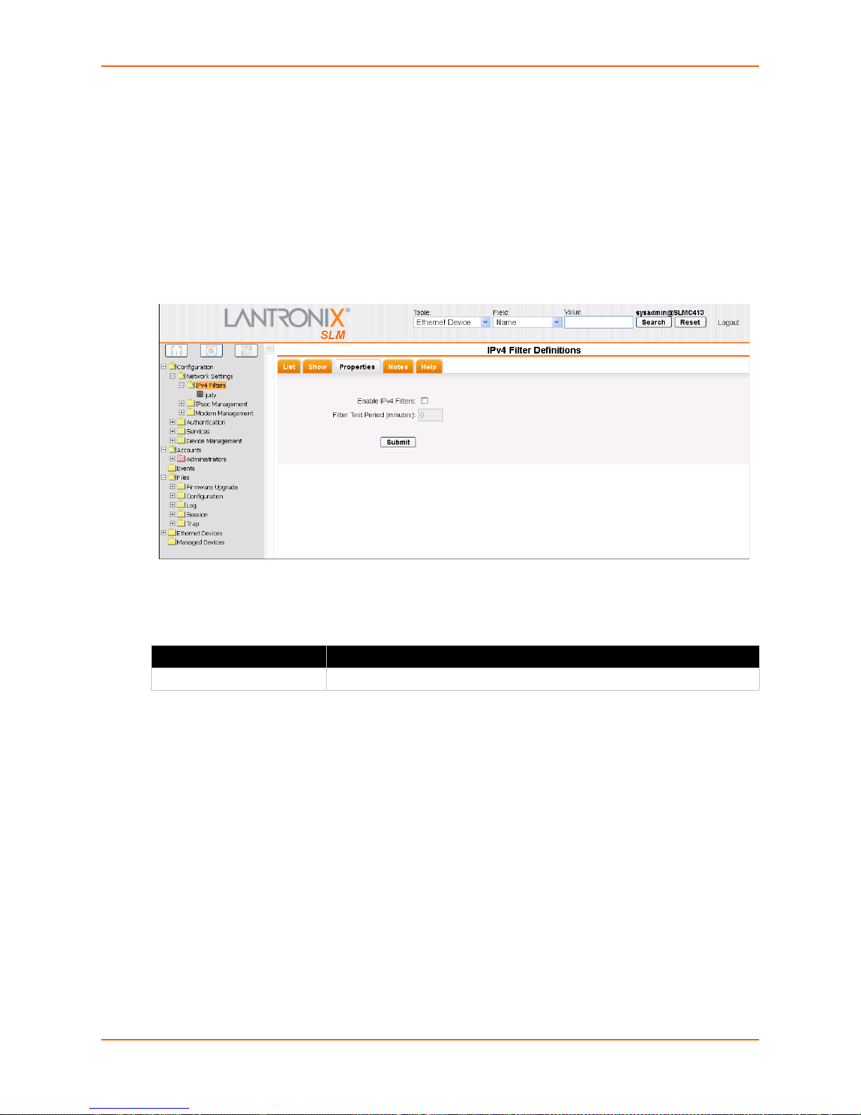
7: Network and Modem Settings
Setting Properties of an IPv4 Filter
For IPv4 filters to be in effect, the Enable IPv4 Filters check box must be selected on the
Properties tab.
To enable and test the IPv4 filter:
1. On the menu, click IPv4 Fi
2. Click the Prop
erties tab.
Figure 7-19 IPv4 Filter Definitions - Properties Tab
3. Enter the following:
Table 7-20 IPv4 Filter Definitions - Properties Tab
lters. The IPv4 Filter Definitions page displays.
IPv4 Filter Setting Description
Enable IPv4 Filters To enable the filters, select the check box. Disabled by default.
SLM User Guide 75
Page 76

7: Network and Modem Settings
IPv4 Filter Setting Description
Filter Test Period (minutes) Note: There may be times when a complex IPv4 filter set may accidentally
lock all users out of the SLM. To allow testing of new filter sets, the
administrator can enable and test the filter sets for a specified period.
Before enabling an untested complex filter, enter the number of minutes you
would like filters to be active before being automatically disabled.
A zero (0) in this field indicates that filtering will not be automatically
disabled, and the Enable IPv4 Filters state you specified will take place
immediately.
A non-zero value is the number of minutes until IPv4 filters are disabled,
whether or not a lockout condition occurs.
Example:
You set this value to 5 and enable IPv4 filters. If your system locks up
because of a bad filter set definition, then in five minutes, filtering will
automatically be disabled. Note that even if there are no problems with
the filter set, IPv4 filtering will still be disabled in 5 minutes. Once you
are satisfied with the IPv4 filter definitions, return to this page and set
the Filter Test Period to 0 and resubmit to enable IPv4 filtering
permanently.
Note: If you submit a new Filter Test Period (larger than 0) when the IP filter
is already in test mode, the test timer resets to the new test period and starts
test mode again. If you submit a zero Filter Test Period when the IP filter is
in test mode, the test mode stops, and the specified Enable IPv4 Filters
state takes effect immediately. If you have physical access to the SLM, you
can always disable IPv4 from the console using the CLI.
4. To save, click the Submit button.
5. In response to the confirmation request, click OK. A co
message area.
Note: To
determine whether the IPv4 filter is still in test mode, when the test mode was
started, and how long until the test mode ends, click the Show tab on the IPv4 Filters page
or on an individual IPv4 Filter Set page.
IPv4 Filter Commands
set ipfilter delete
Syntax
set ipfilter delete <Name>
Example:
set ipfilter delete MyFilter
Description
Deletes IPv4 filter set by sp
set ipfilter delete all
nfirmation message displays in the
ecified name.
Syntax
set ipfilter delete all
SLM User Guide 76
Page 77

Description
7: Network and Modem Settings
Deletes all referenc
es to filters.
set ipfilter delete interactive
Syntax
set ipfilter delete interactive
Description
Deletes IPv4 filters by
interactive mode.
set ipfilter name delete
Note: Type
show ipfilter name <Name> or show ipfilter index
<number> to display the rule number.
Syntax
set ipfilter delete name <Name> [rule <rule number>]
Example
set ipfilter delete MyFilter rule 3
Description
Deletes IPv4 filter rule by specified name and rule number.
set ip filter state
Syntax
set ipfilter state <enable|disable>
Description
Enables or disables IPv4 filters.
set ipfilter test
Syntax
set ipfilter test <number of minutes>
Description
Enables or disables IPv4 filter test mode.
show ipfilter
Note: Type s
how ipfilter to display index.
Syntax
show ipfilter <parameters>
Parameters
[name <Filter Name>]
[index <number>]
SLM User Guide 77
Page 78
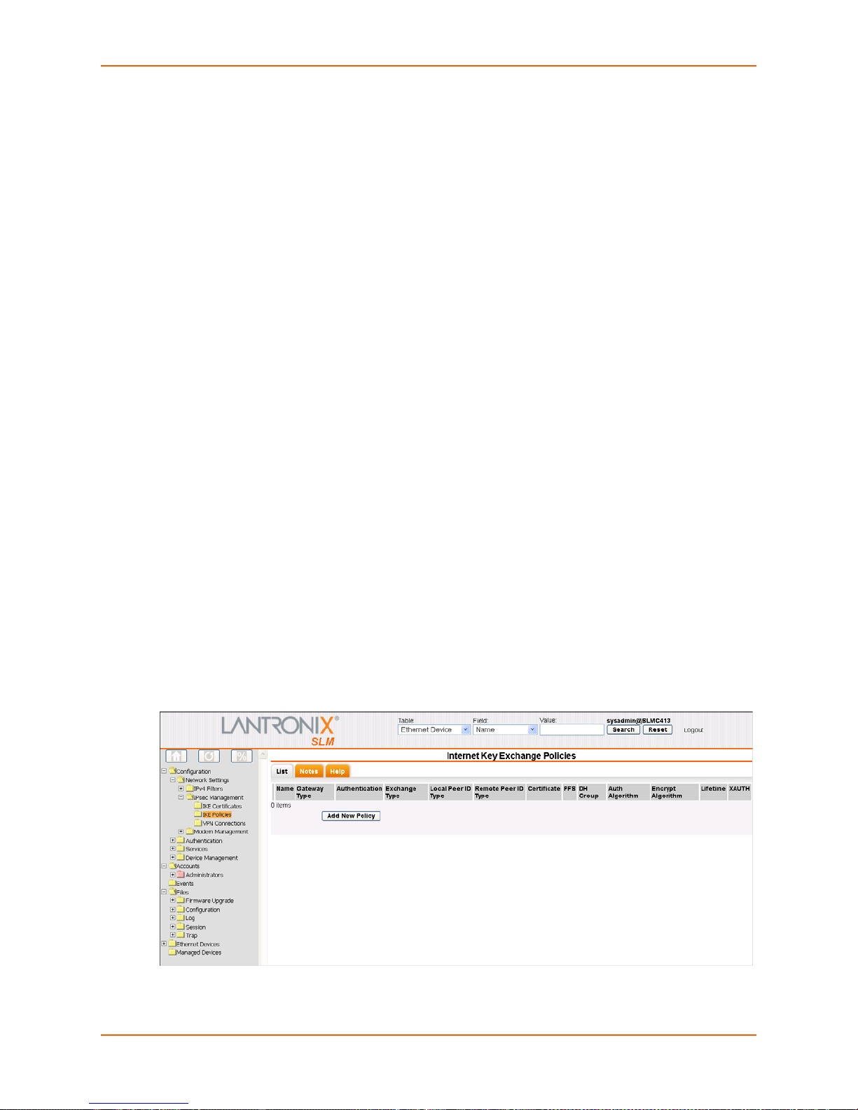
Examples
show ipfilter
show ipfilter name MyFilter
show ipfilter index 2
Description
7: Network and Modem Settings
Displays IPv4 filter
show iptables
Syntax
show iptables
Description
Displays all IP filtering ru
information.
IPsec Management
Internet Protocol Security (IPsec) for the SLM includes IKE policy for internet key exchanges and
Virtual Private Network connections.
Internet Key Exchange (IKE) Policies
The administrator can view, add, and update one or more IKE policies.
Viewing a List of IKE Policies
The administrator can view IKE Policies.
To view a list of available IKE policies:
les for all chains.
1. On the menu, click IPse
current IKE policies.
Figure 7-21 Internet Key Exchange Policies Page
c Management > IKE Policies. The following page displays, listing
SLM User Guide 78
Page 79

7: Network and Modem Settings
2. View the list of policies and associated information:
Table 7-22 Ike Policy Exchange Information
Ike Policy Setting Description
Name Name identifying the IKE policy.
Gateway Type IPv4 or IPv6 type of address.
Authentication Method of verifying da
PSK: Pre-Shared Key uses a password exchange and matching process.
Exchange Type Mode during the security association phase of the key exchange.
Note: Agg
Local Peer ID Type Local SLM identification type:
IPv4:
IPv6:
FQDN: Fully Qualified Domain Name
User Email: Ema
Remote Peer ID Type Remote host or gateway identification type.
Certificate Note: This
PFS Perfect Forward Secrecy (PFS) ensures that a given IPsec SA key was not derived
from any other secret, such as another key. Enabled by default.
DH Group Diffie-Hellman key group (DHx) used for an encryption key.
Authentication
Algorithm
Encryption
Algorithm
Lifetime Duration in seconds before a key expires.
XAUTH XAUTH in use.
From the drop-down list, select an algorithm for verifying data integrity:
SHA1:
MD5: Me
SHA2-256: 256-bit Secure Hash Algorithm
Method of encrypting data, in order
3DES: Data Encryption Standa
AES: Ad
AES-192:
AES-256:
ressive mode will be available in a future release.
Internet Protocol version 4
Internet Protocol version 6
feature will be available in a future release.
Secure Hash Algorithm 1
ssage Digest
vanced Encryption Standard
192-bit key with AES encryption
256-bit key with AES encryption
ta integrity:
il address of the local user
of security level provided:
rd
SLM User Guide 79
Page 80

Adding an IKE Policy:
The administrator can add an IKE policy.
To add a new IKE policy:
7: Network and Modem Settings
1. On the List
tab, click the Add New Policy button. The Configure tab displays.
Figure 7-23 Add Internet Key Exchange Policy Page
2. Enter the following information:
Table 7-24 Add Internet Key Exchange Policy - Configure Tab
Ike Policy Setting Description
Policy Name Enter a name to identify the IKE policy. Must be 1-63 characters, including digits,
letters, hyphens, and underscores.
Gateway Address
Type
Remote Gateway
ss
Addre
Authentication
Method
Exchange Type Select the mode during the security associ
From the drop-down list, select the version of the Internet Protocol used for
theaddress:
IPv4: Internet Pro
IPv6: In
Enter the IP address of the remote end of the gateway.
From the drop-down list, select the method of verifying data integrity:
PSK:
RSA
signature.
Note: This feature will be available in a future SLM release.
Main Mode: (default)
Note: Ag
ternet Protocol version 6
Pre-Shared Key uses a password exchange and matching process. (default)
Signature: Uses a private and public key that together comprise a digital
gressive mode will be supported in a future release.
tocol version 4 (default)
ation phase of the key exchange:
SLM User Guide 80
Page 81

7: Network and Modem Settings
Ike Policy Setting Description
Local Peer ID Type From the drop-down list, select the method of filtering incoming data.
IPv4:
Internet Protocol version 4
IPv6: Internet Protocol version 6
FQDN:
User Email: Email address of the local user
Local Peer ID Value Enter the local SLM identificatio
Type setting.
Remote Peer ID
Type
Remote Peer ID
Value
Certificate File Note: This feature will be available in a future release.
PSK Value Enter the value of a pre-shared key.
PFS Select the checkbox to enable PFS (Perfect Forward Secrecy). PFS ensures that a
DH Group Initial Diffie-Hellman value.
Authentication
Algorithm
Encryption
Algorithm
XAUTH Select to use a "group" shared secret rathe
Lifetime Enter the duration in seconds before a key expires. Defaul
Login Enter the username for XAUTH.
Password
Select the method of filtering outgoing data:
IPv4: Internet Protocol version 4 (default)
IPv6: In
FQDN:
User Email: Email address of the remote user
Enter the identification value of the
given IPsec SA key was not derived from any other secret, such as another key.
Enabled by default.
MODP1024
MODP1536
MODP2048
From the drop-down list, select an algorithm for verifying data integrity:
SHA1:
MD5:
SHA2-256: 256-bit Secure Hash Algorithm
From the drop-down list, select the method of
of security level provided):
3DES: Da
AES: Advance
AES-192: 192-b
AES-256: 256-b
authentication. Disabled by default.
Enter the password for XAUTH.
Fully Qualified Domain Name
n value. This value depends on the Local Peer ID
ternet Protocol version 6
Fully Qualified Domain Name
remote host or gateway.
Secure Hash Algorithm 1.
Message Digest 5.
encrypting data (listed below in order
ta Encryption Standard
d Encryption Standard
it key with AES encryption
it key with AES encryption
r than digital certificates for
Note: This feature will be available in a future SLM release.
t is 3600.
3. To save your entries, click the Submit button.
SLM User Guide 81
Page 82

Updating or Deleting an IKE Policy
The administrator can update or delete IKE policies.
To update or delete a policy:
7: Network and Modem Settings
1. On the List
tab, click the Edit icon to the left of the policy. The Configure tab displays.
Figure 7-25 Internet Key Exchange Policiy -- Configure Tab
2. To delete a policy:
Note: You
may not delete a policy currently referenced by a VPN.
a. Click the Delete bu
tton.
b. In response to the request for confirmation, click OK.
c. Click IK
E Policies on the menu bar.
3. To update a policy:
a. Edit the information as desired.
b. Click the Upda
4. To save your entries, click the Save bu
te button. A confirmation message displays.
tton.
SLM User Guide 82
Page 83

VPN Connections
The administrator can view, add, or update one or more Virtual Private Networks (VPNs). Each
VPN must reference an IKE Policy. You can only delete an IKE Policy that is not referenced by a
VPN.
Viewing a List of VPNs
The administrator can view a list of VPNs.
To view a list of VPNs:
7: Network and Modem Settings
1. On the menu, click Con
figuration > Network Settings > IPsec Management > VPN
Connections. The following page displays:
Figure 7-26 VPN Connections Page
2. View the following information about each VPN:
Table 7-27 VPN Connection Settings
VPN Connection
Setting
Name Name that identifies VPN.
IKE Policy IKE policy that references this VPN.
Encapsulation Mode Tunnel mode: Used whe
Remote Address
Type
Network Port Network port on the SLM that connects to the VPN.
Local Protocol IP protocol selected to protect data traffic.
Local Port Method selected to protect data traffic on the TCP port of the SLM.
Subnet Prefix Subnet prefix length for Subnet type clients.
Auth Algorithm Algorithm for verifyi
Description
n the remote peer is an IPSec gateway.
Host mode: Used whe
Subnet type: The subnet that is the destination of the IPsec traffic.
Single:
The single host that is the destination of the IPsec traffic.
n the remote peer is an IPsec host.
ng data integrity.
SLM User Guide 83
Page 84

7: Network and Modem Settings
VPN Connection
Setting
Encrypt Algorithm Method of encrypting data, in ascending order of security level provided:
Lifetime Duration in seconds before a key expires.
Active Indicates whether the VPN is ready to be connected.
Status Indicates whether the VPN is connected or disconnected.
Description
3DES (Data Encryption Standard)
Advanced Encryption Standard (AES)
AES-192: 192-bit key with AES encryption
AES-256: 256-bit key with AES encryption
Adding a VPN
Administrators may add VPNs.
1. On the List tab, click the New VPN Connection bu
Table 7-28 Add VPN Connection Settings
VPN Connection
Setting
VPN Name Enter a name to identify the VPN.
Encapsulation Mode Tunnel mode: Used when the remote peer is an IPSec gateway.
Network Port Select the network port connecting to the VPN.
Protocols Select the protocol used in the VPN connection:
Port Select the type of security used on the port:
IKEPolicy IKE Policy that refe
Remote Peer
dress Type
Ad
Remote Peer IP Start Starting IP address in a range of remote IP addresses.
Subnet Prefix Prefix of the subnet for Subnet Type peers.
Description
Host mode: Used
ALL: All
TCP: Tran
UDP: User Datagram Protocol
ICMP:
ICMPv6: Internet Control Messag
IGMP: Internet Group Management Protocol
All
SSH
Telnet
FTP Data
FTP Control
HTTP
RLOGIN
TFTP
Subnet type: The subnet that is the destination of the IPsec traffic.
Single:
of the listed protocols are used.
Internet Control Message Protocol
The single host that is the destination of the IPsec traffic.
when the remote peer is an IPsec host.
smission Control Protocol
rences this VPN.
tton. The Configure tab displays.
e Protocol version 6
SLM User Guide 84
Page 85

7: Network and Modem Settings
VPN Connection
Setting
Authentication
Algorithm
Encryption
Algorithm
SA Lifetime Duration in seconds before an IPsec Security Association (SA) expires. The default
Active Select to activate the VPN.
Description
From the drop-down list, select the algorithm for verifying data integrity:
None
SHA1:
MD5:
SHA2-256:
From the drop-down list, select the method
3DES (Data Encryption Standard)
AES
AES-192
AES-256
is 2
8800.
of encrypting data:
2. To save, click the Submit button.
Updating or Deleting a VPN
To update or delete a VPN:
1. On the List tab, click the Edit icon to the left of the policy.
The Configure tab displays.
Figure 7-29 VPN Connection -- Configure Tab
2. To delete a VPN:
a. Click the Delete bu
tton.
b. In response to the request for confirmation, click OK.
c. Click VPN Conn
ections on the menu bar.
3. To update a policy:
a. Edit the information as desired.
b. Click the Upda
4. To save your entries, click the Save bu
SLM User Guide 85
te button. A confirmation message displays.
tton.
Page 86

Connecting a VPN
To connect a VPN:
7: Network and Modem Settings
1. On the List
tab, click the Edit icon to the left of the VPN. The VPN Connection page
displays.
2. Make sure you have updated the connection.
3. Select the Active checkbox (if no
4. Click the Co
nnect button. It will take a couple of seconds before the connection is established.
Modem Management
Dial-up modem support ensures access when the network is not available. SLM supports dial-in
(text mode and PPP mode) and dial-out (PPP mode) as follows:
The administrator can configure dial-in and dial-out from either the web interface or the CLI.
A user dialing in from a remote computer in text mode can access the CLI on the SLM.
A user dialing in from a remote computer in PPP mode can access the CLI and the web
interface on the SLM. Depending on the PPP settings, the user may access all devices that
the SLM has access to as well.
A user can dial out from the CLI and the web interface in PPP mode.
Viewing a List of Modems
The administrator can view a list of the SLM's internal and external modems.
t already selected).
Note: Curr
ently, the SLM-01 and SLM-02 support PCI and USB modems. The vSLM
supports USB modems only. See Discovering a USB Modem. SLM does not support
plug-and-play.
To view a list of available modems:
1. On the menu, click Con
figuration > Network Settings > Modem Management > Modems.
The following page displays.
SLM User Guide 86
Page 87

Figure 7-30 Modems Page
2. View the following information about each modem:
Table 7-31 Modem - List Tab
7: Network and Modem Settings
Modem Setting Description
Name Name that identifies the modem.
Modem Type Identifies the type of modem (e.g., PCI or USB).
Baud Communication speed between the SLM and a modem.
Data Bits Number of data bits used to transmit a character.
Parity Type of parity checking. Parity checkin
Stop Bits Number of stop bit(s) used
Flow Control Method of preventing buffer overflow and loss of data.
Mount Point Name of the serial interface device to which the modem is assigned.
Connection Name of connection assigned for dial-in. See Enabling or Disabling Dial-in
Connections on page 89.
IPv4 Filter Set IPv4 filter being used.
Inbound Enabled Indicates whether the modem is enabled to receive dial-in calls.
Status Indicates whether the modem is currently connected.
3. To disconnect a connection, select
its check box and click the Disconnect button.
to indicate that a byte of data has been transmitted.
g detects simple, single-bit errors.
Configuring a Modem
The administrator can configure the modem for an incoming connection from a remote device or
computer.
To configure a modem:
1. Select the modem and click the Conf
SLM User Guide 87
igure tab. The following page opens:
Page 88

Figure 7-32 Modem Page - Configure Tab
2. Enter the following information:
7: Network and Modem Settings
Note: In mo
st cases, you do not need to change these settings.
Table 7-33 Modem - Configure Tab
Modem Setting Description
Modem Name You may change the modem name assigned by the SLM.
Modem Type (view
only)
Model (view only) Manufacturer's name for the modem.
Initialization Script Commands sent to configure the modem ma
Baud Communication speed between the SLM and the mod
Data Bits Number of data bits used to transmit a character. From the drop-down list, select
Parity Parity checking detects simple, single-bit errors. From the drop-down list, select the
Stop Bits Number of stop bit(s) used to indicate that a byte
Flow Control Method of preventing buffer overflow and loss of data. The available methods
Current Status (view
only)
Displays PCI or USB.
y have up to 100 characters. Consult
your modem's documentation for recommended initialization options. If you do not
specify an initialization script, the SLM uses a default initialization string of AT
S7=45 S0=0 V1 X4 &D2 &C1 E1 Q0.
Note: We
AT and include E1 V1 x4 Q0 so that the SLM can properly control the modem.
select the baud rate. The default setting is 115200.
the number of data bits. The default is 8 data bits.
parity. The default is none.
From the drop-down list, select the number of stop bits. The default is 1.
include none, XON/XOFF (software), and RTS/CTS (hardware). The default is
RTS/CTS.
Status of the connection.
recommend that the modem initialization script always be preceded with
em. From the drop-down list,
of data has been transmitted.
3. To save, click the Upda
SLM User Guide 88
te button. A confirmation message displays.
Page 89
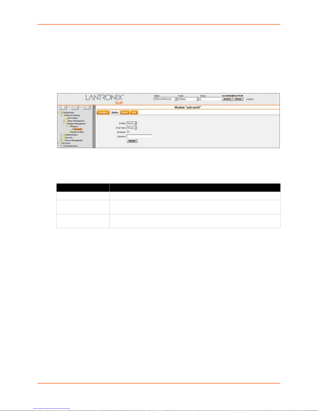
7: Network and Modem Settings
Enabling or Disabling Dial-in Connections
The system administrator can enable the modem to answer incoming calls and can set the mode
to use when establishing these connections.
To enable or disable dial-in connections to a modem:
1. Click the Dial in tab. The
following page opens:
Figure 7-34 Modem - Dial in Tab
2. Enter the following information:
Table 7-35 Modem - Dial-In Tab
Modem Setting Description
Profile From the drop-down list, select the desired profile. The default is none.
IPv4 Filter From the drop-down list, select an IPv4 filter for the connection. The default is
none.
Enabled Select this check box to allow incoming connections on this modem. Disabled
until a connection is selected.
3. To save, click the Submit butt
on. A confirmation message displays.
Viewing a List of Profiles
The administrator can view a list of modem connections.
1. On the menu, click Con
Profiles. The following page opens:
figuration > Network Settings > Modem Management > Modem
SLM User Guide 89
Page 90
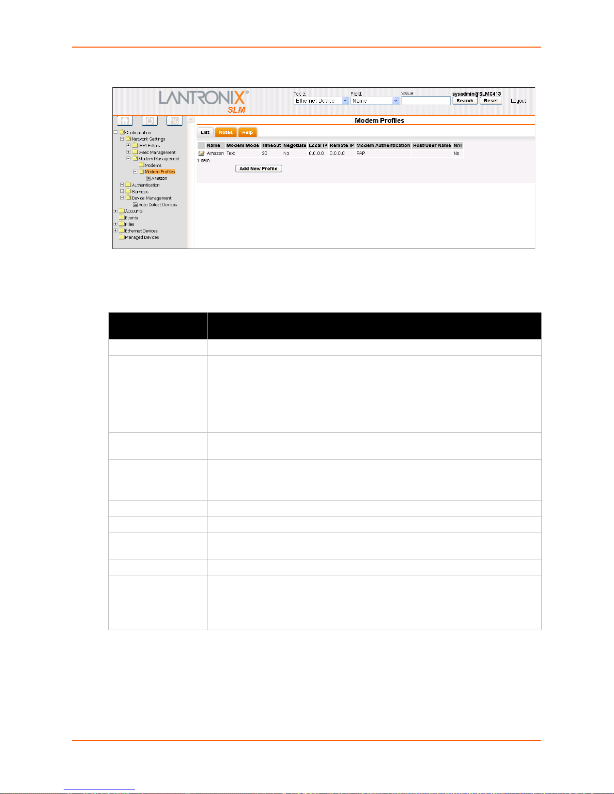
Figure 7-36 Modem Profiles - List Tab
2. View the following information about each connection:
Table 7-37 Modem Profile - List Tab
7: Network and Modem Settings
Modem Profiles
Setting
Name A name identifying the specific connection.
Modem Mode The format in which the data flows back and forth:
Timeout Indicates whether the connection times out logins after the connection is inactive
Negotiate If Yes, the remote device or PC specifies the local (SLM) IP and remote
Local IP IP address of the SLM.
Remote IP IP address of the remote device or remote PC.
Modem
Authentication
Host/User Name Username for dial-ins or dial-outs between the SLM and a remote system.
NAT If Yes, the SLM uses Network Address Translation (NAT) for dial-in PPP
Description
Text:
In this mode, the SLM assumes that the modem is for remotely logging into
the CLI. Text mode is only for dialing in.
PPP: T
his mode establishes an IP-based link over the modem. Dial-out mode uses
PPP connections (e.g., the SLM connects to an external network). You can dial out
from both the CLI and the web interface.
r a specified number of minutes (1-30).
fo
addresses.
If No, th
Indicates whether the SLM uses PAP or C
connections. Users dialing into the SLM access the network connected to Eth1
and/or Eth2.
e SLM assigns the local (SLM) IP and remote IP addresses.
HAP to authenticate modem logins.
Note: This does not apply to dial-out PPP.
Adding a Profile
The administrator can define a Text or PPP profile for use by an appropriate modem in the system.
To add a profile:
SLM User Guide 90
Page 91
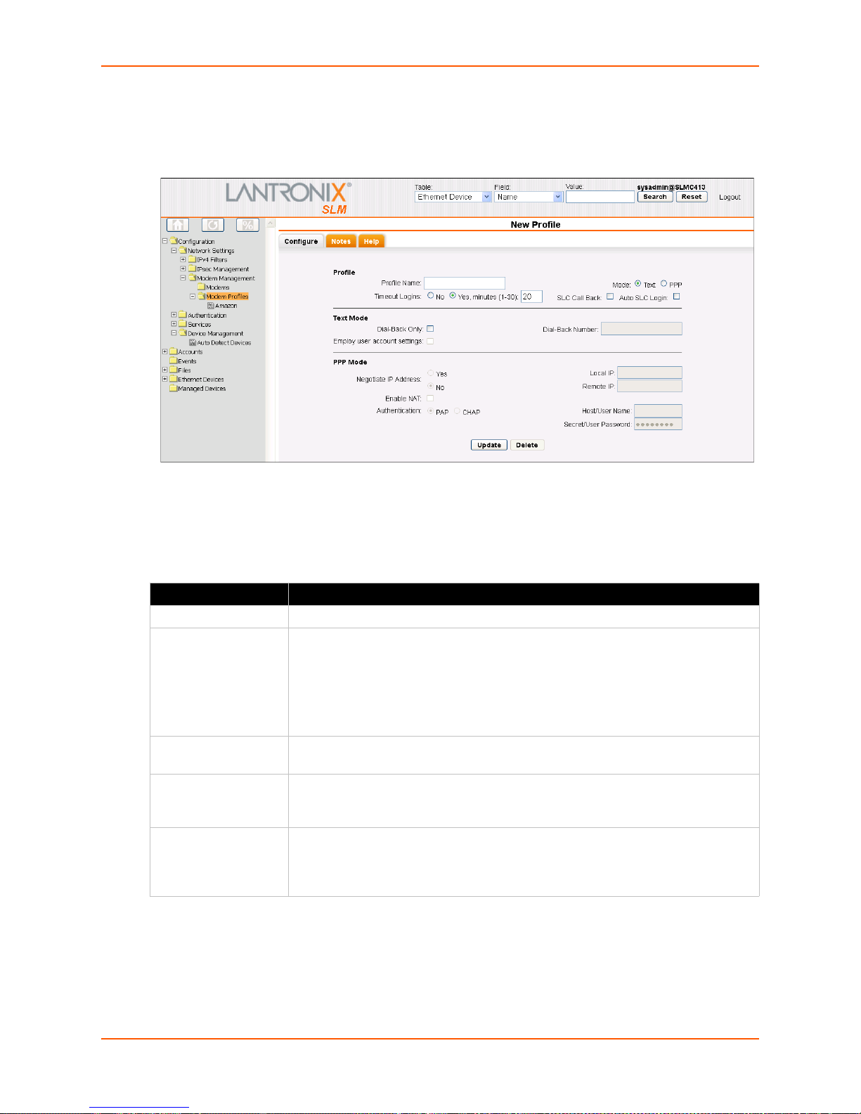
7: Network and Modem Settings
1. On the menu, click Configuration > Network Settings > Modem Management > Modem
Profiles, and then click the Add New Profile button. The following page opens:
Figure 7-38 New Profile-Configure Tab
2. Enter the following information:
Table 7-39 New Profile - Configure Tab - Profile
New Profile Setting Description
Profile Name A name identifying the specific profile.
Mode The format in which the data flows back and forth:
Text:
In this mode, the SLM assumes that the modem is for remotely logging into
the CLI. Text mode is only for dialing in. Enabled by default.
PPP: T
his mode establishes an IP-based link over the modem. Dial-out mode uses
PPP connections (e.g., the SLM connects to an external network). You can dial out
from both the CLI and the web interface.
Timeout Logins For both Text and PPP modes, you can enable logins to time out after the
nection is inactive for a specified number of minutes (1-30).
con
Call Back Select to enable this security feature. When the
the SLC hangs up and calls the user back. The SLM then logs in again. This
feature is currently available in text mode only.
Auto Login If you select the check box, when the SLM attempts to connect to an SLC via a text
mode
connection, it automatically uses the Login and Password specified on the
SLC Device page. If you do not select it, the user will have to enter the password
and login manually.
SLM user calls an SLC and logs in,
SLM User Guide 91
Page 92

7: Network and Modem Settings
Table 7-40 New Profile - Configure Tab - Text Mode
Text Mode Setting Description
Dial-Back Only Select to grant a local user dial-back access. Users with dial-back access can dial
into the SLM and enter their login and password. Once the SLM authenticates
them, the modem hangs up and dials them back. Disabled by default.
Following are the rules the SLM follows concerning Dial-Back
If both Dial-Bac
k Only and Use User Profile are not selected, users can dial in
text mode. (Regular usage).
If Dial-Back Only is not selected and Use User Profile is selected:
If Enable Dial-back is selected on the Manage Account page, the user can only
dial in using dial-back with the number defined on the Manage Account page.
If Enable Dial-back is not selected, the user can dial in using text mode.
If Dial-Back Only is selected and Use User Profile is not selected
dial in using dial-back. SLM dials back to the number defined on the Modem
Connection.
If Dial-Back Only is selected and Use User Profile is selected
If Enable Dial-back on the Manage account page is selected, the user can only
dial in using dial-back with the number defined on the Manage account page.
If Enable Dial-back on the Manage account page is not selected, the user can
only dial in using dial-back. SLM dials back to the number defined on the Modem
connection page.
Dial-Back Number Enter the phone number the modem dials back on. It can be a fixed number or a
mber associated with the user's login. If you select Fixed Number, enter the
nu
number in the format 2123456789.
Employ User Account
Settings
Select to indicate that the SLM takes dial-back rules from the local user account on
the Manage Account page (see Accounts on page 125).
Only in Text mode.
, users can only
Table 7-41 New Profile - Configur
e Tab - PPP Mode
PPP Mode Setting Description
Negotiate IP Address For the remote device or PC to specify the local (SLM) IP and remote addresses,
select Yes. Defaults to Yes.
For the SLM to assign the local (SLM) IP and remote IP addresses, select No, and
enter the local IP (IP address of the SLM) and remote IP (IP address of the remote
device or PC).
Local IP IP address of the SLM.
Remote IP IP address of the remote device or remote PC.
Enable NAT Select to enable Network Address Translation (NAT) for dial-in PPP connections.
Users dialing
into the SLM access the network connected to Eth1 and/or Eth2.
Note: This does not apply to dial-out PPP.
Authentication Enables PAP or C
With PAP, if you do not specify username and password, users are authenticated
HAP authentication for modem logins. PAP is the default.
by means of the Local Users and any of the remote authentication methods that
are enabled.
With CHAP, the CHAP Handshake fields authenticate the user. You must specify
the username and password.
Host/User Name User name for dial-ins or dial-outs between the SLM and a remote system for PAP
or CHAP authentication.
SLM User Guide 92
Page 93
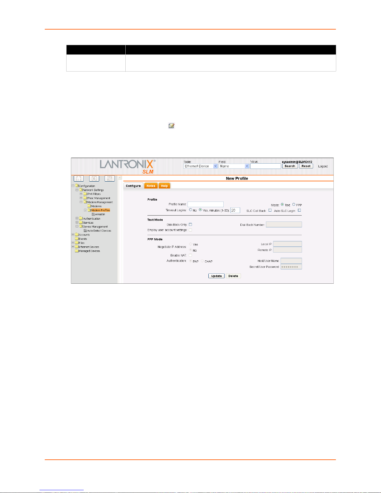
PPP Mode Setting Description
Secret/User
Password
Password for dial-ins or dial-outs between the SLM and a remote system for PAP or
CHAP authentication.
Updating and Deleting a Profile
The administrator can update or delete profiles.
To update or delete a modem profile:
7: Network and Modem Settings
1. On the menu, click Con
figuration > Network Settings > Modem Management > Modem
Profiles, and then click the Edit icon to the left of the modem profile you want to update or
delete. The Configure tab displays.
Figure 7-42 Modem Profile Page - Configure Tab
2. To delete a profile:
a. Click the Delete bu
tton.
b. In response to the request for confirmation, click OK.
c. Click M
odem Profiles on the menu tree. The deleted connection is no longer on the menu
tree or listed on the List tab.
3. To update a profile:
a. Edit the information as desired.
b. Click the Upda
Note: Fo
r information about configuring a dial-out profil, see Configuring a Modem
te button. A confirmation message displays.
Connection to a Managed Device on page 206.
Discovering a USB Modem
The system administrator can attach a USB modem to an SLM and configure it into the system
without rebooting the SLM. For the vSLM, a USB modem must first be connected to the vSLM VM
SLM User Guide 93
Page 94

7: Network and Modem Settings
prior to discovery of the modem; refer to the documentation for your virtualization manager for
instructions on connecting a USB device to a VM.
To "discover" a USB Modem:
1. On the menu, click Con
and then click the Discover tab. The Discover tab displays.
2. Click the Disco
modems) has started.
3. After a few moments, refresh the tree structure.
Modem Commands
reset modem connection
Note: You
minimum timeout period (3 minutes) before you use this command when:
You dial out via PPP and encounter no dial tone.
You dial out via PPP and encounter a busy signal.
Syntax
reset modem connection
Description
Resets a modem connection.
may only use this command when the modem is completely stuck. Wait for
figuration > Network Settings > Modem Management > Modems
ver button. A message displays indicating that the task (discovering USB
Any new USB modems display in the tree.
set modem disconnect
Note: Type
show modem to view the current modem connections.
Syntax
set modem disconnect <Name>
Example
set modem disconnect MyPCIModem
Description
Terminates modem dial-out connection.
set modem edit
Syntax
set modem edit <Modem Name> <parameters>
Parameters
name <New Name>
baud <300-115200>
flowcontrol <none|xon/xoff|rts/cts>
initscript <Modem Initialization Script>
defaultinitscript <Modem Default Initialization Script>
dialin <Dial Account Name|CLEAR|disable|enable>
SLM User Guide 94
Page 95

CLEAR removes the dial account assignment.
7: Network and Modem Settings
disable d
enable e
ipfilter <IPv4 Filter Name|CLEAR>
ipfilter
Description
Configures a currently loaded modem.
show modem
Syntax
show modem
Description
Displays all modems.
show modem connection
Syntax
show modem connection <parameters>
Parameters
[index <number>]
Description
isables dial-in.
nables dial-in
CLEAR removes the ipfilter assignment.
Displays active (established) modem connections.
show modem settings
Syntax
show modem <parameters>
Parameters
[name <Modem Name>]
[index <number>]
Description
Displays modem settings.
show modem status
Syntax
show modem status
Description
Displays the status of the modem.
Dial Account Commands
set dialaccount add
Syntax
SLM User Guide 95
Page 96

7: Network and Modem Settings
set dialaccount add <Dial Account Name> <parameters>
Parameters
modemmode <text|ppp>
If you select text, all other parameters except timeout are ignored.
localipaddr <negotiate|IP Address>
remoteipaddr <negotiate|IP Address>
auth <pap|chap>
username <User Name>
password <Password>
nat <enable|disable>
Default is 20.
Description
Creates a new dial account.
set dialaccount delete
Syntax
set dialaccount delete <Dial Account Name>
Description
Delete a dial account.
set dialaccount edit
Syntax
set dialaccount edit <Dial Account Name> <parameters>
Parameters
modemmode <text|ppp>
localipaddr <negotiate|IP Address>
remoteipaddr <negotiate|IP Address>
auth <pap|chap>
username <User Name>
password <Password>
nat <enable|disable>
forcedialback <disable|enable> (a
pply only text mode)
dialbacknumber <dial-back number|CLEAR> (apply only text mode)
CLEAR removes the dial-back number.
userprofile <disable|enable> (a
pply only text mode)
Uses local user-defined dial-back configuration.
timeout <disable|1-30 minutes>
Description
Modifies a dial account's settings.
set manageddevice config
SLM User Guide 96
Page 97

7: Network and Modem Settings
Syntax
set manageddevice config <Device Name> [dialout <Dial Account
Name|en
able|disable> modem <Modem Name> phonenumber
<phonenumber>]application <ssh|telnet|http|none>]
Description
Configures modem and dial account settings for a managed device.
set manageddevice index
Note: Type
show manageddevice all to display index.
Syntax
set manageddevice index <number> [dialout <Dial Account
Name|en
able|disable> modem <Modem Name> phonenumber
<phonenumber>]application ssh|telnet|http|none>]
Description
Finds managed device by index and modifies dial account settings.
To set modem parameters, you must specify a dial-out option.
set modem edit
Syntax
set modem edit <Modem Name> dialin <Dial Account
Name|CL
EAR|disable|enable>
Description
Modifies a dial-in account name.
show dialaccount
Note: Type
show dialaccount to display index.
Syntax
show dialaccount <parameters>
Parameters
[name <Dial Account Name>]
[index <number>]
Examples
show dialaccount
show dialaccount name ppp-pap
show dialaccount index 2
Description
Displays dial account settings.
show dialaccount mapping
SLM User Guide 97
Page 98

Syntax
show dialaccount mapping
Description
7: Network and Modem Settings
Shows dial account used b
y dial-in and dial-out.
SLM User Guide 98
Page 99

8: User Management
This chapter is primarily for administrators, who configure authentication methods, add, update,
and delete accounts and account groups, and grant account and account group permissions.
By default, local authentication is enabled and is
users. The administrator can select additional authentication methods, such as NIS, LDAP,
RADIUS, SecurID, and SSH public key or CLI login. The ability to assign different degrees of
access to individual users or user groups provides another level of security.
User Authentication Methods
On this page you may enable, disable and order methods for authenticating users attempting to
log in to the SLM. The methods include NIS, LDAP, RADIUS, Kerberos, TACACS+, SecurID, and
Local. The authentication method selection on the SLM does not affect devices or SLM interaction
with devices.
By default, local authentication is enabled and is
users. The ability to assign different degrees of access to individual users or user groups provides
another level of security.
The authentication method selection on the SLM doe
with devices.
Note: Fo
account must be configured for remote access (Remote Only or Local & Remote), or there
must be an account defined whose login name is th e same a s th e p roto col ( e.g., "NIS" for
NIS).
r a user to be authenticated using one of the remote methods, the user's
the first method the SLM uses to authenticate
the first method the SLM uses to authenticate
s not affect devices or SLM interaction
If you enable multiple authentication methods, the SLM
specified. When Attempt next method on authentication rejection is enabled, login authentication
continues until a configured method reports success or all configured methods have been
exhausted. When Attempt next method on authentication rejection is disabled, login authentication
continues until a configured method reports success or failure, skipping non-responding methods.
Note: Addi
undefined behavior. For this reason, the SLM prevents the addition of such accounts
when NIS is configured and enabled, but it is unable to stop the creation of such accounts
when NIS is disabled. The other remote authentication types are not affected by this
issue.
ng an NIS user with the same user name as a local user may result in
attempts login authentication in the order
SLM User Guide 99
Page 100
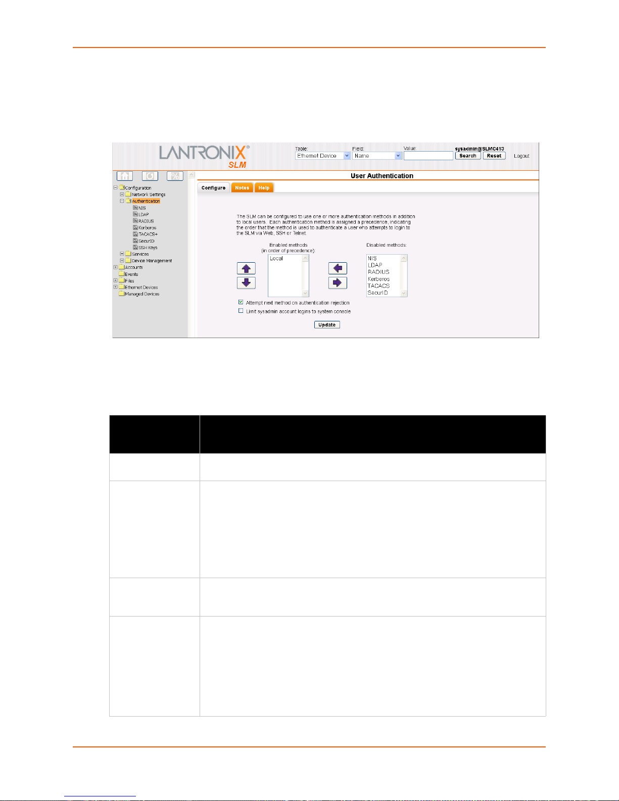
To enable, disable, and set the precedence of authentication methods:
8: User Management
1. On the menu, click Con
figuration > Authentication. The following page opens:
Figure 8-1 User Authentication - Configure Tab
2. To enable a method currently in the Disabled methods list, select the method and click the left
arrow.
Table 8-2 User Authentication - Configure Tab
User
Authentication
Setting
Local The SLM authenticates users in the local database by user name and password. If
NIS (Network
Information
System)
LDAP (Lightweight
Dire
ctory Access
Protocol)
RADIUS (Remote
Authentication
Dial-In User
Service)
Description
this method is enabled, it always responds.
A network naming and administration system developed by Sun Microsystems for
smaller networks. Each host client or server computer in the system has knowledge
about the entire system. A user at any host can access files or applications on any
host in the network with a single user name and password.
NIS uses the client/server model and the Remote Proced
communication between hosts. NIS consists of a server, a library of client programs,
and some administrative tools. NIS is often used with the Network File System
(NFS).
A set of protocols for accessing information directories, specifically X.500-based
directory services. LDAP runs over TCP/IP or other connection-oriented transfer
services.
An authentication and accounting system used by many Internet Service Providers
(ISPs). This client/server protocol enables remote access servers to authenticate
dial-in users and authorize their access to the requested system or service.
RADIUS allows a company to maintain user pro
remote servers can share. It increases security, allowing a company to set up a
policy that can be applied at a single administered network point.
Select RADIUS if a RADIUS server is used as a proxy for SecurID. Select SecurID if
a native SecurID server is used.
files in a central database that all
ure Call (RPC) interface for
SLM User Guide 100
 Loading...