

Page 1
SLC™ 8000
Advanced Console Manager
User Guide
Part Number 900-704-R
Revision B October 2014
Page 2

Copyright & Trademark
© 2014 Lantronix, Inc. All rights reserved. No part of the contents of this book may be transmitted
or reproduced in any form or by any means without the written permission of Lantronix.
Lantronix and Lantronix Spider are registered trademarks of Lantronix, Inc. in the United States
and other countries. SLC, SLP, and vSLM are trademarks of Lantronix, Inc.
Windows and Internet Explorer are registered trademarks of Microsoft Corporation. Firefox is a
registered trademark of the Mozilla Foundation. Chrome and iGoogle are trademarks of Google
Inc. All other trademarks and trade names are the property of their respective holders.
Warranty
For details on the Lantronix warranty policy, please go to our web site at
http://www.lantronix.com/support/warranty
Open Source Software
Some applications are Open Source software licensed under the Berkeley Software Distribution
(BSD) license or the GNU General Public License (GPL) as published by the Free Software
Foundation (FSF). Lantronix grants you no right to receive source code to the Open Source
software; however, in some cases, rights and access to source code for certain Open Source
software may be available directly from Lantronix’ licensors. Upon request, Lantronix will identify
the Open Source components and the licenses that apply to them. Your use of each Open Source
component or software is subject to the terms of the applicable license. The BSD license is
available at http://opensource.org/licenses. The GNU General Public License is available at
http://www.gnu.org/licenses/
the terms of the applicable license.
.
. Your use of each Open Source component or software is subject to
OPEN SOURCE SOFTWARE IS DISTRIBUTED WITHOUT ANY WARRANTY, INCLUDING ANY
IMPLIED WARRANTY OF MERCHANTABILITY OR FITNESS FOR A PARTICULAR PURPOSE.
SEE THE APPLICATION LICENSE AGREEMENT FOR ADDITIONAL INFORMATION.
Contacts
Lantronix Corporate Headquarters
167 Technology Drive
Irvine, CA 92618, USA
Toll Free: 800-526-8766
Phone: 949-453-3990
Fax: 949-453-3995
Technical Support
Online: www.lantronix.com/support
Sales Offices
For a current list of our domestic and international sales offices, go to the Lantronix web site at
www.lantronix.com/about/contact
.
SLC™ 8000 Advanced Console Manager User Guide 2
Page 3

Disclaimer & Revisions
All information contained herein is provided “AS IS.” Lantronix undertakes no obligation to update
the information in this publication. Lantronix does not make, and specifically disclaims, all
warranties of any kind (express, implied or otherwise) regarding title, non-infringement, fitness,
quality, accuracy, completeness, usefulness, suitability or performance of the information provided
herein. Lantronix shall have no liability whatsoever to any user for any damages, losses and
causes of action (whether in contract or in tort or otherwise) in connection with the user’s access or
usage of any of the information or content contained herein. The information and specifications
contained in this document are subject to change without notice.
Operation of this equipment in a residential area is likely to cause interference, in which case the
user, at his or her own expense, will be required to take whatever measures may be required to
correct the interference.
Note: This equipment has been tested and found to comply with the limits for Class A
digital device pursuant to Part 15 of the FCC Rules. These limits are designed to provide
reasonable protection against harmful interference when the equipment is operated in a
commercial environment. This equipment generates, uses, and can radiate radio
frequency energy and, if not installed and used in accordance with this User Guide, may
cause interference to radio communications. Operation of this equipment in a residential
area is likely to cause interference, in which case the user will be required to correct the
interference at his own expense.
Changes or modifications made to this device that are not explicitly approved by Lantronix will void
the user's authority to operate this device.
Revision History
Date Rev. Comments
March 2014 A Preliminary release.
October 2014 B Initial document for firmware release 7.1.0.0.
SLC™ 8000 Advanced Console Manager User Guide 3
Page 4

Table of Contents
Copyright & Trademark ______________________________________________________2
Warranty _________________________________________________________________2
Open Source Software ______________________________________________________2
Contacts _________________________________________________________________2
Disclaimer & Revisions ______________________________________________________3
Revision History ___________________________________________________________3
List of Tables ____________________________________________________________13
List of Figures ____________________________________________________________14
1: About this Guide 17
Purpose and Audience _____________________________________________________17
Summary of Chapters ______________________________________________________17
Additional Documentation ___________________________________________________18
2: Introduction 19
Features ________________________________________________________________19
Console Management __________________________________________________19
Power _______________________________________________________________19
Models __________________________________________________________________20
System Features __________________________________________________________20
Protocols Supported ____________________________________________________21
Access Control ________________________________________________________21
Device Port Buffer _____________________________________________________22
Configuration Options ___________________________________________________22
Hardware Features ________________________________________________________22
Serial Port Interfaces ___________________________________________________23
Network Connections ___________________________________________________24
USB Interface _________________________________________________________25
Memory Card Port _____________________________________________________25
Internal Modem ________________________________________________________26
3: Installation 27
What's in the Box _________________________________________________________27
Product Information Label _______________________________________________27
Technical Specifications ____________________________________________________28
Physical Installation ________________________________________________________29
Connecting to a Device Port ______________________________________________29
Modular Expansion for I/O Module _________________________________________31
Connecting to Network Ports _____________________________________________31
SLC™ 8000 Advanced Console Manager User Guide 4
Page 5

Connecting Terminals ___________________________________________________31
AC Input _____________________________________________________________32
Modem Installation _____________________________________________________33
Battery Replacement ___________________________________________________35
4: Quick Setup 39
Recommendations ________________________________________________________39
IP Address _______________________________________________________________39
Method #1 Using the Front Panel Display _______________________________________40
Front Panel LCD Display and Keypads _____________________________________40
Navigating ____________________________________________________________40
Entering the Settings ___________________________________________________42
Restoring Factory Defaults _______________________________________________43
Method #2 Quick Setup on the Web Page ______________________________________43
Network Settings ______________________________________________________45
Date & Time Settings ___________________________________________________45
Administrator Settings __________________________________________________46
Method #3 Quick Setup on the Command Line Interface ___________________________46
Next Step _______________________________________________________________49
5: Web and Command Line Interfaces 50
Web Manager ____________________________________________________________50
Logging in ____________________________________________________________52
Logging Out __________________________________________________________53
Web Page Help _______________________________________________________53
Command Line Interface ____________________________________________________53
Logging In ____________________________________________________________53
Logging Out __________________________________________________________54
Command Syntax ______________________________________________________54
Command Line Help ____________________________________________________54
Tips _________________________________________________________________54
General CLI Commands _________________________________________________55
6: Basic Parameters 57
Requirements ____________________________________________________________57
Ethernet Interfaces (Eth1 and Eth2) ________________________________________59
Gateway _____________________________________________________________60
Hostname & Name Servers ______________________________________________60
DNS Servers __________________________________________________________61
DHCP-Acquired DNS Servers ____________________________________________61
TCP Keepalive Parameters ______________________________________________61
Ethernet Counters _____________________________________________________61
SLC™ 8000 Advanced Console Manager User Guide 5
Page 6

Network Commands ____________________________________________________61
IP Filter _________________________________________________________________63
Viewing IP Filters ______________________________________________________63
Mapping Rulesets ______________________________________________________63
Enabling IP Filters _____________________________________________________64
Configuring IP Filters ___________________________________________________64
Rule Parameters _______________________________________________________65
Updating an IP Filter ____________________________________________________67
Deleting an IP Filter ____________________________________________________67
IP Filter Commands _______________________________________________________67
Routing _________________________________________________________________68
Dynamic Routing ______________________________________________________68
Static Routing _________________________________________________________69
Equivalent Routing Commands ___________________________________________69
VPN ____________________________________________________________________69
Configuring an IPsec VPN Tunnel through the CLI ________________________________72
Security _________________________________________________________________73
7: Services 75
System Logging and Other Services ___________________________________________75
SSH/Telnet/Logging _______________________________________________________76
System Logging _______________________________________________________76
Audit Log ____________________________________________________________77
SMTP _______________________________________________________________77
SSH ________________________________________________________________77
Telnet _______________________________________________________________78
Web SSH/Web Telnet Settings ___________________________________________78
Phone Home __________________________________________________________78
SNMP __________________________________________________________________78
Communities __________________________________________________________80
Version 3 ____________________________________________________________80
V3 Read-Only User ____________________________________________________81
V3 Read-Write User ____________________________________________________81
SNMP, SSH, Telnet, and Logging Commands ________________________________81
NFS and SMB/CIFS _______________________________________________________82
SMB/CIFS Share ______________________________________________________83
NFS and SMB/CIFS Commands __________________________________________84
Secure Lantronix Network ___________________________________________________85
Secure Lantronix Network Commands ______________________________________89
Date and Time ____________________________________________________________90
Date and Time Commands _______________________________________________92
Web Server ______________________________________________________________93
Admin Web Commands _________________________________________________94
SLC™ 8000 Advanced Console Manager User Guide 6
Page 7

Services - Web Sessions ________________________________________________95
Services - SSL Certificate ________________________________________________96
Web Server Commands _________________________________________________98
iGoogle Gadgets __________________________________________________________98
8: Device Ports 100
Connection Methods ______________________________________________________100
Permissions _____________________________________________________________100
I/O Modules _____________________________________________________________101
Device Status ___________________________________________________________102
Device Ports ____________________________________________________________103
Telnet/SSH/TCP in Port Numbers ________________________________________104
Global Commands ____________________________________________________104
Device Ports - Settings ____________________________________________________105
Device Port Settings ___________________________________________________107
IP Settings __________________________________________________________107
Data Settings ________________________________________________________108
Hardware Signal Triggers _______________________________________________109
Modem Settings (Device Ports) __________________________________________109
Modem Settings: Text Mode _____________________________________________110
Modem Settings: PPP Mode ____________________________________________110
Port Status and Counters _______________________________________________112
Device Ports - SLP / ServerTech CDU Device _______________________________112
Status/Info __________________________________________________________114
Commands __________________________________________________________114
Device Port - Sensorsoft Device __________________________________________114
Device Port Commands ________________________________________________115
Device Commands ____________________________________________________117
Interacting with a Device Port _______________________________________________118
Device Ports - Logging ____________________________________________________119
Local Logging ________________________________________________________119
NFS File Logging _____________________________________________________119
USB and SD Card Logging ______________________________________________120
Email/SNMP Notification _______________________________________________120
Sylog Logging ________________________________________________________120
Local Logging ________________________________________________________121
Email/Traps _________________________________________________________121
Log Viewing Attributes _________________________________________________123
NFS File Logging _____________________________________________________123
USB / SD Card Logging ________________________________________________123
Syslog Logging _______________________________________________________123
Logging Commands ___________________________________________________124
Console Port ____________________________________________________________125
SLC™ 8000 Advanced Console Manager User Guide 7
Page 8

Console Port Commands _______________________________________________126
Internal Modem Settings ___________________________________________________126
Setting Up Internal Modem Storage _______________________________________127
Host Lists ______________________________________________________________130
Host Parameters ______________________________________________________131
Host Parameters ______________________________________________________133
Host List Commands __________________________________________________134
Scripts _________________________________________________________________135
Scripts ______________________________________________________________137
User Rights __________________________________________________________138
Batch Script Syntax ___________________________________________________139
Interface Script Syntax _________________________________________________140
Primary Commands ___________________________________________________141
Secondary Commands _________________________________________________142
Control Flow Commands _______________________________________________144
Sample Scripts _______________________________________________________145
Batch Script—SLC CLI _________________________________________________147
Sites __________________________________________________________________149
Modem Dialing States _____________________________________________________152
Dial In ______________________________________________________________152
Dial-back ____________________________________________________________153
Dial-on-demand ______________________________________________________153
Dial-in & Dial-on-demand _______________________________________________154
Dial-back & Dial-on-demand _____________________________________________154
CBCP Server ________________________________________________________155
9: USB/SD Card Port 157
Set Up of USB/SD Card Storage ____________________________________________157
Data Settings ________________________________________________________161
Modem Settings ______________________________________________________161
Text Mode ___________________________________________________________162
PPP Mode __________________________________________________________163
IP Settings __________________________________________________________164
Manage Files ____________________________________________________________164
USB Commands _________________________________________________________165
SD Card Commands ______________________________________________________165
10: Connections 166
Typical Setup Scenarios for the SLC Unit ______________________________________166
Terminal Server ______________________________________________________166
Remote Access Server _________________________________________________167
Reverse Terminal Server _______________________________________________167
Multiport Device Server ________________________________________________168
SLC™ 8000 Advanced Console Manager User Guide 8
Page 9

Console Server _______________________________________________________168
Connection Configuration _______________________________________________169
Connection Commands ________________________________________________171
11: User Authentication 174
Authentication Commands ______________________________________________176
User Rights _____________________________________________________________177
Local and Remote User Settings ____________________________________________178
Adding, Editing or Deleting a User ________________________________________179
Shortcut ____________________________________________________________183
Local Users Commands ________________________________________________183
Local User Rights Commands ___________________________________________184
Remote User Commands _______________________________________________185
Parameters __________________________________________________________185
NIS ___________________________________________________________________186
NIS Commands ______________________________________________________189
LDAP __________________________________________________________________190
LDAP Commands _____________________________________________________194
RADIUS ________________________________________________________________196
RADIUS Commands ___________________________________________________199
User Attributes & Permissions from LDAP Schema or RADIUS VSA _____________ 200
Kerberos _______________________________________________________________201
Kerberos Commands __________________________________________________204
TACACS+ ______________________________________________________________205
TACACS+ Commands _________________________________________________208
Groups ________________________________________________________________209
SSH Keys ______________________________________________________________212
Imported Keys _______________________________________________________212
Exported Keys _______________________________________________________213
Imported Keys (SSH In) ________________________________________________215
Host & Login for Import _________________________________________________215
Exported Keys (SSH Out) _______________________________________________215
Host and Login for Export _______________________________________________216
SSH Commands ______________________________________________________218
Custom Menus __________________________________________________________220
Custom User Menu Commands __________________________________________223
12: Maintenance 227
Firmware & Configurations _________________________________________________227
Internal Temperature __________________________________________________229
Site Information ______________________________________________________229
SLC Firmware ________________________________________________________229
Boot Banks __________________________________________________________230
SLC™ 8000 Advanced Console Manager User Guide 9
Page 10

Load Firmware Via Options _____________________________________________230
Configuration Management _____________________________________________231
Manage Files ________________________________________________________232
Administrative Commands ______________________________________________232
System Logs _________________________________________________________235
System Log Command _________________________________________________236
Audit Log _______________________________________________________________237
Email Log ______________________________________________________________239
Diagnostics _____________________________________________________________240
Diagnostic Commands _________________________________________________241
Status/Reports __________________________________________________________244
View Report _________________________________________________________245
Status Commands ____________________________________________________246
Emailing Logs and Reports _________________________________________________246
Events _________________________________________________________________249
Events Commands ____________________________________________________250
LCD/Keypad ____________________________________________________________251
LCD/Keypad Commands _______________________________________________253
Banners ________________________________________________________________253
Banner Commands ____________________________________________________254
13: Application Examples 255
Telnet/SSH to a Remote Device __________________________________________255
Dial-in (Text Mode) to a Remote Device _______________________________________257
Local Serial Connection to Network Device via Telnet ____________________________258
14: Command Reference 260
Introduction to Commands _________________________________________________260
Command Syntax _____________________________________________________260
Command Line Help ___________________________________________________261
Tips ________________________________________________________________261
Administrative Commands _________________________________________________262
Audit Log Commands _____________________________________________________271
Authentication Commands _________________________________________________272
Kerberos Commands _____________________________________________________273
LDAP Commands ________________________________________________________274
Local Users Commands ___________________________________________________275
NIS Commands __________________________________________________________278
RADIUS Commands ______________________________________________________279
TACACS+ Commands ____________________________________________________280
User Permissions Commands _______________________________________________281
CLI Commands __________________________________________________________284
Connection Commands ____________________________________________________285
SLC™ 8000 Advanced Console Manager User Guide 10
Page 11

Custom User Menu Commands _____________________________________________289
Date and Time Commands _________________________________________________291
Device Commands _______________________________________________________292
Device Port Commands ___________________________________________________293
Diagnostic Commands ____________________________________________________297
End Device Commands ___________________________________________________300
Events Commands _______________________________________________________301
Group Commands ________________________________________________________302
Host List Commands ______________________________________________________303
Internal Modem Commands ________________________________________________305
IP Filter Commands ______________________________________________________305
Logging Commands ______________________________________________________306
Network Commands ______________________________________________________309
NFS and SMB/CIFS Commands _____________________________________________312
Routing Commands ______________________________________________________313
SD Card Commands ______________________________________________________314
Security Commands ______________________________________________________315
Services Commands ______________________________________________________315
SLC Network Commands __________________________________________________317
SSH Key Commands ____________________________________________________317
Status Commands ________________________________________________________320
System Log Commands ___________________________________________________321
USB Access Commands ___________________________________________________322
USB Storage Commands __________________________________________________322
USB Modem Commands __________________________________________________324
VPN Commands _________________________________________________________325
Appendix A: Security Considerations 328
Security Practice _________________________________________________________328
Factors Affecting Security __________________________________________________328
Appendix B: Safety Information 329
Safety Precautions _______________________________________________________329
Cover ______________________________________________________________329
Power Plug __________________________________________________________329
Input Supply _________________________________________________________329
Grounding ___________________________________________________________329
Fuses ______________________________________________________________329
Rack _______________________________________________________________330
Port Connections _____________________________________________________330
SLC™ 8000 Advanced Console Manager User Guide 11
Page 12

Appendix C: Adapters and Pinouts 331
Appendix D: Protocol Glossary 334
Appendix E: Compliance Information 336
SLC™ 8000 Advanced Console Manager User Guide 12
Page 13

List of Tables
Table 2-5 Console (DTE) Port Pinout ________________________________________________23
Table 3-1 Part Numbers and Descriptions _____________________________________________27
Table 3-2 SLC Technical Specifications ______________________________________________28
Table 3-4 Console Port and Device Port (DTE) - Reverse Pinout Disabled ___________________30
Table 3-5 Device Port (DCE) - Reverse Pinout Enabled __________________________________30
Table 3-6 Available I/O Configurations _______________________________________________31
Table 4-1 Methods of Assigning an IP Address _________________________________________39
Table 4-3 LCD Arrow Keypad Actions ________________________________________________41
Table 4-4 Front Panel Setup Options with Associated Parameters __________________________41
Table 5-2 CLI Keyboard Shortcuts ___________________________________________________56
Table 8-1 Supported I/O Module Configurations _______________________________________101
Table 8-6 Port Status and Counters _________________________________________________112
Table 8-16 Definitions ___________________________________________________________140
Table 8-17 Primary Commands ____________________________________________________141
Table 8-18 Secondary Commands _________________________________________________143
Table 8-19 Control Flow Commands ________________________________________________144
Table 11-2 User Types and Rights _________________________________________________177
Table 14-1 Actions and Category Options ___________________________________________260
SLC™ 8000 Advanced Console Manager User Guide 13
Page 14

List of Figures
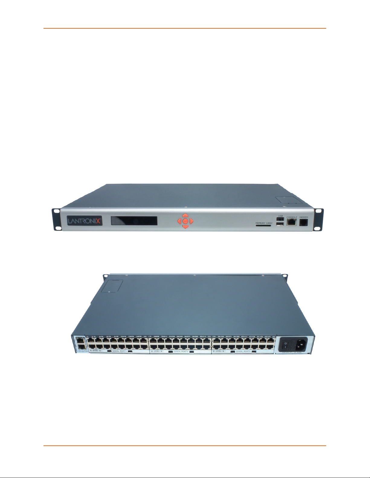
Figure 2-1 SLC 8048 Unit (Front Side) - Part Number SLC 804812N-01-S ____________________20
Figure 2-2 SLC 8048 Unit (Back Side) - Part Number SLC 804812N-01-S ____________________20
Figure 2-3 Device Ports (Back Side) _________________________________________________23
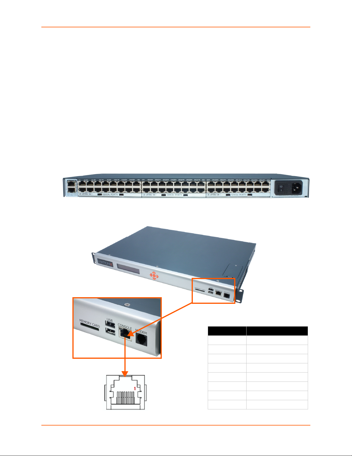
Figure 2-4 Console Port (Front Side) _________________________________________________23
Figure 2-6 Network Connection _____________________________________________________24
Figure 2-7 Dual USB Ports _________________________________________________________25
Figure 2-8 Memory Card Port _______________________________________________________25
Figure 2-9 Internal Modem Location __________________________________________________26
Figure 3-3 Device Port Connections (Back Side) ________________________________________30
Figure 3-7 AC Power Input _________________________________________________________32
Figure 4-2 Front Panel LCD Display and Five Button Keypad (Enter, Up, Down, Left, Right) ______40
Figure 4-5 Quick Setup ____________________________________________________________44
Figure 4-6 Home _________________________________________________________________44
Figure 4-7 Quick Setup Completed in Web Manager _____________________________________46
Figure 4-8 Beginning of Quick Setup Script ____________________________________________47
Figure 4-9 Quick Setup Completed in CLI _____________________________________________48
Figure 5-1 Web Page Layout _______________________________________________________51
Figure 6-1 Network > Network Settings _______________________________________________58
Figure 6-2 Network > IP Filter ______________________________________________________63
Figure 6-3 Network > IP Filter Ruleset (Adding/Editing Rulesets) ___________________________65
Figure 6-4 Network > Routing_______________________________________________________68
Figure 6-5 Network > VPN _________________________________________________________70
Figure 6-6 Network > Security ______________________________________________________74
Figure 7-1 Services > SSH/Telnet/Logging_____________________________________________76
Figure 7-2 Services > SNMP _______________________________________________________79
Figure 7-3 Services > NFS & SMB/CIFS ______________________________________________83
Figure 7-4 Services > Secure Lantronix Network ________________________________________86
Figure 7-5 IP Address Login Page ___________________________________________________87
Figure 7-6 SSH and Telnet Opening File Popups________________________________________87
Figure 7-7 SSH or Telnet CLI Session ________________________________________________88
Figure 7-8 Disabled Port Number Popup Window _______________________________________88
Figure 7-9 Services > Secure Lantronix Network > Search Options__________________________89
Figure 7-10 Services > Date & Time _________________________________________________91
Figure 7-11 Services > Web Server _________________________________________________93
Figure 7-12 Web Sessions _________________________________________________________96
SLC™ 8000 Advanced Console Manager User Guide 14
Page 15

Figure 7-13 SSL Certificate_________________________________________________________97
Figure 7-14 iGoogle Gadget Example_________________________________________________99
Figure 8-2 Devices > Device Status _________________________________________________102
Figure 8-3 Devices > Device Ports __________________________________________________103
Figure 8-4 Port Number Bar _______________________________________________________105
Figure 8-5 Device Ports > Settings __________________________________________________106
Figure 8-7 Device Ports > SLP / ServerTech CDU______________________________________113
Figure 8-8 Devices > Device Ports > Sensorsoft _______________________________________114
Figure 8-9 Devices > Device Ports - Logging __________________________________________121
Figure 8-10 Devices > Console Port _________________________________________________125
Figure 8-11 Devices > Internal Modem_______________________________________________128
Figure 8-12 Devices > Host Lists ___________________________________________________131
Figure 8-13 View Host Lists _______________________________________________________133
Figure 8-14 Devices > Scripts______________________________________________________136
Figure 8-15 Adding or Editing New Scripts ____________________________________________137
Figure 9-1 Devices > USB / SD Card ________________________________________________158
Figure 9-2 Devices > USB > Configure_______________________________________________158
Figure 9-3 Devices > SD Card > Configure ___________________________________________159
Figure 9-4 Devices > USB > Modem ________________________________________________160
Figure 9-5 Firmware and Configurations - Manage Files (Top of Page)______________________164
Figure 10-1 Terminal Server _______________________________________________________167
Figure 10-2 Remote Access Server _________________________________________________167
Figure 10-3 Reverse Terminal Server________________________________________________167
Figure 10-4 Multiport Device Server _________________________________________________168
Figure 10-5 Console Server _______________________________________________________168
Figure 10-6 Devices > Connections _________________________________________________169
Figure 10-7 Current Connections ___________________________________________________170
Figure 11-1 User Authentication > Authentication Methods _______________________________175
Figure 11-3 User Authentication > Local/Remote Users__________________________________178
Figure 11-4 User Authentication > Local/Remote User > Add/Edit User _____________________180
Figure 11-5 User Authentication > NIS _______________________________________________186
Figure 11-6 User Authentication > LDAP _____________________________________________191
Figure 11-7 User Authentication > RADIUS ___________________________________________196
Figure 11-8 User Authentication > Kerberos___________________________________________202
Figure 11-9 User Authentication > TACACS+__________________________________________206
Figure 11-10 User Authentication > Groups ___________________________________________210
Figure 11-11 User Authentication > SSH Keys_________________________________________214
Figure 11-12 Current Host Keys ___________________________________________________217
SLC™ 8000 Advanced Console Manager User Guide 15
Page 16

Figure 11-13 User Authentication > Custom Menus_____________________________________221
Figure 12-1 Maintenance > Firmware & Configurations __________________________________228
Figure 12-2 Network > Firmware/Config > Manage _____________________________________232
Figure 12-3 Maintenance > System Logs _____________________________________________235
Figure 12-4 System Logs _________________________________________________________236
Figure 12-5 Maintenance > Audit Log________________________________________________238
Figure 12-6 Maintenance > Email Log _______________________________________________239
Figure 12-7 Maintenance > Diagnostics ______________________________________________240
Figure 12-8 Diagnostics Report ____________________________________________________241
Figure 12-9 Maintenance > Status/Reports ___________________________________________244
Figure 12-10 Generated Status/Reports______________________________________________245
Figure 12-11 Emailed Log or Report_________________________________________________247
Figure 12-12 About SLC __________________________________________________________248
Figure 12-13 Maintenance > Events_________________________________________________249
Figure 12-14 Maintenance > LCD/Keypad ____________________________________________252
Figure 12-15 Maintenance > Banners________________________________________________253
Figure 13-1 SLC - Console Manager Configuration _____________________________________255
Figure 13-2 Remote User Connected to a SUN Server via the SLC unit _____________________255
Figure 13-3 Dial-in (Text Mode) to a Remote Device ____________________________________257
Figure 13-4 Local Serial Connection to Network Device via Telnet _________________________258
Figure C-1 RJ45. Receptacle to DB25M DCE Adapter for the SLC unit (PN 200.2066A) ________ 331
Figure C-2 RJ45 Receptacle to DB25F DCE Adapter for the SLC unit (PN 200.2067A) _________332
Figure C-3 RJ45 Receptacle to DB9M DCE Adapter for the SLC unit (PN 200.2069A)__________332
Figure C-4 RJ45 Receptacle to DB9F DCE Adapter for the SLC unit (PN 200.2070A) __________333
SLC™ 8000 Advanced Console Manager User Guide 16
Page 17

1: About this Guide
Purpose and Audience
This guide provides the information needed to install, configure, and use the Lantronix® SLC™
8000 Advanced Console Manager. The SLC unit is for IT professionals who must remotely and
securely configure and administer servers, routers, switches, telephone equipment, or other
devices equipped with a serial port for facilities that are typically remote branch offices or
“distributed” IT locations.
Summary of Chapters
The remaining chapters in this guide include:
Chapter Description
Chapter 2: Introduction Describes the SLC 8000 models, their main features, and the protocols they
support.
Chapter 3: Installation Provides technical specifications; describes connection formats and power
supplies; provides instructions for installing the SLC 8000 advanced console
manager in a rack.
Chapter 4: Quick Setup Provides instructions for getting your SLC unit up and running and for
configuring required settings.
Chapter 5: Web and
Command Line Interfaces
Chapter 6: Basic Parameters Provides instructions for configuring network ports, firewall and routing
Chapter 7: Services Provides instructions for enabling and disabling system logging, SSH and
Chapter 8: Device Ports Provides instructions for configuring global device port settings, individual
Chapter 9: USB/SD Card Port Provides instructions for using the USB port.
Chapter 10: Connections Provides instructions for configuring connections and viewing, updating, or
Chapter 11: User
Authentication
Chapter 12: Maintenance Provides instructions for upgrading firmware, viewing system logs and
Chapter 13: Application
Examples
Chapter 14: Command
Reference
Describes the web and command line interfaces available for configuring
the SLC 8000 advanced console manager.
The configuration chapters (6-12) provide detailed instructions for using the
web interface and include equivalent command line interface commands.
settings, and VPN.
Telnet logins, SNMP, SMTP, and the date and time.
device port settings, and console port settings.
disconnecting a connection.
Provides instructions for enabling or disabling methods that authenticate
users who attempt to log in via the web, SSH, Telnet, or the console port.
Provides instructions for creating custom menus.
diagnostics, generating reports, and defining events. Includes information
about web pages and commands used to shut down and reboot the SLC
8000 advanced console manager.
Shows how to set up and use the SLC unit in three different configurations.
Lists and describes all of the commands available on the SLC command line
interface
SLC™ 8000 Advanced Console Manager User Guide 17
Page 18

Chapter (continued) Description
Appendix A: Security
Considerations
Appendix B: Safety
Information
Appendix C: Adapters and
Pinouts
Appendix D: Protocol
Glossary
Appendix E: Compliance
Information
Provides tips for enhancing SLC security.
Lists safety precautions for using the SLC 8000 advanced console
manager.
Includes adapter pinout diagrams.
Lists the protocols supported by the SLC unit with brief descriptions.
Provides information about the SLC 8000 advanced console manager’s
compliance with industry standards.
Additional Documentation
Visit the Lantronix Web site at www.lantronix.com/support/documentation for the latest
documentation and the following additional documentation.
Document Description
SLC 8000 Advanced Console Manager
Quick Start
SLC 8000 Advanced Console Manager
Online Help for the Command Line
Reference
SLC 8000 Advanced Console Manager
Online Help for the Web Interface
1: About this Guide
Describes the steps for getting the SLC unit up and running.
Provides online help for configuring the SLC 8000
advanced console manager using commands.
Provides online help for configuring the SLC 8000
advanced console manager using the web page.
SLC™ 8000 Advanced Console Manager User Guide 18
Page 19

2: Introduction
The SLC 8000 advanced console manager enables IT system administrators to manage remote
servers and IT infrastructure equipment securely over the Internet.
IT equipment can be configured, administered, and managed in a variety of ways, but most
devices have one method in common: an RS-232 serial port, sometimes called a console,
auxiliary, or management port. These ports are often accessed directly by connecting a terminal or
laptop to them, meaning that the administrator must be in the same physical location as the
equipment. The SLC 8000 advanced console manager gives the administrator a way to access
them remotely from anywhere there is a network or modem connection.
Many types of equipment can be accessed and administered using console managers including:
Servers: Unix, Linux, Windows, and others.
Networking equipment: Routers, switches, storage networking.
Telecom: PBX, voice switches.
Other systems with serial interfaces: Heating/cooling systems, security/building access
systems, UPS, medial devices.
The key benefits of using console managers:
Saves money: Enables remote management and troubleshooting without sending a
technician onsite. Reduces travel costs and downtime costs.
Saves time: Provides instant access and reduces response time, improving efficiency.
Simplifies access: Enables you to access equipment securely and remotely after hours and
Protects assets: Security features provide encryption, authentication, authorization, and
Features
Console Management
Up to 48 RS-232 serial ports for console connectivity
Enables system administrators to remotely manage devices with serial console ports, e.g.,
Provides data logging, monitoring, and secure access control via the Internet
on weekends and holidays—without having to schedule visits or arrange for off-hour access.
firewall features to protect your IT infrastructure while providing flexible remote access.
The SLC advanced console manager provides features such as convenient text menu
systems, break-safe operation, port buffering (logging), remote authentication, and Secure
Shell (SSH) access. Dial-up modem support ensures access when the network is not
available.
Linux, Unix, and recent versions of Windows servers, routers, telecom, and switches with RS232C (now EIA-232) compatible serial consoles in a 1U-tall rack space. All models have two
Ethernet ports called Eth1 and Eth2 in this document.
Power
Universal AC power input (100-240V, 50/60 Hz)
Convection cooled, silent operation, low power consumption
SLC™ 8000 Advanced Console Manager User Guide 19
Page 20
Models
SLC 8048 has the following hardware components:
SLC Chassis: The SLC 8000 advanced console manager has a 1U tall, self-contained rack-
Serial Device Ports: Up to forty-eight serial RS-232C (EIA-232) device ports are for remote
Network Ports: The SLC unit has two 10/100/1000 Base-T Ethernet ports (referred to in this
Console Port: The SLC has a front panel serial console port (RJ45).
SLC 8000 advanced console manager also includes two USB type A ports in the front panel.
2: Introduction
mountable chassis.
console management of the attached equipment. These match the RJ45 pin-outs of the
console ports of many popular devices found in a network environment, and where different
can be converted using Lantronix adapters. See Appendix C: Adapters and Pinouts on page
331 for more information on serial adapters and pin-outs.
user guide as Eth1 and Eth2)
Figure 2-1 SLC 8048 Unit (Front Side) - Part Number SLC 804812N-01-S
Figure 2-2 SLC 8048 Unit (Back Side) - Part Number SLC 804812N-01-S
System Features
The SLC 8000 firmware has the following basic capabilities:
Software reversible device port pinouts
Connects up to 48 RS-232 serial consoles
SLC™ 8000 Advanced Console Manager User Guide 20
Page 21

2: Introduction
10/100/1000 Base-T Ethernet network compatibility
Buffer logging to file
Email and SNMP notification
ID/Password security, configurable access rights
Secure shell (SSH) security; supports numerous other security protocols
Network File System (NFS) and Common Internet File System (CIFS) support
RAW TCP, Telnet or SSH to a serial port by IP address per port or by IP address and TCP port
number
Configurable user rights for local and remotely authenticated users
Supports an external modem
No unintentional break ever sent to attached servers (Solaris Ready)
Simultaneous access on the same port - “listen” and “direct” connect mode
Local access through a console port
Web administration (using most browsers)
Protocols Supported
The SLC 8000 advanced console manager supports the TCP/IP network protocol as well as:
SSH, Telnet, PPP, NFS, and CIFS for connections in and out of the SLC console manager
SMTP for mail transfer
DNS for text-to-IP address name resolution
SNMP for remote monitoring and management
SCP, FTP and SFTP for file transfers and firmware upgrades
TFTP for firmware upgrades
DHCP and BOOTP for IP address assignment
HTTPS (SSL) for secure browser-based configuration
NTP for time synchronization
LDAP, NIS, RADIUS, CHAP, PAP, Kerberos, TACACS+, and SecurID (via RADIUS) for user
authentication
Callback Control Protocol (CBCP)
IPsec for VPN access
For brief descriptions of these protocols, see Appendix D: Protocol Glossary on page 334.
Access Control
The system administrator controls access to attached servers or devices by assigning access
rights to up to 128 user profiles. Each user has an assigned ID, password, and access rights.
Other user profile access options may include externally configured authentication methods such
as NIS and LDAP.
SLC™ 8000 Advanced Console Manager User Guide 21
Page 22

Device Port Buffer
The SLC 8000 unit supports real-time data logging for each device port. The port can save the
data log to a file, send an email notification of an issue, or take no action.
You can define the path for logged data on a port-by-port basis, configure file size and number of
files per port for each logging event, and configure the device log to send an email alert message
automatically to the appropriate parties indicating a particular error.
Configuration Options
You may use the backlit front-panel LCD display for initial setup and configuration and to view
current network, console, and date/time settings, and get internal temperature status.
Both a web interface viewed through a standard browser and a command line interface (CLI) are
available for configuring the SLC settings and monitoring performance.
Hardware Features
The SLC 8000 hardware includes the following:
1U-tall (1.75 inch) rack-mountable appliance
2: Introduction
Two 10/100/1000 Base-T network ports with LED for link and activity
Up to 48 RS-232 serial device ports connected via RJ45 wiring
One front panel serial console port for VT100 terminal or PC with emulation with LED for
activity indicators
Two USB Ports
Secure Digital (SD) memory card slot
Front panel LCD display and keypad
256 KB-per-port buffer memory for serial device ports
Software reversible device port pinouts
LCD display and keypad on the front
Universal AC power input (100-240V, 50/60 Hz)
Convection cooled, silent operation, low power consumption
Note: For more detailed information, see Chapter 4: Quick Setup on page 39.
SLC™ 8000 Advanced Console Manager User Guide 22
Page 23
2: Introduction
Table 2-5 Console (DTE) Port Pinout
Pin Number Description
1 RTS (output)
2 DTR (output)
3 TXD (output)
4 Ground
5 Ground
6 RXD (input)
7 DSR (input)
8 CTS (input)
Serial Port Interfaces
All devices attached to the device ports and the console port must support the RS-232C (EIA-232)
standard. RJ45 cabling, like Category 5 or 6 patch cabling, is used for the device port connections
and for the console port. (For pinout information, see the Appendix C: Adapters and Pinouts on
page 331.)
Device ports for the SLC 8000 advanced console manager are reversed by default so that straightthrough RJ45 patch cables may be used to connect to Cisco and Sun RJ45 serial console ports. If
you are replacing an SLC with an SLC 8000 you can either switch the ports to the non-reversed
pinout used by SLC units and use your original cables and adapters, or remove any rolled cables
or adapters and replace them with straight-through RJ45 cables, e.g. Ethernet patch cables.
Note: RJ45 to DB9/DB25 adapters are available from Lantronix.
Device ports and the console port support the following baud-rate options: 300, 600, 1200, 2400,
4800, 9600, 19200, 38400, 57600, 115200 and 230400 baud.
Figure 2-3 Device Ports (Back Side)
Figure 2-4 Console Port (Front Side)
SLC™ 8000 Advanced Console Manager User Guide 23
Page 24
2: Introduction
Network Connections
The SLC 8000 network interfaces are 10/100/1000 Base-T Ethernet for use with a conventional
Ethernet network as shown in Figure 2-6. Use standard RJ45-terminated cables, like Category 5 or
6 patch cable. Additionally, CAT5E or better cables are recommended for 1000 Base Ethernet.
Network parameters must be configured before the SLC console manager can be accessed over the
network.
Note: One possible use for the two Ethernet ports is to have one port on a private,
secure network and the other on a public, unsecured network.
Figure 2-6 Network Connection
SLC™ 8000 Advanced Console Manager User Guide 24
Page 25
USB Interface
The SLC 8000 unit has two 2.0 USB ports (HS, FS, LS).
Figure 2-7 Dual USB Ports
2: Introduction
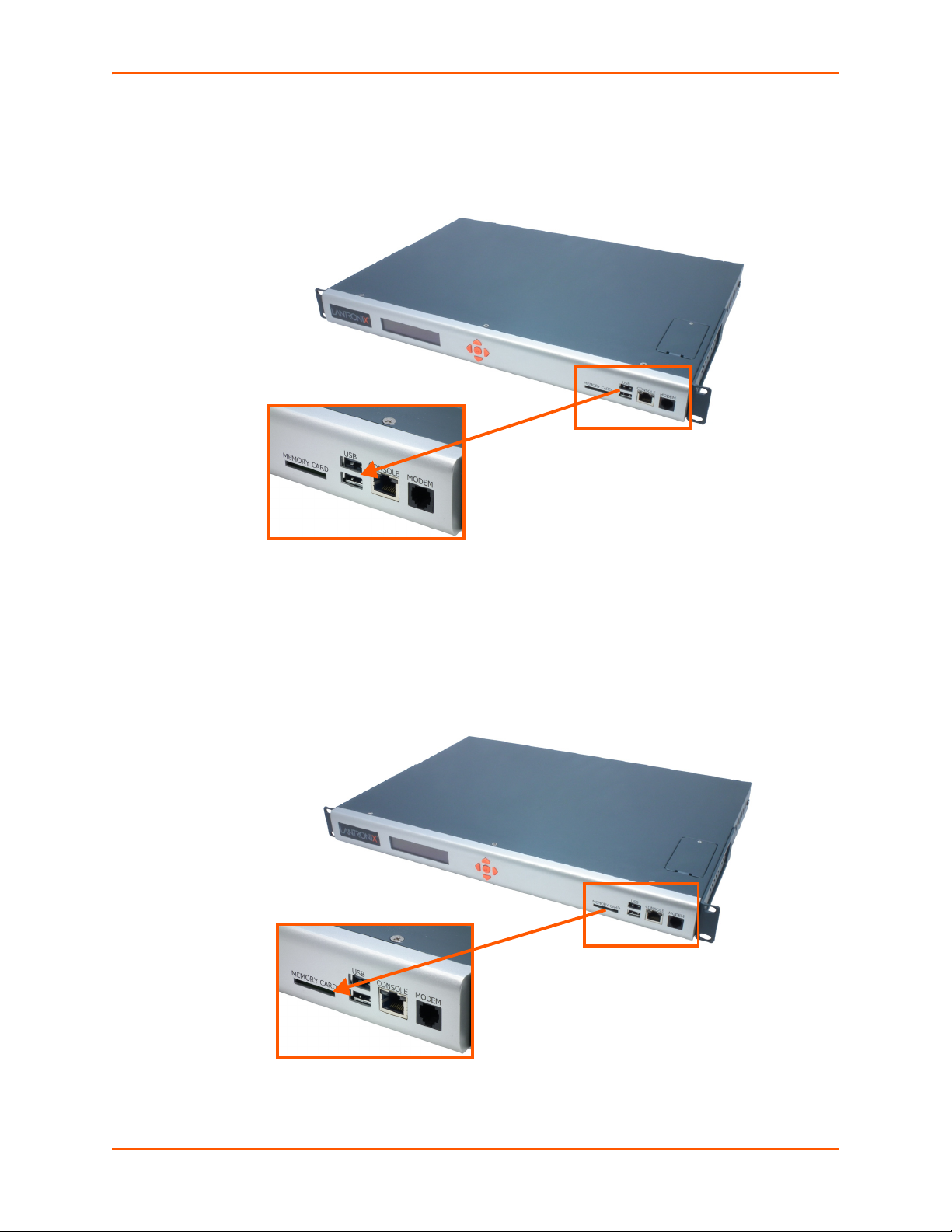
Memory Card Port
The SLC unit has a memory card port on the front panel of the unit which accepts SD cards.
Figure 2-8 Memory Card Port
SLC™ 8000 Advanced Console Manager User Guide 25
Page 26
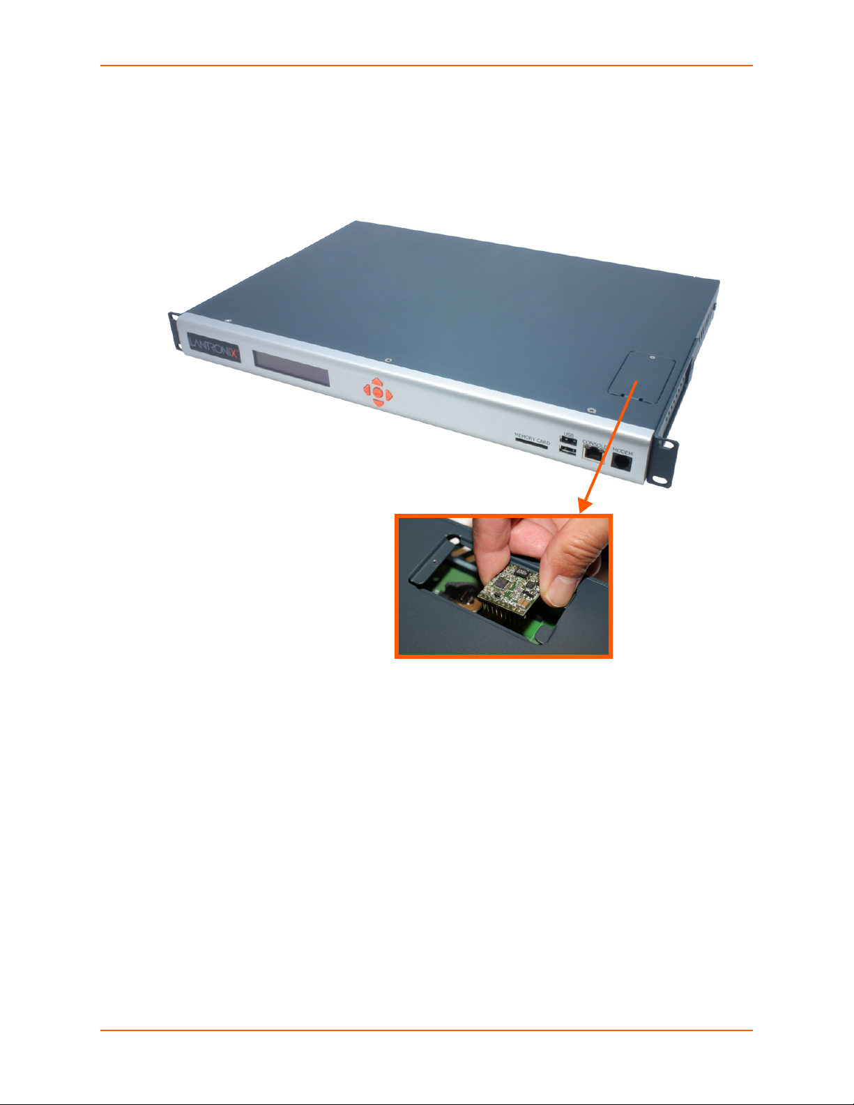
2: Introduction
Internal Modem
An internal modem can be installed in the SLC 8000 advanced console manager. See Modem
Installation on page 33 for instructions.
Figure 2-9 Internal Modem Location
SLC™ 8000 Advanced Console Manager User Guide 26
Page 27

3: Installation
This chapter provides a high-level procedure for installing the SLC advanced console manager
followed by more detailed information about the SLC connections and power supplies.
Caution: To avoid physical and electrical hazards, please read appendix,
Appendix A: Security Considerations on page 328 before installing the SLC
8000 advanced console managerSLC 8000 advanced console manager.
What's in the Box
In addition to the SLC unit, the following table lists components in the box and their corresponding
part numbers.
Part # Component Description Quantity
Cables:
200.2070A RJ45 to DB9F Adapter 1
200.0062 RJ45 to RJ45, Cat5, 6.6 ft (2 m) 1
500-153 RJ45 Loopback 1
Power Cords:
500-041-ACC For AC Supply Models: AC Power Cord included only 1 for Single
083-014-ACC For DC Supply Models: DC Installation Kit only 1
Table 3-1 Part Numbers and Descriptions
2 for Dual
Verify and inspect the contents of the SLC package using the enclosed packing slip or the table
above. If any item is missing or damaged, contact your place of purchase immediately.
Product Information Label
The product information label on the underside of the SLC 8000 advanced console manager
contains the following information about each SLC unit:
Part Number
Serial Number
Serial Number Bar Code
Date Code
Country of Manufacture
SLC™ 8000 Advanced Console Manager User Guide 27
Page 28

Technical Specifications
Table 3-2 SLC Technical Specifications
Component Description
Serial Interface (Device) (48) RJ45-type 8-conductor connectors which are individually configurable
Speed software selectable (300 to 230400 baud)
reversed by default. Do not use rolled cables and adapters when replacing an
SLC 8000 advanced console manager with the SLC 8000 model.
Serial Interface (Console) (1) RJ45-type 8-pin connector (DTE)
Speed software selectable (300 to 230400 baud)
LEDs:
Network Interface (2) 10/100/1000 Base-T RJ45 Ethernet
LEDs:
Power Supply AC
(single or dual)
Power Supply DC (dual) 20V to 72V input
Power Consumption Less than 25 watts
Dimensions 1U, 1.75 in x 17.25 in x 12 in
Weight 11.5 lbs or less, depending on options
Temperature
Relative Humidity Operating: 10% to 90% non-condensing; 40% to 60% recommended
USB Ports
Memory Card Single memory card slot supporting:
Modem
Universal AC power input: 100-240 VAC
50 or 60 Hz IEC 60320/C19IEC-type regional cord set included
Operating: 0 to 50°C (32 to 122°F), 30 to 90% RH, non-condensing
Storage: -20 to 80°C (-4 to 176°F), 10 to 90% RH, non-condensing
Storage: 10% to 90% non-condensing
(2) ports, type A, host USB 2.0 (HS, FS, LS)
SD
SDHC
300 bps to 56K bps data rate
Upstream 48K bps, downstream 56K bps
V.44 data compression (V92MB-U, V92HU)
V.42 bis and MNP-5 data compression
V.29 FastPOS support
Caller ID type I and II for select countries
Agency approvals: Transferable FCC68, CS03 and CTR21 certifications,
3: Installation
standard or reversed pinouts
Note: Device ports for the SLC 8000 advanced console manager are
Green light ON indicates data transmission activities
Yellow light ON indicates data receiving activities
Green light ON indicates a link at 1000 Base-T
Green light OFF indicates a link at other speeds or no link
Yellow light ON indicates a link is established
Yellow light blinking indicates activity
IEC60601-1 (Medical Electronics) compliant, CE Marking, IEC60950 approved
SLC™ 8000 Advanced Console Manager User Guide 28
Page 29

Physical Installation
Install the SLC 8000 advanced console manager in an EIA-standard 19-inch rack (1U tall) or as a
desktop unit. The SLC module uses convection cooling to dissipate excess heat.
To install the SLC 8000 advanced console manager in a rack:
1. Place the SLC unit in a 19-inch rack.
Warning: Do not to block the air vents on the sides of the SLC module. If you
mount the SLC advanced console manager in an enclosed rack, we
recommended that the rack have a ventilation fan to provide adequate
airflow through the SLC unit.
2. Connect the serial device(s) to the SLC unit ports. See the section, Connecting to a Device
Port (on page 29).
3. Choose one of the following options:
- To configure the SLC 8000 advanced console manager using the network, or to monitor
serial devices on the network, connect at least one SLC network port to a network. See
Connecting to Network Ports (on page 31).
- To configure the SLC unit using a dumb terminal or a computer with terminal emulation,
connect the terminal or PC to the SLC console port. See Connecting Terminals (on page
31).
3: Installation
4. Connect the power cord, and apply power. See AC Input (on page 32).
5. Wait approximately a minute for the boot process to complete.
When the boot process ends, the SLC host name and the clock appear on the LCD display.
Now you are ready to configure the network settings as described in Chapter 4: Quick Setup.
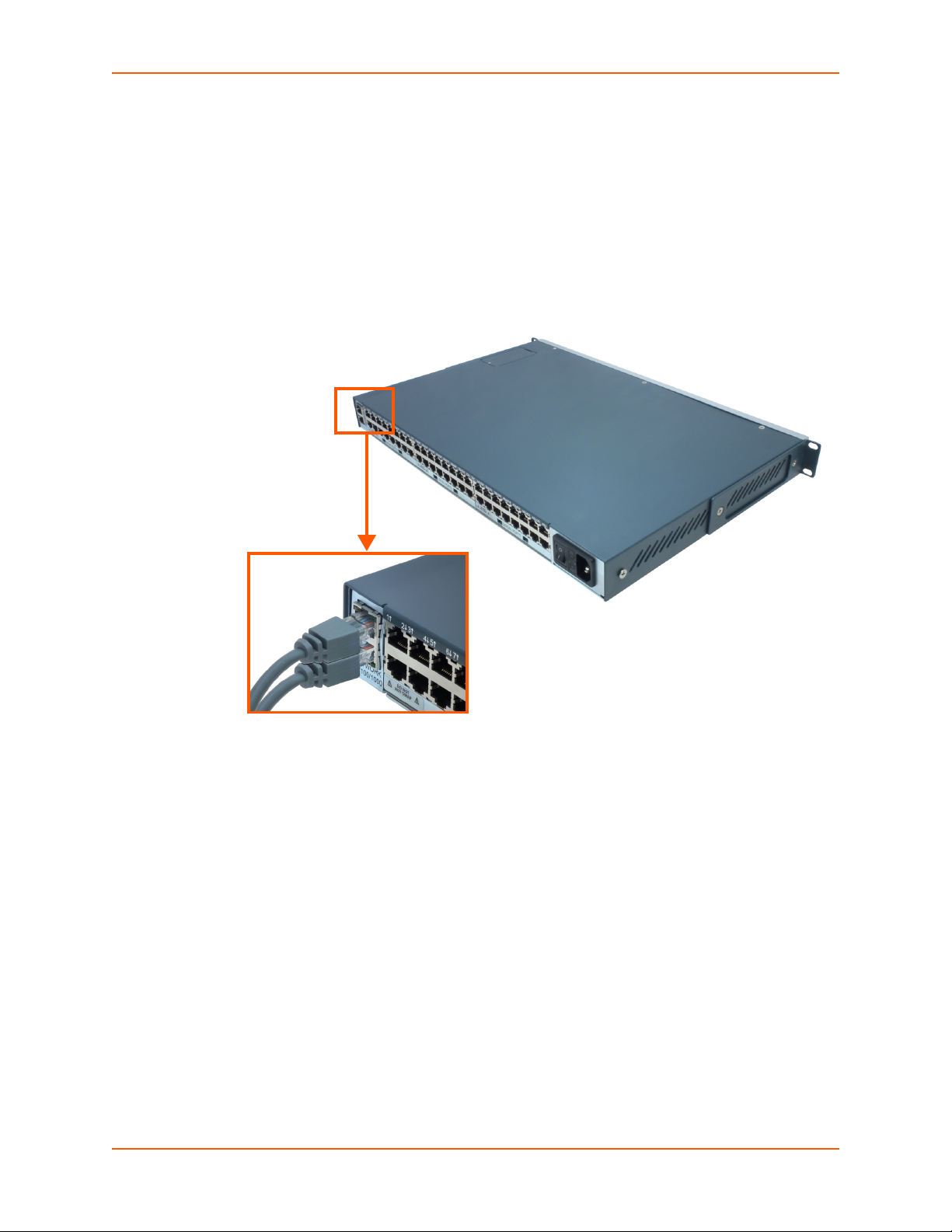
Connecting to a Device Port
You can connect almost any device that has a serial console port to a device port on the SLC 8000
advanced console manager for remote administration. The console port must support the RS232C interface.
Note: Many servers must either have the serial port enabled as a console or the
keyboard and mouse detached. Consult the server hardware and/or software
documentation for more information.
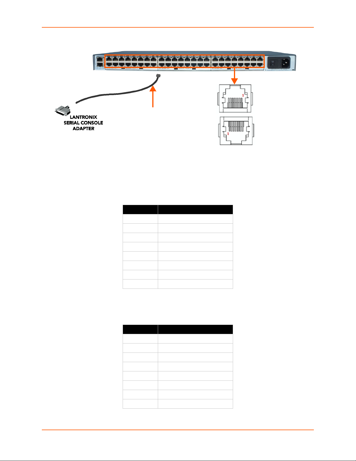
To connect to a device port:
1. Connect one end of the Cat 5 cable to the device port.
2. Connect the other end of the Cat 5 cable to a Lantronix serial console adapter.
Note: See Device Port Commands on page 115 to enable or disable reverse pinouts
through the CLI. Table 3-4, Table 3-5 and Figure 3-3 provide additional information on
reverse pinouts. Reference Appendix C: Adapters and Pinouts on page 331 for more
information about Lantronix adapters.
SLC™ 8000 Advanced Console Manager User Guide 29
Page 30
3: Installation
RJ45
CABLE
Figure 3-3 Device Port Connections (Back Side)
3. Connect the adapter to the serial console port on the serial device as shown in Figure 3-3.
Table 3-4 Console Port and Device Port (DTE) - Reverse Pinout Disabled
Pin Number Description
1 RTS (output)
2DTR (output)
3 TXD (output)
4Ground
5Ground
6 RXD (input)
7 DSR (input)
8 CTS (input)
Table 3-5 Device Port (DCE) - Reverse Pinout Enabled
Pin Number Description
1 CTS (input)
2 DSR (input)
3 RXD (input)
4Ground
5Ground
6 TXD (output)
7DTR (output)
8 RTS (output)
SLC™ 8000 Advanced Console Manager User Guide 30
Page 31

3: Installation
Modular Expansion for I/O Module
The SLC 8000 advanced console manager supports the flexibility to change the I/O module
configuration by offering a 16 port card for expansion. See Table 3-6. When device ports are
unused or unsupported, they are greyed out in the Port Number Bar. Bay 1 is the slot next to the
Ethernet ports and Bay 3 is the slot beside the power supply module.
Table 3-6 Available I/O Configurations
Connecting to Network Ports
The SLC network ports, 10/100/1000 Base-T Ethernet, allow remote access to the attached
devices and the system administrative functions. Use a standard RJ45-terminated Category 5
cable to connect to the network port. A CAT5e or better cable is recommended for use with a
1000 Base-T Ethernet connection.
Note: One possible use for the two Ethernet ports is to have one port on a private,
secure network, and the other on an unsecured network.
Connecting Terminals
The console port is for local access to the SLC 8000 advanced console manager and the attached
devices. You may attach a dumb terminal or a computer with terminal emulation to the console
port. The SLC console port uses RS-232C protocol and supports VT100 emulation. The default
baud rate is 9600.
To connect the console port to a terminal or computer with terminal emulation, Lantronix offers
optional adapters that provide a connection between an RJ45 jack and a DB9 or DB25 connector.
The console port is configured as DTE. See Appendix C: Adapters and Pinouts on page 331 for
more information, and our Web site at www.lantronix.com/support
Lookup on the Support menu.
SLC™ 8000 Advanced Console Manager User Guide 31
and click Cable/Adapter
Page 32

3: Installation
To connect a terminal:
1. Attach the Lantronix adapter to your terminal (typifcally a PN 200.2066A adapter) or your PC's
serial port (use PN 200.2070A adapter).
2. Connect the Cat 5 cable to the adapter, and connect the other end to the SLC console port.
3. Turn on the terminal or start your computer's communication program (e.g., HyperTerminal for
Windows XP or lower. For recent versions of Windows use a free terminal emulator such as
PuTTY or TeraTerm Pro).
4. Once the SLC 8000 advanced console manager is running, press Enter to establish
connection. You should see the model name and a login prompt on your terminal. You are
connected.
AC Input
The power supply module for the SLC controller accepts AC input voltage of 100-240 VAC, 50/60
HZ. Rear-mounted IEC-type AC power connectors are provided for universal AC power input.
(See What's in the Box on page 27.)
Caution: Disconnect all power supply modules before servicing to avoid electric shock.
Figure 3-7 AC Power Input
SLC™ 8000 Advanced Console Manager User Guide 32
Page 33

3: Installation
Modem Installation
Caution: TO REDUCE THE RISK OF FIRE, USE ONLY NO. 26 AWG OR LARGER (e.g., 24
AWG) UL LISTED OR CSA CERTIFIED TELECOMMUNICATION LINE CORD.
Attention: POUR RÉDUIRE LES RISQUES D'INCENDIE, UTILISER UNIQUEMENT DES
CONDUCTEURS DE TÉLÉCOMMUNICATIONS 26 AWG AU DE SECTION
SUPÉRLEURE.
Warning: RISK OF ELECTRICAL SHOCKS; DISCONNECT ALL POWER AND
PHONE LINES BEFORE SERVICING!
Caution: DEVICES INSIDE THE EQUIPMENT AND THE MODEM ARE ELECTROSTATIC -
SENSITIVE; DO NOT HANDLE EXCEPT AT A STATIC FREE WORKPLACE.
MODEM PART NUMBER
Lantronix 56KINTMODEM-01
MODEM SERVICING INSTRUCTIONS
You will need a medium size Phillips screw driver.
1. Turn off power to the SLC 8000 advanced console manager.
2. Locate the battery modem door on the top of the SLC unit.
3. Unscrew and lift the door off with the screw driver.
SLC™ 8000 Advanced Console Manager User Guide 33
Page 34

3: Installation
4. Take note of the orientation of the modem so that later you can install a new modem correctly
with the same orientation.
5. If there is a modem replacement, carefully lift the old modem out of its socket.
6. Install the new modem with correct orientation.
7. Make sure to have correct pin alignment.
SLC™ 8000 Advanced Console Manager User Guide 34
Page 35

8. Press the modem down to make sure it sits down all the way in the socket.
9. Double-check the new modem placement to make sure it is done properly.
10. Place the battery modem door back.
11. Tighten the door screw.
3: Installation
Battery Replacement
Caution: RISK OF EXPLOSION IF BATTERY IS REPLACED BY AN INCORRECT TYPE.
DISPOSE OF USED BATTERIES ACCORDING TO THE INSTRUCTIONS.
Attention: II Y A DANGER D'EXPLOSION S'IL Y A REMPLACEMENT INCORRECT DE LA
BATTERIE. REMPLACER UNIQUEMENT AVEC UNE BATTERIE DU MÊME TYPE
OU D'UN TYPE EQUIVALENT RECOMMANDÉ PAR LE CONSTRUCTEUR.
METTRE AU REBUT LES BATTERIES USAGÉES CONFORMÉMENT AUX
INSTRUCTIONS DU FABRICANT.
Caution: DEVICES INSIDE THE EQUIPMENT ARE ELECTROSTATIC -SENSITIVE; DO NOT
HANDLE EXCEPT AT A STATIC FREE WORKPLACE.
Battery Part Numbers
Panasonic BR2032 or equivalent (button cell lithium, non-rechargeable)
Caution: DO NOT USE BATTERY TYPE CR2032 SINCE IT HAS A LOWER OPERATING
TEMPERATURE RANGE.
SLC™ 8000 Advanced Console Manager User Guide 35
Page 36

3: Installation
DISPOSAL OF USED BATTERIES (from battery data sheet)
If not in a large quantity, button cell batteries contain so little Lithium that they do not qualify as
reactive hazardous waste. These batteries are safe for disposal in the normal municipal waste
stream.
If in a large quantity, disposal of button cell batteries should be performed by permitted,
professional firms knowledgeable in Federal, State and local hazardous waste transportation
and disposal requirements.
Caution: RISK OF FIRE, EXPLOSION AND BURNS. DO NOT RECHARGE, CRUSH, HEAT
ABOVE 212°F (100°C) OR INCINERATE.
Battery Replacement Instructions
Warning: RISK OF ELECTRICAL SHOCKS; DISCONNECT ALL POWER AND
PHONE LINE BEFORE SERVICING!
You will need a medium size Phillips screw driver.
1. Turn off power to the SLC 8000 advanced console manager.
2. Locate the battery modem door on the top of the SLC unit.
3. Unscrew and lift the door off with the screw driver.
4. If there is a modem, note the orientation of the modem so that later you can install it back
correctly.
SLC™ 8000 Advanced Console Manager User Guide 36
Page 37

5. If there is a modem, carefully lift the modem out of its socket.
6. Use fingers to lift the battery out of the socket.
3: Installation
Caution: DO NOT USE A METAL OBJECT TO PRY OUT THE BATTERY SINCE IT MAY
SHORT THE BATTERY AND DAMAGE THE BATTERY HOUSING.
7. Install the new battery with the (+) side up making sure the battery sits completely and
securely in the housing.
SLC™ 8000 Advanced Console Manager User Guide 37
Page 38

3: Installation
8. Re-install the modem with correct orientation.
a. Make sure also to have correct pin alignment.
b. Press the modem down to make sure it sits down all the way in the socket.
9. Double-check the battery and modem placements to make sure they are done properly.
10. Place the battery modem door back.
11. Tighten the door screw.
12. Reprogram the SLC system date-time after installing a new battery, if necessary.
SLC™ 8000 Advanced Console Manager User Guide 38
Page 39

4: Quick Setup
This chapter helps get the IP network port up and running quickly, so you can administer the SLC
advanced console manager using your network.
Recommendations
To set up the network connections quickly, we suggest you do one of the following:
Use the front panel LCD display and keypads.
Complete the quick setup (see Figure 4-5) on the web interface.
SSH to the command line interface and follow the Quick Setup script on the command line
interface.
Connect to the console port and follow the Quick Setup script on the command line interface.
Note: The first time you power up the SLC unit, Eth1 tries to obtain its IP address via
DHCP. If you have connected Eth1 to the network, and Eth1 is able to acquire an IP
address, you can view this IP address on the LCD or by running the Lantronix
DeviceInstaller™ application. If Eth1 cannot acquire an IP address, you cannot use
Telnet, SSH, or the web interface to run Quick Setup.
IP Address
Your SLC 8000 advanced console manager must have a unique IP address on your network. The
system administrator generally provides the IP address and corresponding subnet mask and
gateway. The IP address must be within a valid range, unique to your network, and in the same
subnet as your PC.
The following table lists the options for assigning an IP address to your SLC unit.
Method Description
DHCP A DHCP server automatically assigns the IP address and network settings.
BOOTP Non-dynamic predecessor to DHCP.
Front panel LCD display
and keypads
Serial port login to
command line interface
Table 4-1 Methods of Assigning an IP Address
The SLC 8000 advanced console manager is DHCP-enabled by default.
With the Eth1 network port connected to the network, and the SLC unit
powered up, Eth1 acquires an IP address, viewable on the LCD.
At this point, you can use SSH to connect to the SLC console manager or use
the web interface.
You manually assign the IP address and other basic network, console, and
date/time settings. If desired, you can restore the factory defaults.
You assign an IP address and configure the SLC unit using a terminal or a PC
running a terminal emulation program to the SLC serial console port
connection.
SLC™ 8000 Advanced Console Manager User Guide 39
Page 40

Method #1 Using the Front Panel Display
Before you begin, ensure that you have:
Unique IP address that is valid on your network (unless automatically assigned)
Subnet mask (unless automatically assigned)
Gateway (unless automatically assigned)
DNS settings (unless automatically assigned)
Date, time, and time zone
Console port settings: baud rate, data bits, stop bits, parity, and flow control
Make sure the SLC advanced console manager is plugged into power and turned on.
Front Panel LCD Display and Keypads
With the SLC unit powered up, you can use the front panel display and buttons to set up the basic
parameters.
Figure 4-2 Front Panel LCD Display and Five Button Keypad (Enter, Up, Down, Left, Right)
4: Quick Setup
The front panel display initially shows the hostname (abbreviated to 14 letters) and the date and
time.
When you click the right-arrow button, the SLC network settings displays. Using the five buttons on
the keypad, you can change the network, console port, and date/time settings and view the
firmware release version. If desired, you can restore the factory defaults.
Note: Have your information handy as the display times out without accepting any
unsaved changes if you take more than 30 seconds between entries.
Any changes made to the network, console port, and date/time settings take effect immediately.
Navigating
The front panel keypad has one Enter button (in the center) and four arrow buttons (up, left, right,
and down). Press the arrow buttons to navigate from one option to another, or to increment or
decrement a numerical entry of the selected option. Use the Enter button to select an option to
change or to save your settings.
SLC™ 8000 Advanced Console Manager User Guide 40
Page 41

4: Quick Setup
Left/Right Arrow
Current
Time
Eth1
Network
Settings
Console
Port
Settings
Date /
Time
Settings
Release Internal
Temp
User
Strings
Location Device
Ports
User ID &
Current
TIme
Eth1 IP
Address
Baud Rate,
Data Bits,
Stop Bits,
Parity,
Flow
Control
Time Zone Firmware
version and
date code
(display
only)
Reading in
Celsius &
Fahrenheit
Displays
configured
user
string(s), if
any.
Indicates
the Rack
(RK), Row
(RW) &
Cluster
(CW)
locations.
Detects the
connection
state of each
port:
0=No DSR
input signal
detected on
device port
1=DSR input
signal
detected on
device port
Eth1
Subnet
Mask
Data Bits Date/Time Restore
Factory
Defaults
Gateway Stop Bits
DNS1 Parity
DNS2 Flow
Control
DNS3
Up/
Down
Arrow
The following table lists the SLC navigation actions, buttons, and options.
Table 4-3 LCD Arrow Keypad Actions
Button Action
Right arrow To move to the next option (e.g., from Network Settings to Console Settings)
Left arrow To return to the previous option
Enter (center button) To enter edit mode
Up and down arrows Within edit mode, to increase or decrease a numerical entry
Right or left arrows Within edit mode, to move the cursor right or left
Enter To exit edit mode
Up and down arrows To scroll up or down the list of parameters within an option (e.g., from IP
Address to Mask)
Table 4-4 Front Panel Setup Options with Associated Parameters
Note: The individual screens listed from left to right in Table 4-4 can be enabled or
disabled for display on the SLC LCD screen. The order of appearance of the screens, if
enabled, along with the elected “Home Page” may vary on the LCD monitor according to
configuration. The internal temperature, user strings, location and device ports LCD
SLC™ 8000 Advanced Console Manager User Guide 41
menus are disabled by default. See LCD/Keypad (on page 251) for instructions on
enabling and disabling screens.
Page 42

4: Quick Setup
Entering the Settings
To enter setup information:
1. From the normal display (host name, date and time), press the right arrow button to display
Network Settings. The IP address for Eth1 displays.
Note: If you have connected Eth1 to the network, and Eth1 is able to acquire an IP
address through DHCP, this IP address displays, followed by the letter [D]. Otherwise, the
IP address displays as all zeros (000.000.000.000).
2. Press the Enter button on the keypad to enter edit mode. A cursor displays below one
character of the existing IP address setting.
3. To enter values:
- Use the left or right arrow to move the cursor to the left or to the right position.
- Use the up or down arrow to increment or decrement the numerical value.
4. When you have the IP address as you want it, press Enter to exit edit mode, and then press
the down arrow button. The Subnet Mask parameter displays.
Note: You must edit the IP address and the Subnet Mask together for a valid IP address
combination.
5. To save your entries for one or more parameters in the group, press the right arrow button.
The Save Settings? Yes/No prompt displays.
Note: If the prompt does not display, make sure you are no longer in edit mode.
6. Use the left/right arrow buttons to select Yes, and press the Enter button.
7. Press the right arrow button to move to the next option, Console Settings.
8. Repeat steps 2-7 for each setting.
9. Press the right arrow button to move to the next option, Date/Time Settings, and click Enter
to edit the time zone.
- To enter a US time zone, use the up/down arrow buttons to scroll through the US time
zones, and then press Enter to select the correct one.
- To enter a time zone outside the US, press the left arrow button to move up to the top level
of time zones. Press the up/down arrow button to scroll through the top level.
A time zone with a trailing slash (such as Africa/) has sub-time zones. Use the right arrow
button to select the Africa time zones, and then the up/down arrows to scroll through them.
Press Enter to select the correct time zone. To move back to the top-level time zone at
any time, press the left arrow.
10. To save your entries, press the right arrow button. The Save Settings? Yes/No prompt
displays.
Note: If the prompt does not display, make sure you are no longer in edit mode.
11. Use the left/right arrow buttons to select Yes, and press the Enter button.
12. To review the saved settings, press the up or down arrows to step through the current settings.
SLC™ 8000 Advanced Console Manager User Guide 42
Page 43

4: Quick Setup
When you are done, the front panel returns to the clock display. The network port resets to the
new settings, and you can connect to your IP network for further administration. You should be
able to SSH to the SLC 8000 advanced console manager through your network connection, or
access the Web interface through a Web browser.
Restoring Factory Defaults
To use the LCD display to restore factory default settings:
1. Press the right arrow button to move to the last option, Release.
2. Use the down arrow to move to the Restore Factory Defaults option. A prompt for the 6-digit
Restore Factory Defaults password displays.
3. Press Enter to enter edit mode.
4. Using the left and right arrows to move between digits and the up and down arrows to change
digits, enter the password (the default password is 999999).
Note: The Restore Factory Defaults password is only for the LCD. You can change it at
the command line interface using the admin keypad password command.
5. Press Enter to exit edit mode. If the password is valid, a Save Settings? Yes/No prompt
displays.
6. Select Yes and press Enter. When the process is complete, the SLC unit reboots.
Method #2 Quick Setup on the Web Page
After the unit has an IP address, you can use the Quick Setup page to configure the remaining
network settings. This page displays the first time you log into the SLC 8000 advanced console
manager only. Otherwise, the SLC Home page displays.
To complete the Quick Setup page:
1. Open a web browser (Firefox, Chrome or Internet Explorer web browsers with JavaScript
enabled).
2. In the URL field, type https:// followed by the IP address of your SLC console manager.
Note: The web server listens for requests on the unencrypted (HTTP) port (port 80) and
redirects all requests to the encrypted (HTTPS) port (port 443).
3. Log in using sysadmin as the user name and PASS as the password. The first time you log in to
the SLC unit, the Quick Setup page automatically displays. Otherwise, the Home page displays.
Note: To open the Quick Setup page at another time, click the Quick Setup tab.
SLC™ 8000 Advanced Console Manager User Guide 43
Page 44

Figure 4-5 Quick Setup
4: Quick Setup
Figure 4-6 Home
4. To accept the defaults, select the Accept default Quick Setup settings checkbox on the top
portion of the page and click the Apply button at the bottom of the page. Otherwise, continue
with step 5.
SLC™ 8000 Advanced Console Manager User Guide 44
Page 45

4: Quick Setup
Note: Once you click the Apply button on the Quick Setup page, you can continue using
the web interface to configure the SLC further.
5. Enter the following settings:
Network Settings
Note: Configurations with the same IP subnet on multiple interfaces (Ethernet or PPP)
are not currently supported.
Network Setting Description
Eth 1 Settings Obtain from DHCP: Acquires IP address, subnet mask, hostname and gateway
from the DHCP server. (The DHCP server may not provide the hostname
gateway, depending on its setup.) This is the default setting. If you select this
option, skip to Gateway.
Obtain from BOOTP: Lets a network node request configuration information from
a BOOTP "server" node. If you select this option, skip to Gateway.
Specify: Lets you manually assign a static IP address, generally provided by the
system administrator.
IP Address
(if specifying)
Subnet Mask If specifying an IP address, enter the subnet mask for the network on which the SLC
Default Gateway The IP address of the router for this network. There is no default.
Hostname The default host name is slcXXXX, where XXXX is the last 4 characters of the
Domain If desired, specify a domain name (for example, support.lantronix.com). The domain
Enter an IP address that is unique and valid on your network. There is no default.
Enter all IP addresses in dot-quad notation. Do not use leading zeros in the fields
for dot-quad numbers less than 100. For example, if your IP address is
172.19.201.28, do not enter 028 for the last segment.
Note: Currently, the SLC 8000 advanced console manager does not support
configurations with the same IP subnet on multiple interfaces (Ethernet or PPP).
unit resides. There is no default.
hardware address of Ethernet Port 1. There is a 64-character limit (contiguous
characters, no spaces). The host name becomes the prompt in the command line
interface.
name is used for host name resolution within the SLC 8000 advanced console
manager. For example, if abcd is specified for the SMTP server, and
mydomain.com is specified for the domain, if abcd cannot be resolved, the SLC unit
attempts to resolve abcd.mydomain.com for the SMTP server.
Date & Time Settings
Date & Time Setting Description
Change Date/Time Select the checkbox to manually enter the date and time at the SLC unit’s location.
Date From the drop-down lists, select the current month, day, and year.
Time From the drop-down lists, select the current hour and minute.
Time Zone From the drop-down list, select the appropriate time zone.
SLC™ 8000 Advanced Console Manager User Guide 45
Page 46

Administrator Settings
4: Quick Setup
Administrator
Setting
Sysadmin Password To change the password (e.g., from the default) enter a Sysadmin Password of up
Retype Password Re-enter the Sysadmin Password above in this field as a confirmation.
Description
to 64 characters.
6. Click the Apply button to save your entries.
Figure 4-7 Quick Setup Completed in Web Manager
Method #3 Quick Setup on the Command Line Interface
If the SLC 8000 advanced console manager does not have an IP address, you can connect a
dumb terminal or a PC running a terminal emulation program (VT100) to access the command line
interface. (See Connecting Terminals on page 31.) If the unit has an IP address, you can use SSH
or Telnet to connect to the SLC unit.
By default, Telnet is disabled and SSH is enabled. To enable Telnet, use the Services > SSH/Telnet/
Logging (on page 76).
To complete the command line interface Quick Setup script:
1. Do one of the following:
- With a serial terminal connection, power up, and when the command line displays, press
Enter.
- With a network connection, use an SSH program or Telnet program (if Telnet has been
enabled) to connect to xx.xx.xx.xx (the IP address in dot quad notation), and press
Enter. You should be at the login prompt.
2. Enter sysadmin as the user name and press Enter.
3. Enter PASS as the password and press Enter. The first time you log in, the Quick Setup script
runs automatically. Normally, the command prompt displays.
SLC™ 8000 Advanced Console Manager User Guide 46
Page 47

4: Quick Setup
Figure 4-8 Beginning of Quick Setup Script
Quick Setup will now step you through configuring a few basic settings.
The current settings are shown in brackets ('[]').
You can accept the current setting for each question by pressing
<return>.
4. Enter the following information at the prompts:
Note: To accept a default or to skip an entry that is not required, press Enter.
CLI Quick Setup
Settings
Config Eth1 Select one of the following:
IP Address (if
specifying)
Subnet Mask The subnet mask specifies the network segment on which the SLC 8000 advanced
Default Gateway IP address of the router for this network. There is no default.
Hostname
Domain If desired, specify a domain name (for example, support.lantronix.com). The domain
Time Zone If the time zone displayed is incorrect, enter the correct time zone and press Enter. If
Description
(1) obtain IP Address from DHCP: The unit will acquire the IP address, subnet
mask, hostname, and gateway from the DHCP server. (The DHCP server may or
may not provide the gateway and hostname, depending on its setup.) This is the
default setting.
(2) obtain IP Address from BOOTP: Permits a network node to request
configuration information from a BOOTP "server" node.
(3) static IP Address: Allows you to assign a static IP address manually. The IP
address is generally provided by the system administrator.
An IP address that is unique and valid on your network and in the same subnet as
your PC. There is no default.
If you selected DHCP or BOOTP, this prompt does not display.
Enter all IP addresses in dot-quad notation. Do not use leading zeros in the fields for
dot-quad numbers less than 100. For example, if your IP address is 172.19.201.28,
do not enter 028 for the last segment.
Note: Configurations with the same IP subnet on multiple interfaces (Ethernet or
PPP) are not currently supported.
console manager resides. There is no default. If you selected DHCP or BOOTP, this
prompt does not display.
The default host name is
address of Ethernet Port 1. There is a 64-character limit (contiguous characters, no
spaces).
Note: The host name becomes the prompt in the command line interface.
name is used for host name resolution within the SLC unit. For example, if abcd is
specified for the SMTP server, and mydomain.com is specified for the domain, if
abcd cannot be resolved, the SLC 8000 advanced console manager attempts to
resolve abcd.mydomain.com for the SMTP server.
the entry is not a valid time zone, the system guides you through selecting a time
zone. A list of valid regions and countries displays. At the prompts, enter the correct
region and country.
slc, where XXXX is the last 4 characters of the hardware
SLC™ 8000 Advanced Console Manager User Guide 47
Page 48

4: Quick Setup
CLI Quick Setup
Settings
Date/Time If the date and time displayed are correct, type n and continue. If the date and time
Sysadmin
password
Description
are incorrect, type y and enter the correct date and time in the formats shown at the
prompts.
Enter a new sysadmin password.
After you complete the Quick Setup script, the changes take effect immediately.
Figure 4-9 Quick Setup Completed in CLI
Quick Setup will now step you through configuring a few basic settings.
The current settings are shown in brackets ('[]').
You can accept the current setting for each question by pressing
<return>.
____Ethernet Port and Default Gateway___________________________________
The SLC8048 has two ethernet ports, Eth1 and Eth2.
By default, both ports are configured for DHCP.
Configure Eth1: (1) obtain IP Address from DHCP
(2) obtain IP Address from BOOTP
(3) static IP Address
Enter 1-3: [1]
The SLC8048 can be configured to use a default gateway.
Enter gateway IP Address: [none]
____Hostname____________________________________________________________
The current hostname is 'slc', and the current domain is '<undefined>'.
The hostname will be shown in the CLI prompt.
Specify a hostname: [slc]
Specify a domain: [<undefined>]
____Time Zone___________________________________________________________
The current time zone is 'GMT'.
Enter time zone: [GMT]
____Date/Time___________________________________________________________
The current time is Tue Feb 4 11:26:55 2014
Change the current time? [n]
____Sysadmin Password___________________________________________________
Enter new password: [<current password>]
Quick Setup is now complete.
[slc]>
SLC™ 8000 Advanced Console Manager User Guide 48
Page 49

Next Step
After completing quick setup on the SLC 8000 advanced console manager, you may want to
configure other settings. You can use the web page or the command line interface for
configuration.
For information about the web and the command line interfaces, go to Chapter 5: Web and
Command Line Interfaces.
To continue configuring the SLC unit, go to Chapter 6: Basic Parameters.
4: Quick Setup
SLC™ 8000 Advanced Console Manager User Guide 49
Page 50

5: Web and Command Line Interfaces
The SLC advanced console manager offers three interfaces for configuring the SLC unit: a
command line interface (CLI), a web interface, and an LCD with keypads on the front panel. This
chapter discusses the web and command line interfaces.
Note: See Chapter 4: Quick Setup on page 39 for instructions on using the LCD front
panel to configure basic network settings and web manager and CLI to perform quick
setup.
Web Manager
A web manager allows the system administrator and other authorized users to configure and
manage the SLC 8000 advanced console manager using most web browsers (Firefox, Chrome or
Internet Explorer web applications with JavaScript enabled). The Web Telnet and Web SSH
features require Java 1.1 (or later) support in the browser. The SLC unit provides a secure,
encrypted web interface over SSL (secure sockets layer).
Note: The web server listens for requests on the unencrypted (HTTP) port (port 80) and
redirects all requests to the encrypted (HTTPS) port (port 443).
SLC™ 8000 Advanced Console Manager User Guide 50
Page 51

The following figure shows a typical web page:
Logout
Button
Tabs
Options
Entry Fields
and Options
Apply Button
Port
Number
Bar
Icons
Help
Button
Figure 5-1 Web Page Layout
5: Web and Command Line Interfaces
The web page has the following components:
Tabs: Groups of settings to configure.
Options: Below each tab are options for specific types of settings.
Note: Only those options for which the currently logged-in user has rights display.
Port Number Bar:
- The light green LCD button allows you to configure the front panel LCD.
- The beige SD button allows you to configure the SD card, if a card is inserted. See
Chapter 9: USB/SD Card Port on page 157.
SLC™ 8000 Advanced Console Manager User Guide 51
Page 52

5: Web and Command Line Interfaces
- The gray U1 button allows you to configure the upper USB device (flash drive or modem)
plugged into the front panel USB connector. The gray U2 button allows you to configure
the lower USB device plugged into the front panel USB connector. See Chapter 9: USB/
SD Card Port on page 157.
- The brown MD button allows you to configure the internal modem, if an internal modem is
installed.
- The blue E1 and E2 buttons display the Network > Network Settings page.
- The number buttons allow you to select a port and display its settings. Only ports to which
the currently logged-in user has rights are enabled.
Below the bar are options for use with the port buttons. Selecting a port and the
Configuration option takes you to the Device Ports > Settings page. Selecting a port and
the WebSSH option displays the WebSSH window for the device port --if Web SSH is
enabled, and if SSH is enabled for the device port. Selecting the port and the Connected
Device button allows access to supported devices such as SLP power managers and/or
SensorSoft temperature and humidity probes connected to the device port.
- The yellow orange A and B buttons display the status of the power supplies.
Entry Fields and Options: Allow you to enter data and select options for the settings.
Note: For specific instructions on completing the fields on the web pages, see Chapters
5 through 12.
Apply Button: Apply on each web page makes the changes immediately and saves them so
they will be there when the SLC 8000 advanced console manager is rebooted.
Icons: The icon bar above the Main Menu has icons that display the following:
Home page.
Information about the SLC unit and Lantronix contact information.
Configuration site map.
Status of the SLC 8000 advanced console manager.
Help Button: Provides online Help for the specific web page.
Logging in
Only the system administrator or users with web access rights can log into the web manager. More
than one user at a time can log in, but the same user cannot login more than once.
To log in to the SLC web manager:
1. Open a web browser.
2. In the URL field, type https:// followed by the IP address of your SLC 8000 advanced
console manager.
3. To configure the SLC unit, use sysadmin as the user name and PASS as the password.
(These are the default values.)
Note: The system administrator may have changed the password using one of the
Quick Setup methods in the previous chapter.
SLC™ 8000 Advanced Console Manager User Guide 52
Page 53

The Lantronix SLC Quick Setup page displays automatically the first time you log in.
Subsequently, the Lantronix SLC Home page displays. (If you want to display the Quick Setup
page again, click Quick Setup on the main menu.)
Logging Out
To log off the SLC web interface:
1. Click the Logout button located on the upper left part of any user interface page. You are
brought back to the login screen when logout is complete.
Web Page Help
To view detailed information about an SLC web page:
1. Click the Help button to the right of any user interface page. Online Help contents will appear
in a new browser.
Command Line Interface
5: Web and Command Line Interfaces
A command line interface (CLI) is available for entering all the commands you can use with the
SLC 8000 advanced console manager. In this User Guide, after each section of instructions for
using the web interface, you will find the equivalent CLI commands. You can access the command
line interface using Telnet, SSH, or a serial terminal connection.
Note: By default, Telnet is disabled and SSH is enabled. To enable Telnet, use the
Services > SSH/Telnet/Logging web page, a serial terminal connection, or an SSH
connection. (See Chapter 7: Services.)
The sysadmin user and users with who have full administrative rights have access to the complete
command set, while all other users have access to a reduced command set based on their
permissions.
Logging In
To log in to the SLC command line interface:
1. Do one of the following:
- With a serial terminal connection, power up, and when the command line displays, press
Enter.
- If the SLC 8000 advanced console manager already has an IP address (assigned
previously or assigned by DHCP), Telnet (if Telnet has been enabled) or SSH to
xx.xx.xx.xx (the IP address in dot quad notation) and press Enter. The login prompt
displays.
2. To log in as the system administrator for setup and configuration, enter sysadmin as the user
name and press Enter.
3. Enter PASS as the password and press Enter. The first time you log in, the Quick Setup script
runs automatically. Normally, the command prompt displays. (If you want to display the Quick
Setup script again, use the admin quicksetup command.)
SLC™ 8000 Advanced Console Manager User Guide 53
Page 54

5: Web and Command Line Interfaces
Note: The system administrator may have changed the password using one of the
Quick Setup methods in the previous chapter.
To log in any other user:
1. Enter your SLC user name and press Enter.
2. Enter your SLC password and press Enter.
Logging Out
To log out of the SLC command line interface, type logout and press Enter.
Command Syntax
Commands have the following format:
<action> <category> <parameter(s)>
where
<action> is set, show, connect, admin, diag, or logout.
<category> is a group of related parameters whose settings you want to configure or view.
Examples are ntp, deviceport, and network.
<parameter(s)> is one or more name-value pairs in one of the following formats:
<parameter name> <aa|bb>
<parameter name> <Value>
User must specify one of the values (aa or bb) separated by a
vertical line ( | ). The values are in all lowercase and must be
entered exactly as shown. Bold indicates a default value.
User must specify an appropriate value, for example, an IP address.
The parameter values are in mixed case. Square brackets [ ]
indicate optional parameters.
Command Line Help
For general Help and to display the commands to which you have rights, type: help
For general command line Help, type: help command line
For more information about a specific command, type help followed by the command. For
example: help set network or help admin firmware
Tips
Type enough characters to identify the action, category, or parameter name uniquely. For
parameter values, type the entire value. For example, you can shorten:
set network port 1 state static ipaddr 122.3.10.1 mask 255.255.0.0
to
se net po 1 st static ip 122.3.10.1 ma 255.255.0.0
Use the Tab key to automatically complete action, category, or parameter names. Type a
partial name and press Tab either to complete the name if only one is possible, or to display
the possible names if more than one is possible. Following a space after the preceding name,
Tab displays all possible names.
SLC™ 8000 Advanced Console Manager User Guide 54
Page 55

5: Web and Command Line Interfaces
Should you make a mistake while typing, backspace by pressing the Backspace key and/or
the Delete key, depending on how you accessed the interface. Both keys work if you use
VT100 emulation in your terminal access program when connecting to the console port. Use
the left and right arrow keys to move within a command.
Use the up and down arrows to scroll through previously entered commands. If desired, select
one and edit it. You can scroll through up to 100 previous commands entered in the session.
To clear an IP address, type 0.0.0.0, or to clear a non-IP address value, type CLEAR.
When the number of lines displayed by a command exceeds the size of the window (the
default is 25), the command output is halted until the user is ready to continue. To display the
next line, press Enter, and to display the page, press the space bar. You can override the
number of lines (or disable the feature altogether) with the set cli command.
General CLI Commands
The following commands relate to the CLI itself.
To configure the current command line session:
set cli scscommands <enable|disable>
Allows you to use SCS-compatible commands as shortcuts for executing commands:
Note: Settings are retained between CLI sessions for local users and users listed in the
remote users list.
SCS Commands Commands
info 'show sysstatus'
version 'admin version'
reboot 'admin reboot'
poweroff 'admin shutdown'
listdev 'show deviceport names'
direct 'connect direct deviceport'
listen 'connect listen deviceport'
clear 'set locallog clear'
telnet 'connect direct telnet'
ssh 'connect direct ssh'
To set the number of lines displayed by a command:
set cli terminallines <disable|Number of lines>
Sets the number of lines in the terminal emulation (screen) for paging through text one screenful at
a time, if the SLC 8000 advanced console manager cannot detect the size of the terminal
automatically.
To show current CLI settings:
show cli
SLC™ 8000 Advanced Console Manager User Guide 55
Page 56

5: Web and Command Line Interfaces
To view the last 100 commands entered in the session:
show history
To clear the command history:
set history clear
To view the rights of the currently logged-in user:
show user
Note: For information about user rights, see Chapter 11: User Authentication.
Table 5-2 CLI Keyboard Shortcuts
Keyboard Shortcut Description
Control + [a] Move to the start of the line.
Control + [e] Move to the end of the line.
Control + [b] Move back to the start of the current word.
Control + [f] Move forward to the end of the next word.
Control + [u] Erase from cursor to the beginning of the line.
Control + [k] Erase from cursor to the end of the line.
SLC™ 8000 Advanced Console Manager User Guide 56
Page 57

6: Basic Parameters
This chapter explains how to set the following basic configuration settings for the SLC advanced
console manager using the SLC web interface or the CLI:
Network parameters that determine how the SLC 8000 advanced console manager interacts
with the attached network
Firewall and routing
Date and time
Note: If you entered some of these settings using a Quick Setup procedure, you may
update them here.
Requirements
If you assign a different IP address from the current one, it must be within a valid range, unique to
your network, and with the same subnet mask as your workstation.
To configure the unit, you need the following information:
Eth1 IP address: ________ - ________ - ________ - ________
Subnet mask: ________ - ________ - ________ - ________
Eth2 IP address (optional): ________ - ________ - ________ - ________
Subnet mask (optional): ________ - ________ - ________ - ________
Gateway: ___________ - ___________ - ___________ - ___________
DNS: ___________ - ___________ - ___________ - ___________
SLC™ 8000 Advanced Console Manager User Guide 57
Page 58

6: Basic Parameters
To enter settings for one or both network ports:
1. Click the Network tab and select the Network Settings option. The following page displays:
Figure 6-1 Network > Network Settings
SLC™ 8000 Advanced Console Manager User Guide 58
Page 59

6: Basic Parameters
2. Enter the following information:
Ethernet Interfaces (Eth1 and Eth2)
Note: Configurations with the same IP subnet on multiple interfaces (Ethernet or PPP)
are not currently supported.
Eth 1 Settings
or
Eth 2 Settings
Disabled: If selected, disables the network port.
Obtain from DHCP: Acquires IP address, subnet mask, hostname and gateway
from the DHCP server. (The DHCP server may not provide the hostname
gateway, depending on its setup.) This is the default setting. If you select this
option, skip to Gateway.
Obtain from BOOTP: Lets a network node request configuration information
from a BOOTP "server" node. If you select this option, skip to Gateway.
Specify: Lets you manually assign a static IP address, generally provided by the
system administrator.
IP Address
(if specifying)
Enter an IP address that will be unique and valid on your network. There is no
default.
Enter all IP addresses in dot-quad notation. Do not use leading zeros in the
fields for dot-quad numbers less than 100. For example, if your IP address is
172.19.201.28, do not enter 028 for the last segment.
Note: Currently, the SLC unit does not support configurations with the same IP
subnet on multiple interfaces (Ethernet or PPP).
Subnet Mask If specifying an IP address, enter the network segment on which the SLC unit
resides. There is no default.
IPv6 Address Address of the port in IPv6 format.
Note: The SLC 8000 advanced console manager supports IPv6 connections for a
limited set of services: the web, SSH, and Telnet.
IPv6 addresses are written as 8 sets of 4-digit hexadecimal numbers separated by
colons. There are several rules for modifying the address. For example:
1234:0BCD:1D67:0000:0000:8375:BADD:0057 may be shortened to
1234:BCD:1D67::8375:BADD:57.
IPv6 Address
(Link Local)
Mode Select the direction (full duplex or half-duplex) and speed (10, 100, or 1000 Mbit) of
MTU Specifies the maximum transmission unit (MTU) or maximum packet size of
Multicast Displays the multicast address of the Ethernet port.
Enable IPv6 Select this box to enable the IPv6 protocol. Disabled by default.
Ethernet Bonding Ethernet 1 and Ethernet 2 can be bonded to support redundancy (Active Backup),
An IPv6 address that is intended only for communications within the segment of a
local network.
data transmission. The default is Auto, which allows the Ethernet port to autonegotiate the speed and duplex with the hardware endpoint to which it is
connected.
packets at the IP layer (OSI layer 3) for the Ethernet port. When fragmenting a
datagram, this is the largest number of bytes that can be used in a packet.
aggregation (802.3ad), and load balancing. Disabled by default. Note that if
Ethernet Bonding is enabled, assigning individual IP Addresses to Device Ports is
not supported.
SLC™ 8000 Advanced Console Manager User Guide 59
Page 60

6: Basic Parameters
Enable IP
Forwarding
IP forwarding enables network traffic received on one interface (Eth1, Eth2, or an
external/USB modem attached to the SLC unit with an active PPP connection) to
be transferred out another interface (any of the above). The default behavior (if IP
forwarding is disabled) is for network traffic to be received but not routed to another
destination.
Enabling IP forwarding is required if you enable Network Address Translation
(NAT) for any device port modem or USB/ISDN modem. IP forwarding allows a
user accessing the SLC 8000 advanced console manager over a modem to access
the network connected to Eth1 or Eth2.
Note: Configurations with the same IP subnet on multiple interfaces (Ethernet or PPP)
are not currently supported.
Gateway
Default IP address of the router for this network.
If this has not been set manually, any gateway acquired by DHCP for Eth1 or Eth2
displays.
All network traffic that matches the Eth1 IP address and subnet mask is sent out
Eth1. All network traffic that matches the Eth2 IP address and subnet mask is sent
out Eth 2.
If you set a default gateway, any network traffic that does not match Eth1 or Eth2 is
sent to the default gateway for routing.
DHCP-Acquired Gateway acquired by DHCP for Eth1 or Eth2. View only.
Precedence Indicates whether the gateway acquired by DHCP or the default gateway takes
precedence. The default is DHCP Gateway. If the DHCP Gateway is selected and
both Eth1 and Eth2 are configured for DHCP, the SLC unit gives precedence to the
Eth1 gateway.
Alternate An alternate IP address of the router for this network, to be used if an IP address
usually accessible through the default gateway fails to return one or more pings.
IP Address to Ping IP address to ping to determine whether to use the alternate gateway.
Ethernet Port to Ping Ethernet port to use for the ping.
Delay between Pings Number of seconds between pings
Number of Failed
Pings
Number of pings that fail before the SLC 8000 advanced console manager uses the
alternate gateway.
Hostname & Name Servers
Hostname
Domain If desired, specify a domain name (for example, support.lantronix.com). The domain
The default host name is
hardware address of Ethernet Port 1. There is a 64-character limit (contiguous
characters, no spaces). The host name becomes the prompt in the command line
interface.
name is used for host name resolution within the SLC unit. For example, if abcd is
specified for the SMTP server, and mydomain.com is specified for the domain, if
abcd cannot be resolved, the SLC 8000 advanced console manager attempts to
resolve abcd.mydomain.com for the SMTP server.
SLC™ 8000 Advanced Console Manager User Guide 60
slcXXXX, where XXXX is the last 4 characters of the
Page 61

6: Basic Parameters
DNS Servers
#1 - #3 Configure up to three name servers. #1 is required if you choose to configure DNS
(Domain Name Server) servers.
The first three DNS servers acquired via DHCP through Eth1 and/or Eth2 display
automatically.
DHCP-Acquired DNS Servers
#1 - #3 Displays the IP address of the name servers if automatically assigned by DHCP.
TCP Keepalive Parameters
Start Probes Number of seconds the SLC unit waits after the last transmission before sending the
first probe to determine whether a TCP session is still alive. The default is 600
seconds (10 minutes).
Number of Probes Number of probes the SLC 8000 advanced console manager sends before closing a
session. The default is 5.
Interval The number of seconds the SLC unit waits between probes. The default is 60
seconds.
3. To save your entries, click the Apply button. Apply makes the changes immediately and
saves them so they will be there when the SLC 8000 advanced console manager is rebooted.
Ethernet Counters
The Network > Network Settings page displays statistics for each of the SLC Ethernet ports since
boot-up. The system automatically updates them.
Note: For Ethernet statistics for a smaller time period, use the diag perfstat
command.
Network Commands
The following CLI commands correspond to the web page entries described above.
To configure Ethernet port 1 or 2:
set network port <1|2> <parameters>
Parameters
mode <auto|10mbit-half|100mbit-half|
10mbit-full|100mbit-full|1000mbit-full>
state <dhcp|bootp|static|disable>
[ipaddr <IP Address> mask <Mask>]
[ipv6addr <IP v6 Address|Prefix>]
To configure up to three DNS servers:
set network dns <1|2|3> ipaddr <IP Address>
SLC™ 8000 Advanced Console Manager User Guide 61
Page 62

6: Basic Parameters
To set the default and alternate network gateways:
set network gateway <parameters>
Parameters
default <IP Address>
precedence <dhcp|default>
alternate <IP Address>
pingip <IP Address>
ethport <1 or 2>
pingdelay <1-250 seconds>
failedpings <1-25>
The alternate gateway is used if an IP address usually accessible through the default gateway fails
to return one or more pings.
To set the SLC host name and domain name:
set network host <Hostname> [domain <Domain Name>]
To set TCP Keepalive and IP Forwarding network parameters:
set network <parameters>
Parameters
interval <1-99999 Seconds>
ipforwarding <enable|disable>
probes <Number of Probes>
startprobes <1-99999 Seconds>
To view all network settings:
show network all
To view Ethernet port settings and counters:
show network port <1|2>
To view DNS settings:
show network dns
To view gateway settings:
show network gateway
To view the host name of the SLC 8000 advanced console manager:
show network host
SLC™ 8000 Advanced Console Manager User Guide 62
Page 63

IP Filter
IP filters (also called a rule set) act as a firewall to allow or deny individual or a range of IP
addresses, ports, and protocols. When a network connection is configured to use an IP filter, all
network traffic through that connection is compared, in order, to the rules of that filter. Network
traffic may be allowed to pass, it may be dropped (without notice), or it may be rejected (sends
back an error packet) depending upon the rules of that filter rule set.
The administrator uses the Network > IP Filter page to view, add, edit, delete, and map IP filters,
Warning: IP filters configuration is a feature for advanced users. Adding and
Viewing IP Filters
You can view a list of filters and a table showing how each filter is mapped to an interface.
To view a list of IP filters:
1. Click the Network tab and select the IP Filter option. The following page displays:
6: Basic Parameters
enabling IP filter sets incorrectly can disable your SLC unit.
Figure 6-2 Network > IP Filter
Mapping Rulesets
The administrator can assign an IP Filter Rule Set to a network interface (Ethernet interface), a
modem connected to a device port, or a USB modem or an internal modem (if installed).
To map a ruleset to a network interface:
1. Click the Network tab and select the IP Filter option. The Network > IP Filter page displays.
2. Select the IP filter rule set to be mapped.
SLC™ 8000 Advanced Console Manager User Guide 63
Page 64

6: Basic Parameters
3. From the Interface drop-down list, select the interface and click the Map Ruleset button. The
Interface and rule set display in the IP Filter Mappings table.
To delete a mapping:
1. Click the Network tab and select the IP Filter option. The Network > IP Filter page displays.
2. Select the mapping from the list and click the Delete Mappings button. The mapping no
longer displays.
3. Click the Apply button.
Enabling IP Filters
On the Network > IP Filter page, you can enable all filters or disable all filters.
Note: There is no way to enable or disable individual filters.
To enable IP filters:
1. Enter the following:
Enable IP Filter Select the Enable IP Filter checkbox to enable all filters, or clear the checkbox
to disable all filters. Disabled by default.
Packets Dropped Displays the number of data packets that the filter ignored (did not respond to).
View only.
Packets Rejected Displays the number of data packets that the filter sent a “rejected” response to.
View only.
Test Timer Timer for testing IP Filter rulesets. Select No to disable the timer. Select Yes,
minutes (1-120) to enable the timer and enter the number of minutes the timer
should run. The timer automatically disables the IP Filters when the time
expires.
Time Remaining Indicates how many minutes are left on the timer before it expires and IP Filters
disabled. View only.
Configuring IP Filters
The administrator can add, edit, delete, and map IP filters.
Note: A configured filter has no effect until it is mapped to a network interface.
See Mapping Rulesets on page 63.
To add an IP filter:
1. On the Network > IP Filter page, click the Add Ruleset button. The following page displays:
SLC™ 8000 Advanced Console Manager User Guide 64
Page 65

6: Basic Parameters
Figure 6-3 Network > IP Filter Ruleset (Adding/Editing Rulesets)
Rulesets can be added or updated on this page.
2. Enter the following:
Ruleset Name Name that identifies a filter; may be composed of letters, numbers, and hyphens
only. (The name cannot start with a hyphen.)
Example:
FILTER-2
Rule Parameters
IP Address(es) Specify a single IP address to act as a filter.
Example:
Subnet Mask Specify a subnet mask to act determine how much of the address should apply to
the filter.
Example:
Protocol From the drop-down list, select the type of protocol through which the filter will
operate. The default setting is All.
172.19.220.64 – this specific IP address only
255.255.255.255 to specify the whole address should apply.
SLC™ 8000 Advanced Console Manager User Guide 65
Page 66

6: Basic Parameters
Port Range Enter a range of destination TCP or UDP port numbers to be tested. An entry is
required for TCP, TCP New, TCP Established, and UDP, and is not allowed for
other protocols. Separate multiple ports with commas. Separate ranges of ports by
colons.
Examples:
22 – filter on port 22 only
23,64,80 – filter on ports 23, 64 and 80
23:64,80,143:150 – filter on ports 23 through 64, port 80 and ports 143 through
150
Action Select whether to Drop, Reject, or Allow communications for the specified IP
address, subnet mask, protocol, and port range. Drop ignores the packet with no
notification. Reject ignores the packet and sends back an error message. Allow
permits the packet through the filter.
Generate rule to
allow service
You may wish to “punch holes” in your filter set for a particular protocol or service.
For instance, if you have configured your NIS server and wish to create an opening
in your filter set, select the NIS option and click the Add Rule button. This entry
adds a new rule to your filter set using the NIS -configured IP address. Other
services and protocols added automatically generate the necessary rule to allow
their use.
3. Click the right arrow button to add the new rule to the bottom of the Rules list box on the
right. A maximum of 64 rules can be created for each ruleset.
4. To remove a rule from the filter set, highlight that line and click the left arrow. The rule
populates the rule definition fields, allowing you to make minor changes before reinserting the
rule. To clear the definition fields, click the Clear button.
5. To change the order of priority of the rules in the list box, select the rule to move and use the
up or down arrow buttons on the right side of the filter list box.
6. To save, click the Apply button. The new filter displays in the menu tree.
Note: To add another new filter rule set, click the Back to IP Filter link to return to the
Network > IP Filter page.
SLC™ 8000 Advanced Console Manager User Guide 66
Page 67

Updating an IP Filter
To update an IP filter rule set:
1. From the Network > IP Filter page, the administrator selects the IP filter ruleset to be edited
and clicks the Edit Ruleset button to return to the Network > IP Filter Ruleset (Adding/Editing
Rulesets) page (see Figure 6-3).
2. Edit the information as desired and click the Apply button.
Deleting an IP Filter
To delete an IP filter rule set:
1. On the Network > IP Filter page, the administrator selects the IP filter ruleset to be deleted and
clicks the Delete Ruleset button.
IP Filter Commands
6: Basic Parameters
The following CLI commands correspond to the web page entries described above.
To enable or disable IP filtering for incoming network traffic:
set ipfilter state
To set IP filter mapping:
set ipfilter mapping <parameters>
Parameters
ethernet <1|2> state <disable>
ethernet <1|2> state <enable> ruleset <Ruleset Name>
deviceport <1..48> state <disable>
deviceport <1..48> state <enable> ruleset <Ruleset Name>
internal modem state <disable>
internal modem state <enable> ruleset <Ruleset Name>
usbport <U1|U2> state <disable>
usbport <U1|U2> state <enable> ruleset <Ruleset Name>
To set IP filter rules:
set ipfilter rules <parameters>
Parameters
add <Ruleset Name>
delete <Ruleset Name>
edit <Ruleset Name> <Edit Parameters>
Edit Parameters:
append
insert <Rule Number>
SLC™ 8000 Advanced Console Manager User Guide 67
Page 68

replace <Rule Number>
delete <Rule Number>
Routing
The SLC 8000 advanced console manager allows you to define static routes and, for networks
using Routing Information Protocol (RIP)-capable routes, to enable the RIP protocol to configure
the routes dynamically.
To configure routing settings:
1. Click the Network tab and select the Routing option. The following page displays:
6: Basic Parameters
Figure 6-4 Network > Routing
2. Enter the following:
Dynamic Routing
Enable RIP Select to enable Dynamic Routing Information Protocol (RIP) to assign routes
automatically. Disabled by default.
RIP Version Select the RIP version. The default is 2.
SLC™ 8000 Advanced Console Manager User Guide 68
Page 69

Static Routing
6: Basic Parameters
Enable Static
Routing
Select to assign the routes manually. The system administrator usually provides the
routes. Disabled by default.
To add a static route, enter the IP Address, Subnet Mask, and Gateway for the
route and click the Add/Edit Route button. The route displays in the Static Routes
table. You can add up to 64 static routes.
To edit a static route, select the radio button to the right of the route, change the IP
Address, Subnet Mask, and Gateway fields as desired, and click the Add/Edit
Route button.
To delete a static route, select the radio button to the right of the route and click the
Delete Route button.
3. Click the Apply button.
Note: To display the routing table, status or specific report, see the section,
Status/Reports on page 244.
Equivalent Routing Commands
The following CLI commands correspond to the web page entries described above.
To configure static or dynamic routing:
set routing [parameters]
Parameters
rip <enable|disable>
route <1-64> ipaddr <IP Address> mask <Netmask> gateway <IP Address>
static <enable|disable>
version <1|2|both>
VPN
Note: To delete a static route, set the IP address, mask, and gateway parameters to
0.0.0.0.
To set the routing table to display IP addresses (disable) or the corresponding host names (enable):
show routing [resolveip <enable|disable>] [email <Email Address>]
Note: You can optionally email the displayed information.
This page can be used to create a Virtual Private Network (VPN) tunnel to the SLC 8000 advanced
console manager for secure communication between the SLC unit and a remote host or gateway.
The SLC 8000 advanced console manager supports IPSec tunnels using Encapsulated Security
Payload (ESP). The SLC unit supports host-to-host, net-to-net, host-to-net, and roaming user
tunnels.
Note: To allow VPN tunnel access if the SLC firewall is enabled, traffic to UDP ports 500
and 4500 from the remote host should be allowed, as well as protocol ESP from the
remote host.
SLC™ 8000 Advanced Console Manager User Guide 69
Page 70

6: Basic Parameters
To complete the VPN page:
1. Click the Network tab and select the VPN option. The following page displays:
Figure 6-5 Network > VPN
2. Enter the following:
Enable VPN Tunnel Select to create a tunnel.
Name The name assigned to the tunnel. Required to create a tunnel.
Ethernet Port Select ethernet port 1 or 2.
Remote Host The IP address of the remote host's public network interface. The special
value of any can be entered if the remote host is a roaming user who may
not have the same IP address each time a tunnel is created. In this case, it
is recommended that the Remote Id also be configured.
SLC™ 8000 Advanced Console Manager User Guide 70
Page 71

6: Basic Parameters
Remote Id How the remote host should be identified for authentication. The Id is used
to select the proper credentials for communicating with the remote host.
Remote Hop/Router If the remote host is behind a gateway, this specifies the IP address of the
gateway's public network interface.
Remote Subnet(s) One or more subnets behind the remote host, expressed in CIDR notation
(IP address/mask bits). If multiple subnets are specified, the subnets should
be separated by a comma.
Local Id How the SLC 8000 advanced console manager should be identified for
authentication. The Id is used by the remote host to select the proper
credentials for communicating with the SLC advanced console manager.
Local Hop/
Router
Local Subnet(s) One or more subnets behind the SLC 8000 advanced console manager,
IKE Negotiation The Internet Key Exchange (IKE) protocol is used to exchange security
IKE Encryption The type of encryption, 3DES or AES, used for IKE negotiation. Any can be
Authentication (IKE) The type of authentication, SHA1 or MD5, used for IKE negotiation. Any
DH Group (IKE) The Diffie-Hellman Group, 2 or 5, used for IKE negotiation. Any can be
ESP Encryption The type of encryption, 3DES or AES, used for encrypting the data sent
Authentication (ESP) The type of authentication, SHA1 or MD5, used for authenticating data sent
DH Group (ESP) The Diffie-Hellman Group, 2 or 5, used for the key exchange for data sent
If the SLC unit is behind a gateway, this specifies the IP address of the
gateway's public network interface.
expressed in CIDR notation (IP address/mask bits). If multiple subnets are
specified, the subnets should be separated by a comma.
options between two hosts who want to communicate via IPSec. The first
phase of the protocol authenticates the two hosts to each other and
establishes the Internet Security Association Key Management Protocol
Security Association (ISAKMP SA). The second phase of the protocol
establishes the cryptographic parameters for protecting the data passed
through the tunnel, which is the IPSec Security Association (IPSec SA). The
IPSec SA can periodically be renegotiated to ensure security. The IKE
protocol can use one of two modes: Main Mode, which provides identity
protection and takes longer, or Aggressive Mode, which provides no
identity protection but is quicker. With Aggressive Mode, there is no
negotiation of which cryptographic parameters will be used; each side must
give the correct cryptographic parameters in the initial package of the
exchange, otherwise the exchange will fail. If Aggressive Mode is used, the
IKE Encryption, IKE Authentication, and IKE DH Group must be
specified.
selected if the two sides can negotiate which type of encryption to use.
can be selected if the two sides can negotiate which type of authentication
to use.
selected if the two sides can negotiate which Diffie-Hellman Group to use.
through the tunnel. Any can be selected if the two sides can negotiate
which type of encryption to use.
through the tunnel. Any can be selected if the two sides can negotiate
which type of authentication to use.
through the tunnel. Any can be selected if the two sides can negotiate
which Diffie-Hellman Group to use.
SLC™ 8000 Advanced Console Manager User Guide 71
Page 72

6: Basic Parameters
Authentication The type of authentication used by the host on each side of the VPN tunnel
to verify the identity of the other host. For RSA Public Key, each host
generates a RSA public-private key pair, and shares its public key with the
remote host. The RSA Public Key for the SLC 8000 advanced console
manager (which has 2192 bits) can be viewed at either the web or CLI. For
Pre-Shared Key, each host enters the same passphrase to be used for
authentication.
RSA Public Key for
Remote Host
Pre-Shared Key If Pre-Shared Key is selected for authentication, enter the key.
Retype Pre-Shared Key If Pre-Shared Key is selected for authentication, re-enter the key.
Perfect Forward Secrecy When a new IPSec SA is negotiated after the IPSec SA lifetime expires, a
Mode Configuration Client If this is enabled, the SLC unit can receive network configuration from the
XAUTH Client If this is enabled, the SLC 8000 advanced console manager will send
XAUTH Login (Client) If XAUTH Client is enabled, this is the login used for authentication.
XAUTH Password If XAUTH Client is enabled, this is the password used for authentication.
Retype Password If XAUTH Client is enabled, this is the password used for authentication.
If RSA Public Key is selected for authentication, enter the public key for the
remote host.
new Diffie-Hellman key exchange can be performed to generate a new
session key to be used to encrypt the data being sent through the tunnel. If
this is enabled, it provides greater security, since the old session keys are
destroyed.
remote host. This allows the remote host to assign an IP address/netmask
to the SLC advanced console manager side of the VPN tunnel.
authentication credentials to the remote host if they are requested. XAUTH,
or Extended Authentication, can be used as an additional security measure
on top of the Pre-Shared Key or RSA Public Key.
3. To save, click Apply button.
4. To see a details of the VPN tunnel connection, including the cryptographic algorithms used,
select the View Detailed Status link.
5. To see the last 100 lines of the logs associated with the VPN tunnel, select the View VPN
Logs link.
6. To see the RSA public key for the SLC 8000 advanced console manager (required for
configuring the remote host if RSA Public Keys are being used), select the View SLC RSA
Public Key link.
Configuring an IPsec VPN Tunnel through the CLI
1. Set vpn <parameters>:
tunnel <enable|disable>
ethport <1|2>
auth <rsa|psk>
remotehost <RemoteHost IP Address or name>
remoteid <Authentication name>
remotehop <IP Address>
remotesubnet <one or more subnets in CIDR notation>
localid <Authentication Name>
localhop <IP Address>
SLC™ 8000 Advanced Console Manager User Guide 72
Page 73

6: Basic Parameters
localsubnet <one or more subnets in CIDR notation>
ikenegotation <main|aggressive>
ikeenc <any|3des|aes>
ikeauth <any|sha1|md5>
ikedhgroup <any|dh2|dh5>
espenc <any|3des|aes>
espauth <any|sha1|md5>
espdhgroup <any|dh2|dh5>
pfs <enable|disable>
modeconfig <enable|disable>
xauthclient <enable|disable>
xauthlogin <User Login>
2. Enter RSA public key or Pre-Shared Key of remote host: set vpn key
3. Enter XAUTH password: set vpn xauthpassword
4. Display all VPN settings and current status: show vpn [email <Email Address>]
5. Display detailed VPN status: show vpn status [email <Email Address>]
6. Display VPN logs: show vpn viewlog [numlines <Number of Lines][email
<Email Address>]
7. Dispplay RSA public key of the SLC: show vpn rsakey
Security
The SLC 8000 advanced console manager supports a security mode that complies with the FIPS
140-2 standard. FIPS (Federal Information Processing Standard) 140-2 is a security standard
developed by the United States federal government that defines rules, regulations and standards
for the use of encryption and cryptographic services. The National Institute of Standards and
Technology (NIST) maintains the documents related to FIPS at:
http://csrc.nist.gov/publications/PubsFIPS.html
FIPS 140-2 defines four security levels, Level 1 through Level 4. The SLC unit uses a FIPS
module certified at Level 1.
To enable FIPS mode, the Network -> Security -> FIPS Mode flag needs to be enabled and the
SLC unit rebooted. Each time the SLC unit is booted in FIPS mode, it will perform a power up self
test to verify the integrity of the SLC unit's cryptographic module. If there are any issues with the
integrity of the cryptographic module, FIPS mode will be disabled and the SLC unit will be
rebooted into non-FIPS mode.
When the SLC unit is running in FIPS mode, the following protocols will be supported: SSL v3.1/
TLS 1.0, TLS 1.1, TLS 1.2, and SSH v2.
For SSL and TLS, the SLC unit will support the following cipher suites:
AES128-SHA
AES128-SHA256
AES128-GCM-SHA256
AES256-SHA
AES256-SHA256
AES256-GCM-SHA384
SLC™ 8000 Advanced Console Manager User Guide 73
Page 74

6: Basic Parameters
DES-CBC3-SHA
SSL/secure certificates imported for use with the web server or LDAP authentication must use
either the SHA1 or SHA2 hash with a RSA public key of 1024, 2048 or 3072 bits.
When the SLC unit is running in FIPS mode, the following protocols/functions will not be
supported: NIS, Kerberos, RADIUS, TACACS+, Telnet/WebTelnet, WebSSH, IPSec/VPN, SSLv2,
SSH v1, FTP, PPP, CIFS/Samba, TCP (to Device Ports), unencrypted LDAP, and SNMP. If any of
these protocols/functions are enabled prior to enabling FIPS mode, they will be automatically
disabled.
LDAP authentication must be configured with the following:
StartTLS encryption (SSL encryption over port 636 is not supported)
A SSL/secure certificate
Either Bind with Login or a Bind Name and Password
Note: In FIPS mode, passphrases are not supported for SSH keys and SSL certificates.
Figure 6-6 Network > Security
To enable FIPS:
1. Check the Enable FIPS Mode check box on the Networks > Security page.
2. Click Apply. The SLC unit will need to be rebooted to initiate FIPS mode. Once the SLC
module is running in FIPS mode, the Security page, will display all processes that are running
in FIPS mode.
To disable FIPS:
1. Uncheck the Enable FIPS Mode check box on the Networks > Security page.
2. Click Apply. The SLC unit will need to be rebooted for this change to take effect.
SLC™ 8000 Advanced Console Manager User Guide 74
Page 75

7: Services
System Logging and Other Services
Use the Services tab to:
Configure the amount of data sent to the logs.
Enable or disable SSH and Telnet logins.
Enable a Simple Network Management Protocol (SNMP) agent.
Note: The SLC advanced console manager supports both MIB-II (as defined by RFC
1213) and a private enterprise MIB. The private enterprise MIB provides read-only access
to all statistics and configurable items provided by the SLC unit. It provides read-write
access to a select set of functions for controlling the SLC 8000 advanced console
manager and device ports. See the MIB definition file for details.
Identify a Simple Mail Transfer Protocol (SMTP) server.
Enable or disable SSH and Telnet logins.
Configure an audit log.
View the status of and manage the SLC 8000 advanced console managers on the Secure
Lantronix network.
Set the date and time.
Configure NFS and CIFS shares
Configure the web server
SLC™ 8000 Advanced Console Manager User Guide 75
Page 76

SSH/Telnet/Logging
To configure SSH, Telnet, and Logging settings:
1. Click the Services tab and select the SSH/Telnet/Logging option. The following page
displays.
7: Services
Figure 7-1 Services > SSH/Telnet/Logging
2. Enter the following settings:
System Logging
In the System Logging section, select one of the following alert levels from the drop-down list for
each message category:
Off: Disables this type of logging.
Error: Saves messages that are output because of an error.
Warning: Saves message output from a condition that may be cause for concern, in addition
to error messages. This is the default for all message types.
SLC™ 8000 Advanced Console Manager User Guide 76
Page 77

7: Services
Info: Saves informative message, in addition to warning and error messages.
Debug: Saves extraneous detail that may be helpful in tracking down a problem, in addition to
information, warning, and error messages.
Network Level Messages concerning the network activity, for example about Ethernet and routing.
Services Messages concerning services such as SNMP and SMTP.
Authentication Messages concerning user authentication.
Device Ports Messages concerning device ports and connections.
Diagnostics Messages concerning system status and problems.
General Any message not in the categories above.
Remote Servers
(#1 and #2)
IP address of the remote server(s) where system logs are stored.
The system log is always saved to local SLC storage. It is retained through SLC unit
reboots for files up to 200K. Saving the system log to a server that supports remote
logging services (see RFC 3164) allows the administrator to save the complete system
log history.
Audit Log
Enable Log Select to save a history of all configuration changes in a circular log. Disabled by
default. The audit log is saved through SLC 8000 advanced console manager reboots.
Size The log has a default maximum size of 50 Kbytes (approximately 500 entries). You
can set the maximum size of the log from 1 to 500 Kbytes.
Include CLI
Commands
Include In System
Log
Select to cause the audit log to include the CLI commands that have been executed.
Disabled by default.
If enabled, the contents of the audit log are added to the system log (under the
General/Info category/level). Disabled by default.
SMTP
Server IP address of your network’s Simple Mail Transfer Protocol (SMTP) relay server. If an
SMTP server is not specified, the SLC module will attempt to look up the MX record for
the domain in the destination email addresses of outgoing emails.
Sender The email address of the sender of outgoing emails. The strings "$host" and "$domain"
can be part of the email address - they will be substituted with the actual hostname and
domain. The default is donotreply@$host.$domain.
SSH
Enable Logins Enables or disables SSH logins to the SLC unit to allow users to access the CLI using
SSH. Enabled by default.
This setting does not control SSH access to individual device ports. (See Device Ports
- Settings (on page 105) for information on enabling SSH access to individual ports.)
Most system administrators enable SSH logins, which is the preferred method of
accessing the system.
Web SSH Enables or disables the ability to access the SLC command Iine interface or device
ports (connect direct) through the Web SSH window. Disabled by default.
Timeout If you enable SSH logins, you can cause an idle connection to disconnect after a
specified number of minutes. Select Yes and enter a value of from 1 to 30 minutes.
SLC™ 8000 Advanced Console Manager User Guide 77
Page 78

7: Services
SSH Port Allows you to change the SSH login port to a different value in the range of 1 - 65535.
The default is 22.
SSH V1 Logins Enables or disables SSH version 1 connections to the SLC 8000 advanced console
manager. Enabled by default.
Telnet
Enable Logins Enables or disables Telnet logins to the SLC unit to allow users to access the CLI
using Telnet. Disabled by default.
This setting does not control Telnet access to individual device ports. (See Device
Ports > Settings (on page 106) for information on enabling Telnet access to individual
ports.) You may want to keep this option disabled for security reasons.
Web Telnet Enables or disables the ability to access the SLC command Iine interface or device
ports (connect direct) through the Web Telnet window. Disabled by default.
Timeout If you enable Telnet logins, you can cause an idle connection to disconnect after a
specified number of minutes. Select Yes and enter a value of from 1 to 30 minutes.
Outgoing Telnet Enables or disables the ability to create Telnet out connections.
Web SSH/Web Telnet Settings
SNMP
Java Terminal
Deployment
Java Terminal
Buffer Size
Method used to launch Java applications, either Java Web Start or Applet.
Number of lines in the Java terminal window that are available for scrolling back
through output.
Phone Home
Enable If enabled, allows SLC 8000 advanced console manager to directly contact a vSLM™
management appliance and request addition to the database
IP Address IP address of the SLM device.
Last Attempt
(view only)
Results
(view only)
3. To save, click the Apply button.
Simple Network Management Protocol (SNMP) is a set of protocols for managing complex
networks. The SLC unit supports both MIB-II (as defined by RFC 1213) and a private enterprise
MIB. The private enterprise MIB provides read-only access to all statistics and configurable items
provided by the SLC unit. It provides read-write access to a select set of functions for controlling
the SLC unit and device ports. See the MIB definition file for details. The SLC MIB definition file
and the top level MIB file for all Lantronix products is accessible from the SNMP web page.
Displays the date and time of last connection attempt.
Indicates whether the attempt was successful.
1. Click the Services tab and select the SNMP option. The following page displays:
SLC™ 8000 Advanced Console Manager User Guide 78
Page 79

Figure 7-2 Services > SNMP
7: Services
2. Enter the following:
Enable Agent Enables or disables SNMP agent, which allows read-only access to the system.
Disabled by default.
Top Level MIB Click the link to access the top level MIB file for all Lantronix products.
SLC MIB Click the link to access the SLC MIB definition file for SLC 8000 advanced console
managers and advanced console managers.
SLC™ 8000 Advanced Console Manager User Guide 79
Page 80

7: Services
Enable Traps Traps are notifications of certain critical events. Disabled by default. This feature is
applicable when SNMP is enabled. Examples of traps that the SLC 8000 advanced
console manager sends include:
Ethernet Port Link Up
Ethernet Port Link Down
Authentication Failure
SLC Booted
SLC Shutdown
Device Port Logging
Power Supply Status
Sysadmin user password changed
The SLC unit sends the traps to the host identified in the NMS field.
NMS #1 (or #2) When SNMP is enabled, an NMS (Network Management System) acts as a central
server, requesting and receiving SNMP-type information from any computer using
SNMP. The NMS can request information from the SLC 8000 advanced console
manager and receive traps from the SLC unit. Enter the IP address of the NMS server.
Required if you selected Enable Traps.
Location Physical location of the SLC 8000 advanced console manager (optional). Useful for
managing the SLC unit using SNMP. Up to 20 characters.
Contact Description of the person responsible for maintaining the SLC 8000 advanced console
manager, for example, a name (optional). Up to 20 characters.
Communities
Read-Only A string that SNMP agent provides. The default is public.
Read-Write A string that acts like a password for an SNMP manager to access the read-only data
from the SLC unit SNMP, like a password for an SNMP manager to access the readonly data the SLC SNMP agent provides, and to modify data where permitted. The
default is private.
Trap The trap used for outgoing generic and enterprise traps. Traps sent with the Event
trigger mechanism still use the trap community specified with the Event action. The
default is public.
Enable v1/v2 If checked, SNMP version 1 and version 2 (which use the Read-Only and Read-Write
Communities) is enabled. Uncheck to only allow the more secure version 3 to be used
to access the SLC 8000 advanced console manager via SNMP. The default is
enabled.
Alarm Delay Number of seconds delay between outgoing SNMP traps.
Version 3
Security Levels of security available with SNMP v. 3.
No Auth/No Encrypt: No authentication or encryption.
Auth/No Encrypt: Authentication but no encryption. (default)
Auth/Encrypt: Authentication and encryption.
Auth with For Auth/No Encryp or Auth/Encrypt, the authentication method:
MD5: Message-Digest algorithm 5 (default)
SHA: Secure Hash Algorithm
Encrypt with Encryption standard to use:
DES: Data Encryption Standard (default)
AES: Advanced Encryption Standard
SLC™ 8000 Advanced Console Manager User Guide 80
Page 81

V3 Read-Only User
7: Services
User Name
Password/Retype
Password
Passphrase/
Retype
Passphrase
SNMP v3 is secure and requires user-based authorization to access SLC MIB objects.
Enter a user ID. The default is snmpuser. Up to 20 characters.
Password for a user with read-only authority to use to access SNMP v3. The default is
SNMPPASS. Up to 20 characters.
Passphrase associated with the password for a user with read-only authority. Up to 20
characters.
V3 Read-Write User
User Name
Password/
Retype Password
Passphrase/
Retype
Passphrase
3. To save, click the Apply button.
SNMP v3 is secure and requires user-based authorization to access SLC MIB objects.
Enter a user ID for users with read-write authority. The default is snmprwuser. Up to
20 characters.
Password for the user with read-write authority to use to access SNMP v3. The default
is SNMPRWPASS. Up to 20 characters.
Passphrase associated with the password for a user with read-write authority. Up to 20
characters.
SNMP, SSH, Telnet, and Logging Commands
The following CLI commands correspond to the web page entries described above.
To configure services (system logging, SSH and Telnet access, SSH and Telnet timeout, SNMP agent, email (SMTP) server, and audit log):
set services <one or more services parameters>
Parameters
alarmdelay <1-6000 Seconds>
auditlog <enable|disable>
auditsize <Size in Kbytes>
Range is 1-500 Kbytes.
authlog <off|error|warning|info|debug>
clicommands <enable|disable>
contact <Admin contact info>
devlog <off|error|warning|info|debug>
diaglog <off|error|warning|info|debug>
genlog <off|error|warning|info|debug>
includesyslog <enable|disable>
location <Physical Location>
netlog <off|error|warning|info|debug>
nms1 <IP Address or Name>
nms2 <IP Address or Name>
phonehome <enable|disable>
phoneip <IP Address>
portssh <TCP Port>
rocommunity <Read-Only Community Name>
rwcommunity <Read-Write Community Name>
SLC™ 8000 Advanced Console Manager User Guide 81
Page 82

servlog <off|error|warning|info|debug>
smtpserver <IP Address or Hostname>
snmp <enable|disable>
ssh <enable|disable>
syslogserver1 <IP Address or Name>
syslogserver2 <IP Address or Name>
telnet <enable|disable>
timeoutssh <disable or 1-30>
timeouttelnet <disable or 1-30>
traps <enable|disable>
trapcommunity <Trap Community>
v1ssh <enable|disable>
v1v2 <enable|disable>
v3user <V3 RO User>
v3rwuser <V3 RW User>
v3security <noauth|auth|authencrypt>
v3auth <md5|sha>
v3encrypt <des|aes>
v3password <Password for v3 auth>
v3user <User for v3 auth>
webssh <enable|disable>
webtelnet <enable|disable>
7: Services
To set SNMP v3 read-only password or passphrase, or read-write password or passphrase:
set services v3password|v3phrase|v3rwpassword|v3rwphrase
To view current services:
show services
NFS and SMB/CIFS
Use the Services > NFS & SMB/CIFS page if you want to save configuration and logging data onto
a remote NFS server, or export configurations by means of an exported CIFS share.
Mounting an NFS shared directory on a remote network server onto a local SLC directory enables
the SLC advanced console manager to store device port logging data on that network server. This
configuration avoids possible limitations in the amount of disk space on the SLC unit available for
the logging file(s). You may also save SLC configurations on the network server.
Similarly, use SMB/CIFS (Server Message Block/Common Internet File System), Microsoft's filesharing protocol, to export a directory on the SLC 8000 advanced console manager as an SMB/
CIFS share. The SLC unit exports a single read-write CIFS share called "public," with the
subdirectory the config directory, which contains saved configurations and is read-write.
The share allows users to access the contents of the directory or map the directory onto a
Windows computer.
To configure NFS and SMB/CIFS:
1. Click the Services tab and select the NFS/CIFS option. The following page displays:
SLC™ 8000 Advanced Console Manager User Guide 82
Page 83

Figure 7-3 Services > NFS & SMB/CIFS
7: Services
2. Enter the following for up to three directories:
NFS Mounts
Remote Directory The remote NFS share directory in the format:
nfs_server_hostname or ipaddr:/exported/path
Local Directory The local directory on the SLC 8000 advanced console manager on which to mount
the remote directory. The SLC unit creates the local directory automatically.
Read-Write If enabled, indicates that the SLC 8000 advanced console manager can write files to
the remote directory. If you plan to log port data or save configurations to this
directory, you must enable this option.
Mount Select the checkbox to enable the SLC unit to mount the file to the NFS server.
Disabled by default.
3. Enter the following:
SMB/CIFS Share
Share SMB/CIFS
directory
Network
Interfaces
Select the checkbox to enable the SLC 8000 advanced console manager to export an
SMB/CIFS share called “public.” Disabled by default.
Select the network ports from which the share can be seen. The default is for the share
to be visible on both network ports.
SLC™ 8000 Advanced Console Manager User Guide 83
Page 84

7: Services
CIFS User
Password/Retype
Password
Workgroup The Windows workgroup to which the SLC unit belongs. Every PC exporting a CIFS
Only one user special username (cifsuser) can access the CIFS share. Enter the CIFS
user password in both password fields. The default user password is CIFSPASS.
More than one user can access the share with the cifsuser user name and password
at the same time.
share must belong to a workgroup. Can have up to 15 characters.
4. To save, click the Apply button.
5. Click the Firmware & Configurations link to access the
Firmware & Configurations (on page 227) to save SLC configuration, as desired.
NFS and SMB/CIFS Commands
The following CLI commands correspond to the web page entries described above.
To mount a remote NFS share:
set nfs mount <one or more parameters>
Parameters
locdir <Directory>
mount <enable|disable>
remdir <Remote NFS Directory>
rw <enable|disable>
Enables read/write access to remote directory.
Note: The remdir and locdir parameters are required, but if you specified them
previously, you do not need to provide them again.
To unmount a remote NFS share:
set nfs unmount <1|2|3>
To view NFS share settings:
show nfs
To configure the SMB/CIFS share, which contains the system and device port logs:
set cifs <one or more parameters>
Parameters
eth1 <enable|disable>
eth2 <enable|disable>
state <enable|disable>
workgroup <Windows workgroup>
Note: The admin config command saves SLC configurations on the SMB/CIFS share.
To change the password for the SMB/CIFS share login (default is cifsuser):
set cifs password
SLC™ 8000 Advanced Console Manager User Guide 84
Page 85

To view SMB/CIFS settings:
show cifs
Secure Lantronix Network
Use the Secure Lantronix Network option to view and manage vSLM management appliances,
SLC 8000 advanced console managers, and Lantronix Spider® devices on the local subnet.
Note: Status and statistics shown on the web interface represent a snapshot in time. To
see the most recent data, reload the web page.
To access vSLM management appliances and Lantronix Spider devices on the local network:
1. Click the Services tab and select the Secure Lantronix Network option. The following page
displays.
7: Services
SLC™ 8000 Advanced Console Manager User Guide 85
Page 86

Figure 7-4 Services > Secure Lantronix Network
7: Services
SLC™ 8000 Advanced Console Manager User Guide 86
Page 87

7: Services
2. Access your device or device port through any of the methods below.
To directly access the web interface for a secure Lantronix device:
1. Make sure Web Telnet and Web SSH is enabled for the specific device or device port.
2. Click the IP address of a specific secure Lantronix device to open a new browser page with
the web interface for the selected secure Lantronix device.
3. Log in as usual.
Figure 7-5 IP Address Login Page
To directly access the CLI interface for a device:
1. Click the SSH or Telnet link in the SSH/Telnet to CLI column directly beside the port you
would like to access. A ssh or telnet popup window appears depending on what is clicked.
Figure 7-6 SSH and Telnet Opening File Popups
2. Click OK and login to the CLI interface which appears.
SLC™ 8000 Advanced Console Manager User Guide 87
Page 88

Figure 7-7 SSH or Telnet CLI Session
To directly access a specific port on a particular device:
1. Click a port number in a green square beside the specific device.
7: Services
c. Enabled port numbers are in a bright green box and will allow you to select either a
WebSSH or a WebTelnet session. If enabled, an ssh or telnet popup window appears
depending on what is clicked. See Figure 7-6.
d. Disabled port numbers are in a dark green box and you will see a popup:
Figure 7-8 Disabled Port Number Popup Window
2. Click OK and login to the CLI interface which appears. See Figure 7-7.
To configure how secure Lantronix devices are searched for on the network:
1. Click the Search Options link on the top right of the Services > Secure Lantronix Network
page. The following web page displays:
SLC™ 8000 Advanced Console Manager User Guide 88
Page 89

Figure 7-9 Services > Secure Lantronix Network > Search Options
2. Enter the following:
7: Services
Secure Lantronix
Network Search
IP Address If you selected Manually Entered IP Address List or Both, enter the IP address of
Select the type of search you want to conduct.
Local Subnet performs a broadcast to detect secure Lantronix devices on the
local subnet.
Manually Entered IP Address List provides a list of IP addresses that may not
respond to a broadcast because of how the network is configured.
Both is the default selection.
the secure Lantronix device you want to find and manage.
3. If you entered an IP address, click the Add IP Address button. The IP address displays in the
IP Address List.
4. Repeat steps 2 and 3 for each IP address you want to add.
5. To delete an IP address from the IP Address List, select the address and click the Delete IP
Address button.
6. Click the Apply button. When the confirmation message displays, click Secure Lantronix
Network on the main menu. The Services > Secure Lantronix Network page displays the
secure Lantronix devices resulting from the search. You can now manage these devices.
Secure Lantronix Network Commands
The following commands for the command line interface correspond to the web page entries
described above.
To detect and view all SLC advanced console managers or user-defined IP addresses on the local network:
set s <one or more parameters>
Parameters
add <IP Address>
delete <IP Address>
SLC™ 8000 Advanced Console Manager User Guide 89
Page 90

search <localsubnet|ipaddrlist|both>
To detect and display all vSLM management appliance and Lantronix Spider devices on the local network:
show slcnetwork [ipaddrlist <all|Address Mask>]
Note: Without the ipaddrlist parameter, the command searches the network according to
the search setting. With the ipaddrlist parameter, the command displays a sorted list of all
IP addresses or displays the IP addresses that match the mask (for example,
172.19.255.255 would display all IP addresses that start with 172.19).
Date and Time
Use the Date and Time Settings page to specify the local date, time, and time zone at the SLC
location, or enable the SLC unit to use NTP to synchronize with other NTP devices on your
network. Note that changing the date/time and/or timezone, or enabling NTP may affect the user's
ability to login to the web; if this happens, use the CLI admin web restart command to restart
the web server.
The CLI show ntp command will display the current NTP status if NTP is enabled. The column
headings are as follows: the host names or addresses shown in the remote column correspond to
configured NTP server names; however, the DNS names might not agree if the names listed are
not the canonical DNS names. The refid column shows the current source of synchronization,
while the st column reveals the stratum, t the type (u = unicast, m = multicast, l =
local, - = don't know), and poll the poll interval in seconds. The when column shows the
time since the peer was last heard in seconds, while the reach column shows the status of the
reachability register (see RFC-1305) in octal. The remaining entries show the latest delay, offset
and jitter in milliseconds. The symbol at the left margin displays the synchronization status of each
peer. The currently selected peer is marked *, while additional peers designated acceptable for
synchronization, but not currently selected, are marked +. Peers marked * and + are included in
the weighted average computation to set the local clock; the data produced by peers marked with
other symbols are discarded.
7: Services
To set the local date, time, and time zone:
1. Click the Services tab and select the Date & Time option. The following page displays:
SLC™ 8000 Advanced Console Manager User Guide 90
Page 91

Figure 7-10 Services > Date & Time
7: Services
2. Enter the following:
Change Date/Time
Date From the drop-down lists, select the current month, day, and year.
Time From the drop-down lists, select the current hour and minute.
Time Zone From the drop-down list, select the appropriate time zone. For information on each
Select the checkbox to manually enter the date and time at the
timezone, see http://en.wikipedia.org/wiki/List_of_tz_database_time_zones
SLC location.
3. To save, click the Apply button.
To synchronize the SLC 8000 advanced console manager with a remote timeserver using NTP:
1. Enter the following:
Enable NTP Select the checkbox to enable NTP synchronization. NTP is disabled by default.
SLC™ 8000 Advanced Console Manager User Guide 91
Page 92

Synchronize via Select one of the following:
Broadcast from NTP Server: Enables the SLC unit to accept time
information periodically transmitted by the NTP server. This is the default if
you enable NTP.
Poll NTP Server: Enables the SLC 8000 advanced console manager to query
the NTP Server for the correct time. If you select this option, complete one of
the following:
Local: Select this option if the NTP servers are on a local network, and
enter the IP address of up to three NTP servers. This is the default, and it is
highly recommended.
Public: Select this option if you want to use a public NTP server, and select
the address of the NTP server from the drop-down list. This is not
recommended because of the high load on many public NTP servers. All
servers in the drop-down list are stratum-2 servers. (See www.ntp.org
more information.) Each public NTP server has its own usage rules --please
refer to the appropriate web site before using one. Our listing them here is
to provide easy configuration but does not indicate any permission for use.
2. To save, click the Apply button.
Date and Time Commands
The following CLI commands correspond to the web page entries described above.
7: Services
for
To set the local date, time, and local time zone (one parameter at a time):
set datetime <one date/time parameter>
Parameters
date <MMDDYYhhmm[ss]>
timezone <Time Zone>
Note: If you type an invalid time zone, the system guides you through the process of
selecting a time zone.
To view the local date, time, and time zone:
show datetime
To synchronize the SLC 8000 advanced console manager with a remote time server using NTP:
set ntp <one or more ntp parameters>
Parameters
localserver1 <IP Address or Hostname>
localserver2 <IP Address or Hostname>
localserver3 <IP Address or Hostname>
poll <local|public>
publicserver <IP Address or Hostname>
state <enable|disable>
sync <broadcast|poll>
SLC™ 8000 Advanced Console Manager User Guide 92
Page 93

To view NTP settings:
show ntp
Web Server
The Web Server page allows the system administrator to:
Configure attributes of the web server.
View and terminate current web sessions.
Import a site-specific SSL certificate.
Enable an iGoogle gadget that displays the status of ports on multiple SLC units.
To configure the Web Server:
1. Click the Services tab and select the Web Server option. The following page appears:
7: Services
Figure 7-11 Services > Web Server
SLC™ 8000 Advanced Console Manager User Guide 93
Page 94

7: Services
2. Enter the following fields:
Timeout Select No to disable Timeout.
Select Yes, minutes (5-120) to enable timeout.
Enter the number of minutes (must be between 30 and 120 minutes) after
which the SLC web session times out. The default is 5.
Note: If a session times out, refresh the browser page and login to a new web
session.
Enable iGoogle Gadget
Web Content
Allow SSLv2 Protocol Click the checkbox to support SSLv2 protocol. By default, the web supports the
Cipher By default, the web uses High/Medium security (128 bits or higher) for the cipher.
Group Access Specify one or more groups to allow access to the web manager user interface.
Banner Enter to replace default text displayed on the web manager home page after the
Web Sessions Click this link to view or terminate a web session. (See “Services - Web
SSL Certificate Click this link to view, import or reset the SSL Certificate. (See “Services - SSL
Select the check box to enable an SLC iGoogle gadget. The iGoogle gadget
allows an iGoogle user to view the port status of many SLC units on one web
page. (See “iGoogle Gadgets” on page 98.)
SSLv3/TLSv1 protocol. Changing this option requires a reboot for the change to
take effect.
This option can be used to configure the web to also support Low security (less
than 128 bits) ciphers or FIPS approved ciphers (see Security.) Changing this
option requires a reboot for the change to take effect.
If undefined, any group can access the web. If one or more groups are specified
(groups are delimited by the characters ',' (comma) or ';' (semicolon)), then any
user who logs into the web must be a member of one of the specified groups,
otherwise access will be denied. Users authenticated via RADIUS may have a
group (or groups) provided by the RADIUS server via the Filter-Id attribute that
overrides the group defined for a user on the SLC. A group provided by a remote
server must be either a single group or multiple groups delimited by the
characters ',' (comma), ';' (semicolon), or '=' (equals) - for example
"group=group1,group2;" or "group1,group2,group3".
user logs in. May contain up to 1024 characters. Blank by default. To create
additional lines in the banner use the \n character sequence.
Sessions” on page 95.)
Certificate” on page 96.)
3. Click the Apply button to save.
Admin Web Commands
The following CLI commands correspond to the wegb page entries described above.
To configure the timeout for web sessions:
admin web timeout <disable|5-120 minutes>
To configure the web server to use SSLv2 in addition to SSLv3 and TLSv1:
admin web protocol <sslv2|nosslv2>
To configure the strength of the cipher used by the web server
(high is 256 or 128 bit, medium is 128 bit, low is 64, 56 or 40 bit):
admin web cipher <himed|himedlow|fips>
SLC™ 8000 Advanced Console Manager User Guide 94
Page 95

To enable or disable iGoogle Gadget web content:
admin web gadget <enable|disable>
To configure the group that can access the web:
admin web group <Local or Remote Group Name>
To configures the banner displayed on the web home page:
admin web banner <Banner Text>
To define a list of network interfaces the web is available on:
admin web iface <none,eth1,eth2,ppp>
To terminate a web session:
admin web terminate <Session ID>
To view the current sessions and their ID:
7: Services
admin web show
To import an SSL certificate or reset the web server certificate to the default:
admin web certificate import via <sftp|scp> certfile <Certificate File>
privfile <Private Key File> host <IP Address or Name>
login <User Login> [path <Path to Files>]
admin web certificate reset
admin web certificate show
admin web show [viewslmsessions <enable|disable>]
Services - Web Sessions
The Services > Web Server page enables you to view and terminate current web sessions.
To view or terminate current web sessions:
1. On the Services tab, click the Web Server page and click the Web Sessions link to the right.
The following page displays:
SLC™ 8000 Advanced Console Manager User Guide 95
Page 96

7: Services
Figure 7-12 Web Sessions
2. To terminate, click the check box in the row of the session you want to terminate and click the
Terminate button.
3. To return to the Services > Web Server page, click the Back to Web Server link.
Services - SSL Certificate
The Services > Web Server page enables you to view and update SSL certificate information. The
SSL certificate, consisting of a public/private key pair used to encrypt HTTP data, is associated
with the web server. You can import a site-specific SSL certificate, if desired.
To view, reset, import, or change an SSL Certificate:
1. On the Services tab, click the Web Server page and click the SSL Certificate link. The
following page displays the current SSL certificate.
SLC™ 8000 Advanced Console Manager User Guide 96
Page 97

Figure 7-13 SSL Certificate
7: Services
2. If desired, enter the following:
Reset to Default
Certificate
Import SSL Certificate To import your own SSL Certificate, select the checkbox. Unselected by default.
Import via From the drop-down list, select the method of importing the certificate (SCP,
Certificate Filename Filename of the certificate.
Key Filename Filename of the private key for the certificate.
Passphrase /
Retype Passphrase
Host Host name or IPaddress of the host from which to import the file.
Path Path of the directory where the certificate will be stored.
Login User ID to use to SCP or SFTP the file.
To reset to the default certificate, select the checkbox to reset to the default
certificate. Unselected by default.
SFTP, or HTTPS). The default is SCP.
Enter the passphrase associated with the SSL certificate if the private key is
encrypted.
SLC™ 8000 Advanced Console Manager User Guide 97
Page 98

7: Services
Password /
Retype Password
Password to use to SCP or SFTP the file.
3. Click the Apply button.
Note: You must reboot the SLC advanced console manager for the update to take
effect.
4. To return to the Services > Web Server page, click the Back to Web Server link.
Web Server Commands
The following CLI commands correspond to the Web Server page. For more information, see
Chapter 14: Command Reference on page 260.
admin web certificate
admin web certificate reset
admin web cipher
admin web gadget
admin web protocol
admin web timeout
admin web terminate
admin web show
iGoogle Gadgets
You can create iGoogle gadgets that enables you to view the status of the ports of multiple SLC
8000 advanced console managers on one web page.
Anyone with a Google email account (gmail.com) can create an iGoogle gadget for viewing web
pages. There are two types of iGoogle gadgets: public gadgets and private gadgets. The public
gadgets are listed for import on iGoogle web pages. The SLC gadget is a private gadget, whose
location is not publicly advertised.
To set up an SLC iGoogle gadget:
1. Load the following XML code on a web server that is accessible over the Internet. This code
describes how to retrieve information and how to format the data for display.
<?xml version="1.0" encoding="UTF-8" ?>
- <Module>
<ModulePrefs title="__UP_model__ Devport Status"
title_url="http://www.lantronix.com"
directory_title="SLC/ Status" description="Devport
status and counters" scrolling="true" width="400"
height="360" />
<UserPref name="model" display_name="Model" datatype="enum"
default_value="slc">
<EnumValue value="SLC" display_value="SLC" />
<EnumValue value="SLC" display_value="SLC" />
</UserPref>
SLC™ 8000 Advanced Console Manager User Guide 98
Page 99

7: Services
<UserPref name="ip" display_name="IP Address" required="true" />
- <UserPref name="rate" display_name="Refresh Rate"
datatype="enum" default_value="10">
<EnumValue value="1" display_value="1 second" />
<EnumValue value="5" display_value="5 seconds" />
<EnumValue value="10" display_value="10 seconds" />
<EnumValue value="30" display_value="30 seconds" />
<EnumValue value="60" display_value="1 minute" />
<EnumValue value="300" display_value="5 minutes" />
<EnumValue value="600" display_value="10 minutes" />
/UserPref>
<Content type="url" href="http://__UP_ip__/devstatus.htm" />
</Module>
2. On the iGoogle web page, click the Add stuff link.
3. On the new page, click the Add feed or gadget link.
4. In the field that displays, type the URL of the gadget location.
5. Return to the gadget viewing page and complete the SLC gadget configuration fields.
You should see an iGoogle gadget similar to the following:
Figure 7-14 iGoogle Gadget Example
SLC™ 8000 Advanced Console Manager User Guide 99
Page 100

8: Device Ports
This chapter describes how to configure and use an SLC advanced console manager port
connected to an external device, such as a server or a modem. The next chapter,
Chapter 10: Connections describes how to use the Devices > Connections web page to connect
external devices and outbound network connections (such as Telnet or SSH) in various
configurations. The Devices > Console Port page allows you to configure the console port, if
desired.
Connection Methods
A user can connect to a device port in one of the following ways:
1. Telnet or SSH to the Eth1 or Eth2 IP address, or connect to the console port, and log in to the
command line interface. At the command line interface, issue the connect direct or connect
listen commands.
2. If Telnet is enabled for a device port, Telnet to <Eth1 IP address>:< telnet port
number> or <Eth2 IP address>:<telnet port number>, where telnet port number is
uniquely assigned for each device port.
3. If SSH is enabled for a device port, SSH to <Eth1 IP address>:<ssh port number> or
<Eth2 IP address>:<ssh port number>, where ssh port number is uniquely assigned for
each device port.
4. If TCP is enabled for a device port, establish a raw TCP connection to <Eth1 IP
address>:<tcp port number> or <Eth2 IP address>:<tcp port number>, where
tcp port number is uniquely assigned for each device port.
5. If a device port has an IP address assigned to it, you can Telnet, SSH, or establish a raw TCP
connection to the IP address. For Telnet and SSH, use the default TCP port number (23 and
22, respectively) to connect to the device port. For raw TCP, use the TCP port number defined
for TCP In to the device port according to the Device Ports - Settings (on page 105) section.
6. Connect a terminal or a terminal emulation program directly to the device port. If logins are
enabled, the user is prompted for a username/password and logs in to the command line interface.
For #2, #3, #4, #5, and #6, if logins or authentication are not enabled, the user is directly
connected to the device port with no authentication.
For #1 and #6, if logins are enabled, the user is authenticated first, and then logged into the
command line interface. The user login determines permissions for accessing device ports.
Permissions
There are three types of permissions:
1. Direct (or data) mode: The user can interact with and monitor the device port (connect direct
command).
2. Listen mode: The user can only monitor the device port (connect listen command).
3. Clear mode: The user can clear the contents of the device port buffer (set locallog <port>
clear buffer command).
SLC™ 8000 Advanced Console Manager User Guide 100
 Loading...