

Lantronix SecureLinx SLC48, SecureLinx SLC8, SecureLinx SLC16, SecureLinx SLC32 User Manual
Page 1

SecureLinxTM Console Manager (SLC)
User Guide
SecureLinx SLC8
SecureLinx SLC16
SecureLinx SLC32
SecureLinx SLC48
Part No. 900-449
Rev. B August 2006
Page 2

Copyright & Trademark
© 2004, 2005, 2006 Lantronix. All rights reserved. No part of the contents of this book
may be transmitted or reproduced in any form or by any means without the written
permission of Lantronix. Printed in the United States of America.
Ethernet is a trademark of XEROX Corporation. UNIX is a registered trademark of The
Open Group. Windows 95, Windows 98, Windows 2000, Windows 2003, and Windows
NT are trademarks of Microsoft Corporation. Netscape is a trademark of Netscape
Communications Corporation.
LINUX GPL Compliance
Certain portions of source code for the software supporting the SLC family are licensed
under the GNU General Public License (GPL) as published by the Free Software
Foundation and may be redistributed and modified under the terms of the GNU GPL. A
machine readable copy of the corresponding portions of GPL licensed source code is
available at the cost of distribution.
Such source code is distributed WITHOUT ANY WARRANTY, INCLUDING
ANY IMPLIED WARRANTY OF MERCHANTABILITY OR FITNESS FOR A
PARTICULAR PURPOSE. See the GNU General Public License for more details.
A copy of the GNU General Public License is available on the Lantronix Web Site at
http://www.lantronix.com/ or by visiting http://www.gnu.org/copyleft/gpl.html . You can
also obtain it by writing to the Free Software Foundation, Inc. 59 Temple Place, Suite
330, Boston, MA 02111-1307 USA.
Contacts
Lantronix Corporate Headquarters
15353 Barranca Parkway
Irvine, CA 92618, USA
Phone: 949-453-3990
Fax: 949-453-3995
Technical Support
Online: www.lantronix.com/support
Sales Offices
For a current list of our domestic and international sales offices, go to the Lantronix web
site at www.lantronix.com
SecureLinx SLC User Guide 2
Page 3

Disclaimer & Revisions
Operation of this equipment in a residential area is likely to cause interference, in which
case the user, at his or her own expense, will be required to take whatever measures
may be required to correct the interference.
Note: This equipment has been tested and found to comply with the limits for
Class A digital device pursuant to Part 15 of the FCC Rules. These limits are
designed to provide reasonable protection against harmful interference when the
equipment is operated in a commercial environment. This equipment generates,
uses, and can radiate radio frequency energy and, if not installed and used in
accordance with this User Guide, may clause interference to radio
communications. Operation of this equipment in a residential area is likel y to
cause interference, in which case the user will be required to correct the
interference at his own expense.
The user is cautioned that changes and modifications made to the equipment
without approval of the manufacturer could void the user’s authority to operate
this equipment.
Changes or modifications to this device not explicitly approved by Lantronix will void the
user's authority to operate this device.
The information in this guide may change without notice. The manufacturer assumes no
responsibility for any errors that may appear in this guide.
Date Rev. Comments
6/06 A
8/06 B
Initial Release
Added event configuration, local/remote user authentication
precedence, firmware update via HTTPS, complex passwords,
and port permissions for remote users.
SecureLinx SLC User Guide 3
Page 4

Table of Contents
Copyright & Trademark _______________________________________________________ 2
LINUX GPL Compliance ______________________________________________________2
Contacts___________________________________________________________________ 2
Disclaimer & Revisions _______________________________________________________3
1: About This Guide 9
Purpose and Audience___________________________________________________ 9
Chapter Summaries_____________________________________________________ 9
Additional Documentation _______________________________________________ 11
2: Overview 12
SLC Models __________________________________________________________ 13
System Features ______________________________________________________ 14
Protocols Supported_________________________________________________________ 15
Access Control_____________________________________________________________ 15
Device Port Buffer __________________________________________________________ 15
Configuration Options _______________________________________________________ 15
Hardware Features ____________________________________________________ 16
Serial Connections__________________________________________________________ 16
Network Connections________________________________________________________ 17
PC Card Interface___________________________________________________________ 17
3: Installation 18
What’s in the Box______________________________________________________ 18
Product Information Label ____________________________________________________ 19
Technical Specifications ________________________________________________ 19
Physical Installation ____________________________________________________ 20
Connecting to a Device Port __________________________________________________ 20
Connecting to a Network Port _________________________________________________ 21
Connecting a Terminal_______________________________________________________ 21
Power____________________________________________________________________ 22
4: Quick Setup 23
IP Address ___________________________________________________________ 23
Method #1 Using the Front Panel Display ___________________________________ 24
Before You Begin___________________________________________________________ 24
Front Panel LCD Display and Pushbuttons _______________________________________ 24
Navigating ________________________________________________________________ 25
Entering the Settings ________________________________________________________25
Restoring Factory Defaults____________________________________________________ 27
Method #2 Quick Setup on the Web Page___________________________________ 27
Method #3 Quick Setup on the Command Line Interface _______________________ 30
Next Step____________________________________________________________ 32
5: Web and Command Line Interfaces 33
Web Interface_________________________________________________________ 33
Logging in_________________________________________________________________ 35
Logging off ________________________________________________________________ 35
SecureLinx SLC User Guide 4
Page 5

Web Page Help ____________________________________________________________ 36
Command Line Interface ________________________________________________ 36
Logging in_________________________________________________________________ 36
Logging out________________________________________________________________ 36
Command Syntax___________________________________________________________ 37
Command Line Help_________________________________________________________ 38
Tips______________________________________________________________________ 38
General CLI Commands _____________________________________________________ 39
6: Basic Parameters 40
Requirements_________________________________________________________ 40
Network Port(s) _______________________________________________________ 41
Ethernet Counters __________________________________________________________ 44
Network Commands_________________________________________________________ 44
Firewall______________________________________________________________ 45
Firewall Commands____________________________________________________ 47
Routing______________________________________________________________ 47
Equivalent Routing Commands ________________________________________________ 49
Date and Time ________________________________________________________ 49
Date and Time Commands ___________________________________________________ 51
7: Services 52
System Logging and Other Services _______________________________________ 52
Equivalent Services Commands _______________________________________________ 56
NFS and SMB/CIFS____________________________________________________ 57
NFS and SMB/CIFS Commands _______________________________________________ 59
8: Device Ports 61
Connection Methods ___________________________________________________ 61
Permissions __________________________________________________________ 62
Global Port Settings____________________________________________________ 62
Global Commands __________________________________________________________ 64
Device Ports – Settings _________________________________________________ 64
Port Counters______________________________________________________________ 69
Device Port Commands ______________________________________________________ 70
Device Ports – SLP ____________________________________________________ 72
Device Port - SLP Commands _________________________________________________ 73
Interacting with a Device Port ____________________________________________ 73
Device Ports – Logging _________________________________________________ 74
Local Logging______________________________________________________________ 74
NFS File Logging ___________________________________________________________ 75
PC Card Logging ___________________________________________________________ 75
Email/SNMP Notification _____________________________________________________ 75
Logging Commands_________________________________________________________ 79
Console Port _________________________________________________________ 80
Console Port Commands_____________________________________________________ 81
9: Connections 82
Typical Setup Scenarios for the SLC_______________________________________ 83
SecureLinx SLC User Guide 5
Page 6

Terminal Server ____________________________________________________________ 83
Remote Access Server_______________________________________________________ 83
Reverse Terminal Server _____________________________________________________ 84
Multiport Device Server ______________________________________________________84
Console Server_____________________________________________________________ 85
Connection Configuration _______________________________________________ 86
Connection Commands ______________________________________________________ 88
10: User Authentication 91
Authentication Commands____________________________________________________ 93
Setting up Local Users__________________________________________________ 94
Local Users Commands______________________________________________________ 97
User Permissions______________________________________________________ 98
Local User Rights Commands ________________________________________________ 100
Remote User Permissions______________________________________________ 100
Remote User Commands____________________________________________________ 103
NIS________________________________________________________________ 104
NIS Commands ___________________________________________________________106
LDAP ______________________________________________________________ 107
LDAP Commands__________________________________________________________ 110
RADIUS ____________________________________________________________ 111
RADIUS Commands _______________________________________________________ 113
Kerberos ___________________________________________________________ 114
Kerberos Commands _______________________________________________________ 117
TACACS+ __________________________________________________________ 118
TACACS+ Commands ______________________________________________________ 120
SSH Keys___________________________________________________________ 121
Imported Keys ____________________________________________________________ 121
Exported Keys ____________________________________________________________121
SSH Commands___________________________________________________________ 124
Custom User Menus __________________________________________________ 125
Custom User Menu Commands_______________________________________________ 125
Example _________________________________________________________________ 127
11: PC Card 130
PC Card Commands _______________________________________________________ 136
12: Maintenance and Operation 139
SLC Maintenance ____________________________________________________ 139
Administrative Commands ___________________________________________________ 143
System Logs ________________________________________________________ 145
System Log Command______________________________________________________ 147
Audit Log ___________________________________________________________ 147
Diagnostics _________________________________________________________ 148
Diagnostic Commands______________________________________________________ 151
Status/Reports_______________________________________________________ 153
Status Commands _________________________________________________________ 155
Events _____________________________________________________________ 156
Events Commands_________________________________________________________ 157
SecureLinx SLC User Guide 6
Page 7

SLC Network ________________________________________________________ 158
Equivalent SLC Network Command____________________________________________ 160
13: Application Examples 162
Telnet/SSH to a Remote Device _________________________________________ 163
Dial-in (Text Mode) to a Remote Device ___________________________________ 164
Local Serial Connection to Network Device via Telnet ________________________ 166
14: Command Reference 168
Introduction to Commands______________________________________________ 168
Command Syntax__________________________________________________________ 168
Command Line Help________________________________________________________ 169
Tips_____________________________________________________________________ 169
Administrative Commands______________________________________________ 170
Audit Log Commands _________________________________________________ 174
Authentication Commands______________________________________________ 174
Kerberos Commands _______________________________________________________ 175
LDAP Commands__________________________________________________________ 176
Local Users Commands_____________________________________________________ 177
NIS Commands ___________________________________________________________178
RADIUS Commands _______________________________________________________ 179
TACACS+ Commands ______________________________________________________ 180
User Permissions Commands ________________________________________________ 180
CLI Commands ______________________________________________________ 182
Connection Commands ________________________________________________ 184
Console Port Commands_______________________________________________ 186
Custom User Menu Commands__________________________________________ 187
Date and Time Commands _____________________________________________ 188
Device Port Commands________________________________________________ 189
Diagnostic Commands_________________________________________________ 192
End Device Commands________________________________________________ 193
Events Commands____________________________________________________ 194
Firewall Commands___________________________________________________ 195
Logging Commands___________________________________________________ 195
Network Commands __________________________________________________ 196
NFS and SMB/CIFS Commands _________________________________________ 198
PC Card Commands __________________________________________________ 200
PC Card Storage Commands ________________________________________________ 200
PC Card Modem Commands_________________________________________________ 200
Routing Commands___________________________________________________ 202
Services Commands __________________________________________________ 202
SLC Network Commands ______________________________________________ 203
SSH Key Commands__________________________________________________ 204
Status Commands ____________________________________________________ 205
System Log Commands________________________________________________ 207
A: Security Considerations 208
Security Practice _____________________________________________________ 208
SecureLinx SLC User Guide 7
Page 8

Figures
Factors Affecting Security ______________________________________________ 208
B: Safety Information 209
Safety Precautions_________________________________________________________ 209
C: Adapters and Pinouts 211
D: Protocol Glossary 217
E: Compliance Information 220
F: Warranty 222
Figure 2-1. SLC - 48 Device Ports, 2 Network Ports, 1 Console Port, Dual DC Powered......14
Figure 2-2. Device Port Connections ......................................................................................16
Figure 2-3. Console Port Connection......................................................................................17
Figure 2-4. Network Connection..............................................................................................17
Figure 2-5. PC Card Interface .................................................................................................17
Figure 3-1. CAT 5 Cable Connection......................................................................................21
Figure 3-2. AC Power Input and Power Switch (SLCxxxx2N).................................................22
Figure 3-3. DC Power Inputs and Power Switch (SLCxxx24T)...............................................22
Figure 4-1. Front Panel LCD Display and Five Pushbuttons (Enter, Up, Down, Left, Right).24
Figure 4-2. Beginning of Quick Setup Script...........................................................................30
Figure 4-3. Completed Quick Setup........................................................................................32
Figure 5-1. Web Page Layout..................................................................................................34
Figure 13-1. SLC Console Manager Configuration...............................................................162
Figure 13-2. Remote User Connected to a SUN Server via the SLC...................................163
Tables
Table 2-1. SLC Models............................................................................................................13
Table 3-1. SLC Technical Specifications.................................................................................19
Table 4-1. Methods of Assigning an IP Address.....................................................................23
Table 4-2. Front Panel Setup Options with Associated Parameters.......................................25
Table 5-1. Actions and Category Options ...............................................................................37
Table 10-1. User Group Rights...............................................................................................98
Table 14-1. Actions and Category Options ...........................................................................168
SecureLinx SLC User Guide 8
Page 9

11:: AAbboouutt TThhiiss GGuuiiddee
Purpose and Audience
This guide provides the information needed to install, configure, and use the product s in
the Lantronix SecureLinx
must remotely and securely configure and administer servers, routers, switches,
telephone equipment, or other devices equipped with a serial port.
Chapter Summaries
The remaining chapters in this guide include:
Chapter Summary
2: Overview
3: Installation
4: Quick Setup
5: Web and Command Line
Interfaces
TM
Console Manager (SLC) family. It is for IT professionals who
Describes the SLC models, their main features, and the
protocols they support.
Provides technical specifications; describes connection
formats and power supplies; provides instructions for
installing the unit in a rack.
Provides instructions for getting your unit up and
running and for configuring required settings.
Describes the web and command line interfaces
available for configuring the unit.
Note: The configuration chapters (6-12) provide
detailed instructions for using the web interface and
include equivalent command line interface commands.
5: Web and Command Line
Interfaces
7: Services
SecureLinx SLC User Guide 9
Provides instructions for configuring network ports,
firewall and routing settings, and the date and time.
Provides instructions for enabling and disabling system
logging, SSH and Telnet logins, SNMP, and SMTP.
Page 10

1: About This Guide
Chapter Summary
8: Device Ports
9: Connections
10: User Authentication
11: PC Card
12: Maintenance and Operation
13: Application Examples
14: Command Reference
A: Security Considerations
Provides instructions for configuring global device port
settings, individual device port settings, and console
port settings.
Provides instructions for configuring connections and
viewing, updating, or disconnecting a connection.
Provides instructions for enabling or disabling methods
that authenticate users who attempt to log in via SSH,
Telnet, or the console port. Provides instructions for
creating custom menus.
Provides instructions for entering modem settings for
PC Cards and mounting and unmounting a Compact
Flash-to-PC Card Adapter used as a storage device.
Provides instructions for upgrading firmware, viewing
system logs and diagnostics, generating reports, and
defining events. Includes information about web pages
and commands used to shut down and reboot the SLC.
Shows how to set up and use the SLC in three different
configurations.
Lists and describes all of the commands available on
the SLC command line interface
Provides tips for enhancing SLC security.
B: Safety Precautions
C: Adapters and Pinouts
D: Protocol Glossary
E: Compliance Information
F: Warranty
Lists safety precautions for using the SLC.
Includes adapter pinout diagrams.
Lists the protocols supported by the SLC with brief
descriptions.
Provides information about the SLC’s compliance with
industry standards.
SecureLinx SLC User Guide 10
Page 11

1: About This Guide
Additional Documentation
The following information is available on the product CD, the Lantronix web site
(www.lantronix.com), or the product itself:
SLC Quick Start Describes the steps for getting the SLC up and running;
provided on the CD and in printed form.
SLC Online Help for the
Command Line Interface
SLC Online Help for the Web
Interface
Detector™ Online Help Provides online help for assigning a static IP address to the
Provides online help for configuring the SLC using
commands.
Provides online help for configuring the SLC using the web
page.
SLC using the Detector™ tool on the product CD.
SecureLinx SLC User Guide 11
Page 12

22:: OOvveerrvviieeww
SecureLinx SLC Console Managers are members of the Lantronix SecureLinx IT
Management family of products. These products offer systems administrators and other
IT professionals a variety of tools to securely access and manage their resources.
Lantronix has been an innovator in this market with terminal servers and secure console
servers, as well as other remote access devices. The SLC Console Managers build on
that foundation and offer new features and capabilities.
IT equipment can be configured, administered, and managed in a variety of ways, but
most devices have one method in common: an RS-232 serial port, sometimes called a
console, auxiliary, or management port. These ports are often accessed directly by
connecting a terminal or laptop to them, meaning that the administrator must be in the
same physical location as the equipment. SLC Console Managers give the administrator
a way to access them remotely from anywhere there is a network or modem connection.
Many types of equipment can be accessed and administered using Console Managers,
including:
Servers: Unix, Linux, Windows 2003, and others.
Networking equipment: routers, switches, storage networking.
Telecom: PBX, voice switches.
Other systems with serial interfaces: heating/cooling systems,
security/building access systems, UPS, medial devices.
The key benefits of using Console Managers:
Saves money: Enables remote management and troubleshooting without
sending a technician onsite. Reduces travel costs and downtime co sts.
Saves time: Provides instant access and reduces response time, improvin g
efficiency.
Simplifies access: Enables you to access equipment securely and remotely
after hours and on weekends and holidays—without having to schedule visits or
arrange for off-hour access.
Protects assets: Security features provide encryption, authentication,
authorization, and firewall features to protect your IT infrastructure while
providing flexible remote access.
SLC console servers provide features such as convenient text menu systems, break-safe
operation, port buffering (logging), remote authentication, and Secure Shell (SSH)
access. Dial-up modem support ensures access when the network is not available.
SecureLinx SLC User Guide 12
Page 13

SLC Models
These SLC models offer a compact solution for remote and local management of up to
48 devices (e.g., servers, routers, and switches) with RS-232C (now EIA-232) compatible
serial consoles in a 1U-tall rack space.
All models have two Ethernet ports, referred to in this User Guide as Eth1 and Eth2.
Note: One possible use for the two Ethernet ports is to have one port on a
private, secure network and the other on a public, unsecured network.
This User Guide covers the following products:
Part Number Model and Description
2: Overview
Table 2-1. SLC Models
SLC00812N-02
SLC01612N-02
SLC03212N-02
SLC04812N-02
SLC00822N-02
SLC01622N-02
SLC03222N-02
SLC04822N-02
SLC00824T-02
SLC01624T-02
SLC03224T-02
SLC8: 8 port, Single AC Supply Secure Console Manager
SLC16: 16 Port, Single AC Supply Secure Console Manager
SLC32: 32 Port, Single AC Supply Secure Console Manager
SLC48: 48 Port, Single AC Supply Secure Console Manager
SLC8: 8 Port, Dual AC Supply Secure Console Manager
SLC16: 16 Port, Dual AC Supply Secure Console Manager
SLC32: 32 Port, Dual AC Supply Secure Console Manager
SLC48: 48 Port, Dual AC Supply Secure Console Manager
SLC8: 8 Port, Dual DC Supply Secure Console Manager
SLC16: 16 Port, Dual DC Supply Secure Console Manager
SLC32: 32 Port, Dual DC Supply Secure Console Manager
SLC04824T-02
The products differ only in the number of device ports provided and in AC or DC power
availability. Some models have dual entry redundant power supplies for mission critical
applications. They are available in AC or DC powered versions. The following figure
depicts the SLC48; the other models are similar.
SecureLinx SLC User Guide 13
SLC48: 48 Port, Dual DC Supply Secure Console Manager
Page 14

Figure 2-1. SLC - 48 Device Ports, 2 Network Ports, 1 Console Port, Dual DC Powered
2: Overview
Two-Line
LCD Display
Two 10/100 Network Ports
System Features
Front Panel
Pushbuttons
RS-232 Device Ports (1-48) On/Off Switch Dual DC Power Input
1U Tall, Self-Contained
Rack-Mountable Chassis
Two PC Card Slots
Console Port
(RS-232)
The SLC has the following capabilities:
Connects up to 48 RS-232 serial consoles
10Base-T/100Base-TX Ethernet network compatibility
Buffer logging to file
Email and SNMP notification
ID/Password security, configurable access rights
Secure shell (SSH) security; supports numerous other security protocols
Network File System (NFS) and Common Internet File System (CIFS) support
Telnet or SSH to a serial port by IP address per port or by IP address and TCP
port number
Configurable user rights for local and remotely authenticated users
Supports an internal PC Card modem or an external modem
No unintentional break ever sent to attached servers (Solaris Ready)
Simultaneous access on the same port - "listen" and "direct" connect mode
Local access through a console port
Web administration (using most browsers)
SecureLinx SLC User Guide 14
Page 15

Protocols Supported
The SLC supports the TCP/IP network protocol as well as:
SSH, Telnet, PPP, NFS, and CIFS for connections in and out of the SLC
SMTP for mail transfer.
DNS for text-to-IP address name resolution
SNMP for remote monitoring and management
FTP and SFTP for file transfers and firmware upgrades
TFTP for firmware upgrades
DHCP and BOOTP for IP address assignment
HTTPS (SSL) for secure browser-based configuration
NTP for time synchronization
LDAP, NIS, RADIUS, CHAP, PAP, Kerberos, and TACACS+ for user
authentication
For brief descriptions of these protocols, see D: Protocol Glossary.
2: Overview
Access Control
The system administrator controls access to attached servers or devices by assigning
access rights to up to 128 user profiles. Each user has an assigned ID, password, and
access rights. Other user profile access options may include externally configured
authentication methods such as NIS and LDAP.
Device Port Buffer
The SLC supports real-time data logging for each device port. The port can save the data
log to a file, send an email notification of an issue, or take no action.
You can define the path for logged data on a port-by-port basis, configure file size and
number of files per port for each logging event, and configure the device log to send an
email alert message automatically to the appropriate parties indicating a particular error.
Configuration Options
You may use the backlit front-panel LCD display for initial setup and later to view and
configure current network, console, and date/time settings.
Both a web interface viewed through a standard browser and a command line interface
(CLI) are available for configuring the SLC settings and monitoring performance.
SecureLinx SLC User Guide 15
Page 16
Hardware Features
The SLC hardware includes the following:
1U-tall (1.75 inches) rack-mountable secure console server
Two 10Base-T/100Base-TX network ports
Up to 48 RS-232 serial device ports connected via Category 5 (RJ45) wiring
One serial console port for VT100 terminal or PC with emulation
Two PC Card slots
256 Kbytes-per-port buffer memory for device ports
LCD display and keypad on the front
Universal AC power input (100-240V, 50/60 Hz); options include single input,
single supply or dual input, redundant supplies
-48 VDC power input, dual input, redundant power supplies
Convection cooled, silent operation, low power consumption
Note: For more detailed information, see Technical Specifications on page 19.
2: Overview
All physical connections use industry-standard cabling and connectors. The network and
serial ports are on the rear panel of the SLC, and the console port is on the front.
Required cables and adapters for certain servers, switche s, and oth er products are
available from Lantronix (see www.lantronix.com).
Serial Connections
All devices attached to the device ports and the console port must support the RS-232C
(EIA-232) standard. Category 5 cabling with RJ45 connections is used for the device port
connections and for the console port. (For pinout information, see C: Adapters and
Pinouts.)
Note: RJ45 to DB9/DB25 adapters are available from Lantronix.
Device ports and the console port support eight baud-rate options: 300, 600, 1200, 2400,
4800, 9600, 19200, 38400, 57600, and 115200 baud.
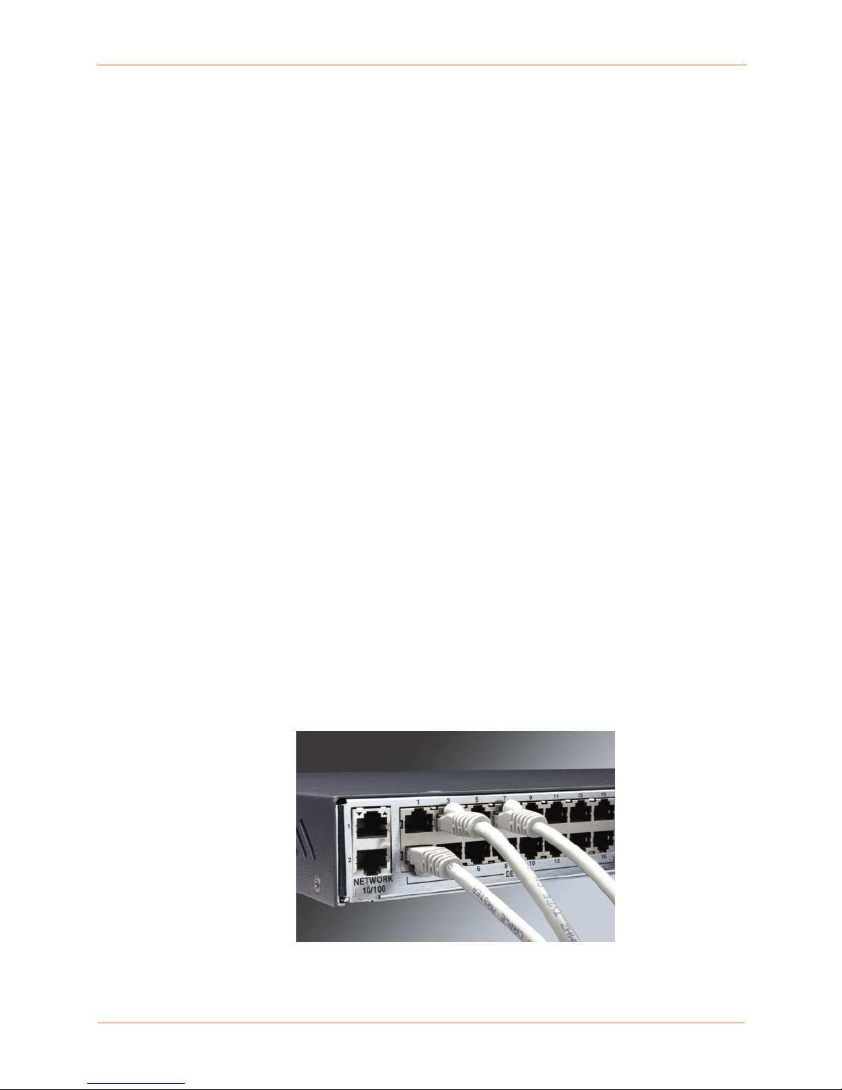
Figure 2-2. Device Port Connections
SecureLinx SLC User Guide 16
Page 17
2: Overview
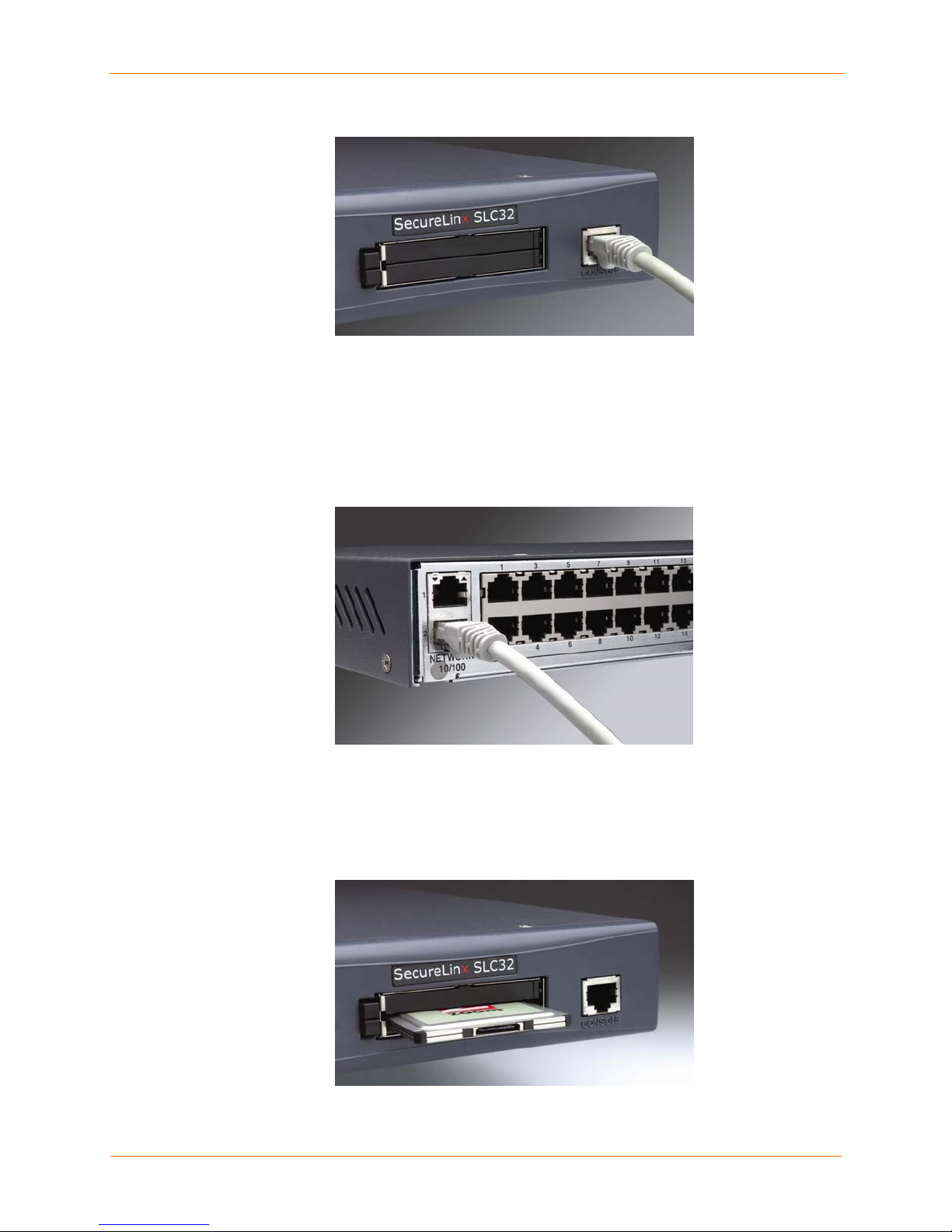
Figure 2-3. Console Port Connection
Network Connections
The SLC network interfaces are 10Base-T/100Base-TX connectors for use with a
conventional Ethernet network. Use standard RJ45-terminated Category 5 cables.
Network parameters must be configured before the SLC can be accessed over the
network.
Figure 2-4. Network Connection
PC Card Interface
The SLC has two PC Card slots. Lantronix qualifies cards continuously and publishes a
list of qualified cards on the Lantronix web site.
Figure 2-5. PC Card Interface
SecureLinx SLC User Guide 17
Page 18

33:: IInnssttaallllaattiioonn
This chapter provides a high-level procedure for installing the SLC followed by more
detailed information about the SLC connections and power supplies.
Caution: To avoid physical and electrical hazards, please be sure to read
B: Safety Information before installing the SLC.
What’s in the Box
In addition to the SLC, the box contains the following items:
Part # Component Description
Adapters:
200.2066A
200.2067A
200.2069A
200.2070A Adapter: DB9F (DCE) to RJ45, HP9000, SGI Origin, IBM RS6000, and
200.2225
Note: An optional adapter for external modems is also available from Lantronix: 200.2073
Adapter: DB25M (DCE) to RJ45, external modems.
Adapter: DB25M (DCE), Sun w/DB25 female
Adapter: DB25F (DCE) to RJ45, Sun w/DB25 male and some HP9000’s
Adapter: DB9M (DCE) to RJ45, SGI Onyx
PC-based Linux servers
Adapter: RJ45 to RJ45 rolled, Cisco, and Sun Netra
Cables:
200.0063
500-153
Power Cords:
500-041
083-011 For dual DC models: one accessory kit, containing DC plug connectors and
Documentation:
CD Case Quick Start Guide and CD_ROM containing the SecureLinx Console Manager
Cable: RJ45 to RJ45, 6.6 ft (2 m)
Cable: Loopback
For single AC models: one AC power cord
For dual AC models: two AC power cords
instructions
User Guide
Verify and inspect the contents of the SLC package using the enclosed packing slip or
the table above. If any item is missing or damaged, contact your place of purchase
immediately.
SecureLinx SLC User Guide 18
Page 19

Product Information Label
The product information label on the underside of the unit contains the following
information about each specific unit:
Part Number
Serial Number Bar Code
Serial Number and Date Code
Regulatory Certifications and Statements
Technical Specifications
Table 3-1. SLC Technical Specifications
3: Installation
Serial Interface
(Device)
Serial Interface
(Console)
Network Interface
Power Supply Universal AC power input: 100-240 VAC, 50 or 60 Hz
Power Consumption
Dimensions
Weight
Temperature
Relative Humidity
Heat Flow Rate 68 BTU per hour
RJ45-type 8-conductor connector (DTE)
Speed software selectable (300 to 115,200 baud)
RJ45-type 8-pin connector (DTE)
Speed software selectable (300 to 115,200 baud)
10Base-T/100Base-TX RJ45 Ethernet
IEC-type regional cord set included
DC power input :
-24 to -60 VDC
Less than 20 watts
1U, 1.75 in x 17.25 in x 12 in
10 lbs or less, depending on the options
Operating: 0 to 50 °C (32 to 122 °F), 30 to 90 %RH, non-condensing
Storage: -20 to 70 °C (-4 to 158 °F), 10 to 90 %RH, non-condensing
Operating: 10% to 90% non-condensing; 40% to 60% recommended
Storage: 10% to 90% non-condensing
You can install the SLC either in an EIA-standard 19-inch rack (1U tall) or as desktop
unit. The SLC uses convection cooling to dissipate excess heat.
SecureLinx SLC User Guide 19
Page 20

Physical Installation
To install the unit in a rack:
1. Place the unit in a 19-inch rack.
Warning: Be careful not to block the air vents on the sides of the unit. If
you mount the SLC in an enclosed rack, we recommended that the rack
have a ventilation fan to provide adequate airflow through the unit.
2. Connect the serial device(s) to the SLC device ports. See Connecting to a Device
Port on page 20.
3. Install any PC Cards you intend to use. If you install a modem card, connect to the
phone line. See 11: PC Card.
4. You have the following options:
a) To configure the SLC using the network, or to monitor serial devices on the
network, connect at least one SLC network port to a network. See Connecting
to a Network Port on page 21.
b) To configure the SLC using a dumb terminal or a computer with terminal
emulation, connect the terminal or PC to the SLC console port. See
Connecting a Terminal on page 21.
3: Installation
5. Connect the power cord, and apply power. See Power on page 22.
6. Wait approximately a minute and a half for the boot process to complete.
When the boot process ends, the SLC host name and the clock appear on the LCD
display.
Now you are ready to configure the network settings as described in 4: Quick Setup.
Connecting to a Device Port
You can connect any device that has a serial console port to a device port on the SLC for
remote administration. The console port must support the RS-232C interface.
Note: Many servers must either have the serial port enabled as a console or the
keyboard and mouse detached. Consult the server hardware and/or software
documentation for more information.
To connect to a device port:
1. Connect one end of the Cat 5 cable to the device port.
2. Connect the other end of the Cat 5 cable to a Lantronix serial console adapter.
Note: To connect a device port to a Lantronix SLP, use the rolled serial cable p rovided
with the unit, a 200.2225 adapter and Cat 5 cabling, or the ADP010104 adapter that
eliminates the need for an additional Cat5 patch cable between the adapter and the
connected equipment. See C: Adapters and Pinouts for more information about Lantronix
adapters.
3. Connect the adapter to the serial console of the serial device.
SecureLinx SLC User Guide 20
Page 21

3: Installation
Figure 3-1. CAT 5 Cable Connection
Connecting to a Network Port
The SLC’s network ports (10Base-T/100Base-TX) allow remote access to the attached
devices and the system administrative functions. Use a standard RJ45-terminated
Category 5 cable to connect to the network port.
Note: One possible use for the two Ethernet ports is to have one port on a
private, secure network, and the other on an unsecured network.
Connecting a Terminal
The console port is for local access to the SLC and the attached devices. You may attach
a dumb terminal or a computer with terminal emulation to the console port. The SLC
console port uses RS-232C protocol and supports VT100 em ulation. The default baud
rate is 9600.
To connect the console port to a terminal or computer with terminal emulation, Lantronix
offers optional adapters that provide a connection between an RJ45 jack and a DB9 or
DB25 connector. The console port is configured as DTE. For more information,
see C: Adapters and Pinouts and our web site at www.lantronix.com/support. and click
Cable/Adapter Lookup on the Support menu.
.
To connect a terminal:
1. Attach the Lantronix adapter to your terminal (use PN 200.2066A adapter) or your
PC's serial port (use PN 200.2070A adapter).
2. Connect the Cat 5 cable to the adapter, and connect the other end to the SLC
console port.
3. Turn on the terminal or start your computer’s communication program (e.g.,
HyperTerminal for Windows).
4. Once the SLC is running, press Enter to establish connection. You should see the
model name and a login prompt on your terminal. You are connected.
SecureLinx SLC User Guide 21
Page 22
3: Installation
Power
The SLC consumes less than 20W of electrical power.
AC Input
The SLC has a universal auto-switching AC power supply. The power supply accepts AC
input voltage between 100 and 240 VAC with a frequency of 50 or 60 Hz. Rear-mounted
IEC-type AC power connector(s) are provided for universal AC power input (North
American cord provided).
The SLC0xx12N models have a single supply/input, while the SLC0xx22N models have
dual inputs and dual supplies. The power connector also houses a repla ce able protective
fuse (fast-blow 4.0A, maximum 250V AC) and the on/off switch. In addition, we provide
the SLC0xx22N with a “Y” cord. (See SLC Models on page 13.)
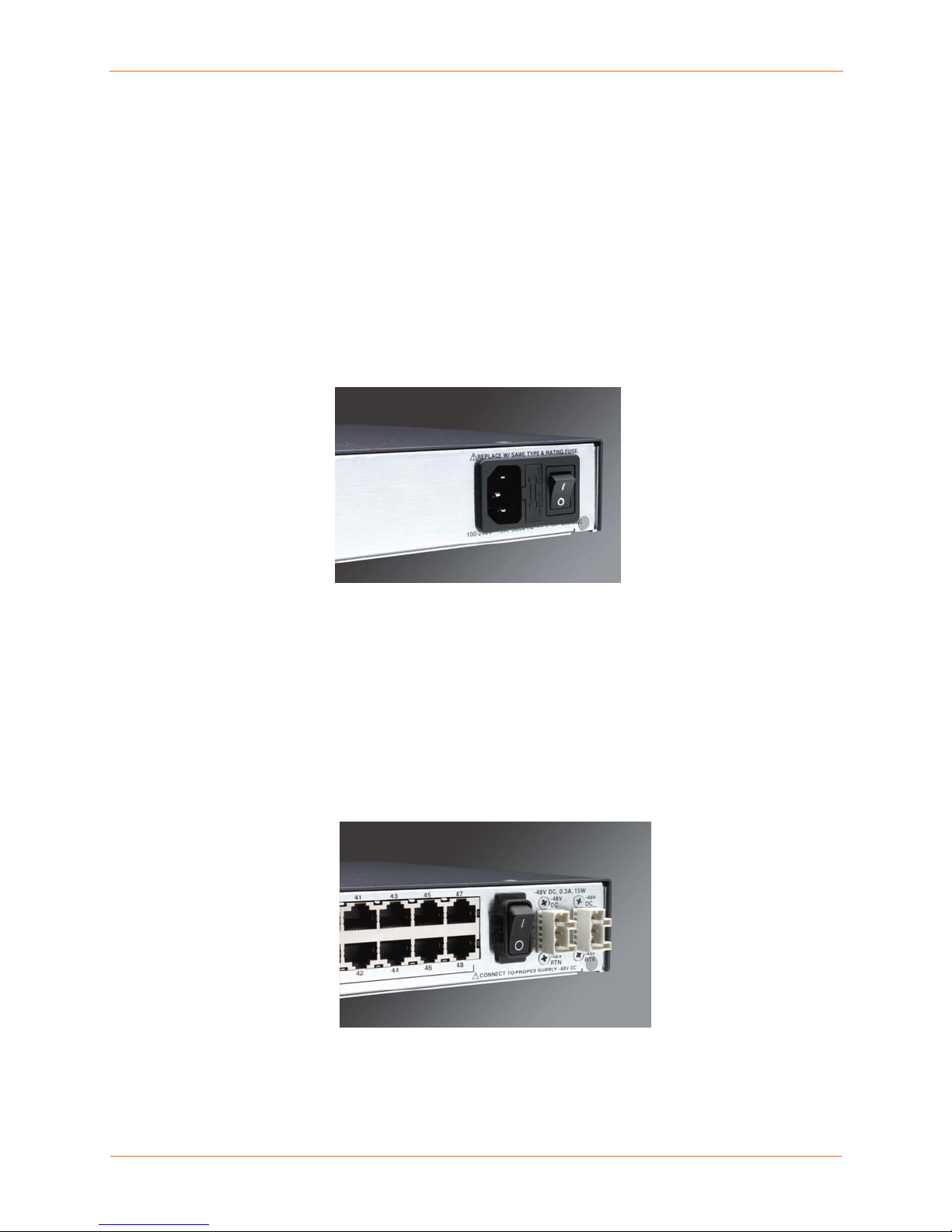
Figure 3-2. AC Power Input and Power Switch (SLCxxxx2N)
Note: The SLC48 with dual AC does not have an on/off switch.
DC Input
The DC version of the SLC accepts standard –48 VDC power. The SLC0xx24T models
accept two DC power inputs for supply redundancy. Lantronix provides the DC power
connections using industry standard Wago connectors. One set of connectors is included
with the SLC. You can order additional connectors (part number 721-103/031-0 00) from
the Wago catalog:
http://www.wagocatalog.com/okv3/index.asp?lid=1&cid=1&str_from_home=first
Figure 3-3. DC Power Inputs and Power Switch (SLCxxx24T)
SecureLinx SLC User Guide 22
Page 23

44:: QQuuiicckk SSeettuupp
This chapter helps get the IP network port up and running quickly, so you can administer
the SLC using your network. To set up the network connections quickly, we suggest you
do one of the following:
Use the front panel LCD display and pushbuttons.
Complete the Quick Setup web page on the web interface.
SSH to the command line interface and follow the Quick Setup script on the
command line interface.
Connect to the console port and follow the Quick Setup script on the command
line interface.
Note: The first time you power up the SLC, Eth1 tries to obtain its IP
address via DHCP. If you have connected Eth1 to the network, and Eth1 is
able to acquire an IP address, you can view this IP address on the LCD or
by running the Detector tool on the product CD. If Eth1 cannot acquire an IP
address, you cannot use Telnet, SSH, or the web interface to run Quick
Setup.
IP Address
Your SLC must have a unique IP address on your network. The system administrator
generally provides the IP address and corresponding subnet mask and gateway. The IP
address must be within a valid range, unique to your network, and in the same subnet as
your PC.
You have the following options for assigning an IP address to your unit.
Table 4-1. Methods of Assigning an IP Address
Method Description
DHCP
BOOTP
Detector™
A DHCP server automatically assigns the IP address and
network settings. The SLC is DHCP-enabled by default.
With the Eth1 network port connected to the network, and the
SLC powered up, Eth1 acquires an IP address, viewable on
the LCD.
At this point, you can Telnet into the SLC, or use the web
interface.
Similar to DHCP but for smaller networks.
A Windows-based application on the product CD for viewing a
DHCP-provided IP address or for assigning a static IP address
to the SLC. You can use Detector only if you have not already
assigned a static IP address by another method. For more
information, see Detector’s online help.
SecureLinx SLC User Guide 23
Page 24

Method Description
Front panel LCD display
and pushbuttons
You manually assign the IP address and other basic network,
console, and date/time settings. If desired, you can restore the
factory defaults.
4: Quick Setup
Serial port login to
command line interface
You assign an IP address and configure the SLC using a
terminal or a PC running a terminal emulation program to the
unit’s serial console port connection.
Method #1 Using the Front Panel Display
Before You Begin
Make sure you know:
An IP address that will be unique and valid on your network (unless automatically
assigned)
Subnet mask (unless automatically assigned)
Gateway
DNS settings
Date, time, and time zone
Console port settings: baud rate, data bits, stop bits, parity, and flow control
Make sure the SLC is plugged in to power and turned on.
Front Panel LCD Display and Pushbuttons
With the SLC powered up, you can use the front panel display and pushbuttons to set up
the basic parameters.
Figure 4-1. Front Panel LCD Display and Five Pushbuttons
(Enter, Up, Down, Left, Right)
The front panel display initially shows the host name and the date and time. Using the
five pushbuttons, you can change the network, console port, and date/time settings and
view the firmware release version. If desired, you can restore the factory defaults.
Note: Have your information handy as the display times out without accepting
any unsaved changes if you take more than 30 seconds betwee n entries.
SecureLinx SLC User Guide 24
Page 25
4: Quick Setup
Any changes made to the network, console port, and date/time settings take effect
immediately.
Navigating
The front panel has one Enter button (in the center) and four arrow buttons (up, left,
right, and down). Press the arrow buttons to navigate from one option to another, or to
increment or decrement a numerical entry of the selected option. Use the Enter button to
select an option to change or to save your settings.
Action Button
To move to the next option (e.g., from Network Settings to
Console Settings)
right arrow
up/down arrow
To return to the previous option
To enter edit mode
Within edit mode, to increase or decrease a numerical
entry
Within edit mode, to move the cursor right or left
To exit edit mode
To scroll up or down the list of parameters within an option
(e.g., from IP Address to Mask)
Table 4-2. Front Panel Setup Options with Associated Parameters
Normal Network
Settings
right/left arrow
Console
Settings
Date /
Time
Settings
Eth1 IP Address Time Zone
Eth1 Subnet Mask Date/Time
Gateway
DNS1
DNS2
DNS3
Baud Rate
Data Bits
Stop Bits
Parity
Flow Control
left arrow
Enter (center button)
up and down arrows
right or left arrows
Enter
up and down arrows
Release
Firmware version and
date code (display only)
Restore Factory
Defaults
Entering the Settings
To enter setup information:
1. From the normal display (host name, date and time), press the right arrow button
to display Network Settings. The IP address for Eth1 displays.
SecureLinx SLC User Guide 25
Page 26

4: Quick Setup
Note: If you have connected Eth1 to the network, and Eth1 is able to acquire
an IP address through DHCP, this IP address displays, followed by the letter
[D]. Otherwise, the IP address displays as all zeros (000.000.000.000).
2. Press the Enter button on the keypad to enter edit mode. A cursor displays below
one character of the existing IP address setting.
3. To enter values:
Use the left or right arrow to move the cursor to the left or to the right position.
Use the up or down arrow to increment or decrement the numerical value.
4. When you have the IP address as you want it, press Enter to exit edit mode, and
then press the down arrow button. The Subnet Mask parameter displays.
Note: You must edit the IP address and the Subnet Mask together for a valid
IP address combination.
5. To save your entries for one or more parameters in the group, press the right
arrow button. The Save Settings? Yes/No prompt displays.
Note: If the prompt does not display, make sure you are no longer in edit
mode.
6. Use the left/right arrow buttons to select Yes, and press the Enter button.
7. Press the right arrow button to move to the next option, Console Settings.
8. Repeat steps 2-7 for each setting.
9. Press the right arrow button to move to the next option, Date/Time Settings, and
click Enter to edit the time zone.
a) To enter a US time zone, use the up/down arrow buttons to scroll through the
US time zones, and then press Enter to select the correct one.
b) To enter a time zone outside the US, press the left arrow button to move up to
the top level of time zones. Press the up/down arrow button to scroll
through the top level.
A time zone with a trailing slash (such as Africa/) has sub-time zones. Use the
right arrow button to select the Africa time zones, and then the up/down
arrows to scroll through them.
Press Enter to select the correct time zone. To move back to the top-level time
zone at any time, press the left arrow.
10. To save your entries, press the right arrow button. The Save Settings? Yes/No
prompt displays.
Note: If the prompt does not display, make sure you are no longer in edit
mode.
11. Use the left/right arrow buttons to select Yes, and press the Enter button.
12. To review the saved settings, press the up or down arrows to step through the
current settings.
When you are done, the front panel returns to the clock display. The network port
resets to the new settings, and you can connect to your IP network for further
administration. You should be able to Telnet or SSH to the SLC through your network
connection, or access the web interface through a web browser.
SecureLinx SLC User Guide 26
Page 27

Restoring Factory Defaults
To use the LCD display to restore factory default settings:
1. Press the right arrow button to move to the last option, Release.
2. Use the down arrow to move to the Restore Factory Defaults option. A prompt
for the 6-digit Restore Factory Defaults password displays.
3. Press Enter to enter edit mode.
4. Using the left and right arrows to move between digits and the up and down
arrows to change digits, enter the password (the default password is 999999).
Note: The Restore Factory Defaults password is only for the LCD. You can change
it at the command line interface using the admin keypad password command.
5. Press Enter to exit edit mode. If the password is valid, a Save Settings? Yes/No
prompt displays.
6. To initiate the process for restoring factory defaults, select Yes. When the process
is complete, the SLC reboots.
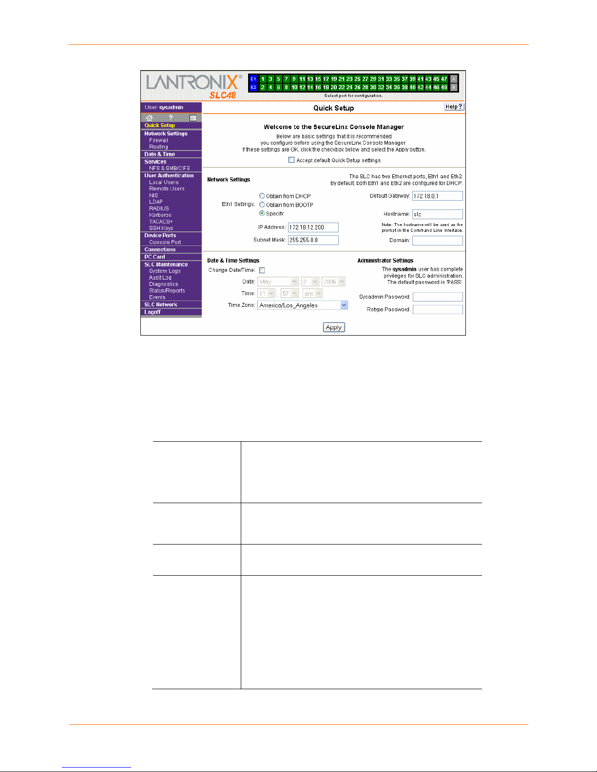
Method #2 Quick Setup on the Web Page
4: Quick Setup
After the unit has an IP address, you can use the Quick Setup web page to configure the
remaining network settings. This page displays the first time you log into the SLC only.
Otherwise, the SLC Home Page displays. (For information about the web interface, see
Web Interface on page 33.)
To complete the Quick Setup page:
1. Open a web browser (Netscape Navigator 6.x and above or Internet Explorer 5.5.
and above, with JavaScript enabled).
2. In the URL field, type https:// followed by the IP address of your SLC.
3. Log in using sysadmin as the user name and PASS as the password. The first
time you log in to the SLC, the Quick Setup page automatically displays.
Otherwise, the Home page displays.
Note: To open the Quick Setup page at another time, click Quick Setup on the main
menu on the left.
SecureLinx SLC User Guide 27
Page 28
4: Quick Setup
4. To accept the defaults, select the Accept default Quick Setup settings checkbox
in the top portion of the page and click Apply at the bottom of the page. Otherwise,
continue with step 5.
Note: Once you click Apply on the Quick Setup page , you can continue
using the web interface to configure the SLC further.
5. Enter the following:
Network Settings
Obtain from
DHCP
Obtain from
BOOTP
Specify
IP Address (if
specifying)
Acquires IP address, subnet mask, and gateway from the
DHCP server. (The DHCP server may not provide the
gateway, depending on its setup.) By default, both Eth1
and Eth2 are enabled. If you select DHCP, skip to Default
Gateway.
Lets a network node request configuration
information from a BOOTP "server" node. If you
select this option, skip to Default Gateway.
Lets you manually assign a static IP address, generally
provided by the system administrator.
Enter an IP address that will be unique and valid on your
network. There is no default.
Enter all IP addresses in dot-quad notation. Do not use
leading zeros in the fields for dot-quad numbers less than
100. For example, if your IP address is 172.19.201.28, do
not enter 028 for the last segment.
Note: Currently, the SLC does not support configurations
with the same IP subnet on multiple interfaces (Ethernet or
PPP).
SecureLinx SLC User Guide 28
Page 29

4: Quick Setup
Subnet Mask
Default Gateway
Hostname The default host name is slc. There is a 64-character limit
Domain
If specifying an IP address, enter the subnet mask
specifying the network segment on which the SLC resides.
There is no default.
The IP address of the router for this network. There is no
default.
(contiguous characters, no spaces).
Note: The host name becomes the prompt in the
command line interface.
If desired, specify a domain name (for example,
support.lantronix.com).
Date & Time Settings
Change
Date/Time
Date
Time
Time Zone
Select the checkbox to manually enter the date and time at
the SLC’s location.
From the drop-down lists, select the current month, day,
and year.
From the drop-down lists, select the current hour and
minute.
From the drop-down list, select the appropriate time zone.
Administrator Settings
Sysadmin
Password/
Retype
Password
6. To save your entries, click Apply.
To change the password (e.g., from the default) enter a
password of up to 64 characters.
SecureLinx SLC User Guide 29
Page 30

4: Quick Setup
Method #3 Quick Setup on the Command Line Interface
If the SLC does not have an IP address, you can connect a dumb terminal or a PC
running a terminal emulation program (VT100) to access the command line interface.
(See Connecting a Terminal on page 21.) If the unit has an IP address, you can use SSH
or Telnet to connect to the SLC.
Note: By default, Telnet is disabled and SSH is enabled. To enable Telnet, use the
Services web page (see 7: Services), a serial terminal connection, or an SSH connection.
To complete the command line interface Quick Setup script:
1. Do one of the following:
With a serial terminal connection, power up, and when the command line
displays, press Enter.
With a network connection, use an SSH program or Telnet program (if Telnet has
been enabled) to connect to xx.xx.xx.xx (the IP address in dot quad notation),
and press Enter. You should be at the login prompt.
2. Enter sysadmin as the user name and press Enter.
3. Enter PASS as the password and press Enter. The first time you log in, the Quick
Setup script runs automatically. Normally, the command prompt displays.
Figure 4-2. Beginning of Quick Setup Script
Welcome to the SecureLinx Console Manager
Model Number: SLC48
Quick Setup will now step you through configuring a few basic settings.
The current settings are shown in brackets ('[]').
You can accept the current setting for each question by pressing <return>.
4. Enter the following information at the prompts:
Note: To accept a default or to skip an entry that is not required, press
Enter.
Configure Eth1
Select one of the following:
<1> obtain IP Address from DHCP: The unit will acquire
the IP address and gateway from the DHCP server. (The
DHCP server may or may not provide the gateway,
depending on its setup.) This is the default setting.
<2> obtain IP Address from BOOTP: Permits a
network node to request configuration information
from a BOOTP "server" node.
<3> static IP Address: Allows you to assign a static IP
address manually. The IP address is generally provided by
the system administrator.
SecureLinx SLC User Guide 30
Page 31

4: Quick Setup
IP Address (if
specifying)
Subnet Mask
Default Gateway
Hostname The default host name is slc. There is a 64-character limit
Domain
An IP address that will be unique and valid on your
network and in the same subnet as your PC. There is no
default.
If you selected DHCP or BOOTP, this prompt does not
display.
Enter all IP addresses in dot-quad notation. Do not use
leading zeros in the fields for dot-quad numbers less than
100. For example, if your IP address is 172.19.201.28, do
not enter 028 for the last segment.
Note: Configurations with the same IP subnet on multiple
interfaces (Ethernet or PPP) are not currently supported.
The subnet mask specifies the network segment on which
the SLC resides. There is no default. If you selected DHCP
or BOOTP, this prompt does not display.
IP address of the router for this network. There is no
default.
(contiguous characters, no spaces).
Note: The host name becomes the prompt in the
command line interface.
If desired, specify a domain name (for example,
support.lantronix.com). The domain name is used for host
name resolution within the SLC. For example, if abcd is
specified for the SMTP server, and mydomain.com is
specified for the domain, if abcd cannot be resolved, the
SLC attempts to resolve abcd.mydomain.com for the
SMTP server.
Time Zone
Date/Time If the date and time displayed are correct, type n and
Sysadmin
password
If the time zone displayed is incorrect, enter the correct
time zone and press Enter. If the entry is not a valid time
zone, the system guides you through selecting a time
zone. A list of valid regions and countries displays. At the
prompts, enter the correct region and country.
continue. If the date and time are incorrect, type y and
enter the correct date and time in the formats shown at the
prompts.
Enter a new sysadmin password.
After you complete the Quick Setup script, the changes take effect immediately.
SecureLinx SLC User Guide 31
Page 32

4: Quick Setup
Figure 4-3. Completed Quick Setup
5. To logout, type logout at the prompt and press Enter.
Next Step
After quick starting the SLC, you may want to configure other settings. You can use the
web page or the command line interface for configuration.
For information about the web and the command line interfaces, go to
To continue configuring the SLC, go to 6: Basic Parameters.
5: Web and Command Line Interfaces.
SecureLinx SLC User Guide 32
Page 33

55:: WWeebb aanndd CCoommmmaanndd LLiinnee IInntteerrffaacceess
The SLC offers three interfaces for configuring the SLC: a command line interface (CLI),
a web interface, and an LCD with pushbuttons on the front panel. This chapter discusses
the web and command line interfaces. (4: Quick Setup includes instructions for using the
LCD to configure basic network settings.)
Web Interface
A web interface allows the system administrator and other authorized users to configure
and manage the SLC using most web browsers (Netscape Navigator 6.x and above or
Internet Explorer 5.5. and above, with JavaScript enabled). The Web Telnet and Web
SSH features require Java 1.1 (or later) support in the browser. The SLC provides a
secure, encrypted web interface over SSL (secure sockets layer).
The following figure shows a typical web page:
SecureLinx SLC User Guide 33
Page 34

Icons
Main
Menu
5: Web and Command Line Interfaces
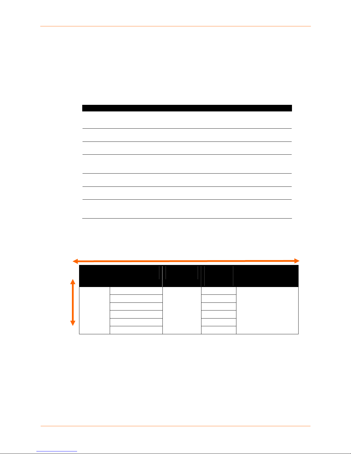
Figure 5-1. Web Page Layout
Port Number
Bar
Help Button
Entry Fields
and Options
Apply Button
The web page has the following components:
Main Menu: Allows you to select the type of setting to configure.
Note: The SLC displays a customized navigation menu based on the currently logged-in
user's rights.
Port Number Bar: Allows you to select a port and display its settings. The E1 and E2
buttons display the Network – Settings page. The A and B buttons display the status of
the power supplies.
Note: Only ports to which the currently logged-in user has rights ar e enabled.
Entry Fields and Options: Allow you to enter data and select options for the settings.
Note: For specific instructions on completing the fields on the web pages, se e
Chapters 6 through 12.
Apply Button: Apply on each web page makes the change s immediately and saves
them so they will be there when the SLC is rebooted.
Icons: The icons above the Main Menu
:
SecureLinx SLC User Guide 34
Page 35

5: Web and Command Line Interfaces
Display the Home page.
Display information about the SLC and Lantronix contact information.
Show the status of the SLC.
Help Button: Provides online Help for the specific web page.
Logging in
Only the system administrator or users with web access rights can log into the web page.
More than one user at a time can log in, but the same user cannot login more than once.
To log in to the SLC web interface:
1. Open a web browser (Netscape Navigator 6.x and above or Internet Explorer 5.5.
and above).
2. In the URL field, type https:// followed by the IP address of your SLC.
3. To configure the SLC, use sysadmin as the user name and PASS as the
password. (These are the default values.)
Note: The system administrator may have changed the password using one
of the Quick Setup methods in the previous chapter.
The Lantronix SLC Quick Setup page displays automatically the first time you log in.
Subsequently, the Lantronix SLC Home page displays. (If you want to display the
Quick Setup page again, click Quick Setup on the main menu.)
Logging off
To log off the SLC web interface:
From the main menu, select Logoff. The “SLC logoff complete” message displays.
SecureLinx SLC User Guide 35
Page 36

Web Page Help
To view detailed information about an SLC web page:
Click the Help button to the right of the web page title.
Command Line Interface
A command line interface (CLI) is available for entering all the commands you can use
with the SLC. In this User Guide, after each section of instructions for using the web
interface, you will find the equivalent CLI commands. You can access the command line
interface using Telnet, SSH, or a serial terminal connection.
Note: By default, Telnet is disabled and SSH is enabled. To enable Telnet, use the
Services web page, a serial terminal connection, or an SSH connection.
(See 7: Services.)
The sysadmin user and users with who have full administrative rights have access to the
complete command set, while all other users have access to a reduced command set
based on their permissions.
5: Web and Command Line Interfaces
Logging in
To log in to the SLC command line interface:
1. Do one of the following:
With a serial terminal connection, power up, and when the command line
displays, press Enter.
If the SLC already has an IP address (assigned previously or assigned by
DHCP), Telnet (if Telnet has been enabled) or SSH to xx.xx.xx.xx (the IP
address in dot quad notation) and press Enter. The login prompt displays.
2. To log in as the system administrator for setup and configuration:
a) Enter sysadmin as the user name and press Enter.
b) Enter PASS as the password and press Enter. The first time you log in, the
Quick Setup script runs automatically. Normally, the command prompt
displays. (If you want to display the Quick Setup script again, use the admin
quicksetup command.)
Note: The system administrator may have changed the password using
one of the Quick Setup methods in the previous chapter.
3. To log in any other user:
a) Enter your SLC user name and press Enter.
b) Enter your SLC password and press Enter.
Logging out
To log out of the SLC command line interface:
To log out, type logout and press Enter.
SecureLinx SLC User Guide 36
Page 37

5: Web and Command Line Interfaces
Command Syntax
Commands have the following format:
<action> <category> <parameter(s)>
where
<action> is set, show, connect, admin, diag, pccard, or logout.
<category> is a group of related parameters whose settings you want to configure or
view. Examples are ntp, deviceport, and network.
<parameter(s)> is one or more name-value pairs in one of the following formats:
<parameter name> <aa⏐bb>
User must specify one of the values (aa
or bb) separated by a vertical line ( | ).
The values are in all lowercase and must
be entered exactly as shown. Bold
indicates a default value.
<parameter name> <Value>
User must specify an appropriate value,
for example, an IP address. The
parameter values are in mixed case.
Square brackets [ ] indicate optional
parameters.
Table 5-1. Actions and Category Options
Action Category
set network | firewall | routing | datetime | ntp | services |
nfs | cifs | menu | auth | localusers | remoteusers | ldap
| radius | kerberos | tacacs | consoleport | deviceport |
nis |locallog | slcnetwork | command | sshkey | password |
history | cli | command |
show network | firewall | routing | datetime | ntp | services |
nfs | cifs | menu | auth | localusers | nis | ldap | radius
| kerberos | tacacs | consoleport | deviceport | locallog |
sysstatus| syslog | auditlog | portstatus | sysconfig |
portcounters | connections | slcnetwork | sshkey | history
| cli | user | slcnetwork
connect direct | listen | bidirection | unidirection | terminate
diag ping | loopback | traceroute | arp | lookup | netstat |
perfstat | sendpacket | nettrace
pccard storage | modem
admin reboot | shutdown | ftp | config | firmware | version |
banner | keypad | quicksetup | web | events
logout
Terminates CLI session.
SecureLinx SLC User Guide 37
Page 38

5: Web and Command Line Interfaces
Command Line Help
For general Help and to display the commands to which you have rights, type:
help
For general command line Help, type:
help command line
For more information about a specific command, type help followed by the command,
for example:
help set network or help admin firmware
Tips
Type enough characters to uniquely identify the action, category, or parameter
name. For parameter values, type the entire value. For example, you can
shorten:
set network port 1 state static ipaddr 122.3.10.1 mask
255.255.0.0
to
se net po 1 st static ip 122.3.10.1 ma 255.255.0.0
Use the Tab key to automatically complete action, category, or parameter
names. Type a partial name and press Tab either to complete the name if only
one is possible, or to display the possible names if more than one is possible.
Following a space after the preceding name, Tab displays all possible names.
Should you make a mistake while typing, backspace by pressing the Backspace
key and/or the Delete key, depending on how you accessed the interface. Both
keys work if you use VT100 emulation in your terminal access program when
connecting to the console port. Use the left and right arrow keys to move within
a command.
Use the up and down arrows to scroll through previously entered commands. If
desired, select one and edit it. You can scroll through up to 100 previous
commands entered in the session.
To clear an IP address, type 0.0.0.0, or to clear a non-IP address value, type
CLEAR.
When the number of lines displayed by a command exceeds the size of the window (the
default is 25), the command output is halted until the user is ready to continue. To display
the next line, press Enter, and to display the page, press the space bar. You can override
the number of lines (or disable the feature altogether) with the set cli command.
SecureLinx SLC User Guide 38
Page 39

5: Web and Command Line Interfaces
General CLI Commands
The following commands relate to the CLI itself.
To configure the current command line session:
set cli scscommands <enable|disable>
Allows you to use SCS-compatible commands as shortcuts for executin g commands:
SCS Commands SLC Commands
info 'show sysstatus'
version 'admin version'
reboot 'admin reboot'
poweroff 'admin shutdown'
listdev 'show deviceport names'
direct 'connect direct deviceport'
listen 'connect listen deviceport'
clear 'set locallog clear'
telnet 'connect direct telnet'
ssh 'connect direct ssh'
To set the number of lines displayed by a command:
set cli terminallines <disable|Number of lines>
Sets the number of lines in the terminal emulation (screen) for paging through text one
screenful at a time, if the SLC cannot detect the size of the terminal automatically.
To show current CLI settings:
show cli
To view the last 100 commands entered in the session:
show history
To clear the command history:
set history clear
To view the rights of the currently logged-in user:
show user
Note: For information about user rights, see 10: User Authentication.
SecureLinx SLC User Guide 39
Page 40

66:: BBaassiicc PPaarraammeetteerrss
This chapter explains how to set the following basic configuration settings for the SLC
using the SLC web interface or the CLI:
Network parameters that determine how the SLC interacts with the attached
network
Firewall and routing
Date and time
Note: If you entered some of these settings using a Quick Setup procedure, you
may update them here.
Requirements
If you assign a different IP address from the current one, it must be within a valid range,
unique to your network, and with the same subnet mask as your workstation.
To configure the unit, you need the following information:
Eth1
Eth2
IP address: ________. ________ . ________ .________
Subnet mask: ________ . ________ . ________ .________
IP address (optional): ________ . ________ . ________ .________
Subnet mask (optional): ________ . ________ . ________ .________
Gateway: ________ . ________ . ________ .________
DNS: ________ . ________ . ________ .________
SecureLinx SLC User Guide 40
Page 41

Network Port(s)
To enter settings for one or both network ports:
1. From the main menu, select Network Settings. The following page displays:
6: Basic Parameters
2. Enter the following information for one or both network ports (Eth1 and Eth2).
Eth1 and Eth2 Settings
Note: Configurations with the same IP subnet on multiple interfaces (Ethernet or
PPP) are not currently supported.
Disabled
SecureLinx SLC User Guide 41
If selected, disables the network port. Defaults are Eth1
and Eth2 enabled.
Page 42

6: Basic Parameters
Obtain from DHCP
Obtain from
BOOTP
Specify
IP Address (if
specifying)
Subnet Mask
Eth1 and Eth2
Mode
Acquires IP address, subnet mask, and gateway from the
DHCP server. (The DHCP server may not provide the
gateway, depending on its setup.) This is the default
setting. If you select this option, skip to step 4.
Lets a network node request configuration
information from a BOOTP "server" node. If you
select this option, skip to step 4.
Lets you manually assign a static IP address, generally
provided by the system administrator.
Enter an IP address that will be unique and valid on your
network. There is no default.
Enter all IP addresses in dot-quad notation. Do not use
leading zeros in the fields for dot-quad numbers less than
100. For example, if your IP address is 172.19.201.28, do
not enter 028 for the last segment.
Note: Currently, the SLC does not support configurations
with the same IP subnet on multiple interfaces (Ethernet or
PPP).
If specifying an IP address, enter the network segment on
which the SLC resides. There is no default.
Select the direction (full-duplex or half-duplex) and speed
(10 or 100Mbit) of data transmission. The default is Auto,
which allows the Ethernet port to auto-negotiate the speed
and duplex with the hardware endpoint to which it is
connected.
3. Enter the following:
Gateways and Hostname
Default Gateway
DHCP Gateway
Precedence
IP address of the router for this network.
If this has not been set manually, any gateway acquired by
DHCP for Eth1 or Eth2 displays.
All network traffic that matches the Eth1 IP address and
subnet mask is sent out Eth1. All network traffic that
matches the Eth2 IP address and subnet mask is sent out
Eth 2.
If you set a default gateway, any network traffic that does
not match Eth1 or Eth2 is sent to the default gateway for
routing.
Gateway acquired by DHCP for Eth1 or Eth2.
Indicates whether the gateway acquired by DHCP or the
default gateway takes precedence. The default is DHCP
Gateway. If the DHCP Gateway is selected and both Eth1
and Eth2 are configured for DHCP, the SLC gives
precedence to the Eth1 gateway.
SecureLinx SLC User Guide 42
Page 43

6: Basic Parameters
Hostname The default host name is slc. There is a 64-character limit
(contiguous characters, no spaces).
Note: The host name becomes the prompt in the
command line interface.
Domain
Enable IP
Forwarding
If desired, specify a domain name (for example,
support.lantronix.com). The domain name is used for host
name resolution within the SLC. For example, if abcd is
specified for the SMTP server, and mydomain.com is
specified for the domain, if abcd cannot be resolved, the
SLC attempts to resolve abcd.mydomain.com for the
SMTP server.
IP forwarding enables network traffic received on one
interface (Eth1, Eth2, or an external/PC Card modem
attached to the SLC with an active PPP connection) to be
transferred out another interface (any of the above). The
default behavior (if IP forwarding is disabled) is for network
traffic to be received but not routed to another destination.
Enabling IP forwarding is required if you enable Network
Address Translation (NAT) for any device port modem or
PC Card/ISDN modem. IP forwarding allows a user
accessing the SLC over a modem to access the network
connected to Eth1 or Eth2.
4. Configure up to three name servers. The first three DNS servers acquired via
DHCP through Eth1 and/or Eth2 display automatically.
DNS Servers
#1
IP address of the primary name server. This entry is
required if you choose to configure DNS (Domain Name
Server) servers.
#2 (optional)
#3 (optional)
IP address of the second DNS name server.
IP address of the third DNS name server.
DHCP-Acquired DNS Servers
#1
#2
#3
Displays the IP address of the primary name server if
automatically assigned by DHCP
Displays the IP address of the second DNS server if
assigned by DHCP.
Displays the IP address of the third DNS server if assigned
by DHCP.
GPRS-Acquired DNS Servers
#1
#2
#3
Displays the IP address of the primary name server if
automatically assigned by General Packet Radio Service
(GPRS).
Displays the IP address of the second DNS server if
assigned by GPRS.
Displays the IP address of the third DNS server if assigned
by GPRS.
SecureLinx SLC User Guide 43
Page 44

5. Enter the following:
TCP Keepalive Parameters
6: Basic Parameters
Start Probes
Number of Probes
Interval
Number of seconds the SLC waits after the last
transmission before sending the first probe to determine
whether a TCP session is still alive. The default is 600
seconds (10 minutes).
Number of probes the SLC sends before closing a session.
The default is 5.
The number of seconds the SLC waits between probes.
The default is 60 seconds.
6. To save your entries, click Apply. Apply makes the changes immediately and
saves them so they will be there when the SLC is rebooted.
Ethernet Counters
The Network-Settings page displays statistics for each of the SLC’s Ethernet ports since
boot-up. The system automatically updates them.
Note: For Ethernet statistics for a smaller time period, use the diag perfstat
command.
Network Commands
The following CLI commands correspond to the web page entries described above.
To configure Ethernet port 1 or 2:
set network port <1|2> <parameters>
Parameters:
mode <auto|10mbit-half|100mbit-half|
10mbit-full|100mbit-full>
state <dhcp|bootp|static|disable>
[ipaddr <IP Address> mask <Mask>]
To configure up to three DNS servers:
set network dns <1|2|3> ipaddr <IP Address>
SecureLinx SLC User Guide 44
Page 45

To set the default gateway:
set network gateway <parameters>
Parameters:
default <IP Address>
precedence <dhcp|default>
To set the SLC host name and domain name:
set network host <Hostname> [domain <Domain Name>]
To set TCP Keepalive and IP Forwarding network parameters:
set network <parameters>
Parameters:
interval <1-99999 Seconds>
ipforwarding <enable|disable>
probes <Number of Probes>
startprobes <1-99999 Seconds>
6: Basic Parameters
To view all network settings:
show network all
To view Ethernet port settings and counters:
show network port <1|2>
To view DNS settings:
show network dns
To view gateway settings:
show network gateway
To view the host name of the SLC:
show network host
Firewall
With the SLC, you have the option of enabling packet filtering (a “firewall”). By default, the
option is disabled.
To configure firewall settings:
1. From the main menu, select Network Settings-Firewall. The following page
displays:
SecureLinx SLC User Guide 45
Page 46

2. Enter the following:
6: Basic Parameters
Enable Firewall
Reject Method
Invisible to ping
Ports to allow
3. To save, click Apply.
Select the checkbox to enable packet filtering. Disabled by
default.
Method of rejecting attempts to access your SLC. Select
one of the following options:
To deny an attempt, select Reply with ‘connection
denied’ on denied ports (default).
To ignore an attempt without sending a response, select
Ignore connection attempts on denied ports.
Select the checkbox to enable the SLC to be invisible to
ping or traceroute inquiries. Enabled by default.
Applies to both network ports. To cause the firewall to allow
specific types of ports to be open, select the appropriate
checkboxes. SSH and HTTPS are the defaults.
SecureLinx SLC User Guide 46
Page 47

Firewall Commands
The following CLI commands correspond to the web page entries described above.
To configure packet filtering for incoming network traffic:
set firewall <one or more parameters>
Parameters:
allowport <http|https|smbcifs|ssh|telnet>
denyport <http|https|smbcifs|ssh|telnet>
invisibletoping <enable|disable>
rejectmethod <reply|ignore>
state <enable|disable>
To view firewall settings:
show firewall
6: Basic Parameters
Routing
The SLC allows you to define static routes and, for networks using Routing Information
Protocol (RIP)-capable routes, to enable the RIP protocol to configure the routes
dynamically.
To configure routing settings:
1. From the main menu, select Network Settings-Routing. The following page
displays:
SecureLinx SLC User Guide 47
Page 48

6: Basic Parameters
2. Enter the following:
Dynamic Routing
Enable RIP
RIP Version Select the RIP version. The default is 2.
Select to enable Dynamic Routing Information Protocol
(RIP) to assign routes automatically. Disabled by default.
Static Routing
Enable Static
Routing
Select to assign the routes manually. The system
administrator usually provides the routes. Disabled by
default.
To add a static route, enter the IP Address, Subnet
Mask, and Gateway for the route and click the
Add/Edit Route button. The route displays in the Static
Routes table. You can add up to 64 static routes.
To edit a static route, select the radio button to the right
of the route, change the IP Address, Subnet Mask,
and Gateway fields as desired, and click the Add/Edit
Route button.
To delete a static route, select the radio button to the
right of the route and click the Delete Route button.
3. Click Apply.
Note: To display the routing table, click the IP Routes Report link. The
Status/Reports page displays. To view the report, select the IP Routes checkbox and
click Generate Report.
SecureLinx SLC User Guide 48
Page 49

6: Basic Parameters
Equivalent Routing Commands
The following CLI commands correspond to the web page entries described above.
To configure static or dynamic routing:
set routing [parameters]
Parameters:
rip <enable|disable>
route <1-64> ipaddr <IP Address> mask <Netmask>
gateway <IP Address>
static <enable|disable>
version <1|2|both>
Note: To delete a static route, set the IP address, mask, and gateway parameters to 0.0.0.0.
To set the routing table to display IP addresses (disable) or the corresponding host
names (enable):
show routing [resolveip <enable|disable>] [email
Note: You can optionally email the displayed information.
<Email Address>]
Date and Time
You can specify the current date, time, and time zone at the SLC’s location (default), or
the SLC can use NTP to synchronize with other NTP devices on your network.
To set the local date, time, and time zone:
1. From the main menu, select Date & Time. The following page displays:
SecureLinx SLC User Guide 49
Page 50

2. Enter the following:
6: Basic Parameters
Change
Date/Time
Date
Time
Time Zone
Select the checkbox to manually enter the date and time at
the SLC’s location.
From the drop-down lists, select the current month, day,
and year.
From the drop-down lists, select the current hour and
minute.
From the drop-down list, select the appropriate time zone.
3. To save, click Apply.
To synchronize the SLC with a remote time server using NTP:
1. Enter the following:
Enable NTP
Synchronize via
Select the checkbox to enable NTP synchronization.
NTP is disabled by default.
Select one of the following:
Broadcast from NTP Server: Enables the SLC to
accept time information periodically transmitted by
the NTP server. This is the default if you enable
NTP.
Poll NTP Server: Enables the SLC to query the NTP
Server for the correct time. If you select this option,
complete one of the following:
Local: Select this option if the NTP servers are
on a local network, and enter the IP address of
up to three NTP servers. This is the default, and
it is highly recommended.
Public: Select this option if you want to use a
public NTP server, and select the address of the
NTP server from the drop-down list. This is not
recommended because of the high load on many
public NTP servers. All servers in the drop-down
list are stratum-2 servers. (See www.ntp.org for
more information.)
Each public NTP server has its own usage rules -
-please refer to the appropriate web site before
using one. Our listing them here is to provide
easy configuration but does not indicate any
permission for use.
2. To save, click Apply.
SecureLinx SLC User Guide 50
Page 51

6: Basic Parameters
Date and Time Commands
The following CLI commands correspond to the web page entries described above.
To set the local date, time, and local time zone (one parameter at a time):
set datetime <one date/time parameter>
Parameters:
date <MMDDYYhhmm[ss]>
timezone <Time Zone>
Note: If you type an invalid time zone, the system guides you through the
process of selecting a time zone.
To view the local date, time, and time zone:
show datetime
To synchronize the SLC with a remote time server using NTP:
set ntp <one or more ntp parameters>
Parameters:
localserver1 <IP Address or Hostname>
localserver2 <IP Address or Hostname>
localserver3 <IP Address or Hostname>
poll <local|public>
publicserver <IP Address or Hostname>
state <enable|disable>
sync <broadcast|poll>
To view NTP settings:
show ntp
SecureLinx SLC User Guide 51
Page 52

77:: SSeerrvviicceess
System Logging and Other Services
Use the Services page to:
Configure the amount of data sent to the logs
Enable or disable SSH and Telnet logins
Enable a Simple Network Management Protocol (SNMP) agent
Note: The SLC supports both MIB-II (as defined by RFC 1213) and a private
enterprise MIB. The SLC product CD includes the MIB definition files for the private
enterprise MIB. The private enterprise MIB provides read-only access to all statistics
and configurable items provided by the SLC. It provides read-write access to a select
set of functions for controlling device ports (zeroing device port counters, clearing the
local log, and terminating all connections associated with a device port). See the MIB
definition file for details.
Identify a Simple Mail Transfer Protocol (SMTP) server
Configure an audit log
To configure services:
1. In the main menu, select Services. The following page displays.
SecureLinx SLC User Guide 52
Page 53

7: Services
2. In the System Logging section, select one of the following alert levels from the
drop-down list for each message category:
Off: Disables this type of logging.
Info: Saves informative message, in addition to warning and error messages.
Warning: Saves message output from a condition that may be cause for concern,
in addition to error messages. This is the default for all message types.
Error: Saves messages that are output because of an error.
Debug: Saves extraneous detail that may be helpful in tracking down a problem,
in addition to information, warning, and error messages.
Network
Services
Authentication
Device Ports
Messages concerning the network activity, for example
about Ethernet and routing.
Messages concerning services such as SNMP and
SMTP.
Messages concerning user authentication.
Messages concerning device ports and connections.
SecureLinx SLC User Guide 53
Page 54

7: Services
Diagnostics
General
Remote Syslog
Servers (#1 and #2)
Enable Audit Log
Audit Log Size The log has a default maximum size of 50 Kbytes
Include CLI
Commands
Include In System
Log
Messages concerning system status and problems.
Any message not in the categories above.
IP address of the remote server(s) where system logs
are stored.
The system log is always saved to local SLC storage,
but it is not retained through SLC reboots. Saving the
system log to a server that supports remote logging
services (see RFC 3164) allows the administrator to
save the complete system log history.
Select to save a history of all configuration changes in
a circular log. Disabled by default. The audit log is
saved through SLC reboots. See Audit Log on page
147.
(approximately 500 entries). You can set the maximum
size of the log from 1 to 500 Kbytes.
Select to cause the audit log to include the CLI
commands that have been executed. Disabled by
default.
If enabled, the contents of the audit log are added to
the system log (under the General/Info category/level).
Disabled by default.
3. Enable or disable the following methods of accessing the system:
Note: For more information about secure logins, see A: Security Consid erations.
Enable SSH Logins
Timeout
Enable Web SSH
Enables or disables SSH logins to the SLC to allow
users to access the CLI using SSH. Enabled by default.
This setting does not control SSH access to individual
device ports. (See Device Ports – Settings on page 64
for information on enabling SSH access to individual
ports.)
Most system administrators enable SSH logins, which
is the preferred method of accessing the system.
If you enable SSH logins, you can cause an idle
connection to disconnect after a specified number of
minutes. Select Yes and enter a value of from 1 to 30
minutes.
Note: You must reboot the unit before a change will
take effect.
Enables or disables the ability to access the SLC
command Iine interface using Web SSH. Disabled by
default. on page 156.)
SecureLinx SLC User Guide 54
Page 55

7: Services
SSH Port
Incoming V1
Logins
Enable Telnet
Logins
Timeout
Allows you to change the SSH login port to a different
value in the range of 1 - 65535. The default is 22.
Note: You must reboot the unit before a change will
take effect.
Enables or disables SSH version 1 connections to the
SLC. Enabled by default.
Note: Disabling SSH V1 blocks Web SSH CLI and Web
SSH to device port connections on the SLC Network
page. Also, you must reboot the SLC before a change
will take effect.
Enables or disables Telnet logins to the SLC to allow
users to access the CLI using Telnet. Disabled by
default.
This setting does not control Telnet access to individual
device ports. (See Device Ports – Settings on page 64
for information on enabling Telnet access to individual
ports.)
You may want to keep this option disabled for security
reasons.
If you enable Telnet logins, you can cause an idle
connection to disconnect after a specified number of
minutes. Select Yes and enter a value of from 1 to 30
minutes.
Note: You must reboot the unit before a change will
take effect.
Enable Web Telnet
Enable SNMP
Agent
Enable Traps
Enables or disables the ability to access the SLC
command Iine interface using Web Telnet. Disabled by
default. (Se on page 156.)
Enables or disables Simple Network Management
Protocol (SNMP) agent, which allows read-only access
to the system. Disabled by default.
Traps are notifications of certain critical events.
Disabled by default. This feature is applicable when
SNMP is enabled. Examples of traps that the SLC
sends include:
Ethernet Port Link Up
Ethernet Port Link Down
Authentication Failure
SLC Booted
SLC Shutdown
Device Port Logging
Power Supply Status
Sysadmin user password changed
The SLC sends the traps to the host identified in the
NMS field.
SecureLinx SLC User Guide 55
Page 56

7: Services
NMS
Location
Contact
Read-Only
Community
Read-Write
Community
V3 User
When SNMP is enabled, an NMS (Network
Management System) acts as a central server,
requesting and receiving SNMP-type information from
any computer using SNMP. The NMS can request
information from the SLC and receive traps from the
SLC. Enter the IP address of the NMS server. Required
if you selected Enable Traps.
Physical location of the SLC (optional). Useful for
managing the SLC using SNMP. Up to 20 characters.
Description of the person responsible for maintaining
the SLC, for example, a name (optional). Up to 20
characters.
A string that acts like a password for an SNMP
manager to access the read-only data the SLC SNMP
agent provides. The default is public.
A string that acts like a password for an SNMP
manager to access the read-only data the SLC SNMP
agent provides and to modify data where permitted.
The default is private.
SNMP v3 is secure and requires user-based
authorization to access SLC MIB objects. Enter a user
ID. The default is snmpuser. Up to 20 characters.
V3 Password and
Retype Password
SMTP Server
Password for accessing the SNMP v3. The default is
SNMPPASS. Up to 20 characters.
IP address of your network’s Simple Mail Transfer
Protocol (SMTP) relay server.
4. To save, click Apply.
Equivalent Services Commands
The following CLI commands correspond to the web page entries described above.
To configure services (system logging, SSH and Telnet access, SSH and Telnet
timeout, SNMP agent, email (SMTP) server, and audit log):
set services <one or more services parameters>
Parameters:
auditlog <enable|disable>
auditsize <Size in Kbytes>
Range is 1-500 Kbytes.
authlog <off|error|warning|info|debug>
clicommands <enable|disable>
contact <Admin contact info>
devlog <off|error|warning|info|debug>
SecureLinx SLC User Guide 56
Page 57

diaglog <off|error|warning|info|debug>
genlog <off|error|warning|info|debug>
includesyslog <enable|disable>
location <Physical Location>
netlog <off|error|warning|info|debug>
nms <IP Address or Name>
portssh <TCP Port>
rocommunity <Read-Only Community Name>
rwcommunity <Read-Write Community Name>
servlog <off|error|warning|info|debug>
smtpserver <IP Address or Hostname>
snmp <enable|disable>
ssh <enable|disable>
syslogserver1 <IP Address or Name>
syslogserver2 <IP Address or Name>
telnet <enable|disable>
timeoutssh <disable or 1-30>
timeouttelnet <disable or 1-30>
traps <enable|disable>
v1ssh <enable|disable>
v3password <Password for v3 auth>
v3user <User for v3 auth>
webssh <enable|disable>
webtelnet <enable|disable>
7: Services
To view current services:
show services
NFS and SMB/CIFS
Use the NFS & SMB/CIFS page if you want to save configuration and logging data onto a
remote NFS server, or export configuration and logging data by means of an exported
CIFS share.
Mounting an NFS shared directory on a remote network server onto a local SLC directory
enables the SLC to store device port logging data on that network server. This
configuration avoids possible limitations in the amount of disk space on the SLC available
for the logging file(s). You may also save SLC configurations on the network server.
Similarly, use SMB/CIFS (Server Message Block/Common Internet File System),
Microsoft’s file-sharing protocol, to export a directory on the SLC as an SMB/CIFS share.
The SLC exports a single read-write CIFS share called "public," with two subdirectories:
The logs directory, which contains the system logs and the device port local
buffers (see System Logs on page 145) and is read-only.
SecureLinx SLC User Guide 57
Page 58
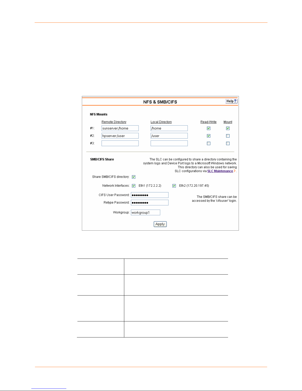
7: Services
The config directory, which contains saved configurations and is read-write.
The share allows users to access the contents of the directory or map the directory onto
a Windows computer. Users can also access the device port local buffers from the CIFS
share (see Device Ports – Logging on page 74).
To configure NFS and SMB/CIFS:
1. From the main menu, select Service - NFS & SMB/CIFS. The following page
displays:
2. Enter the following for up to three directories:
NFS Mounts
Remote Directory
Local Directory
Read-Write
Mount
3. Enter the following:
SecureLinx SLC User Guide 58
The remote NFS share directory in the format:
nfs_server_hostname or ipaddr:/exported/path
The local directory on the SLC on which to mount
the remote directory. The SLC creates the local
directory automatically.
If enabled, indicates that the SLC can write files
to the remote directory. If you plan to log port data
or save configurations to this directory, you must
enable this option.
Select the checkbox to enable the SLC to mount
the file to the NFS server. Disabled by default.
Page 59

SMB/CIFS Shares
7: Services
Share SMB/CIFS
directory
Network Interfaces
CIFS User
Password
and
Retype Password
Workgroup
Select the checkbox to enable the SLC to export
an SMB/CIFS share called “public.” Disabled by
default.
Select the network ports from which the share can
be seen. The default is for the share to be visible
on both network ports.
Only one user special username (cifsuser) can
access the CIFS share. Enter the CIFS user
password in both password fields. The default
user password is CIFSPASS.
More than one user can access the share with the
cifsuser user name and password at the same
time.
The Windows workgroup to which the SLC
belongs. Every PC exporting a CIFS share must
belong to a workgroup. Can have up to 15
characters.
4. To save, click Apply.
NFS and SMB/CIFS Commands
The following CLI commands correspond to the web page entries described above.
To mount a remote NFS share:
set nfs mount <one or more parameters>
Parameters:
locdir <Directory>
mount <enable|disable>
remdir <Remote NFS Directory>
rw <enable|disable>
Enables read/write access to remote directory.
Note: The remdir and locdir parameters are required, but if you specified them previously, you do
not need to provide them again.
To unmount a remote NFS share:
set nfs unmount <1|2|3>
To view NFS share settings:
show nfs
SecureLinx SLC User Guide 59
Page 60

7: Services
To configure the SMB/CIFS share, which contains the system and device port logs:
set cifs <one or more parameters>
Parameters:
eth1 <enable|disable>
eth2 <enable|disable>
state <enable|disable>
workgroup <Windows workgroup>
Note: The admin config command saves SLC configurations on the SMB/CIFS share.
To change the password for the SMB/CIFS share login (default is cifsuser):
set cifs password
To view SMB/CIFS settings:
show cifs
SecureLinx SLC User Guide 60
Page 61

88:: DDeevviiccee PPoorrttss
This chapter describes how to configure and use an SLC device port connected to an
external device, such as a server or a modem. The next chapter, 9: Connections,
describes how to use the Connections web page to connect external devices and
outbound network connections (such as Telnet or SSH) in various configurations. The
Console Port page allows you to configure the console port, if desired.
Connection Methods
A user can connect to a device port in one of the following ways:
1. Telnet or SSH to the Eth1 or Eth2 IP address, or connect to the console port, and
log in to the command line interface. At the command line interface, issue the
connect direct or connect listen commands.
2. If Telnet is enabled for a device port, Telnet to <Eth1 IP address>:<telnet port
number> or <Eth2 IP address>:<telnet port number>, where telnet port number is
uniquely assigned for each device port.
3. If SSH is enabled for a device port, SSH to <Eth1 IP address>:<ssh port number>
or <Eth2 IP address>:<ssh port number>, where ssh port number is uniquely
assigned for each device port.
4. If TCP is enabled for a device port, establish a raw TCP connection to <Eth1 IP
address>:<tcp port number> or <Eth2 IP address>:<tcp port number>, where tcp
port number is uniquely assigned for each device port.
5. If a device port has an IP address assigned to it, you can Telnet, SSH, or establish
a raw TCP connection to the IP address. For Telnet and SSH, use the default TCP
port number (23 and 22, respectively) to connect to the device port. For raw TCP,
use the TCP port number defined for TCP In to the device port on the Device Ports
– Settings page.
6. Connect a terminal or a terminal emulation program directly to the device port. If
logins are enabled, the user is prompted for a username and password and logs in
to the command line interface.
For #2, #3, #4, #5, and #6, if logins or authentication are not enabled, the user is directly
connected to the device port with no authentication.
For #1 and #6, if logins are enabled, the user is authenticated first, and then logged into
the command line interface. The user login determines permissions for acce ssing device
ports.
SecureLinx SLC User Guide 61
Page 62

Permissions
There are three types of permissions:
Direct (or data) mode: The user can interact with and monitor the device port
(connect direct command).
Listen mode: The user can only monitor the device port (connect listen
command).
Clear mode: The user can clear the contents of the device port buffer (set
locallog <port> clear buffer command).
The administrator and users with local user rights may assign individual port permissi ons
to local users. The administrator and users with remote authentication rights assign port
access to users authenticated by NIS, RADIUS, LDAP, Kerberos and TACACS+.
Global Port Settings
On the Device Ports page, you can set up the numbering of Telnet and SSH ports, view a
summary of current port modes, establish the maximum number of direct connections for
each device port, and select individual ports to configure.
8: Device Ports
1. From the main menu, select Device Ports. The following page displays:
SecureLinx SLC User Guide 62
Page 63

8: Device Ports
Current port numbering schemes for Telnet, SSH, and TCP ports display on the left.
The list of ports 1-16 on the right includes the individual ports and their current mode.
Note: To view additional ports, click the 17-32 button or the 33-48 button, as
appropriate.
Icons that represent some of the possible modes include:
Idle
The port is not in use.
The port is in data/text mode.
Note: You may set up ports to allow Telnet access using the IP
Settings on the Device Ports – Settings page.
An external modem is connected to the port. The user may dial into
or out of the port.
Telnet in or SSH in is enabled for the device port. The device port is
either waiting for a Telnet or SSH login or has received a Telnet or
SSH login (a user has logged in).
To set up Telnet and SSH port numbering:
1. Enter the following:
Telnet/SSH/TCP In Port Numbers
Starting Telnet
Port
Starting SSH Port
Each port is assigned a number for connecting via Telnet.
Enter a number (1025-65535) that represents the first port.
The default is 2000 plus the port number. For example, if
you enter 2001, subsequent ports are automatically
assigned numbers 2002, 2003, and so on.
Each port is assigned a number for connecting via SSH.
Enter a number (1025-65535) that represents the first port.
The default is 3000 plus the port number. For example, if
you enter 3001, subsequent ports are automatically
assigned numbers 3002, 3003, and so on.
Starting TCP Port
Caution: Ports 1-1024 are RFC-assigned and may conflict with services
running on the SLC. Avoid this range.
2. Click Apply to save the settings.
SecureLinx SLC User Guide 63
Each port is assigned a number for connecting through a
raw TCP connection. Enter a number (1025-65535) that
represents the first port. The default is 4000 plus the port
number. For example, if you enter 4001, subsequent ports
are automatically numbered 4002, 4003, and so on.
You can use a raw TCP connection in situations where a
TCP/IP connection is to communicate with a serial device.
For example, you can connect a serial printer to a device
port and use a raw TCP connection to spool print jobs to
the printer over the network.
Note: When using raw TCP connections to transmit binary
data, or where the break command (escape sequence) is
not required, set the Break Sequence of the respective
device port to null (clear it).
Page 64

8: Device Ports
To set limits on direct connections:
1. Enter the maximum number (1-10) of simultaneous direct connections for each
device port. The default is 1.
2. Click Apply to save the settings.
To configure a specific port:
1. You have two options:
Select the port from the ports list and click the Configure button. The Device
Ports – Settings page for the port displays.
Click the port number on the green bar at the top of each page.
2. Continue with Device Ports – Settings on page 64.
Global Commands
The following CLI commands correspond to the web page entries described above.
To configure settings for all or a group of device ports:
set deviceport global <one or more parameters>
Parameters:
maxdirect <1-10>
Sets the maximum number of direct connections for each device port.
sshport <TCP Port>
tcpport <TCP Port>
telnetport <TCP Port>
Port is a port number between 1025 and 65535.
To view global settings for device ports:
show deviceport global
Device Ports – Settings
On the Device Ports - Settings page, configure IP and data (serial) settings for individual
ports, and if the port connects to an external modem, modem settings as well.
To open the Device Ports – Settings page:
You have two options:
In the Device Ports page (described in the previous section), select the port from
the ports list and click the Configure button.
Click the desired port number in the green bar (shown below) at the top of any
page:
SecureLinx SLC User Guide 64
Page 65

The following page displays:
8: Device Ports
To enter device port settings:
1. Enter the following:
IP Settings
Mode
Name
Banner
SecureLinx SLC User Guide 65
The status of the port; displays automatically.
The name of the port. Valid characters are letters, numbers,
dashes (-), periods, and underscores ( _ ).
Text to display when a user connects to a device port by
means of Telnet, SSH, or TCP. If authentication is enabled
for the device port, the banner displays once the user
successfully logs in. Blank is the default.
Page 66

8: Device Ports
Break Sequence
Logging Click the Settings link to configure file logging, email logging,
Zero Port Counters
Connected to
Enable Telnet In
Enable SSH In
A series of one to ten characters users can enter on the
command line interface to send a break signal to the external
device. A suggested value is Esc+B (escape key, then
uppercase “B” performed quickly but not simultaneously).
You would specify this value as \x1bB, which is hexadecimal
(\x) character 27 (1B) followed by a B.
local logging, and PC Card logging. (See Device Ports –
Logging on page 74.)
Resets all of the numerical values in the Port Counters table
at the bottom of the page to zero (0).
The type of device connected to the device port. Presently,
the SLC supports Lantronix’s SecureLinx Remote Power
Manager (SLP8 and SLP16). If the type of device is not
listed, select undefined.
If you select SLP8 or SLP16, click Commands. The Device
Ports – SLP web page displays.
Enables access to this port through Telnet. Disabled by
default.
Enables access to this port through SSH. Disabled by
default.
Enable TCP in
Port
Authenticate
IP Address
Enables access to this port through a raw TCP connection.
Disabled by default.
Note: When using raw TCP connections to transmit binary
data, or where the break command (escape sequence) is not
required, set the Break Sequence of the respective device
port to null (clear it).
Automatically assigned Telnet, SSH, and TCP port numbers.
(See 8: Device Ports for information on setting up the
numbering scheme.) You may override this value, if desired.
If selected, the SLC requires user authentication before
granting access to the port. Authenticate is selected by
default for Telnet in and SSH in, but not for TCP in.
IP address used for this device port so a user can Telnet,
SSH, or establish a raw TCP connection to this address and
connect directly to the device port.
For Telnet and SSH, the default TCP port numbers (22 and
23, respectively) are used to connect to the device port. For
raw TCP, the TCP port number defined for TCP In to the
device port is used.
SecureLinx SLC User Guide 66
Page 67

8: Device Ports
Data Settings
Note: Check the serial device’s equipment settings and documentation for the
proper settings. The device port and the attached serial devi ce must have the
same settings.
Baud
Data Bits
Stop Bits
Parity
Flow Control
Enable Logins
The speed with which the device port exchanges data with
the attached serial device.
From the drop-down list, select the baud rate. Most devices
use 9600 for the administration port, so the device port
defaults to this value. Check the equipment settings and
documentation for the proper baud rate.
Number of data bits used to transmit a character. From the
drop-down list, select the number of data bits. The default
is 8 data bits.
The number of stop bit(s) used to indicate that a byte of
data has been transmitted. From the drop-down list, select
the number of stop bits. The default is 1.
Parity checking is a rudimentary method of detecting
simple, single-bit errors. From the drop-down list, select the
parity. The default is none.
A method of preventing buffer overflow and loss of data.
The available methods include none, xon/xoff (software),
and RTS/CTS (hardware). The default is none.
For serial devices connected to the device port, displays a
login prompt and authenticates users. Successfully
authenticated users are logged into the command line
interface.
Disabled is the default and is the correct setting if the
device port is the endpoint for a connection.
Hardware Signal Triggers
Check DSR on
Connect
Disconnect on
DSR
If this setting is enabled, the device port only establishes a
connection if DSR (Data Set Ready) is in an asserted state.
DSR should already be in an asserted state, not
transitioning to, when a connection attempt is made.
Disabled by default unless dial-in, dial-out, or dial-back is
enabled for the device port.
If a connection to a device port is currently in session, and
the DSR signal transitions to a de-asserted state, the
connection disconnects immediately. Disabled is the
default unless dial-in, dial-out, or dial-back is enabled for
the device port.
Modem Settings
Note: Depending on the State and Mode you select, different fields are
available.
State
SecureLinx SLC User Guide 67
Indicates whether an external modem is attached to the
device port. If enabling, set the modem to dial-out, dial-in,
dial-back, or dial-on-demand. Disabled by default.
Page 68

8: Device Ports
Mode
Initialization Script
Caller ID Logging
Modem Command Modem AT command used to initiate caller ID logging by
The format in which the data flows back and forth:
Text: In this mode, the SLC assumes that the modem will
be used for remotely logging into the command line. Text
mode can only be used for dialing in or dialing back. Text
is the default.
PPP: This mode establishes an IP-based link over the
modem. PPP connections can be used in dial-out mode
(e.g., the SLC connects to an external network), dial-in
mode (e.g., the external computer connects to the network
that the SLC is part of), or dial-on-demand.
Commands sent to configure the modem may have up to
100 characters. Consult your modem’s documentation for
recommended initialization options. If you do not specify
an initialization script, the SLC uses a default initialization
string of AT S7=45 SO=0 L1 V1 X4 &D2 &c1 E1 Q0.
Note: We recommend that the modem initialization script
always be preceded with AT and include E1 V1 x4 Q0 so
that the SLC may properly control the modem.
Select to enable the SLC to log caller IDs on incoming
calls. Disabled by default.
Note: For the Caller ID AT command, refer to the modem
user guide.
the modem.
Note: For the AT command, refer to the modem user
guide.
Modem Settings: Text Mode
Timeout
Logins
Dial Back
Number
If you selected Text mode, you can enable logins to time
out after the connection is inactive for a specified number
of minutes. The default is No. This setting is only
applicable for text mode connections. PPP mode
connections stay connected until either side drops the
connection. Disabled by default.
Users with dial-back access can dial into the SLC and
enter their login and password. (See Setting up Local
Users on page 94.) Once the SLC authenticates them, the
modem hangs up and dials them back.
Select the phone number the modem dials back on a fixed
number or a number associated with their login. If you
select Fixed Number, enter the number (in the format
2123456789).
Modem Settings: PPP Mode
Negotiate IP
Address
If the SLC and/or the serial device have dynamic IP
addresses (e.g., IP addresses assigned by a DHCP
server), select Yes. Yes is the default.
If the SLC or the modem have fixed IP addresses, select
No, and enter the local IP (IP address of the port) and
remote IP (IP address of the modem).
SecureLinx SLC User Guide 68
Page 69

8: Device Ports
Authentication Enables PAP or CHAP authentication for modem logins.
PAP is the default. With PAP, users are authenticated by
means of the Local Users and any of the remote
authentication methods that are enabled. With CHAP, the
CHAP Handshake fields authenticate the user.
CHAP Handshake
Enable NAT
Idle Timeout
Restart Delay
Dial-out
Number
Dial-out
Login
The host/secret (for UNIX systems) or user/password (for
Windows systems) used for CHAP authentication. May
have up to 128 characters.
Select to enable Network Address Translation (NAT) for
dial-in and dial-out PPP connections on a per modem
(device port or PC Card) basis. Users dialing into the SLC
access the network connected to Eth1 and/or Eth2.
Note: IP forwarding must be enabled on the
Network - Settings page for NAT to work. See 6: Basic
Parameters.
Timeout for PPP dial-in and dial-on-demand connections.
Select Yes (default) for the SLC to terminate the
connection if no traffic is received during the configured
idle time. Enter a value of from 1 to 9999 seconds. The
default is 30 seconds.
The number of seconds after the timeout and before the
SLC attempts another connection. The default is 30
seconds.
Phone number for dialing out to a remote system or serial
device. May have up to 20 characters. Any format is
acceptable.
User ID for dialing out to a remote system. May have up to
32 characters.
Password
Password for dialing out to a remote system. May have up
to 64 characters.
2. To save settings for just this port, click Apply.
3. To save selected settings to ports other than the one you are configuring:
a) From the Apply Settings drop-down box, select none, a group of settings, or
All.
b) In to Device Ports, type the device port numbers, separated by commas;
indicate a range of port numbers with a hyphen (e.g., 2, 5, 7-10).
Note: It may take a few minutes for the system to apply the settings to multiple
ports.
Port Counters
Port Counters describe the status of signals and interfaces. SLC updates and increments
the port counters as signals change and data flows in and out of the system. These
counters help troubleshoot connections or diagnose problems because they give the user
an overview of the state of various parameters. By setting them to zero and then rechecking them later, the user can view changes in status.
SecureLinx SLC User Guide 69
Page 70

8: Device Ports
The bottom part of the page displays the flow control lines and port statistics for the
device port. The system automatically updates these values. To reset them to zeros,
select the Zero port counters checkbox in the IP Settings section of the page.
Note: Status and statistics shown on the web interface represent a snapshot in tim e. To
see the most recent data, you must reload the web page.
Device Port Commands
The following CLI commands correspond to the web page entries described above.
To configure a single port or a group of ports:
Example: set deviceport port 2-5,6,12,15-16 baud 2400
set deviceport port <Device Port List or Name> <one or more device
port parameters>
Parameters:
auth <pap|chap>
banner <Banner Text>
baud <300-115200>
breakseq <1-10 Chars>
calleridcmd <Modem Command String>
calleridlogging <enable|disable>
chaphost <CHAP Host or User Name>
chapsecret <CHAP Secret or User Password>
The user defines the secret.
checkdsr <enable|disable>
closedsr <enable|disable>
databits <7|8>
device <none|slp8|slp16>
dialoutnumber <Phone Number>
dialoutlogin <User Login>
dialoutpassword <Password>
dialbacknumber <usernumber|Phone Number>
flowcontrol <none|xon/xoff|rts/cts>
idletimeout <disable|1-9999 seconds>
ipaddr <IP Address>
initscript <Initialization Script>
SecureLinx SLC User Guide 70
Page 71

8: Device Ports
A script that initializes a modem.
localipaddr <negotiate|IP Address>
logins <enable|disable>
modemmode <text|ppp>
modemstate
<disable|dialout|dialin|dialback|dialondemand>
name <Device Port Name>
nat <enable|disable>
parity <none|odd|even>
remoteipaddr <negotiate|IP Address>
restartdelay <PPP Restart Delay>
sshauth <enable|disable>
sshin <enable|disable>
sshport <TCP Port>
stopbits <1|2>
tcpauth <enable|disable>
tcpin <enable|disable>
tcpport <TCP Port>
telnetauth <enable|disable>
telnetin <enable|disable>
telnetport <TCP Port>
timeoutlogins <disable or 1-30>
To view the settings for one or more device ports:
show deviceport port <Device Port List or Name>
To view a list of all device port names:
show deviceport names
To view the modes and states of one or more device port(s):
You can optionally email the displayed information.
show portstatus [deviceport <Device Port List or Name>] [email
<Email Address>]
To view device port statistics and errors for one or more ports:
You can optionally email the displayed information.
show portcounters [deviceport <Device Port List or Name>] [email
<Email Address>]
To zero the port counters for one or more device ports:
show portcounters zerocounters <Device Port List or Name>
SecureLinx SLC User Guide 71
Page 72

Device Ports – SLP
In the Device Ports – SLP page, configure commands to send to an SLP connected to
the device port.
To open the Device Ports – SLP page:
1. In the IP Settings section of the Device Ports – Settings page, select SLP8 or
SLP16 in the Connected to field.
2. Click the Commands link. The following page displays:
8: Device Ports
To enter SLP commands:
1. Enter the following:
SLP Login
Password/Retype
Password
User ID for logging into the SLP.
Password for logging into the SLP.
SLP Status/Info
Outlet Status
Environmental
Status
System Info
Select All Outlets or Single Outlet to view all the status of
all outlets or a single outlet of the SLP. If you select Single
Outlet, enter a value of 1-8 for the SLP8 or 1-16 for the
SLP16.
Click the Outlet Status link to see the status of the selected
outlet(s).
Click the link to view the environmental status (e.g.,
temperature and humidity) of the SLP.
Click the link to see system information pertaining to the
SLP.
SLP Commands
Restart SLP
SecureLinx SLC User Guide 72
To restart the SLP, select the checkbox.
Page 73

8: Device Ports
Control Outlet
2. Click Apply.
Number of the outlet to be controlled (of 1-8 for the SLP8 or
1-16 for the SLP16) and select the command for the outlet
(No Action, Power On, Power Off, Cycle Power). No
Action is the default.
Device Port - SLP Commands
The following CLI commands correspond to the web page entries described above.
To send commands to (or control) a device connected to an SLC device port over
the serial port:
Note: Currently the only type of device supported for this type of interaction is the SLP.
set command <Device Port # or Name or List> <one or more
parameters>
Parameters:
slp auth login <User Login>
Establishes the authentication information to log into the SLP attached
to the device port.
slp restart
Issues the CLI command the SLP uses to restart itself.
slp outletcontrol state <on|off|cyclepower> [outlet
<Outlet #>]
Outlet # is 1-8 for SLP8 and 1-16 for SLP16.
The outletcontrol parameters control individual outlets.
slp outletstate [outlet <Outlet #>]
The outletstate parameter shows the state of all outlets or a single
outlet.
slp envmon
Displays the environmental status (e.g., temperature and humidity) of
the SLP.
slp system
Provides system information for the SLP.
Interacting with a Device Port
Once a device port has been configured and connected to an external device such as the
console port of an external server, the data received over the device port can be
monitored at the command line interface with the connect listen command, as
follows:
To connect to a device port to monitor it:
connect listen deviceport <Port # or Name>
In addition, you can send data out the device port (for example, commands issued to an
external server) with the connect direct command, as follows:
SecureLinx SLC User Guide 73
Page 74

8: Device Ports
To connect to a device port to monitor and/or interact with it, or to establish an
outbound network connection:
connect direct <endpoint>
endpoint is one of:
deviceport <Port # or Name>
ssh <IP Address> [port <TCP Port>][<SSH flags>]
where:
<SSH flags> is one or more of:
user <Login Name>
version <1|2>
command <Command to Execute>
tcp <IP Address> port <TCP Port>
telnet <IP Address> [port <TCP Port>]
udp <IP Address> port <UDP Port>
Notes:
To escape from the connect direct command when the endpoint of the
command is deviceport, tcp, or udp and return to the command line
interface, type the escape sequence assigned to the currently logged in user
(see Setting up Local Users on page 94 ). If the endpoint is telnet or SSH,
logging out returns the user to the command line prompt.
To escape from the connect listen command, press any key.
Setting up a user with an escape sequence is optional. For any NIS, LDAP,
RADIUS, Kerberos, or TACACS+ user, or any local user who does not have an
escape sequence defined, the default escape sequence is Esc+A.
Device Ports – Logging
The SLC products support port buffering of the data on the system's device ports as well
as notification of receiving data on a device port. Port logging is disabled by default. You
can enable more than one type of logging (local, NFS file, email/SNMP, or PC Card) at a
time. The buffer containing device port data is cleared when any type of logging is
enabled.
Local Logging
If local logging is enabled, each device port stores 256 Kbytes (approximately 400
screens) of I/O data in a true FIFO buffer. You may view this data (in ASCII format) at the
CLI with the show locallog command, through the CIFS share by viewing the text file
containing the contents of the FIFO buffer, or on the Device Ports – Logging web page.
The file containing the buffer is named <Device Port Number>_<Device Port Name>.log.
(For more information about the CIFS share, see NFS and SMB/CIFS on page 57.) You
clear the port buffer with the set locallog clear command.
Buffered data is normally stored in RAM and is lost in the event of a power failure if it is
not logged using an NFS mount solution. If the buffer data overflows the buffer capacity,
SecureLinx SLC User Guide 74
Page 75

8: Device Ports
only the oldest data is lost, and only in the amount of overrun (not in large blocks of
memory).
NFS File Logging
Data can be logged to a file on a remote NFS server. Data logged locally to the SLC is
limited to 256 Kbytes and may be lost in the event of a power loss. Data logged to a file
on an NFS server does not have these limitations. The system administrator can define
the directory for saving logged data on a port-by-port basis and configure file size and
number of files per port.
The directory path must be the local directory for one of the NFS mounts. For each
logging file, once the file size reaches the maximum, a new file opens for logging. Once
the number of files reaches the maximum, the oldest file is overwritten. The file naming
convention is: <Device Port Number>_<Device Port Name>_<File number>.log.
Examples: 02_Port-2_1.log
02_Port-2_2.log
02_Port-2_3.log
02_Port-2_4.log
02_Port-2_5.log
PC Card Logging
Data can be logged to a PC Card Compact Flash that is loaded into one of the PC Card
slots on the front of the SLC and properly mounted (see 11: PC Card). Data logged
locally to the SLC is limited to 256 Kbytes and may be lost in the event of a power loss.
Data logged to a PC Card Compact Flash does not have these limitations. The system
administrator can define the file size and number of files per port. For each logging file,
once the file size reaches the maximum, a new file opens for logging. Once the number
of files reaches the maximum, the oldest file is overwritten. The file naming convention is:
<Device Port Number>_<Device Port Name>_<File number>.log.
Examples: 02_Port-2_1.log
02_Port-2_2.log
02_Port-2_3.log
02_Port-2_4.log
02_Port-2_5.log
Email/SNMP Notification
The system administrator can configure the SLC to send an email alert message
indicating a particular condition detected in the device port log to the appropriate parties
or an SNMP trap to the designated NMS (see 7: Services). The email or trap is triggered
when a user-defined number of characters in the log from your server or device is
exceeded, or a specific sequence of characters is received.
Use the Device Ports – Logging page to set logging parameters on individual ports.
To set logging parameters:
1. In the IP Settings section of the Device Ports – Settings page, click the Settings
link in the Logging field. The following page displays:
SecureLinx SLC User Guide 75
Page 76

8: Device Ports
2. Enter the following:
Local Logging
Local Logging
Clear Local Log
View Local Log
Email/SNMP Traps
Email/Traps
Send
If you enable local logging, each device port stores 256
Kbytes (approximately 400 screens) of I/O data in a true
FIFO buffer. Disabled by default.
Select the checkbox to clear the local log.
Click this link to see the local log in text format.
Select the checkbox to enable email and SNMP logging.
Email logging sends an email message to pre-defined
email addresses or an SNMP trap to the designated NMS
(see 7: Services) when alert criteria are met. Disabled by
default.
If you enabled email and SNMP logging, select what type
of notification log to send: Email, SNMP, or Both. Email is
the default.
SecureLinx SLC User Guide 76
Page 77

8: Device Ports
Trigger on
Byte Threshold
Email Delay
Select the method of triggering a notification:
Byte Count: A specific number of bytes of data. This is the
default.
Text String Recognition: A specific pattern of characters,
which you can define by a regular expression.
Note: Text string recognition may negatively impact the
SLC’s performance, particularly when regular expressions
are used.
The number of bytes of data the port receives before the
SLC captures log data and sends a notification regarding
this port. The default is 100 bytes.
In most cases, the console port of your device does not
send any data unless there is an alarm condition. After the
SLC receives a small number of bytes, it perceives that
your device needs some attention. The SLC notifies your
technician when that point has been passed, and the
notification includes the logged data.
For example, a threshold preset at 30 characters means
that as soon as the SLC receives 30 bytes of data, it
captures log data and sends an email regarding this port.
A time limit of how long (in seconds), after the SLC detects
the trigger, that the device port captures data before
closing the log file (with a fixed internal buffer maximum
capacity of 1500 bytes) and sending a notification. The
default is 60 seconds.
Restart Delay
Text String
Email to
The number of seconds for the period after the notification
has been sent during which the device port ignores
additional characters received. The data is simply ignored
and does not trigger additional alarms until this time
elapses. The default is 60 seconds.
The specific pattern of characters the SLC must
recognize before sending a notification to the
technician about this port. The maximum is 100
characters. You may use a regular expression to
define the pattern. For example, the regular
expression “abc[def]g” recognizes the strings abcdg,
abceg, abcfg.
The SLC supports GNU regular expressions; for more
information, see:
http://www.codeforge.com/help/GNURegularExpr.html
http://www.delorie.com/gnu/docs/regex/regex.html
The complete email address of the message recipient(s)
for each device port(s). Each device port has its own
recipient list. To enter more than one email address,
separate the addresses with a single space. You can
enter up to 128 characters.
SecureLinx SLC User Guide 77
Page 78

8: Device Ports
Email Subject
NFS File Logging
NFS File Logging
Directory to Log to
Max Number of
Files
A subject text appropriate for your site. May have up
to 128 characters.
The email subject line is pre-defined for each port with its
port number. You can use the email subject to inform the
desired recipients of the problem on a certain server or
location (e.g., server location or other classification of your
equipment). This is helpful if the email message goes to
the system administrator’s or service technician's mobile or
wireless device (e.g., text messaging by means of email).
Note: The character sequence %d anywhere in the email
subject is replaced with the device port number
automatically.
Select the checkbox to log all data sent to the device port
to one or more files on an external NFS server. Disabled
by default.
The path of the directory where the log files will be stored.
Note: This directory must be a directory exported from an
NFS server mounted on the SLC. Specify the local
directory path for the NFS mount.
The maximum number of files to create to contain log data
to the port. These files keep a history of the data received
from the port. Once this limit is exceeded, the oldest file is
overwritten. The default is 10.
Max Size of Files
The maximum allowable file size in bytes. The default is
2048 bytes. Once the maximum size of a file is reached,
the SLC begins generating a new file.
PC Card Logging
PC Card Logging
Log To If port logging is to a PC Card, select the slot (Upper or
Max Number of
Files
Max Size of Files
3. To save, click Apply.
Select to enable PC Card logging. A PC Card Compact
Flash must be loaded into one of the PC Card slots on the
front of the SLC and properly mounted (see 11: PC Card ).
Disabled by default.
Lower) in which the PC Card has been inserted. Upper is
the default.
The maximum number of files to create to contain log data
to the port. These files keep a history of the data received
from the port. Once this limit is exceeded, the oldest file is
overwritten. The default is 10.
The maximum allowable file size in bytes. The default is
2048 bytes. Once the maximum size of a file is reached,
the SLC begins generating a new file. The default is 2048
bytes.
SecureLinx SLC User Guide 78
Page 79

8: Device Ports
Logging Commands
The following CLI commands correspond to the web page entries described above.
To configure logging settings for one or more device ports:
Example: set deviceport port 2-5,6,12,15-16 baud 2400 locallogging
enable
Note: Local logging must be enabled for a device port for the locallog commands to be
executed. To use the set locallog clear command, the user must have permission to clear
port buffers (see 10: User Authentication).
set deviceport port <Device Port List or Name> <one or more
deviceport parameters>
Parameters:
emaildelay <Email Delay>
emaillogging <disable|bytecnt|charstr>
emailrestart <Restart Delay>
emailsend <email|trap|both>
emailstring <Regex String>
emailsubj <Email Subject>
emailthreshold <Byte Threshold>
emailto <Email Address>
filedir <Logging Directory>
filelogging <enable|disable>
filemaxfiles <Max # of Files>
filemaxsize <Max Size of Files>
locallogging <enable|disable>
name <Device Port Name>
nfsdir <Logging Directory>
nfslogging <enable|disable>
nfsmaxfiles <Max # of Files>
nfsmaxsize <Size in Bytes>
pccardlogging <enable|disable>
pccardmaxfiles <Max # of Files>
pccardmaxsize <Size in Bytes>
pccardslot <upper|lower>
To view a specific number of bytes of data for a device port:
show locallog <Device Port # or Name> [bytes <Bytes To Display>]
1K is the default.
SecureLinx SLC User Guide 79
Page 80

To clear the local log for a device port:
set locallog clear <Device Port # or Name>
Note: The locallog commands can only be executed for a device port if local logging is enabled
for the port. The set locallog clear command can only be executed if the user has
permission to clear port buffers (see 10: User Authentication).
Console Port
The console port initially has the same defaults as the device ports. Use the Console Port
page to change the settings, if desired.
To set console port parameters:
1. From the main menu, select Device Ports - Console Port. The following page
displays:
8: Device Ports
2. Change the following as desired:
Baud
Data Bits
Stop Bits
Parity
The speed with which the device port exchanges data with
the attached serial device.
From the drop-down list, select the baud rate. Most devices
use 9600 for the administration port, so the console port
defaults to this value.
Number of data bits used to transmit a character. From the
drop-down list, select the number of data bits. The default
is 8 data bits.
The number of stop bits that indicate that a byte of data has
been transmitted. From the drop-down list, select the
number of stop bits. The default is 1.
Parity checking is a rudimentary method of detecting
simple, single-bit errors. From the drop-down list, select the
parity. The default is none.
SecureLinx SLC User Guide 80
Page 81

8: Device Ports
Flow Control
Timeout
A method of preventing buffer overflow and loss of data.
The available methods include none, xon/xoff (software),
and RTS/CTS (hardware). The default is none.
The number of minutes (1-30) after which an idle session
on the console is automatically logged out. Disabled by
default.
3. Click Apply to save the changes.
Console Port Commands
The following CLI commands correspond to the web page entries described above.
To configure console port settings:
set consoleport <one or more parameters>
Parameters:
baud <300-115200>
databits <7|8>
stopbits <1|2>
parity <none|odd|even>
flowcontrol <none|xon/xoff|rts/cts>
timeout <disable|1-30>
To view console port settings:
show consoleport
SecureLinx SLC User Guide 81
Page 82

99:: CCoonnnneeccttiioonnss
Chapter 8: Device Ports described ho w to configure and interact with an SLC device port
connected to an external device. This chapter describes how to use the Connections web
page to connect external devices and outbound network connections (such as Telnet or
SSH) in various configurations.
An SLC device port attached to an external device can be connected to one of the
following endpoints:
Another device port attached to an external device
Another device port with a modem attached
An outgoing Telnet or SSH session
An outgoing TCP or UDP network connection
This enables the user to set up connections such as those described in the next section.
You can establish a connection at various times:
Immediately. These connections are always re-established after reboot.
At a specified date and time. These connections connect if the date and time
have already passed.
After a specified amount of data or a specified sequence of data passes through
the connection. Following reboot, the connection is not reestablished until the
specified data passes through the connection.
SecureLinx SLC User Guide 82
Page 83

)
y
r
Typical Setup Scenarios for the SLC
Following are typical configurations in which SLC connections can be used, with
references to settings on the Connections and Device Ports web pages.
Terminal Server
In this setup, the SLC acts as a multiplexer of serial data to a single server computer.
Terminal devices are connected to the serial ports of the SLC and configured as a
Device Port to Telnet out type connection on the Connections page. The users of the
terminals can access the server as if they were connected directly to it by local serial
ports or a console.
VT100 Terminals
SLC Console Manager
9: Connections
Server
Serial
Connections
Telnet
Telnet
Sessions
(via Network
connection
Remote Access Server
In this setup, the SLC is connected to one or more modems by its device ports. Configure
the device ports on the Device Ports - Settings web page by selecting the Dial-in option
in the Modem Settings section. Most customers use the modems in PPP mode to
establish an IP connection to the SLC and either Telnet or SSH into the SLC. They could
also select text mode where, using a terminal emulation program, a user could dial into
the SLC and connect to the command line interface.
Phone
stem
S
Modems
Serial
SLC Console Manage
Internal
Network
Network
Connections
SecureLinx SLC User Guide 83
Page 84

9: Connections
r
Reverse Terminal Server
In this scenario, the SLC has one or more device ports connected to one or more serial
ports of a mainframe server. Users can access a terminal session by establishing a
Telnet or SSH session to the SLC. To configure the SLC, select the Enable Telnet In or
Enable SSH In option on the Device Ports – Settings web page.
PC
UNIX Server
SLC Console Manage
PC
Serial
Sessions
Telnet/SSH
Sessions
PC
Multiport Device Server
A PC can use the device ports on the SLC as virtual serial ports, enabling the ports to act
as if they are local ports to the PC. To use the SLC in this setup, the PC requires special
software, for example, Com Port Redirector (available on www.lantronix.com) or similar
software).
Serial
Printer
Modem
SLC Console Manager
Serial Connections
Raw TCP
Sessions
Windows/Linux PC
Serial
Device
SecureLinx SLC User Guide 84
Page 85

9: Connections
Console Server
For this situation, the SLC is configured so that the user can manage a number of servers
or pieces of network equipment using their console ports. The device ports on the SLC
are connected to the console ports of the equipment that the user would like to manage.
To manage a specific piece of equipment, the user can Telnet or SSH to a specific port or
IP address on the SLC and be connected directly to the console port of the end serve r or
device. To configure this setup, set the Enable Telnet In or Enable SSH In option on the
Device Ports – Settings web page for the device port in question. The user can
implement an extra remote management capability by adding a modem to one of the
device ports and setting the Dial-in option in the Modem Settings section of the Device
Ports – Settings web page. A user could then dial into the SLC using another modem and
terminal emulation program at a remote location.
Switch
Router
Web Server
Serial Terminal
Sessions
SLC Console Manager
Modem
Telnet/SSH
Sessions
PC
PC
PC
SecureLinx SLC User Guide 85
Page 86

Connection Configuration
To create a connection:
1. From the main menu, select Connections. The following page displays:
9: Connections
2. For a device port, enter the following:
Port
Data Flow
SecureLinx SLC User Guide 86
The number of the device port you are connecting.
This device port must be connected to an external
serial device and must not have command line
interface logins enabled, be connected to a
modem, or be running a loopback test.
Note: To see the current settings for this device
port, click the Settings link.
Select the arrow showing the direction
(bidirectional or unidirectional) the data will flow in
relationship to the device port you are connecting.
Page 87

9: Connections
to
Hostname
Port If the to field is set to Device Port or Modem on
SSH Out Options
From the drop-down list, select a destination for
the connection: a device port connected to a serial
device, a device port connected to a modem, or an
outbound network connection (Telnet, SSH, TCP
Port, or UDP Port).
Note: To see the current settings for a selected
device port, click the Settings link.
The host name or IP Address of the destination.
This entry is required if the to field is set to Telnet
out, SSH out, TCP port, or UDP port.
Device Port, enter the number of the device port.
For all other options, this is the TCP/UDP port
number, which is optional for Telnet out and SSH
out, but required for TCP Port and UDP Port.
Note: If you select Device Port, it must not have
command line interface logins enabled or be
running a loopback test.
Select one of the following optional flags to use for
the SSH connection.
User: Login ID to use for authenticating on the
remote host.
Version: Version of SSH. Select 1 or 2.
Command: Enter a specific command on the
remote host (for example, reboot).
Trigger
3. To save, click Apply.
Select the condition that will trigger a connection.
Options include:
Connect now: Connects immediately, or if you
reboot the SLC, immediately on reboot.
Connect at date/time: Connects at a specified
date and time. Use the drop-down lists to complete
the date and time. Upon rebooting, the SLC
reestablishes the connection if the date/time has
passed.
Auto-connect on characters transferring: Select
the arrow indicating the direction of the data
transfer and either the minimum number of
characters or a specific character sequence that
will trigger the connection.
You can select the direction of the data transfer
only if Data Flow is bidirectional. Upon rebooting,
the SLC does not reestablish the connection until
the specified data has passed through one of the
endpoints of the connection.
SecureLinx SLC User Guide 87
Page 88

9: Connections
To view, update, or disconnect a current connection:
The bottom of the Connections web page displays current connections.
1. To view details about a connection, hold the mouse over the arrow in the Flow
column.
2. To disconnect (delete) a connection, select the connection in the Select column
and click the Terminate button.
3. To reestablish the connection, create the connection again in the top part of the
page.
Connection Commands
These commands for configuring connections correspond to the web page entri es
described above.
To connect to a device port to monitor and/or interact with it, or to establish an
outbound network connection:
connect direct <endpoint>
Endpoint is one of:
deviceport <Port # or Name>
ssh <IP Address or Name> [port <TCP Port>] [<SSH
flags>]
where <SSH flags> is one or more of:
user <Login Name>
version <1|2>
command <Command to Execute>
tcp <IP Address> [port <TCP Port>]
telnet <IP Address or Name> [port <TCP Port>]
udp <IP Address> [port <UDP Port>]
To monitor a device port:
connect listen deviceport <Device Port # or Name>
SecureLinx SLC User Guide 88
Page 89

9: Connections
To connect a device port to another device port or an outbound network
connection (data flows in both directions):
connect bidirection <Port # or Name> <endpoint>
Endpoint is one of:
charcount <# of Chars>
charseq <Char Sequence>
charxfer <toendpoint|fromendpoint>
deviceport <Device Port # or Name>
date <MMDDYYhhmm[ss]>
exclusive <enable|disable>
ssh <IP Address or Name> [port <TCP Port] [<SSH
flags>]
where <SSH flags> is one or more of:
user <Login Name>
version <1|2>
command <Command to Execute>
tcp <IP Address> [port <TCP Port>]
telnet <IP Address or Name> [port <TCP Port>]
trigger <now|datetime|chars>
udp <IP Address> [port <UDP Port>]
Note: If the trigger is datetime (establish connection at a specified date/time), enter the date
parameter. If the trigger is chars (establish connection on receipt of a specified number or
characters or a character sequence), enter the charxfer parameter and either the charcount or
the charseq parameter.
To connect a device port to another device port or an outbound network
connection (data flows in one direction):
connect unidirection <Device Port # or Name> dataflow
<toendpoint⎢fromendpoint> <endpoint>
Endpoint is one of:
charcount <# of Chars>
charseq <Char Sequence>
datetime <MMDDYYhhmm[ss]>
deviceport <Port # or Name>
exclusive <enable|disable>
ssh <IP Address or Name> [port <TCP Port] >]
<SSH flags>]
where <SSH flags> is one or more of:
user <Login Name>
version <1|2>
SecureLinx SLC User Guide 89
Page 90

9: Connections
command <Command to Execute>
tcp <IP Address> [port <TCP Port>]
telnet <IP Address or Name> [port <TCP Port]
trigger <now|datetime|chars>
udp <IP Address> [port <UDP Port>]
Note: If the trigger is datetime (establish connection at a specified date/time), enter the date
parameter. If the trigger is chars (establish connection on receipt of a specified number or
characters or a character sequence), enter either the charcount or the charseq parameter.
To terminate a bidirectional or unidirectional connection:
connect terminate <Connection ID>
To view connections and their IDs:
Note: The connection IDs are in the left column of the resulting table. The connection ID associated
with a particular connection may change if the connection times out and is restarted.
show connections [email <Email Address>].
You can optionally email the displayed information.
To display details for a single connection:
You can optionally email the displayed information.
show connections connid <Connection ID> [email <Email Address>].
SecureLinx SLC User Guide 90
Page 91

1100:: UUsseerr AAuutthheennttiiccaattiioonn
Users who attempt to log in to the SLC by means of Telnet, SSH, the console port, or one
of the device ports are granted access by one or more authentication methods.
The User Authentication page provides a submenu of methods (Local Users, NIS, LDAP,
RADIUS, Kerberos, and TACACS+) for authenticating users attempting to log in. Use this
page to assign the order in which the SLC will use the methods. By default, local user
authentication is enabled and is the first method the SLC uses to authenticate users. If
desired, you can disable local user authentication or assign it a lower precedence.
Note: Regardless of whether local user authentication is enabled, the local user
sysadmin account is always available for login.
Authentication can occur using all methods, in the order of precedence, until a successful
authentication is obtained, or using only the first authentication method that responds (in
the event that a server is down).
If you have the same user name defined in multiple authentication methods, the result is
unknown.
Example:
There is an LDAP user "joe" and an NIS user "joe" and the order of
authentication methods is:
1 - Local Users
2 - LDAP
3 - NIS
User "joe" tries to log in. Because there is an LDAP user "joe," the SLC tries to
authenticate him against his LDAP password first. If he fails to log in, then the
SLC may (or may not) try to authenticate him against his NIS "joe" user
password.
To enable, disable, and set the precedence of authentication methods:
1. From the main menu, select User Authentication. The following page displays:
SecureLinx SLC User Guide 91
Page 92

10: User Authentication
2. To enable a method currently in the Disabled methods list, select the method and
press the left arrow to the left of the list. The methods include:
NIS (Network
Information
System)
LDAP (Lightweight
Directory Access
Protocol)
RADIUS (Remote
Authentication
Dial-In User
Service)
A network naming and administration system developed by
Sun Microsystems for smaller networks. Each host client or
server computer in the system has knowledge about the
entire system. A user at any host can access files or
applications on any host in the network with a single user
identification and password.
NIS uses the client/server model and the Remote Procedure
Call (RPC) interface for communication between hosts. NIS
consists of a server, a library of client programs, and some
administrative tools. NIS is often used with the Network File
System (NFS).
A set of protocols for accessing information directories,
specifically X.500-based directory services. LDAP runs over
TCP/IP or other connection-oriented transfer services.
An authentication and accounting system used by many
Internet Service Providers (ISPs). A client/server protocol, it
enables remote access servers to authenticate dial-in users
and authorize their access to the requested system or
service.
RADIUS allows a company to maintain user profiles in a
central database that all remote servers can share. It
increases security, allowing a company to set up a policy
that can be applied at a single administered network point.
Kerberos Kerberos is a network authentication protocol that enables
SecureLinx SLC User Guide 92
two parties to exchange private information across an
unprotected network.
It works by assigning a unique electronic credential, called a
ticket, to each user who logs on to the network. The ticket is
embedded in messages to identify the sender.
Page 93

10: User Authentication
TACACS+
(Terminal Access
Controller Access
Control System)
TACACS+ allows a remote access server to communicate
with an authentication server to determine whether the user
has access to the network. TACACS+ is a completely new
protocol and is not compatible with TACACS or XTACACS.
The SLC supports TACACS+ only.
3. To disable a method currently in the Enabled methods list, select the method and
click the right arrow between the lists.
4. To set the order in which the SLC will authenticate users, use the up and down
arrows to the left of the Enabled methods list.
5. For Attempt next method on authentication rejection, you have the following
options:
To enable the SLC to use all methods, in order of precedence, until it obtains a
successful authentication, select the check box. This is the default.
To enable the SLC to use only the first authentication method that responds (in
case a server is down or unavailable), clear the check box.
6. Click Apply.
Now that you have enabled one or more authentication methods, you must configure
them.
Authentication Commands
The following command for the command line interface corresponds to the web page
entries described above.
To set ordering of authentication methods:
Note: Local Users authentication is always the first method used. Any methods omitted from the
command will be disabled.
set auth <one or more parameters>
Parameters:
authusenextmethod <enable|disable>
kerberos <1-6>
ldap <1-6>
localusers <1-6>
nis <1-6>
radius <1-6>
tacacs <1-6>
To view authentication methods and their order of precedence:
show auth
SecureLinx SLC User Guide 93
Page 94

Setting up Local Users
You can configure the SLC to use local accounts to authenticate users who attempt to log
in via SSH, Telnet, the Web, or the console port.
To add an authenticated user:
1. From the main menu, select User Authentication - Local Users. The following
page displays.
10: User Authentication
2. Enter the following:
Enable Local
Users
Complex
Passwords
SecureLinx SLC User Guide 94
Select to enable all local users except sysadmin. The
sysadmin is always available regardless of how you set the
check box.
Select to enable the SLC to enforce rules concerning the
password structure (e.g., alphanumeric requirements,
number of characters, punctuation marks). Disabled by
default.
Complexity rules:
Passwords must be at least eight characters long.
They must contain one upper case letter (A-Z), one lower case
letter (a-z), one digit ( 0-9), and one punctuation character
(()`~!@#$%%^&*-+=\{}[]:;"'<>,.?/_).
Page 95

10: User Authentication
Login
UID
Password/
Retype Password
Enable for
Dial-back
Dial-back
Number
The name the user enters to log in to the SLC. May have up to
32 alphanumeric characters.
A unique numeric identifier the system administrator assigns to
each user. Valid UIDs are 101-4294967295.
Note: The UID must be unique. If it is not, SLC automatically
increments it. Starting at 101, the SLC finds the next unused
UID.
When a user logs into the SLC, the SLC prompts for a
password (up to 64 characters). The sysadmin establishes that
password here.
Select to grant a local user dial-back access (see
Device Ports – Settings on page 64). Users with dial-back
access can dial into the SLC and enter their login and
password. Once the SLC authenticates them, the modem
hangs up and dials them back. Disabled by default.
The phone number the modem dials back on depends on this
setting for the device port. The user is either dialed back on a
fixed number (specified on the Device Port - Settings page), or
on a number that is associated with the user’s login (specified
here).
3. Enter information about the specific functions the user will be permitted to access:
Listen Ports
Data Ports
Clear Port
Buffers
Escape
Sequence
The device ports that the user may access to view data using
the connect listen command. Enter the port numbers or
the range of port numbers (for example, 1, 5, 8, 10-15).
The device ports with which the user may interact using the
connect direct command. Enter the port numbers or the
range of port numbers.
The device port buffers the users may clear using the set
locallog clear command. Enter the port numbers or the
range of port numbers.
A series of one to ten characters that cause the SLC to leave
direct (interactive) mode. (To leave listen mode, press any key.)
A suggested value is Esc+A (escape key, then uppercase "A"
performed quickly but not simultaneously). You would specify
this value as \x1bA, which is hexadecimal (\x) character 27
(1B) followed by an A.
This setting allows the user to terminate the connect direct
command on the command line interface when the endpoint of
the command is deviceport, tcp, or udp.
For more information on escape sequences, see Interacting
with a Device Port on page 73.
SecureLinx SLC User Guide 95
Page 96

10: User Authentication
Shortcut
Break
Sequence
Custom Menu
A series of one to ten characters users can enter on the
command line interface to send a break signal to the external
device. A suggested value is Esc+B (escape key, then
uppercase “B” performed quickly but not simultaneously). You
would specify this value as \x1bB, which is hexadecimal (\x)
character 27 (1B) followed by a B.
If custom menus have been created (see Custom User Menus
on page 125), you can assign a default custom menu to the
user.
Note: In the Local Users table, if the menu assigned to a local
user no longer exists, it is marked with an asterisk (*).
4. Click the Add/Edit User button. The new user displays in the Local Users list
below.
5. Click Apply.
Notes:
To assign configuration rights for a local user, go to Setting up Local Users on
page 94.
The logged-in user's name displays above the menu. The menu displays only the
options for which the user has rights.
To add a user based on an existing user:
1. In the Local Users list, select the user. The fields in the top part of the page display
the current values for the user.
2. Change the Login to that of the new user. It is best to change the Password too.
3. Click the Add/Edit User button. A new user is created with the original user’s
settings.
4. Click Apply.
To edit a local user:
1. In the Local Users list, select the user. The fields in the top part of the page display
the current values for the user.
2. Update values as desired.
3. Click the Add/Edit User button. The updated values display in the Local Users list.
4. Click Apply.
To delete a local user:
1. In the Local Users list, select the user.
2. Click the Delete User button.
3. Click Apply.
To change the sysadmin password:
1. In the Local Users list, select sysadmin (first row).
2. Enter the new password in the Password and Retype Password fields.
SecureLinx SLC User Guide 96
Page 97

10: User Authentication
Note: You can change Escape Sequence and Break Sequence, if desired. You
cannot delete the UID or change the UID, port permissions, or custom menu.
3. Click Apply.
Local Users Commands
The following CLI commands correspond to the web page entries described above.
To configure local accounts (including sysadmin) who log in to the SLC by means
of SSH, Telnet, the Web, or the console port:
set localusers add|edit <User Login> <parameters>
Parameters:
allowdialback <enable|disable>
breakseq <1-10 Chars>
clearports <Port List>
custommenu <Menu Name>
dataports <Port List>
dialbacknumber <Phone Number>
escapeseq <1-10 Chars>
group <default|power|admin|>
listenports <Port List>
permissions <Permission List>
uid <User Identifier>
To set whether a complex login password is required:
set localusers complexpasswords <enable|disable>
To enable or disable authentication of local users:
set localusers state <enable|disable>
To set a login password for the local user:
set localusers password <User Login>
To delete a local user:
set localusers delete <User Login>
To view settings for all users or a local user:
show localusers [user <User Login>]
SecureLinx SLC User Guide 97
Page 98

User Permissions
The SLC has three default user groups: Administrators, Power Users, and Default Users.
Each has a predefined set of rights: users inherit rights from the user group to which they
belong. These rights are in addition to the current functions that a user can perform at the
CLI:
The table below shows the mapping of groups and user rights.
You cannot deny a user rights defined for the group, but you can add or remove all other
rights at any time.
10: User Authentication
connect direct/listen
set locallog/password/history/cli
show datetime/deviceport/locallog/portstatus/portcounters/
history/cli/user
Table 10-1. User Group Rights
User Right Administrators Power Users Default Users
Full Administrative Rights
Networking
Services
Date/Time
Local Users
Remote Authentication
SSH Keys
User Menus
Device Ports
PC Card
Reboot/Shutdown
Firmware/Configuration
Diagnostics and Reports
SLC Network
Web Access
y
y y
y
y y
y
y
y
y
y
y
y y
y
y y
y
y
Note: You cannot change the rights associated with each group; a future release will
provide that functionality.
By default, the system assigns new users to the Default Users group, but you can change
their group membership at any time. If you change a user's rights while the user is logged
into the web or CLI, the results do not take effect until the next time the user logs in.
To assign user rights:
SecureLinx SLC User Guide 98
Page 99

10: User Authentication
1. On the User Authentication – Local Users page, select a user from the table and
click Settings to the right of the User Rights field. The User Authentication – Local
User Rights page displays for the selected user.
2. Enter the following:
Login (view only)
Group
User ID of selected user.
Select the group to which the user will belong:
Default Users: This group has only the most basic rights
(described above).
Power Users: This group has the same rights as Default
Users plus Networking, Date/Time, Reboot & Shutdown,
and Diagnostics & Reports.
Administrators: This group has all possible rights.
3. Select or clear the checkboxes for the following rights:
Full Administrative
Networking
Services
Date/Time
Right to perform any function on the SLC.
Right to enter network and routing settings.
Right to enable and disable system and audit logging, SSH
and Telnet logins, SNMP, and SMTP. Includes NFS and
CIFS.
Right to set the date and time.
Local Users
Remote
Authentication
SSH Keys
SecureLinx SLC User Guide 99
Right to add or delete local users on the system.
Right to assign a remote user to a user group and assign a
set of rights to the user. Includes configuring remote
authentication methods and ordering
Right to set SSH keys for authenticating users.
Page 100

10: User Authentication
User Menus
Device Ports
PC Card
Reboot &
Shutdown
Firmware &
Configuration
Diagnostics &
Reports
SLC Network
Web Access
Right to create or edit a custom user menu for the CLI.
Right to enter device port settings. Includes creating
bidirectional and unidirection connections
Right to enter modem settings for PC cards. Includes
managing storage PC Cards.
Right to shutdown or reboot the SLC.
Right to upgrade the firmware on the unit and save or restore
a configuration (all settings).
Right to obtain diagnostic information and reports about the
unit.
Right to view and manage SLCs on the local subnet.
Right to access Web-Manager.
4. Click Apply.
Note: The logged-in user's name displays above the menu. The menu displays only the
options for which the user has rights.
Local User Rights Commands
The following CLI commands correspond to the web page entries described above.
To add a local user to a user group or to change the group the user belongs to:
set localusers add|edit <user> group <default|power|admin>
To set a local user's permissions (not defined by the user group):
set localusers add|edit <user> permissions <Permission List>
where
<Permission List> is one or more of nt, sv, dt, lu, ra, sk, um, dp, pc,
rs, rc, dr, wb, sn, ad
To remove a permission, type a minus sign before the two-letter abbreviation for a user
right.
To view the rights of the currently logged-in user:
show user
Remote User Permissions
Remote users are those not in the database of local users. They are authenticated by
methods such as NIS, LDAP, and RADIUS.
The system administrator can assign remote users to a user group, assign a set of user
rights, and grant port permissions to individual remote users.
SecureLinx SLC User Guide 100
 Loading...