

Page 1

SCS Reference Manual
For the Lantronix Family of Secure Console Servers
Part Number 900-235
Revision D December 2003
Page 2

The information in this guide may change without notice. The manufacturer assumes no responsibility for
any errors which may appear in this guide.
Copyright 2003, Lantronix. All rights reserved. No part of the contents of this book may be transmitted or
reproduced in any form or by any means without the written permission of Lantronix. Printed in the United
States of America.
The revision date for this manual is December 2003.
Part Number: 900-235
Revision D
WARNING
This equipment has been tested and found to comply with the limits for a Class A digital device pursuant to
Part 15 of FCC Rules. These limits are designed to provide reasonable protection against such interference
when operating in a commercial environment. This equipment generates, uses, and can radiate radio
frequency energy, and if not installed and used in accordance with this guide, may cause harmful
interference to radio communications.
Operation of this equipment in a residential area is likely to cause interference in which case the user, at his
or her own expense, will be required to take whatever measures may be required to correct the interference.
Changes or modifications to this device not explicitly approved by Lantronix will void the user's authority
to operate this device.
Page 3

Contents
1: Introduction .............................................................................................................1-1
1.1 What Is New................................................................................................................1-1
1.2 How To Use This Manual............................................................................................1-1
2: Gettin g S tar t e d........................................................................................................ 2-1
2.1 Configuration Methods..... ................. ................ ................. ................. ................. ....... 2-1
2.1.1 EZWebCon................................................................................................................................2-1
2.1.2 Web Bro w ser In ter f ace............... .... ............... ............................................................................2-1
2.1.3 Command Line ..........................................................................................................................2-2
2.2 Rebooting........ ................. ................. ................ ................. ................. ................. ....... 2-5
2.2.1 Sending a Broadcast Message .................................................................................................2-5
2.2.2 Restoring Factory Defaults........................................................................................................2-5
2.2.3 Reloading Operational Software ...............................................................................................2-6
2.2.4 Editing Boot Parameters ...........................................................................................................2-6
2.3 System Passwords............................................................. ................. ................. ....... 2-7
2.3.1 Login Password.........................................................................................................................2-7
2.3.2 Privileged Password..................................................................................................................2-8
2.4 Basic Configuration........................... ................ ................. ................. ................. ....... 2-9
2.4.1 Changing the Server Name.......................................................................................................2-9
2.4.2 Changing the Local Prompt.......................................................................................................2-9
2.4.3 Changin g th e Logi n Prom p ts.. ... ......................................... ....................................................2-10
2.4.4 Setting the Date and Time.......................................................................................................2-10
2.4.5 802.11 Configuration...............................................................................................................2-11
2.5 Configuration Files............................................................. ................. ................. ..... 2-16
2.5.1 Creating a Configuration File...................................................................................................2-16
2.5.2 Using a Configuration File.......................................................................................................2-17
2.6 Disk Management.............................................................. ................. ................. ..... 2-18
2.6.1 Flash Disk................................................................................................................................2-18
2.6.2 ATA Cards...............................................................................................................................2-18
3: Console Se r v e r Fea t u r e s .... .. ................................................................................. 3-1
3.1 Overview of Console Servers......................................................................................3-1
3.2 Event Port Logging ..................................................................................................... 3-2
3.2.1 Enabling Port Logging...............................................................................................................3-2
3.2.2 Viewin g th e Po r t Log ... ... ................ ...........................................................................................3-2
3.3 Email Alerts for Serial Events......................................................................................3-3
3.4 Configuring Menu Mode..............................................................................................3-4
3.4.1 Menu Configuration at the Command Line................................................................................3-4
3.4.2 Menu Configuration Files ..........................................................................................................3-5
3.4.3 Nested Menus ...........................................................................................................................3-7
3.5 Login Banner Pages ............................................................................................ ....... 3-8
3.6 Managing the Attached Devices ....... ................ ................. ................. ................. ....... 3-8
3.6.1 In-Band Management................................................................................................................3-8
3.6.2 Out of Band Management .........................................................................................................3-9
3.6.3 Conne cti n g from th e Loca l > Pro m pt.. ... ... .............................................................................. ....3-9
3.6.4 Serial Break Handling................................................................................................................3-9
3.7 Serial Port Configurations .........................................................................................3-14
3.7.1 Enabling the Incoming Password............................................................................................3-14
3.7.2 Setting the Port Access Mode.................................................................................................3-14
3.7.3 Displaying Port Status .............................................................................................................3-14
i
Page 4

4: Basic Remote Networking ..................................................................................... 4-1
4.1 Remote Connection Types..........................................................................................4-1
4.1.1 Remote Dial-in ..........................................................................................................................4-1
4.1.2 LAN to LAN ...............................................................................................................................4-2
4.2 Managing Connections With Sites..............................................................................4-2
4.2.1 Creating a New Site ..................................................................................................................4-3
4.2.2 Displaying Existing Sites ...........................................................................................................4-4
4.2.3 Editing Sites ..............................................................................................................................4-4
4.2.4 Testing Sites..............................................................................................................................4-5
4.2.5 Deleting Sites............................................................................................................................4-5
4.2.6 Using Sites for Incoming Connections ......................................................................................4-5
4.2.7 Using Sites for Outgoing Connections ......................................................................................4-6
4.2.8 ISP Site Connections with NAT.................................................................................................4-6
4.3 IP Address Negotiation .... ................. ................ ................. ................. ................. ....... 4-7
4.4 IP Routing ....... ................. ................. ................ ................. ................. ................. .......4-8
4.4.1 Routes for Outgoing LAN to LAN .............................................................................................4-8
4.4.2 Routes for Incoming LAN to LAN ..............................................................................................4-9
4.4.3 Routes for Remote User Dial-ins...............................................................................................4-9
4.4.4 Configuring RIP for Sites.........................................................................................................4-10
4.5 Incoming Connections ....................................................... ................. ................. .....4-11
4.5.1 Star ting PPP /S li p for In com in g C onn ections.......................... .................................................4- 11
4.5.2 Incoming Connection Sequence ............................................................................................4-13
4.5.3 Configuring Incoming Connections .........................................................................................4-14
4.6 Outgoing Connections ....................................................... ................. ................. .....4-16
4.6.1 Ports for Outgoing Connections .............................................................................................. 4-17
4.6.2 Telephone Numbers................................................................................................................4-17
4.6.3 Authentication..........................................................................................................................4-17
4.6.4 Configuring Outgoing Connections .........................................................................................4-18
4.7 Monitoring Networking Activity..................................................................................4-20
4.8 Examples ....... ................. ................. ................ ................. ................. ................. .....4-21
4.8.1 LAN to LAN—Calling One Direction Only................................................................................4-21
4.8.2 LAN to LAN—Bidirectional (Symmetric) Callin g......................................................................4-22
4.8.3 Remot e Di al- i n User Exa mpl e .......................................................... ....................................... 4-24
5: Additional Remote Ne t w o rk ing ... .. .................................... ... ................................. 5-1
5.1 Basic Security .................................. ................ ................. ................. ................. ....... 5-1
5.1.1 Port Authentication....................................................................................................................5-1
5.1.2 Filter Lists ..................................................................................................................................5-2
5.2 Chat Scripts .... ................. ................. ................ ................. ................. ................. .......5-3
5.2.1 Creating a Chat Script...............................................................................................................5-3
5.2.2 Editing and Adding Entries........................................................................................................5-3
5.2.3 Configuring Timeouts ................................................................................................................5-4
5.2.4 Setting Markers .........................................................................................................................5-4
5.3 Bandwidth On Demand...............................................................................................5-4
5.3.1 How Bandwidth is Controlled ....................................................................................................5-5
5.3.2 Disadvantages of Additional Bandwidth....................................................................................5-5
5.3.3 Configuring Bandwidth Allocated to Sites .................................................................................5-6
5.3.4 Displaying Current Bandwidth Settings.....................................................................................5-8
5.3.5 Restoring Default Bandwidth Settings....................................................................................... 5-8
5.3.6 Monitoring Bandwidth Utilization...............................................................................................5-8
5.4 Increasing Performance... ................. ................ ................. ................. ................. ....... 5-8
5.4.1 Filtering Unwanted Data............................................................................................................5-8
5.4.2 Compr e ssi n g Dat a and C orr e cti ng Er ror s .. ............................ ...................................................5 -9
5.4.3 Adding Bandwidth .....................................................................................................................5-9
5.4.4 IP Header Compression ............................................................................................................5-9
5.5 Reducing Cost ................. ................. ................ ................. ................. ................. ..... 5-10
ii
Page 5

5.5.1 Inactivity Logouts.....................................................................................................................5-10
5.5.2 Restricting Packets with Startup Filters...................................................................................5-10
5.5.3 Reduci n g th e Numb e r of Ports U sed.... ... ............................ ....................................................5-10
5.5.4 Using Higher Speed Modems .................................................................................................5-10
5.5.5 Restricting Connections to Particular Times............................................................................5-11
5.5.6 Increasing Requirements for Adding Additional Bandwidth.....................................................5-12
5.5.7 Controlling Frequency of Calls................................................................................................5-12
5.6 Using the SCS Without Dialup Modems ................................................................... 5-13
5.6.1 Situations Where Dialup Modems Are Not Used.....................................................................5-13
5.6.2 Configuring the Unit for Modemless Connections ...................................................................5-14
5.7 Character Mode Sites ...............................................................................................5-15
5.8 Examples ........ ................. ................. ................ ................. ................. ................. ..... 5-16
5.8.1 Creating a Chat Script.............................................................................................................5-16
5.8.2 Creating a Simple Firewall ......................................................................................................5-16
5.8.3 Controlling Access During Weekend Hours............................................................................5-16
6: IP .... .................................................................................... ...................................... 6-1
6.1 IP Addresses... ................. ................. ................ ................. ................. ................. .......6-1
6.1.1 IP Addresses for Incoming Connections ...................................................................................6-2
6.1.2 IP Addresses For Outgoing Connections..................................................................................6-4
6.2 Subnet Masks . ................. ................. ................ ................. ................. ................. ....... 6-5
6.2.1 Length of Subnet Masks............................................................................................................6-6
6.3 Name Resolving............... ................. ................ ................. ................. ................. ....... 6-6
6.3.1 Configuring the Domain Name Service (DNS) ..........................................................................6-7
6.3.2 Specifying a Default Domain Name ..........................................................................................6-7
6.3.3 Adding Hosts to the Host Table.................................................................................................6-7
6.4 Header Compression........................................ ................. ................. ................. ....... 6-8
6.5 Establishing Sessions....................................... ................. ................. ................. ....... 6-8
6.5.1 Telnet and Rlogin Sessions.......................................................................................................6-9
6.5.2 SSH Sessions .........................................................................................................................6-10
6.5.3 Restricting Connections to SSH..............................................................................................6-17
6.5.4 Disabling HTTP and FTP ........................................................................................................6-17
6.6 IP Security....... ................. ................. ................ ................. ................. ................. .....6-17
6.6.1 Configuring the Security Table................................................................................................6-18
6.6.2 Cleari n g Tab le En tr ie s.............................................................................................................6-18
6.7 IP Routing ....... ................. ................. ................ ................. ................. ................. .....6-19
6.7.1 How Packets are Routed.........................................................................................................6-19
6.7.2 Routing Tables........................................................................................................................6-19
6.7.3 Using RIP ................................................................................................................................6-22
6.7.4 Proxy ARP...............................................................................................................................6-22
6.7.5 Using the NetBIOS Nameserver (NBNS)................................................................................6-22
6.7.6 Routing and Subnetworks.......................................................................................................6-23
6.8 Displaying the IP Configuration......................... ................. ................. ................. ..... 6-23
6.9 Examples ........ ................. ................. ................ ................. ................. ................. ..... 6-25
6.9.1 IP Address Assignment for Remote Networking .....................................................................6-25
6.9.2 General IP Setup ....................................................................................................................6-26
6.9.3 Addin g Sta tic Rou te s... .............................................................................. ..............................6-26
6.9.4 Default Routes to a Site ..........................................................................................................6-26
7: PPP. .. .................................................................. ...................................................... 7-1
7.1 LCP................................................................... ................. ................. ................. ....... 7-1
7.1.1 Packet Sizes..............................................................................................................................7-1
7.1.2 Header Compression ................................................................................................................7-1
7.1.3 Character Escaping...................................................................................................................7-1
7.1.4 PPP Authentication ...................................................................................................................7-2
7.1.5 CBCP ........................................................................................................................................7-3
iii
Page 6

7.2 NCP ................ ................. ................. ................ ................. ................. ................. ....... 7-3
7.3 Starting PPP ... ................. ................. ................ ................. ................. ................. .......7-3
7.3.1 User-Initiated PPP.....................................................................................................................7-4
7.3.2 Automatic Detection of PPP......................................................................................................7-4
7.3.3 Dedicated PPP ..........................................................................................................................7-4
7.4 Multilink PPP.................... ................. ................ ................. ................. ................. .......7-4
7.4.1 Configuring the Calling SCS......................................................................................................7-4
7.4.2 Configuring the Receiving SCS.................................................................................................7-6
7.5 Restoring Default PPP Settings..................................................................................7-7
7.6 Pocket PC PPP Support .............................................................................................7-7
7.7 Character Mode Sites .................................................................................................7-7
7.8 Troubleshooting ................................................ ................. ................. ................. ....... 7-8
8: Ports . .................................................................. ...................................................... 8-1
8.1 Using Port Commands................................................................................................8-1
8.2 Setting Port Access..................................................................................................... 8-1
8.3 Starting a Port.............................................................................................................8-1
8.3.1 Waiting for Character Input .......................................................................................................8-2
8.3.2 Starting Automatically................................................................................................................8-2
8.4 Port Modes...... ................. ................. ................ ................. ................. ................. .......8-3
8.4.1 Character Mode.........................................................................................................................8-3
8.4.2 PPP Mode .................................................................................................................................8-3
8.4.3 SLIP Mode.................................................................................................................................8-3
8.5 Automatic Protocol Detection...................................................................................... 8-4
8.6 Port-Specific Session Configuration............................................................................8-4
8.6.1 Multiple Sessions ......................................................................................................................8-4
8.6.2 Switching Between Sessions ....................................................................................................8-5
8.6.3 Exiting Sessions........................................................................................................................8-5
8.6.4 Monitoring Session Activity .......................................................................................................8-7
8.6.5 Setti n g Ses sio n C har act er is tic s......... ... .....................................................................................8-7
8.7 Preferred/Dedicated Protocols & Hosts ...................................................................... 8-8
8.7.1 Dedicated Protocols ..................................................................................................................8-8
8.7.2 Preferred/Dedicated Hosts ........................................................................................................8-9
8.7.3 Saving Autostart Characters .....................................................................................................8-9
8.8 Port Restrictions............... ................. ................ ................. ................. ................. ....... 8-9
8.8.1 Locking a Port ...........................................................................................................................8-9
8.8.2 Enabling Signal Check ............................................................................................................8-10
8.8.3 Username/Password Protection..............................................................................................8-10
8.8.4 Automatic Logouts...................................................................................................................8-11
8.8.5 Restricting Commands............................................................................................................8-12
8.8.6 Receipt of Broadcast Messages..............................................................................................8-12
8.8.7 Dialback...................................................................................................................................8-12
8.8.8 Enabling Menu Mode ..............................................................................................................8-12
8.9 Serial Port Configuration...........................................................................................8-13
8.9.1 Naming a Port .........................................................................................................................8-13
8.9.2 Specifying a Username ...........................................................................................................8-13
8.9.3 Notification of Character Loss .................................................................................................8-13
8.9.4 Padding Return Characters.....................................................................................................8-14
8.9.5 Setting the Device Type ..........................................................................................................8-14
8.9.6 Specifying a Terminal Type.....................................................................................................8-14
8.9.7 Transmitting Serial Data..........................................................................................................8-14
8.9.8 Restoring Default Port Settings...............................................................................................8-15
8.10 RS-485 Configuration ...................................................... ................. ................. .....8-15
8.10.1 Two-wire Mode......................................................................................................................8-16
8.10.2 Four-wire Mode .....................................................................................................................8-17
8.10.3 Termination ...........................................................................................................................8-18
iv
Page 7

8.10.4 RS-422 Networking ...............................................................................................................8-18
8.11 Flow Control................... ................. ................ ................. ................. ................. .....8-18
8.11.1 Hardware Flow Control..........................................................................................................8-18
8.11.2 Software Flow Control...........................................................................................................8-19
8.11.3 Setting Up Flow Control ........................................................................................................8-19
8.12 Serial Signals................................................................... ................. ................. ..... 8-20
8.12.1 DSR (Data Set Ready) ..........................................................................................................8-21
8.12.2 DCD (Data Carrier Detect)....................................................................................................8-21
8.12.3 DTR (Data Terminal Ready)..................................................................................................8-22
8.13 Virtual Ports .. ................. ................. ................ ................. ................. ................. .....8-22
8.14 Modem Emulation............................................................ ................. ................. ..... 8-23
9: Modems ....... ............................. ............................................................................... 9-1
9.1 Setup and Wiring ........................................................................................................ 9-1
9.2 Modem Speeds................................. ................ ................. ................. ................. ....... 9-2
9.2.1 Serial Speed..............................................................................................................................9-2
9.2.2 Line Speed ................................................................................................................................9-2
9.3 Modem Profiles.................................................................. ................. ................. ....... 9-2
9.3.1 Using a Profile...........................................................................................................................9-3
9.3.2 Editing a Profile .........................................................................................................................9-3
9.3.3 Profile Settings..........................................................................................................................9-5
9.3.4 Profiles for Modems with External Switches..............................................................................9-8
9.4 Modem and SCS Interaction....................................................................................... 9-8
9.4.1 Initialization................................................................................................................................9-8
9.4.2 Outgoing Calls...........................................................................................................................9-8
9.4.3 Incoming Calls...........................................................................................................................9-9
9.4.4 When a Port is Logged Out.......................................................................................................9-9
9.4.5 Compression .............................................................................................................................9-9
9.4.6 Error Correction.......................................................................................................................9-10
9.4.7 Modem Security ......................................................................................................................9-11
9.4.8 Autostart..................................................................................................................................9-11
9.4.9 Dialback...................................................................................................................................9-11
9.5 Terminal Adapters............ ................. ................ ................. ................. ................. ..... 9-12
9.6 Caller-ID........................... ................. ................ ................. ................. ................. .....9-12
9.7 Examples ........ ................. ................. ................ ................. ................. ................. ..... 9-13
9.7.1 Typical Modem Configuration..................................................................................................9-13
9.7.2 Modem Configuration Using Generic Profile...........................................................................9-13
9.7.3 Editing Modem Strings ............................................................................................................9-15
9.8 Troubleshooting ................................................ ................. ................. ................. ..... 9-16
10: Modem Sh a rin g............................................................................. ...................... 10-1
10.1 Services ........ ................. ................. ................ ................. ................. ................. .....10-1
10.1.1 Creatin g a Se rv ice........... ................ ......................................................................................10-1
10.1.2 Assoc iati n g Ports w it h a Ser vi ce ...........................................................................................10-1
10.1.3 Display in g Cur r ent Se r vi ces ..... ............................. ................................................................10-2
10.2 Sharing Modems............................. ................ ................. ................. ................. ..... 10-3
10.2.1 Configu rin g an IP Mod em Po o l Se rv ic e ... ......................................... ....................................1 0 -3
10.2.2 Using the COM Port Redirector............................................................................................. 10-3
10.2.3 Connec ti ng to a TC P Listener Service ........ ... ... ....................................................................10-3
10.2.4 Connec ti ng to a Se ria l Por t ......................................... ..........................................................10-4
10.2.5 Connec ti ng to a Se rv ic e or Po rt ... ... ..................................................... ................................. 10-4
10.3 Examples ........................................ ................ ................. ................. ................. .....10-4
10.3.1 Configuring the Redirector ....................................................................................................10-5
10.3.2 Configu rin g the PC C omm u nic a tio ns Soft w are . .... ................................................................1 0 -5
v
Page 8

11: Securit y...... .. .................................................................................... .................... 11 -1
11.1 Incoming Authentication . ................. ................ ................. ................. ................. .....11-1
11.1.1 Character Mode Logins.........................................................................................................11-1
11.1.2 PPP Logins............................................................................................................................11-3
11.1.3 SLIP Logins...........................................................................................................................11-4
11.2 Outgoing Authentication . ................. ................ ................. ................. ................. .....11-4
11.2.1 Outgoing Character Mode Connections ................................................................................11-5
11.2.2 Outgoing PPP Connections...................................................................................................11-5
11.2.3 Outgoing SLIP Connections..................................................................................................11-5
11.3 Dialback ........ ................. ................. ................ ................. ................. ................. .....11-5
11.3.1 The Dialback Process ...........................................................................................................11-6
11.3.2 Dialback from Character Mode.............................................................................................. 11-6
11.3.3 Dialback from SLIP/PPP Mode .............................................................................................11-7
11.3.4 Dialback Using CBCP ...........................................................................................................11-7
11.3.5 Potential Dialback Drawbacks...............................................................................................11-8
11.3.6 Port User Restrictions ...........................................................................................................11-8
11.4 Database Configuration .................................. ................. ................. ................. .....11-9
11.4.1 Local (NVR) Database ..........................................................................................................11-9
11.4.2 Kerberos..............................................................................................................................11-11
11.4.3 RADIUS...............................................................................................................................11-14
11.4.4 SecurID ...............................................................................................................................11-17
11.4.5 UNIX Password File ............................................................................................................11-19
11.5 User Restrictions............ ................. ................ ................. ................. ................. ... 11-19
11.5.1 Privileged Commands .........................................................................................................11-19
11.5.2 IP Address Restriction.........................................................................................................11-20
11.5.3 Controlling Use of Set PPP/SLIP Commands.....................................................................11-20
11.5.4 Securing a Port....................................................................................................................11-20
11.5.5 Locking a Port .....................................................................................................................11-21
11.5.6 Forcing Execution of Commands ........................................................................................11-21
11.5.7 Restri cti n g Multi p l e Auth en tic a te d Logi ns ............................ ...............................................11-21
11.6 Network Restrictions....................................... ................. ................. ................. ...11-22
11.6.1 Incoming Telnet/Rlogin Connections...................................................................................11-22
11.6.2 Outgoing Rlogin Connections..............................................................................................11-22
11.6.3 Limiting Port Access............................................................................................................11-22
11.6.4 Disabling the FTP and HTTP Servers .................................................................................11-23
11.6.5 Packet F ilt ers an d Fir ewa ll s .. ... .................................................................. .........................11-23
11.7 Event Logging.................................................................. ................. ................. ... 11-25
11.7.1 Setting the Destination ........................................................................................................11-25
11.7.2 Logging Levels ....................................................................................................................11-26
11.8 Examples ..... ................. ................. ................ ................. ................. ................. ...11-28
11.8.1 Database Search Order ......................................................................................................11-28
11.8.2 Terminal User Forced to Execute Command......................................................................11-28
11.8.3 Multiple-User Authentication ...............................................................................................11-29
11.8.4 Outgoing LAN to LAN Connection.......................................................................................11-30
11.8.5 Creatin g a Fire wa ll ................................................ ..................................................... .........11-30
11.8.6 Dialback...............................................................................................................................11-33
11.9 Troubleshooting .............................................. ................. ................. ................. ... 11-33
12: Comma n d Re f ere n c e.......................................................................................... 12- 1
12.1 Command Descriptions .. ................. ................ ................. ................. ................. .....12-1
12.2 About Strings ................. ................. ................ ................. ................. ................. ..... 12-2
12.3 Conventions Used in This Chapter .........................................................................12-2
12.4 Modem Commands........ ................. ................ ................. ................. ................. ..... 12-3
12.4.1 Define Ports Modem Answer.................................................................................................12-3
12.4.2 Define Ports Modem Attention ..............................................................................................12-4
12.4.3 Define Ports Modem Busy.....................................................................................................12-4
vi
Page 9

12.4.4 Define Ports Modem CallerID................................................................................................12-5
12.4.5 Define Ports Modem Carrierwait ...........................................................................................12-5
12.4.6 Define Ports Modem Commandprefix ...................................................................................12-6
12.4.7 Define Ports Modem Compression .......................................................................................12-6
12.4.8 Define Ports Modem Connected ...........................................................................................12-7
12.4.9 Define Ports Modem Control .................................................................................................12-8
12.4.10 Define Ports Modem Dial ....................................................................................................12-8
12.4.11 Define Ports Modem Error...................................................................................................12-9
12.4.12 Define Ports Modem Errorcorrection.................................................................................12-10
12.4.13 Define Ports Modem Getsetup..........................................................................................12-10
12.4.14 Define Ports Modem Init....................................................................................................12-11
12.4.15 Define Ports Modem Nocarrier..........................................................................................12-12
12.4.16 Define Ports Modem Nodialtone .......................................................................................12-12
12.4.17 Define Ports Modem OK ...................................................................................................12-13
12.4.18 Define Ports Modem Reset ...............................................................................................12-13
12.4.19 Define Ports Modem Ring .................................................................................................12-14
12.4.20 Define Ports Modem Save ................................................................................................12-14
12.4.21 Define Ports Modem Speaker ...........................................................................................12-15
12.4.22 Define Ports Modem Statistics ..........................................................................................12-15
12.4.23 Define Ports Modem Type.................................................................................................12-16
12.4.24 Show/Monitor/List Modem.................................................................................................12-16
12.5 IP/Network Commands................................... ................. ................. ................. ...12-18
12.5.1 Clear/Purge Hosts ...............................................................................................................12-18
12.5.2 Clear/Purge IP Factory........................................................................................................12-18
12.5.3 Clear/Purge IP NAT Table...................................................................................................12-18
12.5.4 Clear/Purge IP Route ..........................................................................................................12-19
12.5.5 Clear/Purge IP Security.......................................................................................................12-19
12.5.6 Clear/Purge IP Trusted........................................................................................................12-20
12.5.7 Connect...............................................................................................................................12-20
12.5.8 Disconnect...........................................................................................................................12-22
12.5.9 Purge IP Ethernet................................................................................................................12-22
12.5.10 Rlogin ................................................................................................................................12-22
12.5.11 Send..................................................................................................................................12-23
12.5.12 Set/Define 80211...............................................................................................................12-24
12.5.13 Set/Define Hosts ...............................................................................................................12-34
12.5.14 Set/Define IP All/Ethernet..................................................................................................12-35
12.5.15 Set/Define IP Create .........................................................................................................12-37
12.5.16 Set/Define IP Domain........................................................................................................12-38
12.5.17 Set/Define IP Ethernet.......................................................................................................12-38
12.5.18 Set/Define IP Host Limit ....................................................................................................12-38
12.5.19 Set/Define IP IPaddress ....................................................................................................12-39
12.5.20 Set/Define IP Loadhost .....................................................................................................12-39
12.5.21 Set/Define IP Nameserver.................................................................................................12-39
12.5.22 Set/Define IP NAT.............................................................................................................12-40
12.5.23 Set/Define IP NAT Table ...................................................................................................12-41
12.5.24 Set/Define IP NBNS ..........................................................................................................12-41
12.5.25 Set/Define IP Route...........................................................................................................12-42
12.5.26 Set/Define IP Routing........................................................................................................12-43
12.5.27 Set/Define IP Security .......................................................................................................12-43
12.5.28 Set/Define IP Subnet.........................................................................................................12-45
12.5.29 Set/Define IP TCP Keepalive ............................................................................................12-45
12.5.30 Set/Define IP Timeserver ..................................................................................................12-46
12.5.31 Set/Define IP Trusted ........................................................................................................12-47
12.5.32 Set/Define IP Trusted ........................................................................................................12-47
12.5.33 Show IP Counters .............................................................................................................12-48
12.5.34 Show/Monitor/List Hosts....................................................................................................12-48
12.5.35 Show/Monitor/List IP .........................................................................................................12-49
12.5.36 SSH...................................................................................................................................12-51
12.5.37 Telnet ................................................................................................................................12-51
vii
Page 10

12.6 Port Commands............................................................... ................. ................. ... 12-52
12.6.1 List Email.............................................................................................................................12-52
12.6.2 Lock.....................................................................................................................................12-52
12.6.3 Logout Port..........................................................................................................................12-53
12.6.4 Purge Port ...........................................................................................................................12-53
12.6.5 Purge Email.........................................................................................................................12-54
12.6.6 Resume...............................................................................................................................12-54
12.6.7 Set Noprivileged ..................................................................................................................12-54
12.6.8 Snoop Port ..........................................................................................................................12-55
12.6.9 Define Email .......................................................................................................................12-55
12.6.10 Set/De fi n e Por ts Ac ce ss....................................................................................................12-57
12.6.11 Set/De fi n e Por ts Au th en ti ca te ...........................................................................................12-58
12.6.12 Set/De fi n e Por ts Au to ba u d............... ... ..............................................................................12-58
12.6.13 Set/De fi n e Por ts Au to c o nnect .......... .................................................................................12-59
12.6.14 Set/De fi n e Por ts Au to s ta r t................ ... ... ...........................................................................12-60
12.6.15 Set/De fi n e Por ts Ba c kw a rd Sw itch............ ........................................................................12-61
12.6.16 Set/De fi n e Por ts Br e ak............... .......................................................................................12-62
12.6.17 Define Ports Backspace ....................................................................................................12-63
12.6.18 Set/De fi n e Por ts Br o ad ca st ...............................................................................................12-64
12.6.19 Set/De fi n e Por ts C ha racter Size ...... ... ... ... ........................................................................12-64
12.6.20 Set/De fi n e Por ts C omm a nd Com ple ti o n ... ..................................................... ...................12-65
12.6.21 Set/De fi n e Por ts D at ase n d............... ... ... ......................................... ..................................12-66
12.6.22 Define Ports Dedicated .....................................................................................................12-68
12.6.23 Define Ports Dialback........................................................................................................12-70
12.6.24 Set/De fi n e Por ts D SRL og o ut...... ... ........................................ ............................................12-70
12.6.25 Set/De fi n e Por ts D TR Wa it...... ...........................................................................................12-71
12.6.26 Define Ports Event Email Serialdata ................................................................................12-71
12.6.27 Set/De fi n e Por ts F low Con tr ol ....... ... .............................................................................. ...12-72
12.6.28 Set/De fi n e Por ts F orw a rd Sw itc h ........ ... ... ... .....................................................................12-73
12.6.29 Set/De fi n e Por ts In activity Logout ....... ................ ..............................................................12-74
12.6.30 Set/De fi n e Por ts Lo ca l Swi t ch ....... ... .................................................................................12-74
12.6.31 Set/De fi n e Por ts Lo ss Noti f ic at ion.......... ... ... ..................................................... ................12-75
12.6.32 Set/De fi n e Por ts Me n u ........... ...........................................................................................12-76
12.6.33 Set/De fi n e Por ts Mo d em Em u l at ion ..................................................................................12 - 76
12.6.34 Set/De fi n e Por ts N ame..... .................................................................. ...............................12-77
12.6.35 Set/De fi n e Por ts Pa r it y ........ ... ...........................................................................................12-77
12.6.36 Set/De fi n e Por ts Pa s sw o rd ........... ....................................................................................12-78
12.6.37 Set/De fi n e Por ts Po c ke tP C ................................. ..............................................................12-79
12.6.38 Set/De fi n e Por ts Pr e fer re d ......... ... ... .............................................................................. ...12-79
12.6.39 Define Ports PPP ..............................................................................................................12-81
12.6.40 Define Ports PPPdetect.....................................................................................................12-84
12.6.41 Set/De fi n e Por ts Pr i nt er.....................................................................................................12-84
12.6.42 Set/De fi n e Por ts Se c u rity .... ... .... .......................................................................................12-85
12.6.43 Set/De fi n e Por ts Se r ia l Log ............................................................................................ ...12-85
12.6.44 Set/De fi n e Por ts Se s si o n Limi t............... ... ........................................................................12-86
12.6.45 Set/De fi n e Por ts Si g na l Ch eck ...... ... .................................................................................12-86
12.6.46 Define Ports SLIP..............................................................................................................12-87
12.6.47 Set/De fi n e Por ts SL IPdetect.......... ... ............................ .....................................................12-88
12.6.48 Set/De fi n e Por ts Sp ee d.......... .... ........................................ ...............................................12-88
12.6.49 Set/De fi n e Por ts Sto p.......... ... ...........................................................................................12-89
12.6.50 Set/De fi n e Por ts T eln et Pad..............................................................................................12-89
12.6.51 Set/De fi n e Por ts T erm Ty p e........... ... ... ... ...........................................................................12-90
12.6.52 Set/De fi n e Por ts T ype ...................... .................................................................................12-90
12.6.53 Set/De fi n e Por ts U ser n ame. ... ............................................................................... ...........
12.6.54 Set/De fi n e Por ts Ve r if ic at ion .......................................................................................... ...12-92
12.6.55 Set Privileged/Noprivileged ...............................................................................................12-92
12.6.56 Define Protocols RS485 ....................................................................................................12-93
12.6.57 Set Session .......................................................................................................................12-94
12.6.58 Set PPP.............................................................................................................................12-95
.12-91
viii
Page 11

12.6.59 Set SLIP ............................................................................................................................12-96
12.6.60 Show/Monitor/List Ports ....................................................................................................12-96
12.6.61 Show RS485 .....................................................................................................................12-98
12.6.62 Show/Monitor Sessions.....................................................................................................12-98
12.6.63 Test Port............................................................................................................................12-99
12.6.64 Unlock Port......................................................................................................................12-100
12.7 Service Commands........ ................. ................ ................. ................. ................. . 12-101
12.7.1 Clear/Purge Service ..........................................................................................................12-101
12.7.2 Remove Queue .................................................................................................................12-101
12.7.3 Set/Define Service.............................................................................................................12-102
12.7.4 Set/Define Service Banner ................................................................................................12-103
12.7.5 Set/Define Service Binary ................................................................................................. 12-103
12.7.6 Set/Define Service EOJ.....................................................................................................12-103
12.7.7 Set/Define Service Formfeed ............................................................................................12-104
12.7.8 Set/Define Service Identification .......................................................................................12-104
12.7.9 Set/Define Service Password............................................................................................12-105
12.7.10 Set/Define Service Ports .................................................................................................12-105
12.7.11 Set/Define Service Postscript..........................................................................................12-106
12.7.12 Set/Define Service PSConvert ........................................................................................12-106
12.7.13 Set/Define Service RTEL ................................................................................................12-106
12.7.14 Set/Define Service SOJ...................................................................................................12-107
12.7.15 Set/Define Service TCPport ............................................................................................12-107
12.7.16 Set/Define Service Telnetport .........................................................................................12-108
12.7.17 Show/Monitor/List Services.............................................................................................12-108
12.8 Server Commands........................................................... ................. ................. . 12-111
12.8.1 Clear/Purge Menu .............................................................................................................12-111
12.8.2 Initialize Server..................................................................................................................12-111
12.8.3 Set/Define Menu................................................................................................................12-112
12.8.4 Set/Define Protocol FTP....................................................................................................12-114
12.8.5 Set/Define Protocol HTTP .................................................................................................12-114
12.8.6 Set/Define Protocol SSH Mode.........................................................................................12-114
12.8.7 Set/Define Server Altprompt .............................................................................................12-115
12.8.8 Set/Define Server BOOTP ................................................................................................12-115
12.8.9 Set/Define Server BOOTGATEWAY.................................................................................12-116
12.8.10 Set/De fi n e Ser ve r Br o adc a st............... ... .........................................................................12-116
12.8.11 Set/De fi n e Ser ve r Bu ffe r ing. ... .... .....................................................................................12-116
12.8.12 Set/De fi n e Ser ve r Clo ck ...... .............................................................................. ..............12-117
12.8.13 Set/Define Server DHCP.................................................................................................12-117
12.8.14 Set/De fi n e Ser ve r Host Limit...........................................................................................12-118
12.8.15 Set/De fi n e Ser ve r In act i vi ty .... .... ............... ......................................................................12-118
12.8.16 Set/De fi n e Ser ve r In com in g ............................................................................................12-119
12.8.17 Set/De fi n e Ser ve r Loa dh os t .......... ... ............................................................................... 1 2-120
12.8.18 Set/De fi n e Ser ve r Loc k .......... ......................................................................................... 12-120
12.8.19 Set/De fi n e Ser ve r Log in Pa ssw ord ........... ... ...................................................................12-121
12.8.20 Set/De fi n e Ser ve r Nam e ............... ..................................................................................12-121
12.8.21 Set/De fi n e Ser ve r Nam e se rv er ........ ... ... ... ......................................................................12-122
12.8.22 Set/De fi n e Ser ve r Pa ss wo r d Lim it.... ...............................................................................1 2- 122
12.8.23 Set/De fi n e Ser ve r Pr iv il ege d Pa ss wo rd ....... ... .... ............................................................12-123
12.8.24 Set/De fi n e Ser ve r Pr o mpt ............. ..................................................................................12-123
12.8.25 Set/De fi n e Ser ve r RAR P ..... ... .... .............................................................................. .......12-125
12.8.26 Set/De fi n e Ser ve r Ret ra n sm it Li mit ..... ... ... ......................................................................12-125
12.8.27 Set/De fi n e Ser ve r Rlo g in............... ... ................................................................. ..............12-125
12.8.28 Set/De fi n e Ser ve r Se ss io n Lim it......................................................................................12-126
12.8.29 Set/De fi n e Ser ve r Sil e ntb o ot ...........................................................................................12-126
12.8.30 Set/De fi n e Ser ve r So ftwa r e........... ... ...............................................................................12-126
12.8.31 Set/De fi n e Ser ve r St ar tu p fil e............... ... ... ......................................................................12-127
12.8.32 Set/De fi n e Ser ve r Ti mez o n e .................................................... .......................................1 2-128
12.8.33 Show/Monitor/List Menu..................................................................................................12-129
12.8.34 Show/Monitor/List Server ................................................................................................12-129
ix
Page 12

12.8.35 Show/Monitor/List Timezone...........................................................................................12-131
12.8.36 Show/Monitor Users........................................................................................................12-131
12.8.37 Source.............................................................................................................................12-131
12.9 Site Commands ............. ................. ................ ................. ................. ................. . 12-132
12.9.1 Define Site.........................................................................................................................12-132
12.9.2 Define Site Authentication .................................................................................................12-132
12.9.3 Define Site Bandwidth.......................................................................................................12-134
12.9.4 Define Site Chat ................................................................................................................12-136
12.9.5 Define Site Dial on Hangup ...............................................................................................12-138
12.9.6 Define Site Filter................................................................................................................12-138
12.9.7 Define Site Idle..................................................................................................................12-139
12.9.8 Define Site IP ....................................................................................................................12-140
12.9.9 Define Site MTU ................................................................................................................12-142
12.9.10 Define Site Permanent .................................................................................................... 12-143
12.9.11 Define Site Port ...............................................................................................................12-143
12.9.12 Define Site Protocol.........................................................................................................12-145
12.9.13 Define Site Telephone.....................................................................................................12-145
12.9.14 Define Site Time..............................................................................................................12-146
12.9.15 Logout Site ......................................................................................................................12-148
12.9.16 Purge Site........................................................................................................................12-148
12.9.17 Show/Monitor/List Sites...................................................................................................12-149
12.9.18 Test Site ..........................................................................................................................12-150
12.10 Security Commands ..... ................. ................ ................. ................. ................. .12-151
12.10.1 Clear/Purge Authentication .............................................................................................12-151
12.10.2 Clear/Purge Dialback ......................................................................................................12-152
12.10.3 Clear/Purge Filter ............................................................................................................12-152
12.10.4 Clear/Purge SNMP..........................................................................................................12-153
12.10.5 Set/Define Authentication................................................................................................ 12-153
12.10.6 Set/Define Authentication Kerberos ................................................................................12-154
12.10.7 Set/Define Authentication Local ......................................................................................12-156
12.10.8 Set/Define Authentication RADIUS .................................................................................12-157
12.10.9 Set/Define Authentication SecurID..................................................................................12-159
12.10.10 Set/Define Authentication Strictfail................................................................................12-161
12.10.11 Set/Define Authentication TFTP ....................................................................................12-162
12.10.12 Set/Define Authentication Unique .................................................................................12-163
12.10.13 Set/Define Authentication User .....................................................................................12-163
12.10.14 Set/Define Dialback.......................................................................................................12-165
12.10.15 Set/Define Filter.............................................................................................................12-166
12.10.16 Set/Define Filter Any .....................................................................................................12-167
12.10.17 Set/Define Filter Generic...............................................................................................12-168
12.10.18 Set/Define Filter IP ........................................................................................................12-169
12.10.19 Set/Define FTP..............................................................................................................12-172
12.10.20 Set/Define HTTP ...........................................................................................................12-172
12.10.21 Set/Define Logging........................................................................................................12-172
12.10.22 Set/Define Password..................................................................................................... 12-176
12.10.23 Set/Define Server Incoming Secure..............................................................................12-176
12.10.24 Set/Define SNMP ..........................................................................................................12-177
12.10.25 Show/Monitor/List Authentication..................................................................................12-177
12.10.26 Show/Monitor/List Dialback...........................................................................................12-178
12.10.27 Show/Monitor/List Filter.................................................................................................12-178
12.10.28 Show/Monitor/List Logging............................................................................................12-179
12.10.29 Show/Monitor/List SNMP ..............................................................................................12-179
12.10.30 PC Card Commands .....................................................................................................12-179
12.10.31 Show PCCard................................................................................................................12-179
12.11 Navigation/Help Commands ........ ................ ................. ................. ................. . 12-180
12.11.1 Apropos...........................................................................................................................12-180
12.11.2 Backwards.......................................................................................................................12-180
12.11.3 Broadcast ........................................................................................................................12-180
12.11.4 Cls ...................................................................................................................................12-181
x
Page 13

12.11.5 Disk ................................................................................................................................12-182
12.11.6 Finger ..............................................................................................................................12-186
12.11.7 Forwards .........................................................................................................................12-186
12.11.8 Help.................................................................................................................................12-187
12.11.9 Monitor ............................................................................................................................12-187
12.11.10 Netstat...........................................................................................................................12-187
12.11.11 Ping ...............................................................................................................................12-188
12.11.12 Resolve .........................................................................................................................12-188
12.11.13 Save ..............................................................................................................................12-189
12.11.14 Show/Monitor Queue.....................................................................................................12-190
12.11.15 Show Version ................................................................................................................12-191
12.11.16 Zero Counters ...............................................................................................................12-192
A: Enviro nme n t St r in gs........... ...................................... .............................................A- 1
A.1 Usage ............. ................. ................. ................ ................. ................. ................. .......A-1
A.1.1 Multiple Strings ............................................................................................A-1
A.2 Available Strings............................... ................ ................. ................. ................. .......A-1
A.2.1 Usage Examples..........................................................................................A-1
B: Show 802. 1 1 Errors................................................................................................B- 1
B.1 Introduction..... ................. ................. ................ ................. ................. ................. .......B-1
B.2 Error Bits.......................... ................. ................ ................. ................. ................. .......B-1
B.2.1 Leftmost Number .........................................................................................B-1
B.2.2 Rightmost Number.......................................................................................B-3
C: SNMP Supp o rt..... ............................................... ....................................................C-1
C.1 Support............................ ................. ................ ................. ................. ................. .......C-1
C.2 Security .......... ................. ................. ................ ................. ................. ................. .......C-1
D: Supported RADIUS Attributes .......................... ................ ......... ................ ......... ..D-1
D.1 Authentication Attributes ................................................... ................. ................. .......D-1
D.1.1 Access-Request...........................................................................................D-1
D.1.2 Access-Accept.............................................................................................D-2
D.2 Accounting Attributes ........................................................ ................. ................. .......D-4
D.3 Examples........ ................. ................. ................ ................. ................. ................. .......D-5
D.3.1 Configuring Authenticated PPP Connections..............................................D-5
D.3.2 Forcing a Telnet Connection to Preferred Host...........................................D-6
D.3.3 Forcing a Telnet Connection to a Specific Port ...........................................D-6
D.3.4 Preventing RADIUS Authentication .............................................................D-6
Index
xi
Page 14

xii
Page 15

1: Introduction
The Lantronix SCS family of Secure Console Servers provides secure communication for remote users to
access local network resources. Our Servers enable IT professionals to configure and administer servers,
routers, switches, telephone equipment, or any device with a serial port.
In addition to remote networking capabilities, the SCS includes traditional terminal server functionality
such as security features and modem control. The security features include dialback, passwords, database
authentication, and menu mode. The SCS also allows automatic modem configuration and control.
This reference manual provides instructions for advanced configuration as well as the complete command
set for all products in the SCS family. Many of these features can also be setup using EZWebCon and the
web browser interface, and are noted as such.
Before reading this manual, follow the installation procedure described in your Installation Guide. Basic
configuration for your SCS is also described in your Installation Guide.
1.1 What Is New
This manual now includes instructions for the SCS100 and SCS400, the newest members of the Lantronix
family of Secure Console Servers, in addition to instructions for the SCS200, SCS1600, and SCS3200.
1.2 How To Use This Manual
The rest of this reference manual is divided as follows:
Chapter 2, Getting Started, provides information on system passwords, rebooting, and basic time and
date setup.
Chapter 3, Console Server Features, discusses the console server features of the SCS.
Chapter 4, Basic Remote Networking, contains instructions on configuring LAN to LAN and remote
node networking.
Chapter 5, Additional Remote Networking, describes how to optimize your remote networking
connection and introduces basic security concepts.
Chapter 6, IP, configures the Internet Protocol (IP) for your SCS.
Chapter 7, PPP, contains conceptual information about the Point-to-Point Protocol (PPP).
Chapter 8, Ports, describes how to configure the SCS’s serial ports.
Chapter 9, Modems, explains how to configure modems that are attached to the serial ports or, for
certain SCS models, installed in the PC card slot.
Chapter 10, Modem Sharing, describes how to configure the attached modems if they are to be shared.
1-1
Page 16

Introduction How To Use This Manual
Chapter 11, Security, offers a comprehensive description of all security features.
Chapter 12, Command Reference, is divided into sections for Navigation/Help, IP/Network, Port,
Modem, Service, Server, Site, and Security commands.
Appendix A, Environment Strings, discusses the environment strings that can be used with several of
the commands described in Chapter 12.
Appendix B, Show 802.11 Errors, defines the error bits that appear in the Show 80211 screen.
Appendix C, covers the SNMP features supported by the SCS.
Appendix D, Sup ported RADIUS Attributes, lists and explains the RADIUS attributes currently
supported by the SCS.
1-2
Page 17
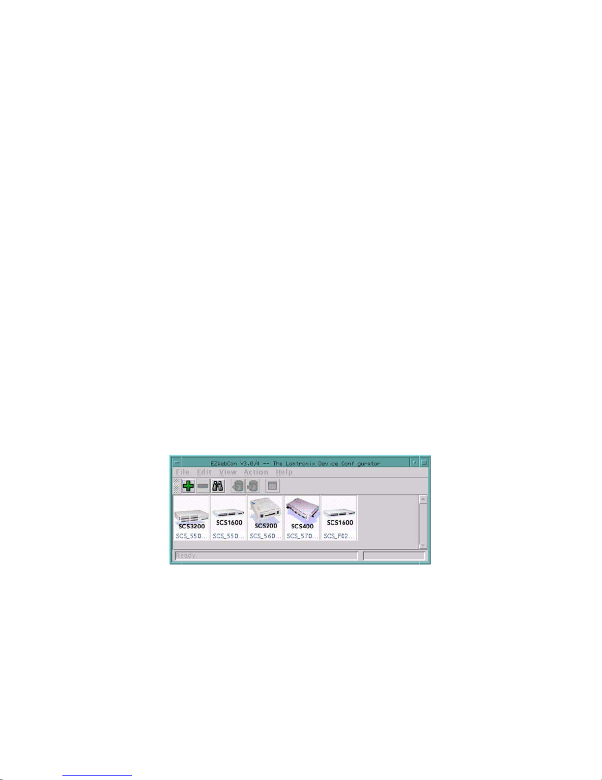
2: Getting Started
This chapter covers basic configuration that should get you started using the SCS. Topics include methods
for setting up the SCS and ongoing maintenance issues such as restoring factory default settings. You can
perform almost all of these configurations using EZWebCon (the recommended method for initial
configuration), the web browser interface (recommended for further configurations), or by issuing
commands at the command line (Local> prompt).
This chapter assumes that you have completed the following steps, which are described in your Installation
Guide:
The SCS is running operational code (i.e. the unit has successfully booted).
The SCS is connected to an Ethernet.
The SCS has been assigned an IP address.
2.1 Configuration Methods
EZWebCon is the recommended method for initial configuration. However, the web browser interface and
the command line offer options for advanced configuration.
2.1.1 EZWebCon
The EZWebCon utility is the easiest way to initially configure the unit. EZWebCon guides you through
configuration using a graphical interface.
Figure 2-1: The EZWebCon Utility
EZWebCon is included on the CD-ROM that is shipped with each SCS unit. Instructions are listed in the
Read Me file, also located on the CD-ROM. For assistance once EZWebCon is running, refer to the
EZWebCon online help.
2.1.2 Web Browser Interface
The web browser interface allows you to log into and configure your SCS using a standard web browser.
To connect to your SCS using the web browser interface, do one of the following:
2-1
Page 18
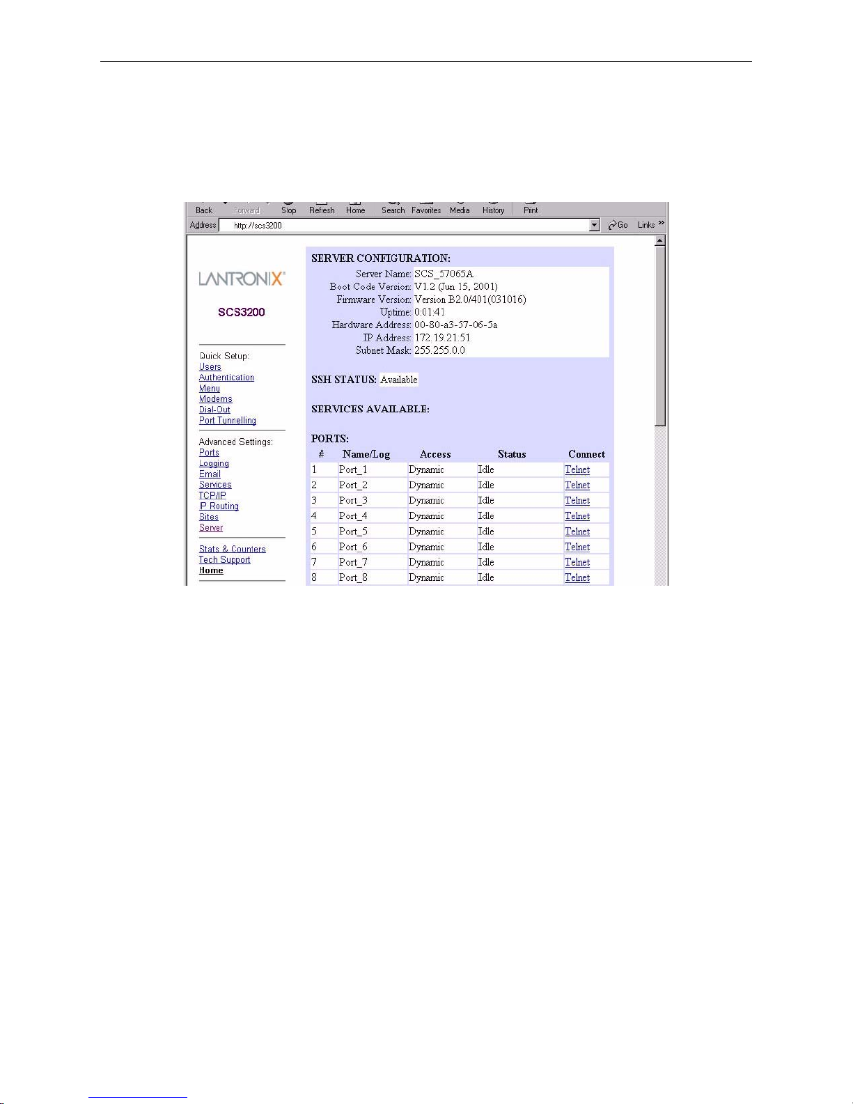
Getting Started Configuration Methods
From EZWebCon, select your device and choose Manage from the Actions menu.
OR
Type your SCS’s IP address or resolvable text name into your web browser’s URL/Location field.
Figure 2-2: The Web Browser Interface
Once you have connected and entered the login password (see Login Password on page 2-7), you can
configure important settings, view statistics, and update other Server information. Many of the
configurations discussed in this manual can be set using these web pages.
The on-board web browser can be disabled. See Set/Define Protocol HTTP on page 12-114 for more
information.
2.1.3 Command Line
To configure the SCS without EZWebCon or the web browser interface, you must enter configuration
commands at the command line. These commands should be entered when a port is in character mode,
which is when the Local> prompt is displayed.
To display the Local> prompt, do one of the following:
Connect a terminal to the serial console port and press the Return key until the prompt is displayed.
Note: The default serial port parameters are 9600 baud, 8 data bits, 1 stop bit, no
parity, and XON/XOFF flow control.
Establish a Telnet, SSH, or Rlogin connection to the SCS from a TCP/IP host. See Establishing
Sessions on page 6-8 for more information.
In EZWebCon, select Telnet To Device from the Actions menu.
2-2
Page 19

Getting Started Configuration Methods
2.1.3.1 Entering Commands
In examples throughout the manual, SCS commands and keywords are displayed in upper case for clarity.
They may be entered in upper, lower, or mixed case. When entering a string, such as a username or
filename, enclose the string in quotes; this will retain the case entered. If a string is not enclosed in
quotes, it will be changed automatically to all uppercase characters.
The Command Reference chapter (Chapter 12) displays the syntax of each command, including any
restrictions, known errors, and references to related commands. Optional parameters are enclosed in
brackets []. Required parameters are enclosed in curly braces {}; one and only one of those parameters must
be used. User-supplied parameters, such as a particular port number or host name, are shown in italics.
The SCS command completion feature will complete partially-typed commands for you. This feature can
save time and reduce errors if you’re entering a number of commands. To use command completion, type
part of a command, then press the space bar. The SCS will automatically “type” the remainder of the
command. If the partially-entered command is ambiguous (or if you are entering an optional string), the SCS
will be unable to finish the command and the terminal will beep.
Note: Command completion is disabled by default. To enable command completion,
refer to Set/Define Ports Command Completion on page 12-65.
All keys used for entering and editing commands are listed in Table 2-1.
Table 2-1: Command Editing Keys
Key Purpose
Return Executes the current command line
Delete Deletes the current character before the cursor
Ctrl-A Toggles insert mode (insert or overstrike).
Overstri ke is on by default.
Ctrl-D Logs out of the server
Ctrl-E Moves the cu rsor to the end of the line
Ctrl-H or Bac kspace Moves the cu rsor to the beginning of the line
Ctrl-R Redisplays the current command
Ctrl-U Deletes the entire current line
Ctrl-Z Logs out of the server
Left Arrow Moves the cursor left
Right Arrow Moves the cursor right
Up Arrow or Ctrl-P Recalls the previous command
Down Arrow or Ctrl-N Recalls the next command
!text Recalls the last command starting with text
!! Recalls the last command
2.1.3.2 Command Types
The following types of commands appear frequently throughout this manual. There are subtle differences
between each group of commands.
2-3
Page 20

Getting Started Configuration Methods
The Set and Define commands make configuration changes to your SCS.
Set Makes an immediate (but not permanent) change; the change will be lost when
the SCS is rebooted. To make the change permanent, you must also enter the
Save command (discussed on page 12-189).
Define Makes a permanent change, but the change doesn’t take effect until the SCS is
rebooted.
Define Port and Define SLIP settings take effect after the current user logs out.
Define Site takes effect when a site is started. Define Server, Define Telnet
Host, and Define Service settings take effect when the SCS is rebooted.
The Show, Monitor, and List commands display information about the SCS.
Show Displays the current settings. Current settings include those made using the Set
command but not yet defined or saved as permanent changes.
Monitor Displays current operating characteristics, which are updated every three
seconds until a key is pressed. Monitor commands may only be used by the
privileged user.
List Displays settings that will take effect the next time the SCS is rebooted.
Clear and Purge alter previously configured SCS settings.
Clear Removes a configured setting immediately, but does not make a permanent
change.
Purge Removes a configured setting permanently, but does not take effect until the
unit is rebooted.
Note: Purge Port will take effect as soon as the port is logged out, and Purge Site will
take effect when a site starts.
2.1.3.3 Restricted Commands
Some commands require privileged (superuser) status. To obtain privileged status, you must enter the
privileged password. See Privileged Password on page 2-8 for instructions on entering and editing the
privileged password.
By default, the SCS prompt changes from Local> to Local>> to reflect privileged user status.
2.1.3.4 Abbreviating Commands
When configuring the Server via the command line, you only need to enter as many characters as are needed
to distinguish the keywords from one another. For example, the following two commands are equivalent:
Local>> DEFINE PORT 2 BROADCAST ENABLED AUTOCONNECT ENABLED PARITY EVEN SPEED 4800
Local>> DEF PO 2 BRO EN AUTOC EN PAR E SP 4800
Figure 2-3: Abbreviating a Command
2-4
Page 21

Getting Started Rebooting
An abbreviation must be unique to the desired command. For example, if autoconnect was abbreviated as
auto, that auto could denote autobaud, autostart, or autoconnect. Be sure that any abbreviations are
unambiguous, such as autoc in the example above.
2.2 Rebooting
There are four ways to reboot the SCS:
From within EZWebCon, select Reboot from the Actions menu.
From the Server section of the web browser interface, check the Reboot Server checkbox. Then, click
the Update Server Settings button at the bottom of the page.
At the Local> prompt, issue the Initialize Server command.
Cycle power to the unit.
When the SCS is rebooted, any changes made using Set commands will be lost. To ensure that the changes
will be saved, use Define commands, or use the Save command after the Set command.
Before rebooting the SCS, log out any current user sessions (if possible). Disconnecting sessions may
prevent connection problems after the SCS is rebooted. If possible, warn users that the SCS will be going
offline by sending a Broadcast message.
2.2.1 Sending a Broadcast Message
Broadcast messages are sent to local users, but not remote networking users. Broadcasts can be sent to all
Server ports with the following command.
Figure 2-4: Broadcast Command
Local>> BROADCAST ALL "Server shutdown in 5 minutes."
2.2.2 Restoring Factory Defaults
Restoring factory default settings will erase all changes made since the SCS was shipped; the unit will
function as if it just came out of the box. To restore factory defaults, enter the Initialize Server Factory
command at the Local> prompt.
To perform a TFTP boot after restoring the factory defaults, you must enter the SCS IP and loadhost
information. (If a BOOTP server will provide this information, this step is not required.) Refer to your User
Guide for instructions.
2-5
Page 22

Getting Started Rebooting
When initialized, the SCS sets local authentication in the first precedence slot. For more information on
authentication and precedence, see Database Configuration on page 11-9.
2.2.3 Reloading Operational Software
The SCS stores its software in Flash ROM. The software controls the initialization process, the operation of
the SCS, and the processing of commands. The contents of Flash ROM can be updated by downloading a
new version of the operational software.
For instructions on reloading Flash ROM, refer to your Installation Guide.
2.2.4 Editing Boot Parameters
If the information that the SCS uses at boot time changes, you will need to change the SCS boot parameters.
Boot parameters include the following:
Loadhost (TCP/IP). The loadhost is the host from which the SCS operational software is downloaded
at boot time.
Backup loadhost (optional). Software is downloaded from a backup loadhost when the primary
loadhost is unavailable.
Software filename
RARP (may be enabled or disabled)
BOOTP (may be enabled or disabled)
Boot parameters are edited using Set/Define Server commands such as Set/Define Server Loadhost. All
available server commands are listed in Server Commands on page 12-111. Use the Define commands if
you want any changes to be saved after reboot.
Figure 2-5: Ed i ting the Loadhos t Address
Local>> DEFINE SERVER LOADHOST 192.0.1.8
2-6
Page 23
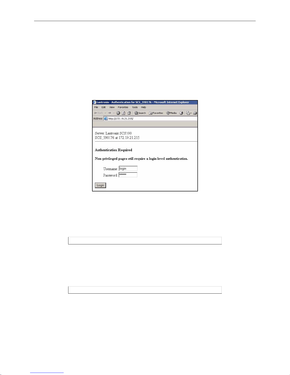
Getting Started System Passwords
2.3 System Passwords
The SCS has both a login password and a privileged password. These passwords have default settings which
should be changed as soon as possible. The following sections discuss each password in more detail.
2.3.1 Login Password
When you open the web browser interface for an SCS, you are prompted for the login username and
password. To control this setting, use the Server Login Password Required checkbox on the Server page.
Figure 2-6: Web Browser Au t h entication
When a serial port has the login password enabled, users must enter the correct password to access that
port’s Local> prompt. The default login username is login, and the default login password is access.
To change the login password, use the Set /Define Server Login Password command.
Figure 2-7: Defining the Login Password
Local>> DEFINE SERVER LOGIN PASSWORD badger
Note: The login password is case-insensitive, so it does not need to be enclosed in
quotes.
To enable the use of the login password on a particular port, use the following command:
Figure 2-8: Enabling the Login Pas s word
Local>> DEFINE PORT 3 PASSWORD ENABLED
Note: To enable the password on virtual ports, which are used for incoming
connections, use the Set/Define Server Incoming command.
Login passwords are also discussed in Character Mode Logins on page 11-1.
2-7
Page 24
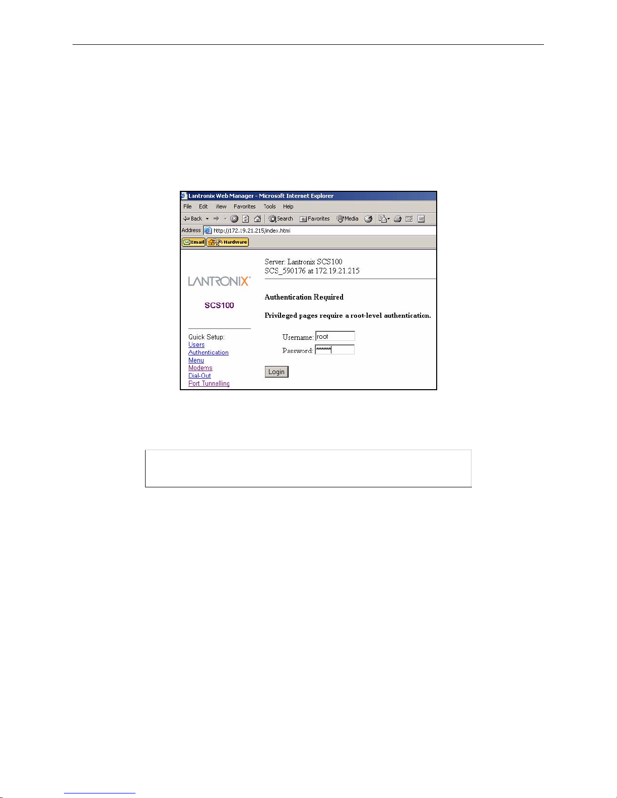
Getting Started System Passwords
2.3.2 Privileged Password
Changing any server, site, or port setting requires privileged user status. Use the default username, root, and
the default privileged password, system.
When you click on a link in the left navigation column of the SCS web browser interface, you are prompted
for the privileged username and password. Once you enter the password, you can access all of the
configuration pages.
Figure 2-9: Root-Level Authentication
If you are at the command line, become the privileged user by entering the following command.
Figure 2-10: Set Privileged Command
Local> SET PRIVILEGED
Password> system (not echoed)
Local>>
Note: The complete command syntax for Set Privileged is available on page 12-92.
2-8
Page 25

Getting Started Basic Configuration
To change the privileged password, use the Set/Define Server Privileged Password command ( dis c us s ed
on page 12-123). Figure 2-11 displays an example of this command.
Figure 2-11 : Changing the Privileged Password
Local> SET PRIVILEGED
Password> system (not echoed)
Local>> DEFINE SERVER PRIVILEGED PASSWORD hippo
Note: The privileged password is case-insensitive, so it does not need to be enclosed in
quotes.
2.4 Basic Configuration
The following sections discuss features that will identify and personalize each SCS.
2.4.1 Changing the Server Name
Each SCS is initially configured with a server name in the form of SCS_xxxxxx, where xxxxxx represents
the last three segments of its hardware address. However, you can give the Server a custom name of up to
16 alphanumeric characters using the following command.
Figure 2-12 : Changing the Server Name
Local>> DEFINE SERVER NAME "CommServer"
Note: The server name must be enclosed in quotes to preserve case.
2.4.2 Changing the Local Prompt
The prompt each user receives (usually a Local_xx> prompt, where xx is the port number) is configurable
in a variety of ways. For a basic prompt, enter a string similar to the following.
Figure 2-13: Configuring the Server P rompt
Local> SET SERVER PROMPT "Server> "
Server>
For a customized prompt, optional key combinations can be added to the prompt string. See Set/Define
Server Prompt on page 12-123 for more information. Placing a space after the end of the prompt is
recommended to improve readability.
Figure 2-14 displays a few examples of commands used to change prompts. In the examples, the first
command line results in the prompt used in the second command line, and so on.
Figure 2-14: Prompt Exampl es
Local> SET SERVER PROMPT "Port %n: "
Port 5: SET SERVER PROMPT "%D:%s: "
SCS:LabServ: SET SERVER PROMPT "%p%s_%n%P%% "
Port_5[NoSession]_5>%
2-9
Page 26

Getting Started Basic Configuration
2.4.3 Changing the Login Prompts
When a user logs into the SCS, he is prompted for a username, and sometimes a login password. By default,
the prompts are Username> and Password>. The prompts can be changed to be more like UNIX prompts
(login: and Password:) with the following command.
Figure 2-15: Enabling th e Alternate Lo gi n P rompt
Local> SET SERVER ALTPROMPT ENABLED
2.4.4 Setting the Date and Time
The SCS can calculate and save the local time, coordinated Universal Time (UTC, also known as Greenwich
Mean Time or GMT), standard and Daylight Savings timezones, and the corresponding number of hours
difference between UTC and the set timezone.
2.4.4.1 Setting the Clock
Use the Set/Define Server Clock command at the Local> prompt. Time should be entered in hh:mm:ss
“military format” as shown in the example below.
Figure 2-16: Setting the Cl ock
Local>> SET SERVER CLOCK 14:15:00 12/01/2000
2.4.4.2 Setting the Timezone
The SCS is configured to recognize a number of timezones. To display these timezones, use the Show
Timezone command at the Local> prompt. Set the timezone by using the Set/Define Server Timezone
command at the Local> prompt.
Figure 2-17: Setting the Timezon e
Local> DEFINE SERVER TIMEZONE AMERICA/PACIFIC
2-10
Page 27

Getting Started Basic Configuration
If your timezone is not listed, you will need to set it manually. Use the following information to set the
timezone:
A three-letter timezone abbreviation; for example, PST
The number of hours offset from UTC (Greenwich Mean Time); for example, -9:00
The time, day, and amount of any time changes (for example, daylight savings time information)
Note: Specifying time change information is optional.
Figure 2-18 shows an example of how to set the timezone.
Figure 2-18: Manual Ti m ezone Config uration
Local>> DEFINE SERVER TIMEZONE EST -3:00 EST 1 Mar Sun>=1 3:00 Oct lastSun 2:00
The first EST specifies that Eastern Standard Time will be used as the reference point. The second value of
-3:00 indicates that this timezone is 3 hours behind Eastern Standard Time. The third and fourth values, EST
and 1, specify that when a time change occurs the time will move forward one hour. The time change will
occur in March, denoted by Mar. The date that the time change will occur will be the Sunday (Sun) greater
than or equal to 1 (>=1), in other words, the first Sunday in the month. The 3:00 specifies that the time
change will occur at 3 o’clock.
The final three values of the command string represent the day and time when the time will revert to the
original time, in other words, when the time change will be reversed. The Oct and lastSun indicate that the
time will revert on the last Sunday in October. The time change will occur at 2:00.
2.4.4.3 Designating a Timeserver
The SCS regularly verifies and updates its setting with the designated timeserver. A timeserver is a host
which provides time of day information for nodes on a network. The SCS can communicate with either
Daytime or Network Timeserver Protocol (NTP) servers. For NTP, the SCS can periodically broadcast a
message asking for time information and wait for an NTP timeserver to reply (the Broadcast parameter),
periodically query a specific NTP timeserver (the IP ipaddress parameter), or just listen for NTP broadcasts
on the network (the Passive parameter).
To specify a timeserver, use the Set/Define IP Timeserver command.
Figure 2- 19: Defining Timeservers
Local>> DEFINE IP TIMESERVER DAYTIME 193.0.1.50
Local>> DEFINE IP TIMESERVER NTP PASSIVE
2.4.5 802.11 Configuration
This section applies only to the SCS200. Topics discussed in this section assume that you understand IEEE
802.11 wireless Ethernet concepts and architectures. If you do not, please refer to the IEEE 802.11 standard
or the documentation that came with your PC card or Access Point (AP).
Note: The SCS does not support PC card hot-swapping. Any time you insert a PC card
into an SCS PC card slot, you must reboot the SCS.
2-11
Page 28

Getting Started Basic Configuration
The following parameters should be configured only if you are using the SCS for 802.11 wireless Ethernet
networking and plan to use a wireless LAN PC card in one of the PC card slots. Users in countries other
than the United States must set the Region appropriately before using 802.11.
Not all configuration options will be available on all 802.11 cards. If you try to enter an option that is not
supported by your card, you will receive an Error message.
Any time you enable or disable 802.11 networking, you must reboot the SCS before the change takes effect.
Any other changes you request with the Set/Define 80211 commands will not take place until you have
entered the Set 80211 Reset command. You can enter the Show IP Counters command to see the current
802.11 settings.
To use the web browser interface to configure 802.11 settings, select the 802.11 link under the Advanced
Settings section.
2.4.5.1 802.11 Terms
The following acronyms are used in this section:
AP Access Point, a device that relays communications between one or more
wireless devices and possibly other devices on a network. APs are usually
connected to a physical network.
Note: If you are using an AP and WEP is not enabled, set the AP to accept Open System
Authentication. If WEP is enabled, set the AP to Shared Key Authentication. For
more information about WEP, see the definition below.
2-12
Page 29
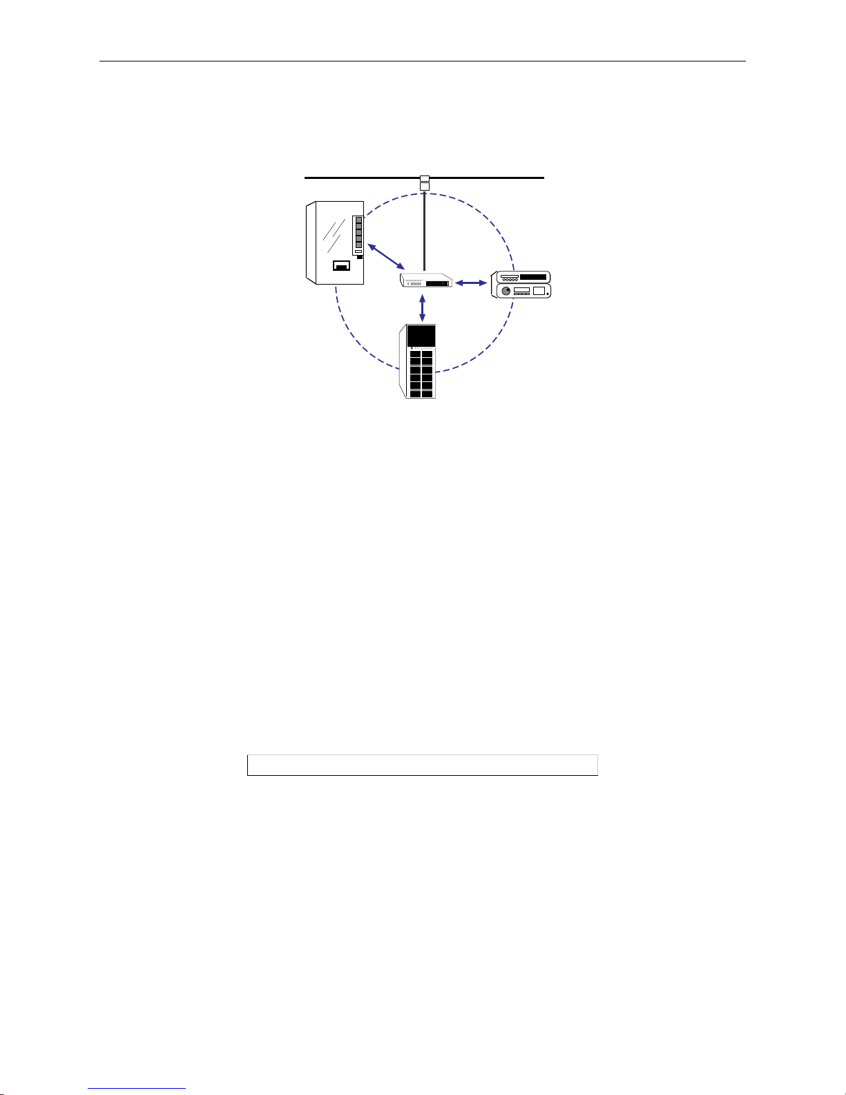
Getting Started Basic Configuration
BSS Basic Service Set (or Cell), a group of wireless devices that speak directly with
each other. A BSS may consist of at most one AP.
Figure 2-20: Simple Wireless Network BSS
AP
BSS
ESS Extended Service Set, a network consisting of one or more BSSs that share the
same ESSID. An ESS can contain multiple APs.
IBSS Independent Basic Service Set, a BSS with no APs. Devices work in an ad-hoc
networking mode.
WEP Wireless Equivalent Privacy, a form of encryption for wireless
communication.
2.4.5.2 Enabling 802.11 Networking
The SCS has 802.11 networking enabled by default. This allows the SCS to check for a compatible wireless
networking card at startup. If a compatible card is present, the SCS will use the wireless network and ignore
any wired Ethernet settings. If no compatible PC card is present, the SCS will use the 10/100BASE-T
Ethernet interface.
If you want the SCS to only look for a wired Ethernet connection, you must disable 802.11.
Figure 2-21: Disablin g 802.11
Local>> DEFINE 80211 DISABLED
Note: You must reboot the SCS after enabling or disabling 802.11 networking.
2.4.5.3 802.11 Region
When using 802.11 networking, you must make sure the SCS is configured for the correct regulatory
region. Configuring this option incorrectly may cause the SCS to broadcast on frequencies that are illegal
in your area. The factory default setting is correct for the United States; users in other countries should
change it to a value appropriate for their area before attempting 802.11 operation.
2-13
Page 30

Getting Started Basic Configuration
Other region settings are listed in Set/Define 80211 Region on page 12-30. In the following example, IC
sets the region to Canada.
Figure 2-22: Setting the 802.11 Region
Local>> DEFINE 80211 REGION IC
Local>> SET 80211 RESET
2.4.5.4 MAC Address
A MAC address is a unique identifier that distinguishes different devices on the 802.11 network. It is the
same as the unit’s hardware address. The SCS can be configured to use either the PC card’s MAC address
or its own internal MAC address (the default) with the Set/Define 80211 MAC Address command. For
seamless operation when switching between wired and wireless networking, use the SCS’s MAC address.
Figure 2-23: Configurin g the MAC Addre ss
Local>> DEFINE 80211 MACADDRESS CARD
Local>> SET 80211 RESET
or
Local>> DEFINE 80211 MACADDRESS SCS
Local>> SET 80211 RESET
2.4.5.5 Extended Service Set ID (ESSID)
Whenever there is more than one ESS in a wireless LAN architecture, each device needs to be told which
ESS it belongs to. The ESSID ensures that devices communicate with the right AP.
To tell the SCS which ESS it belongs to, enter the Set/Define 80211 ESSID command. The exact string you
enter will be determined by the settings of the AP with which you want the SCS to communicate.
Figure 2- 24: Configuring the ESS ID
Local>> SET 80211 ESSID “floor3”
Local>> SET 80211 RESET
Setting the ESSID to none (Set/Define 80211 ESSID None) allows the SCS to associate with any AP within
range.
2.4.5.6 Network Mode
There are two types of 802.11 networks: ad-hoc and infrastructure. In an ad-hoc network, devices
communicate directly with one another on a peer-to-peer basis. In an infrastructure network (the default),
several devices communicate with one or more APs. The APs may or may not be connected to a physical
Ethernet network. You must tell your SCS which type of network is present with the Set/Define 80211
Network Mode command.
Figure 2-25: Configuring the Network M ode
Local>> DEFINE 80211 NETWORKMODE ADHOC
Local>> SET 80211 RESET
or
Local>> DEFINE 80211 NETWORKMODE INFRASTRUCTURE
Local>> SET 80211 RESET
The network mode setting relates to the channel setting, explained next.
2-14
Page 31

Getting Started Basic Configuration
2.4.5.7 Channel
The frequency band allocated to 802.11 wireless communications is subdivided into different channels to
allow subnetworking. Your SCS needs to know which channel it should use for communications—the
channel will be the same as the one being used by the local AP. The default setting, Any, causes the SCS to
use the same channel used by the strongest AP with the same ESSID.
For infrastructure network mode, you should set the channel to Any so that the SCS can synchronize with
an AP. For Ad-Hoc network mode, you should set a specific channel number so that the SCS can start a new
IBSS if needed. When the channel is set to Any, the SCS can only join an existing IBSS.
Figure 2-26: Configuring the 802.11 Cha nnel
Local>> DEFINE 80211 CHANNEL 7
Local>> SET 80211 RESET
2.4.5.8 WEP
Some 802.11 cards can be set with a WEP key, which will encrypt any data you transmit through wireless
communication. To enable WEP, enter the following command:
Figure 2-27: Enabling WEP
Local>> DEFINE 80211 WEP ENABLED
Local>> SET 80211 RESET
When WEP is enabled and a WEP key is set, the SCS will only connect to an AP (in infrastructure mode)
or communicate with other ad-hoc peers (in ad-hoc mode) that have been programmed with the same WEP
key as the SCS. For a key to match, both the key data and the index number must be identical.
Enter a WEP key if you have not previously done so. The key can be either 40-bits or 128-bits. Each key is
also assigned an index number, which is an integer between 1 and 4.
Figure 2-28 : Setting the WE P Key and Index Num ber
Local>> DEFINE 80211 WEP KEY 26-e4-97-db-1f
Local>> DEFINE 80211 WEP INDEX 3
Local>> SET 80211 RESET
The SCS will receive both encrypted and unencrypted traffic. You can disable the reception of unencrypted
traffic and accept only frames encrypted with its WEP key by entering the following command:
Figure 2-29: Disab l i n g WE P Unencrypte d Tr a f fi c Reception
Local>> DEFINE 80211 WEP RECEIVE ENCRYPTED
Local>> SET 80211 RESET
2-15
Page 32

Getting Started Configuration Files
2.5 Configuration Files
Once you have configured one SCS, you can create a configuration file from those settings and download
that file to other devices. A configuration file is a series of commands used to automatically configure an
SCS. By using a configuration file, you save time that would otherwise be spent manually entering
commands. You can also update the configuration of many devices simultaneously, ensuring that each
device is configured the same. You can download a file manually, or configure the SCS to automatically
download a file each time it boots.
EZWebCon can automatically translate your current SCS configuration into a configuration file, which can
then be downloaded through EZWebCon to other devices. Refer to EZWebCon’s online help for more
information.
The rest of this section describes how to create and use configuration files at the command line.
2.5.1 Creating a Configuration File
To create a configuration file without EZWebCon, you must manually enter each command in the file.
1 On your host, enter a series of SCS commands in a text file, one command per line. Privileged
commands may be included; when the file is downloaded, the commands will be executed as if a
privileged user was logged into the SCS.
Capitalization of commands is optional. If a string (such as a filename) is entered, it must be
enclosed with quotes in order to preserve the case. To include a comment in the file, preface the
line with a pound (#) character. These lines will be ignored.
If Define Server commands are included in the file, they will not take effect until the SCS is rebooted.
Define Port commands will not take effect until the specified ports are logged out. Define Site
commands will take effect when the specified site is started.
The configuration file must not contain any initialization commands (such as Initialize Server).
Because the file is read when the SCS boots, a “reboot” command in the file would cause the SCS to
boot perpetually. You would then have to flush the NVR to correct the error.
2 Test the configuration file. To test the file, use the Source command, discussed on page 12-131.
An example of a configuration file is displayed below.
Figure 2-30: Configuration File
DEFINE PORT 2 SPEED 9600
DEFINE PORT 2 PARITY NONE
# The following commands set up the ports:
DEFINE PORT 2 ACCESS DYNAMIC
2-16
Page 33

Getting Started Configuration Files
2.5.2 Using a Configuration File
A configuration file can be downloaded from a TCP/IP host (via TFTP). Ensure that TFTP downloading is
enabled on your host and place the configuration file in a download directory.
To download a configuration file to the SCS using TFTP, use the Source command.
Figure 2-31: Downloading From a TFTP Host
Local>> SOURCE “labsun:start.com”
If the configuration file must be downloaded each time the SCS boots, specify the filename using the Set/
Define Server Startupfile command. A TCP/IP filename must be specified in host:filename format, where
host is an IP address.
Note: If lower-case or non-alphabetical characters are used, the filename must be
enclosed in quotes.
For example, to download the file config.sys from TCP/IP host 192.0.1.110, use the following command:
Figure 2-32: Downloading From a TCP/IP Host
Local>> DEFINE SERVER STARTUP "192.0.1.110:config.sys"
Note: The SCS is not usable during download attempts.
If the SCS has a nameserver defined, a text name may be specified as a TCP/IP host name. The SCS will
attempt to resolve the name at boot time; if it cannot resolve the name, the download will fail. To designate
a nameserver, see Set/Define IP Nameserver on page 12-39.
During its boot sequence, the SCS will load its operational code first, then attempt to download the
configuration file. If the attempt to download the configuration file is unsuccessful, the SCS may re-attempt
the download. By default, the SCS will make a total of six attempts to download the file (one initial attempt
and five re-attempts). To change this setting, use the Set/Define Server Startupfile Retry command.
Figure 2-33: Setting Number of Download Attempts
Local>> DEFINE SERVER STARTUPFILE "TROUT\SYS:\LOGIN\config.sys" RETRY 10
If Retry is set to zero, the SCS can no longer be used; it will wait indefinitely for the configuration file to
download.
2-17
Page 34

Getting Started Disk Management
2.6 Disk Management
The SCS contains three filesystems:
/flash Flash is rewriteable memory that allows you to customize your SCS. Any data
that you want the SCS to save after it is rebooted should be stored on the Flash
disk.
/ram The RAM disk stores temporary information. The SCS will hold information
stored on this disk until it is powered off or rebooted. At startup, the RAM disk
will be empty. FTP connections to the SCS automatically use the RAM disk as
the default working directory. The RAM disk size is 512 Kbytes.
/rom The ROM disk is read-only and cannot be modified by users.
In addition to the onboard Flash disk, the PC card slots on the SCS200 and SCS400 can be used with ATA
flash cards and hard-drive PC cards for portable storage of local files.
In some instances, you may need to edit a file on another machine and then FTP it to the SCS. Use your FTP
client software to form a connection to the SCS (using the SCS’s resolvable name or IP address). You can
then transfer files to (put) and from (get) the /flash, /pccard, and /ram disks.
2.6.1 Flash Disk
The Flash disk (/flash), rewriteable memory, should be used to hold any data that you want the SCS to save
after it is rebooted. Because power glitches can affect data integrity, important files on /flash should be
backed up on an ATA flash card or on another server.
The Disk commands can be used to manage files on the Flash disk. For example, the following command
creates a new directory on the Flash disk that could be used for custom application files:
Figure 2-34: Creating a New Directory on the Flash Disk
Local>> DISK MKDIR /flash/customapps/
To view all of the files and directories currently on the Flash disk, enter Disk ls with or without flags. The
following example will display all the files as well as the modification date, size, owner, and permissions:
Figure 2-35: Listing Di rectory Contents
Local>> DISK LS -l /flash
The complete syntax of the Disk command is available on page 12-182.
2.6.2 ATA Cards
Once an ATA flash disk or hard-drive PC card is formatted (using the Disk Format /pccard command), the
card can be used the same as the on-board Flash disk. Files on the card can be references as “/pccard1/
directory/filename.”
Note: The SCS does not support PC card hot-swapping. Any time you insert a PC card
into an SCS PC card slot, you must reboot the SCS.
2-18
Page 35

Getting Started Disk Management
The Disk commands described above and on page 12-182 can also be used for file management on the flash
card. For example, to back up a Flash disk file (data.txt) to an ATA card, use the following commands to
create a backups folder on the card and to copy the desired file into that folder:
Figure 2-36: Backing Up Files To a Flash Card
Local>> DISK MKDIR /pccard1/backups/
Local>> DISK CP /flash/customapps/data.txt /pccard1/backups
The maximum number of files and directories (total sum) that can fit on the card is a function of the size of
the card: divide the size of the card by 5k (5120 bytes). This assumes that the average size of all the files
that will fill up the card will be smaller than 5k.
Data can be corrupted if power is lost in the middle of a write (for example, if the cord is pulled). If the Disk
Sync command is issued and power is removed after the command is completed, data will be stored
correctly on the card. Likewise, there should be no problems with data integrity if the Initialize Server
Delay 0 command is used to reboot the unit.
2-19
Page 36

3: Console Server Features
2)
This chapter describes how to configure your SCS to serve as a console server. The SCS features both inband management for access to connected devices over IP (e.g. through Telnet and SSH connections
directly to the SCS), and out-of-band management for access through a connected modem.
This chapter is divided as follows:
Overview of Console Servers on page 3-1 introduces the functions of a console server.
Event Port Logging on page 3-2 describes how to save idle serial data in an easily accessible log file
Email Alerts for Serial Events on page 3-3 shows how to send the serial log via email.
Configuring Menu Mode on page 3-4 discusses the options for configuring SCS menus.
Login Banner Pages on page 3-8 covers in-band and out-of-band management options.
Serial Port Configurations on page 3-14 describes optimal serial port settings.
Most of these features are discussed in more detail in the IP, Ports, and Security chapters.
3.1 Overview of Console Servers
The SCS can be connected to the serial console ports of a variety of devices. You can then manage these
devices remotely either over an IP network or through a dial-up modem connection.
Figure 3-1: Console Server Setup
Lantronix
Conventional
Phone
Lines
Switch
Router
File Server
UPS
Console Management
Console
Server
ETS16PR
2143658
7
Phone
Line
receive
transmit
1091211141316
powerlink100okactivity
reset
10/100
# aui
15
Network
Switch
Router
File Server
UPS
UNIX Server
UNIX Server
Serial (RS-23
Phone Line
Network
3-1
Page 37

Console Server Feature s Event Por t Logging
3.2 Event Port Logging
Port logging saves all idle data from an SCS serial port in a log file. This log file can be accessed by a system
administrator after a system crash, and can provide valuable information about the cause of and solution for
any problems with the attached serial device.
If email notification (discussed in Email Alerts for Serial Events on page 3-3) is enabled, the serial log can
be sent via email to the system administrator.
3.2.1 Enabling Port Logging
Enable port logging with the Set/Define Ports Serial Log command. This command sets the file size for
the log file, which can be up to 250 Kbytes. To disable the log file, enter a file size of 0.
Figure 3- 2: Sav i ng S e rial Data to a Logfile
Local>> DEFINE PORT 2 SERIALLOG LIMIT 200
Note: This command sets port access to Access Remote.
The log file is stored on the SCS /ram disk in the form /ram/Port_xx.log where xx is the port number. When
the file reaches its specified limit, it is truncated to half its current size and begins logging again. The oldest
data is discarded.
When the SCS is rebooted, the data stored in the log file is lost.
3.2.2 Viewing the Port Log
This section describes three methods for retrieving port logs.
3.2.2.1 Telnet/Serial Login
To retrieve the port log using Telnet, SSH, or terminal login:
1 At a Local_n >prompt, type disk ls to see the files. The file is Port_nn by default, where nn is the
port number.
2 To view the entire log, type disk cat port_nn.log.
Note: You can use other Unix commands, such as tail and top.
3.2.2.2 Web Interface
To retrieve the port log using the web browser interface:
1 Open the web browser interface and http to the IP address or hostname of the SCS. The SCS Home
page displays. If logging is enabled, the port name is a link.
2 Click the link to open the file in the default text viewer.
3.2.2.3 FTP
To retrieve the port log using an FTP session:
3-2
Page 38

Console Server Features Email Alerts for Serial E vents
1 FTP to the SCS.
2 Type ls to get a listing of log files.
3 “Get” or “mget” a copy of the log file (for example., # mget Port_1.log).
3.3 Email Alerts for Seri al Events
Once a port is configured for port buffering (as described in Event Port Logging on page 3-2), you can
enable email notification. This feature triggers an email if the connected device reboots or otherwise
produces a burst of console output of 20 or more characters.
The port buffers incoming data for up to 25 seconds or until the log file reaches1500 bytes before sending
the email, which contains the current contents of the log file. Any data that comes in after that 25 seconds
will be saved in the file, but not included in that email. Email can not be sent from the same port more than
once every 10 minutes.
The email sent by the SCS also includes a URL that refers to the serial log file directly, so you can open it
in an email client or web browser. You will need to enter the system login password to access the file.
Note: If the HTTP server has been disabled with the Set/Define Protocol HTTP
command, you will not be able to use the URL to access the log file.
Each port’s email settings can be separately configured, or a default configuration can be created that will
be used for all email notifications. An emailsite stores the information necessary for email notification. The
only possible names for emailsites are portxx, where xx is a serial port number, or default. Settings for the
default emailsite will be used for any that are missing in the port-specific files.
Use the Define Email commands to configure each emailsite with features such as an email address for the
email to be sent to, a from line, a subject line, an SMTP mailhost, and a reply-to address.
The following example configures an emailsite for the second serial port.
Figure 3-3: Configuring an Email Site
Local>> DEFINE EMAIL port2 TO “admin@strut.com”
Local>> DEFINE EMAIL port2 FROM “Conserv2”
Local>> DEFINE EMAIL port2 SUBJECT “System Crash”
Local>> DEFINE EMAIL port2 MAILHOST “mail.strut.com”
Local>> DEFINE EMAIL port2 REPLYTO “managers@strut.com”
Dynamic print variables can be used with all of these command strings. For a complete list of available
variables, see Define Email on page 12-55.
To enable email notification for a port, use the Define Ports Event Email Serialdata command. This
command also sets the port’s access to Access Remote.
Note: Email notification only works on ports that have port buffering enabled.
Local>> DEFINE PORT 2 EVENT EMAIL SERIALDATA ENABLED
Figure 3-4: Enabling Email Notification
3-3
Page 39

Console Server Features Configuring Menu Mode
The List Email command can be used to show the emailsite configurations for one or more emailsites.
If network logging is enabled (Set/Define Logging Network Enabled), any errors that occur during email
notification are stored in the system log. System logging is discussed in Chapter 11, Security.
3.4 Configuring Menu Mode
When a port is in menu mode, users who log into the port will be presented with a list of menu options. Their
choices are limited to those displayed in the menu, as they will not be permitted to enter text commands.
Figure 3-5: Sample Menu
Lantronix Console Server
1) Cisco Router
2) Sun Server
3) Linux Server
Enter Selection:
Menus can be configured one of two ways: by entering title and item entries individually with the web
browser interface or at the command line, or by creating a menu configuration file.
4) Local> Prompt
5) Logout
6)
To enable menu mode on a particular port, use the Set/Define Ports Menu command.
Figure 3-6: Enabling Men u M ode on a Port
Local>> DEFINE PORT 2 MENU ENABLED
To display the current menu, use the Show/Monitor/List Menu command. If you are using a menu
configuration file, this command will not work—you must view that file to see the menus.
3.4.1 Menu Configuration at the Command Line
Use the Set/Define Menu command to create entries for your menu. For each menu entry, specify the
option’s numbered position in the table, the entry description that will be displayed in the menu, and the
actual command invoked when the user chooses that option. Enclose option and command names in
quotes.
Figure 3-7: Adding a Com m an d E ntry
Local>> DEFINE MENU 2 “Sun Server” “CONNECT LOCAL PORT_2”
It is a good idea to add a command to the menu that allows the user to log out of the server. The Exit
command only works in menu mode. It allows users to return to the Local> prompt on the SCS on which
the menu was configured. It is helpful to include this command in your menus until you have fully tested
them—otherwise there is no way for users on menu mode ports to return to the Local> prompt.
Local>> DEFINE MENU 5 “Exit” “Logout”
Figure 3-8: Adding a Log out Command
3-4
Page 40

Console Server Features Configuring Menu Mode
3.4.2 Menu Configuration Files
If you need to configure menus for multiple sets of users, you should create a menu configuration file. These
files provide more flexibility than the command line options and are easier to use when setting up larger
menus. The file is typically stored on the SCS flash disk (/flash).
Each menu in a configuration file is associated with a group. Each group consists of one or more users. One
group can include a user default, meaning that menu will be used for any users not explicitly in an other
group. Only one group can include the default user.
Follow the steps below to create a menu configuration file:
1 Start a new text file on a host other than the SCS. Once the file is complete, you will FTP it to the
SCS’s /flash disk. The /flash disk and the Disk commands are discussed in detail on page 2-18.
2 Define up to 10 groups of users. Each group, listed on separate lines, will later be assigned a specific
menu. Do not leave any whitespace between each name—the names should be separated by commas.
GROUP austin = sandy,dave,bob,kathy,default
GROUP admin = admin
Note: A space must be included on both sides of the = when defining the groups, as
shown in the example above. Also, remove any extra spaces from the end of each
line, as they will cause the menu parsing to fail.
If desired, you can use wildcards in usernames. To match a single character, use
a question mark (?), and to match any number of characters, use an asterisk (*).
3 Begin defining the menus. Start by assigning a menu to a specific group.
MENU austin
Then, assign the menu a title (up to five lines). This string will appear at the top of the menu. You can
use dynamic print variables in the title, which will appear appropriately when the menu is viewed.
You can include up to 5 lines of title information per menu.
TITLE “Lantronix Console Server”
Note: For a list of dynamic print variables, see Set/Define Menu on page 12-112.
4 Define the items that will appear in the menu. The items will be numbered in the order entered. Up to
36 items can be defined in one menu.
ITEM "Cisco Router" "telnet 192.0.1.250"
ITEM "Sun Server" "telnet 192. 0.1.251"
ITEM “Linux Server” “connect local po rt_4”
ITEM “Exit” “Logout”
ENDMENU
End the Menu with the line ENDMENU.
3-5
Page 41

Console Server Features Configuring Menu Mode
5 After ENDMENU, you can go on to define more menus for other groups of users.
MENU admin
TITLE “Lantronix Console Server”
ITEM “Cisco Router” “telnet 192.0 .1 .2 50"
ITEM “Exit” “Logout”
ENDMENU
Figure 3-9 shows what the above entries would look like in the completed menu configuration file:
Figure 3-9: Completed M e nu Configuration File
GROUP austin = sandy,dave,bob,kathy,default
GROUP admin = admin
MENU austin
TITLE “Lantronix Console Server”
ITEM "Cisco Router" "telnet 192.0.1.250"
ITEM "Sun Server" "telnet 192.0.1.251"
ITEM “Linux Server” “connect local port_4”
ITEM “Exit” “Logout”
ENDMENU
MENU admin
TITLE “Lantronix Console Server”
ITEM “Cisco Router” “telnet 192.0.1.250"
ITEM “Exit” “Logout”
ENDMENU
6
FTP the file to the SCS /flash disk.
To use the menu configuration file, enter the following command:
Figure 3-10: Using a Configuration Fi l e
Local>> SET MENU FILE /flash/menu.txt
Using Set with the above command will automatically parse the file for correctness. You can then
permanently set the file with the Define Menu File command. For more information on this command, see
Set/Define Menu on page 12-112.
Once the file is set and stored on the /flash disk, a user logging into the SCS will be presented with the
appropriate menu. The menu configured above, for one of the defined users (sandy, dave bob, kathy,
default), would look like the one shown below:
Figure 3-11: Menu Example
Lantronix Console Server
1) Cisco Router
2) Sun Server
3) Linux Server
4) Exit
Enter Selection:
3-6
Page 42

Console Server Features Configuring Menu Mode
3.4.3 Nested Menus
Nested menus are file-based menus that allow you to nest submenus within a menu file. Submenus have to
appear in the file before the menu that references them.
To use submenus, specify SUBMENU instead of MENU for the start of a new menu block. Then from a
different menu, include an action of GOTOMENU to jump to the submenu. One or more of the submenu
items can include an action of RETURNMENU to return to the top-level menu for the current user. After
Selecting an Action from the submenu, the user is returned to the top-level menu.
Following is an example of how to nest a menu.
Figure 3-12: Nested M enu Example
SUBMENU consoles
TITLE “This is the console submenu”
ITEM ...
ITEM “Return to Main Menu” “RETURNMENU”
ENDMENU
MENU main
TITLE “Welcome to Menuing”
ITEM ...
ITEM “Select a console connection” “GOTOMENU consoles”
ENDMENU
3-7
Page 43

Console Server Feature s Login Banner Pages
3.5 Login Banner Pages
Banner pages allow you to display text messages to users before and after authentication. Banner text
information is taken from two files named prelogin.txt and postlogin.txt stored in the /ram or /flash
directory on the SCS. The SCS does not store or display files stored in the /ram directory after rebooting.
To implement login and logout banner text:
1 Create text files with the desired text name prelogin.txt and/or postlogin.txt.
2 FTP to the IP address of the SCS.
3 Log in with the username root and enter the privileged password (system by default.)
4 Change directories to /flash or /ram.
5 “Put” the text files into the desired directory.
6 Reboot the SCS.
Subsequent users logging in or out of the SCS see the text in the prelogin.txt and postlogin.txt files,
respectively. The standard company/product/version banner displays if either of these two files is not
present in the SCS.
3.6 Managing the Attached Devices
You can manage the SCS’s connected serial devices over a network connection or through a modem
connection. Both of these methods ensure that the SCS and its attached serial devices are always accessible
and manageable, even in critical situations.
3.6.1 In-Band Management
The SCS provides TCP/IP socket connections to its serial ports. A TCP session to port 30xx, where xx is the
serial port number, will form a raw TCP/IP connection to that serial port. A connection to port 20xx provides
Telnet IAC interpretation.
Figure 3-13: T elnet IAC Co nnection to th e Second Serial Port
% telnet 192.0.1.66 2002
To connect to a specific SCS port using SSH, use socket number 22xx, where xx is the port number. The
syntax for an SSH connection depends on your client software. SSH is discussed in SSH Sessions on page
6-10.
Figure 3-14: Example of an SSH Connection to the Second Serial Port
% ssh -p2202 192.0.1.66
3-8
Page 44

Console Server Feature s Managing th e Attached Dev i ces
3.6.2 Out of Band Management
To ensure that you can manage attached equipment even if there are network problems, the SCS provides
an out-of-band management feature. If you have a modem connected to one of the SCS serial ports, you can
access and manage the SCS via a dial-in modem connection.
Instructions on modem configuration are available in Chapter 9, Modems.
To dial-in to the SCS,
1 Open a terminal emulator such as Hyperterminal
2 Dial the phone number for the modem attached to the SCS.
3 When the connection is complete, press <CR>.
The username and password prompt appear.
4 Enter your username and password.
You are now logged in to the SCS serial port.
For instructions on dialing in with PPP, read Chapter 4, Basic Remote Networking. Instructions on attaching
modems are included in Chapter 9, Modems.
3.6.3 Connecting from the Local> Prompt
Before you connect to a serial port, make sure that you have a way to exit the connection. If your keyboard
does not have a break key, specify an equivalent using the Set/Define Ports Local Switch command.
Figure 3-15: Specifying Local Switch
Local>> DEFINE PORT 2 LOCAL SWITCH ’
Then, use the Set/Define Ports Break command to instruct the break key to bring you back to Local>
prompt when pressed during a session.
Figure 3-16: Configuring Break Key Processing
Local>> DEFINE PORT 2 BREAK LOCAL
To connect to a serial port from the SCS Local> prompt, use the Connect Local command.
Figure 3-17: Connect Local Command
Local> CONNECT LOCAL PORT_2
Once within the session, you can exit by pressing the break key. This returns you to the Local> prompt. For
more information on available session options, see Port-Specific Session Configuration on page 8-4.
3.6.4 Serial Break Handling
This section describes how to specify serial breaks and alternate break (AltBreak) sequences.
3-9
Page 45

Console Server Feature s Managing th e Attached Dev i ces
3.6.4.1 Serial Breaks
Break conditions originating from serial connections are controlled on a per port basis. Break conditions
originating from incoming Telnet and SSH connections are based on the settings for port 0, the network
(template) port.
To define where the break condition will be processed, use the Set/Define Ports Break [ local | Remote ]
command for each serial port and port 0.
The default break sequence for port 0 is <Ctrl+Y>. There is no default break sequence for the serial ports.
3.6.4.2 Alternate Break Sequences
You can specify an alternate break (AltBreak) character for use with terminals that cannot natively generate
a break condition and for Telnet or SSH clients that cannot generate break IAC sequences. The syntax for
specifying an AltBreak sequence is Set/Define Ports Break[ <char> | None ], where <char> is a single
character enclosed in quotes. You can specify non-printable characters using the notation \xx, where xx is
the hexadecimal representation for the desired character. The Show/Monitor/List Ports command displays
the current setting.
3-10
Page 46

Console Server Feature s Managing th e Attached Dev i ces
The table below shows some examples to help you understand how the SCS handles breaks.
Table 3-1: Examples of Alternate Break Sequences
If And Then
The user Telnets to a re mote network host
from a loca l (S CS ) se ri a l po rt
The user issues a Connect Local co mmand
to another serial port from a local (SCS)
serial port
The user Telnets to the SCS Local> prompt
and
issues a Connect Local command to a
serial port
The serial port has
Break = Local
The serial port has
Break = Remote
The user’s serial
port has Break =
Local
The user’s serial
port has Break =
Remote
Tem plate port has
Break = Remote
T emplat e port 0 h as
Break = Local
The AltBreak sequence returns
the user to a local (SCS)
command pr ompt.
The AltBreak sequence causes
the SCS to transmit a Telnet
Break IAC sequence to the
remote host.
The AltBreak sequence returns
the user to a local (SCS)
command pr ompt.
The AltBreak sequence generates
a break condition to the target
port. (The targe t po rt ’s break
settings do not a ppl y or a f fe ct thi s
situation.)
The AltBreak sequence returns
the user to a local (SCS)
command pr ompt.
The AltBreak sequence generates
a break condition to the target
port. (The targe t po rt ’s break
settings do not a ppl y or a f fe ct thi s
situation.)
The user on an SCS serial port makes an
SSH connection to a network host
At the Local> prompt, the u se r Telnets to
the SCS
and
receives the default AltBreak character
from template por t 0
The serial port has
Break = Local
The serial port has
Break = Remote
T emplat e port 0 h as
Break = Local The AltBreak sequence does
T emplat e port 0 h as
Break = Remote
The AltBreak sequence returns
the user to a local (SCS)
command pr ompt.
Nothing happens as there is no
way to propagate a break across
an SSH connection.
nothing because breaks are
ignored at the Local> prompt.
3-11
Page 47

Console Server Feature s Managing th e Attached Dev i ces
Table 3-1: Examples of Alternate Break Sequences
If And Then
The user forms a Telnet or SSH connection
to the SCS
and
Issues a Connect Local co mmand to
connect to port 7
(Note that port 7’s break settings are not
applicable.)
and
receives a default AltBreak char acter from
port 0
The user forms a Telnet connection from a
host to port 7 on the SCS using socket 2007
and
the AltBreak character has been defined on
port 7
and
the AltBreak character is detected in the
data stream from the host
(Note that the 20xx range of sockets
performs Telnet IAC interp retation.)
The user forms a Telnet connection from a
host to port 7 on the SCS using socket 2007
and
the AltBreak character has been defined on
port 7
and
the a break condition is detected on the
serial port
(Note that the 20xx range of sockets
performs Telnet IAC interp retation.)
The template port
(port 0) ha s Break
= Local
The template port
has Break =
Remote
Port 7 has Break =
Remote
Port 7 has Break=
Local
Port 7 has Break =
Remote
Port 7 has Break =
Local
The AltBreak sequence returns
the user to a local (SCS)
command pr ompt.
A break co ndi tio n i s ge ner ated on
port 7.
A serial break condition is
generat e d on th e po rt .
Nothing happens.
A T el net Br eak IAC is sent on th e
networ k co nnectio n .
Nothing happens.
3-12
Page 48

Console Server Feature s Managing th e Attached Dev i ces
Table 3-1: Examples of Alternate Break Sequences
If And Then
The user forms a TCP connection from a
host to port 7 on the SCS using socket 3007
and
The AltBreak character has been defined on
port 7
and
The AltBreak character is detected in the
datastream from the host
(Note tha t the 30x x r an ge o f s ocke ts is 8-bit
clean.)
The user forms a TCP connection from a
host to port 7 on the SCS using socket 3007
and
The AltBreak character has been defined on
port 7
and
A break condition is detected on the serial
port
(Note tha t the 30x x r an ge o f s ocke ts is 8-bit
clean.)
Port 7 has Break =
Remote
Port 7 is set to
Break = Local
Port 7 has Break =
Remote or
Port 7 has Break =
Local
A serial break condition is
generat e d on th e po rt .
Nothing happens.
Nothing happens because there is
no way to propogate a break
across an 8-bit clean conne ction.
3-13
Page 49

Console Server Features Serial Port Configurat i ons
3.7 Serial Port Configurations
This section describes several available configuration and management options for the SCS serial ports.
These configurations help ensure easy management of the attached devices.
3.7.1 Enabling the Incoming Password
The Set/Define Ports Password Incoming Enabled command requires users who Telnet or SSH directly
to the target serial port to provide their username and password pair, which will be checked against the
configured authentication databases, before gaining access to the serial port.
Figure 3-18: Enabling the Incomin g Password
Local> DEFINE PORT 2 PASSWORD INCOMING ENABLED
The login password is discussed in System Passwords on page 2-7.
3.7.2 Setting the Port Access Mode
A port’s access may be set to one of the following: dynamic, local, remote, or none. Dynamic (the default)
permits both local and remote logins, local allows only local logins, and remote permits only remote logins.
None prevents all incoming and outgoing connections, rendering the port unusable.
When using the SCS as a console server, you will want to set most ports to Remote access so any serial data
from the attached device will not accidentally cause the SCS to create a local connection and make that port
unavailable.
Note: When port buffering is enabled, the port access is automatically changed to
Remote access.
To configure access to a port, use the Set/Define Ports Access command.
Figure 3-19: Setting Remote Access for a Serial Port
Local>> DEFINE PORT 2 ACCESS REMOTE
3.7.3 Displaying Port Status
Use the Show Ports Counters and the Show Ports Status commands to display current serial port
information. Counters displays the port’s local and remote accesses as well as any communication errors.
The Status parameter shows information regarding the port’s serial connections, including the current flow
control state and the state of the DSR and DTR signals.
3.7.3.1 SNMP Queries
You can also check a port’s status by sending an SMNP query. Parts of the MIB-II, RS-232 MIB, and
Character MIB cover individual serial port status. Use an SNMP management application to query the SCS
for the port status.
For more information on SNMP, see , .
3-14
Page 50

4: Basic Remote Networking
R
n
R
The SCS allows remote users to securely connect to local network resources, or two Local Area Networks
(LANs) to connect to each other. This chapter describes how to initialize, maintain, and disconnect
individual remote user dial-ins and LAN to LAN remote connections.
After completing this chapter, you should be able to configure the SCS to support the following types of
connections:
Incoming remote user dial-in
Incoming character, PPP, and SLIP modes
Basic outgoing LAN to LAN using PPP
The functionality described in this chapter may not meet all of your performance or network security needs.
If your network requires more complex configuration, or if you are not using modems, refer to Chapter 5,
Additional Remote Networking, for additional configura tion instructions.
4.1 Remo te Connection Types
The SCS is capable of two types of remote networking connections: LAN to LAN and remote node.
4.1.1 Remote Dial-in
A remote user, or remote node, connection allows remote dial-in users to securely access network
resources. Users can access network file servers, send or receive email, use the Internet, or remotely
administer equipment. For example, a laptop user on a business trip may wish to access files from a
network’s file server. Using a modem, the laptop could dial the SCS, form a connection, and download the
files as if the laptop were directly connected to that network.
Figure 4-1: Remote Dial-In Example
Modem
Phone
Line
emote
PC
Modem
Phone
Line
ETS16PR
2143658
receive
transmit
1091211141316
7
powerlink100okactivity
reset
10/100
# aui
15
SCS
LAN
emote
PC
Su
4-1
Page 51

Basic Remote Networking Managing Connections With Sites
R
R
N
l
The SCS cannot initiate connections to remote nodes. Remote nodes must call the SCS when they wish to
communicate with the network.
4.1.2 LAN to LAN
In LAN to LAN connections, the SCS provides a link between two networks. The SCS will communicate
with a remote router, which may be another access server, a UNIX machine capable of PPP routing, or
another SCS. The SCS may be connected to the remote router with temporary “dial on demand” connections
such as ordinary dialup modems. The SCS may also be permanently connected to the remote router with
leased lines, a statistical multiplexor, or a direct serial connection.
Figure 4-2: LAN to LAN Example
Phone
Line
emote
PC
Modem
ETS16PR
2143658
receive
transmit
7
Modem
1091211141316
15
Phone Line
powerlink100okactivity
reset
10/100
# aui
Termina
SCS
ETS16PR
2143658
receive
transmit
1091211141316
7
powerlink100okactivity
reset
10/100
# aui
15
SCS
Modem
emote
PC
Phone
Line
Sun
LAN
Modem
LA
LAN to LAN connections are often used to connect two locations that do not always need to be connected.
For example, a small remote office with only a few nodes and a central office might need to be connected
occasionally, however, the amount of traffic wouldn’t warrant using a leased line for the connection. Using
an SCS and dialup modems, the connection would come up and go down when required, simulating a
permanent connection between the two locations.
4.2 Managing Connections With Sites
Every incoming and outgoing network connection is associated with a site. A site represents a remote
physical location, such as a remote router or a remote node. Sites are referenced by a name, such as seattle.
The site’s name should indicate the physical location of the remote device, a group of remote node users, or
a particular remote node user.
Note: Using sites for connections enables each connection to have different
characteristics; connections aren’t limited solely to the characteristics of the
ports used.
Sites serve four purposes:
1 To configure the SCS and the remote router appropriately for a connection. For example, particular
SCS ports may be assigned for use with the connection.
2 To enforce specific network requirements. For example, compression may be required for all
connections.
4-2
Page 52

Basic Remote Networking Managing Connections With Sites
3 To manage a connection once it is in place. For example, it may be desirable to control the amount of
bandwidth used for a connection.
4 To enable a system administrator to monitor a single connection. For example, a system administrator
may wish to restrict remote node users to a particular range of IP addresses.
The type of authentication used determines which sites will be used. For more information, see Incoming
Connections on page 4-11 and Outgoing Connections on page 4-16.
The Define Site commands are used to create new sites and edit existing sites. The Show/Monitor/List
Sites commands are used to get information about existing sites. These commands require privileged access,
which is denoted in the following examples with the Local>> prompt. For information on obtaining
privileged access, see Privileged Password on page 2-8.
4.2.1 Creating a New Site
To create a new site, assign a name using the following command.
Figure 4-3: Creating a New Site
Local>> DEFINE SITE IRVINE
The site you just created will use the default site configuration (see Table 4-1 on page 4-3). Those settings
can be changed to meet your needs.
4.2.1.1 Default Site Configuration
The default site configuration is used for all temporary sites and is automatically assigned to any new site
created with the Define Site commands. To display the default configuration, use the following command:
Figure 4-4: Displaying Default Sites
Local>> LIST SITE DEFAULT
The following table lists the default site configuration.
Table 4-1: Default Site Con fig ur at ion
Characteristic Configuration in Default Site
CHAP authe ntication on outgoing calls Disabled
PAP authentication on outgoing calls Disabled
Remote pass word None configured
Local pass word None configured
Username None configured
Chat script entries None
IP compression Enabled
IP packet forwarding Enabled
Maximum idle time 10:00 (10 minutes)
4-3
Page 53

Basic Remote Networking Managing Connections With Sites
Table 4-1: Default Site Con fig ur at ion
Characteristic Configuration in Default Site
Remote host’s IP configuration Undefined
IP compression slots 16
Maximum packet size (MTU): PPP 1522
Ports def ined None
PPP Enabled
SLIP Disabled
Telephone number of remote site None defi ne d
Outgoing pa cket filter None defi ne d
Incoming packet filter None defined
Idle time filter None defined
Startup filter None defined
Maximum packet size (MTU): SLIP 1500
Maximum session time Disabled
4.2.2 Displaying Existing Sites
To display all defined sites, use the List Site command. To display currently active sites, use the Show Site
command.
To display specific information about sites, the following parameters may be used in conjunction with Show
Site and List Site: IP, Ports, Counters, and Status. For example, to display the IP configuration of site irvine,
use the following command:
Figure 4-5: Displaying a Site’s IP Configuration
Local>> LIST SITE IRVINE IP
Note: The List Site command is used in Figure 4-5 because site irvine isn’t currently
running.
4.2.3 Editing Sites
All site characteristics can be edited with the Define Site commands. For example, a site’s authentication
can be edited with the command below.
Figure 4-6: Editing Site Characteristics
Local>> DEFINE SITE irvine AUTHENTICATION PAP DISABLED
Note: Site Commands are discussed on page 12-132.
Currently active sites can be edited, but changes will not take effect until the site is logged out.
4-4
Page 54

Basic Remote Networking Managing Connections With Sites
4.2.4 Testing Sites
The Test Site command causes a site to start as if outgoing traffic for the site had come into the SCS. It
allows users to test sites without having to generate packet traffic. To test a site, enter a command similar
to the following.
Figure 4-7: Testing a Sit e
Local>> TEST SITE irvine
The terminal will display a message that the specified site has started. To stop the test, enter the Logout Site
command followed by the site name.
In the event that there is a problem with the site, or if the Test Site command does not work, use the SCS
site logging feature to troubleshoot the problem. See Set/Define Logging Site on page 12-172 and Show/
Monitor/List Logging Site on page 12-179 for more information.
4.2.5 Deleting Sites
To delete a site, use the Purge Site command.
Figure 4-8: Deleting a Site
Local>> PURGE SITE irvine
When the Purge command is used with the default site, the site’s default configuration will be restored. Any
editing changes you’ve made to the default site will be removed.
Figure 4-9: Restori ng Default Sit e Configura tion
Local>> PURGE SITE DEFAULT
4.2.6 Using Sites for Incoming Connections
Incoming connections, both remote node and LAN to LAN, can use either custom sites or temporary sites
which use the default site’s configuration.
Custom sites allow the most flexibility in the control and configuration of incoming connections. They are
used when a specific configuration is required for the incoming router or remote node, and should be named
for the location or user that is calling the SCS. Custom sites are required for Dialback and are recommended
for incoming LAN to LAN connections.
If a group of incoming connections can use the same configuration, they can be allocated temporary sites
used only for that session to save time and system resources. Each temporary site takes its configuration
from the SCS default site. The default site may be customized in the same manner as custom (named) sites;
this customized configuration can then be shared with many remote routers and remote nodes.
Note: The default site configuration is listed in Table 4-1 on page 4-3.
When an incoming caller is allocated a temporary site, the name of the site is based on the port receiving
the call. For example, an incoming call to port 3 may be allocated a temporary site named Port3.
4-5
Page 55

Basic Remote Networking Managing Connections With Sites
4.2.7 Using Sites for Outgoing Connections
Note: The SCS does not support outgoing remote node connections.
A site must be configured for each outgoing LAN to LAN connection. This site controls when and how the
SCS will call the remote location, what protocols to use, and when to terminate the connection.
Outgoing sites are typically named for the remote router that the SCS will call; for example, if a site is used
for outgoing connections to a remote router in Dallas, the site used for the connection might be named
dallas. This site could also be used for incoming calls; if the router in Dallas needed to call the first SCS, it
could use dallas to make the connection.
4.2.8 ISP Site Connections with NAT
Network Address Translation (NAT) functionality allows a private network to share a single public
(Internet) IP address to access the Internet. This connection is normally made by dialing an ISP dialup
account. Note that the ISP must support PPP dialers. ISPs that use proprietary dialers (for example, ones
that do not work with Windows Dialup Networking) will not work with the SCS’s ISP connection.
To set up NAT, the systems administrator must select a private network range for the local devices and
assign a single valid non-private IP address for the SCS. Valid private IP address ranges are:
Table 4-2: Vali d Private IP Address Ranges
Class Address Range Subnet Mask
Class A 10.n.n.n 255.0.0.0
Class B 172.16.n.n through 172.20.n.n 255.255.0.0
Class C 192.168.n.n 255.255.255.0
To configure NAT support:
1 Create the SCS’s IP address to an address on a private subnet, for example:
Figure 4- 10: Configuring the SCS’s IP Address
DEFINE PROTO IP IPADDR 192.168.13.1
2
Create the site that will dial up the ISP. Your ISP will provide most of the information:
Table 4-3: Cr e ating the Site
Command Description
DEFINE PO RT n MODE M TY P E y n = por t or ports; y = mo de m t yp e #
(Use command SHOW MODEM to see list of
modem types.)
DEFINE SIT E OU T G OING PORT n n = port(s) wit h mo de m a tt a che d
DEFINE SITE OUTGOING AUTH USER n n = username provided by the ISP
4-6
Page 56

Basic Remote Networking IP Address Negotiation
Table 4-3: Cr e ating the Site
Command Description
DEFINE SITE OUTGOING AUTH REMOTE n n = password from ISP (place in quotes if lower
case)
DEFINE SITE OUTGOING TELEPHONE n n = ISP dial-up POP phone number
DEFINE SITE OUTGOING AUTH PAP ENABLE Support for PAP authentication
DEFINE SITE OUTGOING AUTH CHAP ENABLE Support for CHAP authentication
DEFINE IP NAMESERVER n n = DNS provided by ISP
DEFINE IP SE C NAMESERVER n n = back-up DNS provided by ISP
DEFINE IP ROUTE DEFAULT SITE OUTGOING Routes non-private traffic to Internet
3 Set the IP address of the site to the single non-private (Internet) address for your network.
If your ISP provides a static IP address, the command would look like this:
Figure 4-11: Configuring a Static Public IP Address
DEFINE SITE OUTGOING IP ADDRESS 201.73.220.92
or, if your ISP provides an IP address dynamically, the command is:
Figure 4- 12: Configuring a Dynamically Assigned IP Address
DEFINE SITE OUTGOING IP ADDRESS DYNAMIC
Note: This command will turn the site interface into a numbered interface.
4 Enable NAT on the SCS, using the DEFINE IP NAT ENABLED command.
5 Configure the NAT parameters if needed.The default parameters are sufficient for most situations.To
view the settings, use the LIST IP NAT command
6 Configure the SCS as the gateway on the machines on the private network (e.g., 192.168.13.2,.3, etc.).
.
Where possible, set the default route and gateways for machines in the private network to the SCS’s
IP address.
4.3 IP Address Negotiation
By default, sites use “unnumbered” interfaces for IP. The IP address of the Ethernet connected to the SCS
will be used as the IP address on all SCS serial ports. This reduces the amount of configuration and
eliminates the need to allocate a separate IP network for each port.
4-7
Page 57

Basic Remote Networking IP Routing
When the SCS receives an incoming connection request (remote node or LAN to LAN), an IP address is
negotiated for the caller. The address agreed upon depends on the caller’s requirements; some don’t have a
specific address requirement, while others must use the same IP address each time they log into the SCS.
Note: PPP negotiation is covered in Chapter 7, PPP.
The SCS can also be used to connect to a dialup network such as Earthlink, where the network will then
assign you a nameserver and an IP address. For this functionality, the nameserver of the SCS should be set
to 0.0.0.0 (with the Set/Define IP Nameserver command) and the SCS should be set to accept dynamic IP
addresses (with the Define Site IP Address Dynamic command).
For a complete discussion of IP address assignment (including configuration instructions), see IP Addresses
on page 6-1.
4.4 IP Routing
The following sections discuss IP routing issues as they pertain to remote networking. For a complete
discussion of IP routing, refer to Chapter 6, IP.
When a packet is received from or generated for a remote network, the SCS will check its routing table to
determine the most efficient route to the destination. If the SCS does not have a route to a remote network,
it cannot send the packet to the destination.
The entries in the routing table are one of three types:
Local routes The network that is directly attached. This route is automatically determined
from the SCS IP address and network mask, and is never deleted.
Static routes Routes that were manually entered in the routing table by a system
administrator. These routes are used when the dynamic routes cannot be.
Dynamic routes Routes learned through the receipt of RIP (Routing Information Protocol)
packets. RIP is discussed in more detail on page 4-10.
Each routing entry can point to another router on the Ethernet or to a site configured for LAN to LAN
connections.
4.4.1 Routes for Outgoing LAN to LAN
Generally, the SCS has static routes configured for each remote LAN that it will connect to. These routes
point to sites that are configured for outgoing LAN to LAN connections. The first time that the SCS needs
to send a packet destined for a network on a remote LAN, the site will be activated and the SCS will attempt
to call the remote router. Once the connection has been formed, subsequent packets for the remote LAN will
be forwarded over that link.
4-8
Page 58

Basic Remote Networking IP Routing
While the SCS is connected to the remote router, it may learn additional dynamic routes from that remote
router. Once these additional routes are entered into the routing table, packets may be routed to these new
networks as well. Once the connection is dropped, the SCS can be configured to maintain these routes.
Subsequent traffic to these dynamically learned networks or to the pre-existing static route networks will
cause the site to form a new connection.
If the SCS is a stub router (or you’re using the SCS to connect to the Internet), default routes can be used
to reduce configuration time. A stub router connects a LAN without any routers to a larger LAN. For
example, in a remote office with no other outside connections, an SCS that connects to exactly one other
(larger) location is a stub router. All traffic generated on the remote office’s LAN that is destined for the
remote location must pass through the SCS. A default route pointing to the larger site may be entered on the
SCS.
Note: Default routes should be used with caution. See Chapter 6, IP for complete
details.
4.4.2 Routes for Incoming LAN to LAN
If RIP (Routing Information Protocol) is being used, no static routing entries need to be configured on the
SCS. Routes to networks on the remote LAN will be learned automatically. For more information on RIP,
see Configuring RIP for Sites on page 4-10.
Note: RIP is enabled by default.
If RIP is not being used, the SCS must have a specific site configured for this incoming connection. The
remote router must use this site when it connects to the SCS. The site may be started in one of two ways:
through the authentication sequence (which requires that authentication be appropriately configured), or
with the Set PPP sitename command. Static routes pointing to the site must be configured for each of the
incoming caller’s IP networks.
Note: To configure authentication, see Configuring Incoming Connections on page 4-
14 or Chapter 11, Security.
4.4.3 Routes for Remote User Dial-ins
The SCS automatically generates routes for remote nodes when the node connects. These routes are deleted
when the connection is terminated.
If the remote node receives a dynamic address from the SCS’s IP address pool, a host route is entered for
that address. If proxy ARPing is enabled (see Proxy ARP on page 6-22), the SCS will proxy-ARP for the
address. See Types of Routes on page 6-19 for more information.
If a remote node uses an IP address that is not on the Ethernet’s IP network, then the SCS will enter a
network route for that node. For example, if the SCS’s Ethernet IP address is 192.0.1.4, and a node selects
the address 192.0.2.6, the SCS will enter a route to 192.0.2.0 in its routing table.
4-9
Page 59

Basic Remote Networking IP Routing
Remote nodes do not have to make routing decisions, as they can only send network packets to the SCS.
Therefore, most remote nodes do not need to receive RIP packets. Sites that only support remote nodes may
turn off RIP to reduce traffic on the connection.
Figure 4- 13: Disabling RIP Packets
Local>> DEFINE SITE IP RIP DISABLED
Note: For more information about disabling RIP, see Define Site IP on page 12-140.
4.4.4 Configuring RIP for Sites
RIP (Routing Information Protocol) packets enable the SCS to broadcast its known routes and receive
routing information from other routers. Each site may configure RIP in a number of ways.
4.4.4.1 Disabling RIP
By default, SCS sites will both listen for and send RIP packets. However, in some situations, RIP should be
disabled. For example, if the routers on both sides of a link have been pre-configured with all necessary
routing information (with static routes)
Figure 4-14: Disabling R IP
Local>> DEFINE SITE irvine IP RIP DISABLED
If you want the SCS to either listen for or send RIP packets, but not both, you can selectively disable one or
the other. The following example turns off listening for RIP packets.
Figure 4-15: Disabl i n g RIP Li s t e n
Local>> DEFINE SITE irvine IP RIP LISTEN DISABLED
4.4.4.2 Interval Between RIP Updates
When RIP sending is enabled, the SCS sends RIP updates every thirty seconds. This number can be
adjusted; for example, the update interval may be raised so that RIP updates are sent every minute to reduce
network traffic.
To configure the update interval, use the Define Site IP RIP Update command. The interval must be
specified in seconds; intervals between 10 and 255 seconds are permitted.
Figure 4-16: Adjusting RIP Update Intervals
Local>> DEFINE SITE irvine IP UPDATE 60
4.4.4.3 Configuring the Metric
Each RIP packet lists known routes and the “cost” associated with each of these routes. Each SCS site may
configure the cost of its interface; all routes learned through the site will be associated with that cost.
When a router determines a route to a particular destination, a route with a lower cost is more likely to be
included in the route. Configuring a higher RIP cost on a particular site makes the interface a less desirable
route to other destinations.
4-10
Page 60

Basic Remote Networking Incoming Connections
To set a site’s IP RIP metric, use the Define Site IP RIP Metric command.
Figure 4-17: Configuring a Site’s RIP Metric
Local>> DEFINE SITE irvine IP RIP METRIC 4
In the example above, all routes learned through site irvine will be associated with cost 4. The higher the
cost number, the less desirable the route.
Note: If IP RIP sending is disabled on a site, the Update and Metric values will be
ignored.
4.5 Incoming Connections
This section describes how the SCS deals with incoming connections. When a remote device or network
tries to connect, the SCS forms a serial connection using its asynchronous serial lines. A protocol is then run
on this serial connection to allow network packets to be sent.
The SCS supports the use of PPP and SLIP to send network packets.
PPP The Point to Point protocol (PPP) is recommended whenever possible. PPP
enables devices to simultaneously transport IP packets, negotiate certain
options, authenticate users, and use checksums with virtually no performance
loss.
SLIP The Serial Line Internet Protocol (SLIP) is supported primarily for backwards
compatibility with equipment that does not support PPP. SLIP can only
transport IP packets—it does not support negotiation of IP address or other
options, nor does it provide any diagnostic facilities.
PPP is enabled by default, while SLIP is disabled by default. To change these settings, use the Define Ports
PPP and Define Ports SLIP commands. For more information on these commands, see Port Modes on page
8-3.
Figure 4-18: PPP and SLIP
Local>> DEFINE PORT 2 PPP DISABLED
Local>> DEFINE PORT 2 SLIP ENABLED
4.5.1 Starting PPP/Slip for Incoming Connections
When you initiate an incoming LAN to LAN or remote node connection, you can start PPP or SLIP one of
several ways:
The caller may be presented with a Local> prompt (the port will be in character mode), requiring him
to enter commands in order to run PPP or SLIP.
Note: For a description of the port modes, see Port Modes on page 8-3.
4-11
Page 61

Basic Remote Networking Incoming Connections
The port may detect when a PPP or SLIP packet is received and automatically run the appropriate
protocol.
The port may be dedicated to PPP or SLIP; the protocol will automatically run when any character is
received.
A port may be configured to offer a combination of these methods, giving the incoming remote node or
router flexibility in how the connection is started.
To configure the SCS for incoming LAN to LAN and remote node connections, see Configuring Incoming
Connections on page 4-14.
4.5.1.1 Starting PPP or SLIP from the Local> Prompt
You can enter the Set PPP and Set SLIP commands at the Local> prompt. The remote router or node must
then pass through the authentication procedures, if enabled, on the port in character mode. The remote
device must support chat scripts or must rely on a user to enter the required information and type Set PPP
or Set SL IP at the Local> prompt.
Note: For a complete description of authentication, refer to Chapter 11, Security. For
information on chat scripts, see Chat Scripts on page 5-3.
If no site name is given in the Set PPP or Set SLIP command, a temporary copy of the default site will be
started. If a custom site is to be started, it can be specified as a string: Set PPP sitename.
Note: To prevent users from starting inappropriate sites, users can be prompted for the
site’s local password.
To use the Set PPP and Set SLIP commands, enable PPP and/or SLIP on the port used for the connection.
See Incoming Connections on page 4-11.
4.5.1.2 Starting PPP or SLIP Using Automatic Protocol Detection
You can configure an SCS port to automatically detect a PPP or SLIP packet and, if PPP or SLIP is enabled
on the port, run the appropriate protocol when the packet is received. This eliminates the need for callers to
explicitly start PPP or SLIP.
Enable the PPP autodetection feature with the Define Ports PPPdetect command. This starts PPP with a
temporary copy of the default site. To enable SLIP autodetection, use Set/Define Ports SLIPdetect.
Figure 4-19: Enabling Automatic Protocol Detection
Local>> DEFINE PORT 2 PPPDETECT ENABLED
Local>> DEFINE PORT 3 SLIPDETECT ENABLED
To run a custom site, enable PPP authentication on the port (see Chapter 11, Security, for more information
on PPP authentication). If the remote device sends a valid username and password, and the username
matches a site name, that site will start running on the port. All further configuration of the connection will
be from this new site.
Be aware that in some cases automatic protocol detection should be disabled for security purposes. For more
information, see Automatic Protocol Detection on page 8-4.
4-12
Page 62

Basic Remote Networking Incoming Connections
4.5.1.3 Starting PPP or SLIP on a Dedicated Port
You can dedicate an SCS serial port so it automatically runs PPP or SLIP when that port is started. No other
protocol can be run on the port; it will continue to run PPP or SLIP until the port is logged out. Whenever
the port receives a character, it starts up a temporary copy of the default site using the appropriate link layer.
A dedicated port cannot be used for character mode connections and the Local> prompt cannot be reached.
To dedicate a port to PPP or SLIP, use the following command:
Figure 4-20: Dedicating a Port to PPP/SLIP
Local>> DEFINE PORT 2 PPP DEDICATED
Local>> DEFINE PORT 3 SLIP DEDICATED
Once PPP or SLIP is running, the behavior of a dedicated port is the same as a port with automatic protocol
detection enabled. A dedicated port also has the same security issues as a port with automatic protocol
detection enabled, so you should setup some form of PPP authentication if you wish to avoid potential
abuses. Dedicated ports only provide access to the temporary site; if you wish to use a custom site, you
should instead enter the Set PPP/Set SLIP commands at the Local> prompt.
When a port is dedicated, the local prompt cannot be accessed, therefore, commands can’t be entered to
disable the Dedicated characteristic. Take caution when dedicating ports; if you’re going to dedicate all SCS
ports, be sure that you have another way to log into the server (such as a Telnet login).
Note: If you cannot log into the SCS, you’ll need to restore the server to its factory
default settings. See Initialize Server on page 12-111.
4.5.2 Incoming Connection Sequence
The following steps detail the events that occur when the SCS receives an incoming call.
4.5.2.1 Ports Using Automatic Protocol Detection
If the port receiving the call is using automatic protocol detection, or is dedicated to SLIP or PPP, the
following sequence of events take place:
1 If automatic protocol detection (for PPP, SLIP, or both) is enabled, the link layer starts up when a PPP
or SLIP character is received from the incoming call.
If the port is dedicated, the link layer starts upon the receipt of any character.
2 The caller is attached to a temporary site. The name of this site is based on the port number used. For
example, an incoming call to port number 6 will generate a temporary site named Port6.
3 If using SLIP, callers continue to use the temporary site for the remainder of the connection.
If using PPP, the following steps occur:
A If the SCS port receiving the call has been configured to authenticate remote hosts using CHAP
or PAP, CHAP/PAP requests a username and password from the remote host.
If the remote host has been configured to send a username and password, it sends the pair to the
SCS.
4-13
Page 63

Basic Remote Networking Incoming Connections
B The username and password are compared to existing site names. One of the following occurs:
1 If the username matches the name of a site, the site will be checked to see if it has a local
password. If it does, this will be compared to the password entered by the caller. If the
passwords match, the user will begin using the custom site; the temporary site will stop
running.
2 If a site isn’t configured with a password, or the password entered by the caller doesn’t match
the site password, the username/password pair are compared to any authentication databases.
One of two outcomes is possible.
- If a match is found, the connection is successfully authenticated. The caller continues
using the temporary site for the remainder of the connection.
- If a match is not found, the connection attempt fails.
4.5.2.2 Ports Not Using Automatic Protocol Detection
If an incoming call is received on an SCS port that’s not configured to automatically run PPP or SLIP, the
following login sequence occurs.
1 The caller sends a carriage return.
2 If the port is configured to prompt for a login password, the caller must enter the correct login
password to continue.
If the port is configured to prompt for a username, the caller must enter a username.
If the port is configured for authentication, the caller must enter a valid password for the username.
3 To start the link layer, the caller has to enter commands to start PPP or SLIP (Set PPP or Set SLIP).
One of two scenarios occurs:
A If the caller specifies a site to be started when PPP or SLIP is started, the user is attached to that
site. If the site is configured to prompt for its local password, the user must enter the site’s local
password.
At this point, the caller is unable to run another site.
B If a site isn’t specified, the user is attached to a temporary site. The name of this site is based on
the port number used. For example, an incoming call to port number 6 generates a temporary site
named Port6. This site is then used for the remainder of the call.
Note: Incoming LAN to LAN connections use chat scripts to enter any necessary
commands. See Chat Scripts on page 5-3.
4.5.3 Configuring Incoming Connections
Configuring the SCS for LAN to LAN and remote node networking involves the following steps.
1 Configure the Ports
4-14
Page 64

Basic Remote Networking Incoming Connections
To properly configure the serial ports, decide whether PPP or SLIP will be used, whether the ports
will be dedicated to PPP or SLIP, whether autodetection of PPP or SLIP will be used, and, if a modem
is attached it any of the ports, how it will be configured.
To configure a port’s use of PPP or SLIP, see Chapter 8. To configure modems, see Chapter 9.
2 Create the Sites
See Creating a New Site on page 4-3 for instructions.
3 Configure Authentication
Two types of authentication can be configured: use of the server login password and username
password pairs for individual users.
Login Password
In order to use a login password, a port must be in character mode. See Chapter 8, Ports, to
configure a port’s use of modes.
Set the login password using the Set/Define Server Login Password command. Then, enable the
use of the login password on the appropriate port(s) using the Set/Define Ports Password
command.
Figure 4-21 : Defining th e Login Passwo rd
Local>> DEFINE SERVER LOGIN PASSWORD badger
Local>> DEFINE PORT 3 PASSWORD ENABLED
Note: Passwords are case-independent, even when enclosed in quotes.
By default, incoming Telnet and Rlogin connections are not required to enter the login password.
To require the login password, use the Set/Define Server Incoming command, described on page
12-119.
Username/Password Authentication
Enable authentication on the appropriate ports.
Figure 4-22: Enabling Aut hentication
Local>> DEFINE PORT 2 AUTHENTICATE ENABLED
If authentication should be performed before PPP or SLIP is running (while the port is still in
character mode), ensure that autodetection of PPP and SLIP is disabled (see Figure 4-23). If the
port automatically detects and runs PPP or SLIP, there will be no way to authenticate the user
because the local prompt cannot be accessed.
4-15
Page 65

Basic Remote Networking Outgoing Connections
Keep in mind that PPPdetect and SLIPdetect will only need to be disabled on ports that have PPP
and/or SLIP enabled.
Figure 4-23 : Disabling A ut odetection of PP P and SLIP
Local>> DEFINE PORT 2 PPPDETECT DISABLED
Local>> DEFINE PORT 2 SLIPDETECT DISABLED
In order for SLIP users to perform authentication, SLIPdetect must be disabled. SLIP users will
only be able to authenticate incoming connections while the port is in character mode; once the
port is running SLIP (for example, if the port is dedicated to SLIP using the Define Ports SLIP
Dedicated command), authentication cannot be performed.
If the port is configured to automatically run PPP and you’d like to use CHAP or PAP to obtain
a username and password from the incoming caller, enable remote CHAP and/or PAP
authentication on the desired port.
Figure 4-24: Enabling CHAP Authentication
Local>> DEFINE PORT 2 PPP CHAP REMOTE
Local>> DEFINE PORT 2 PPP PAP REMOTE
Note: CHAP and PAP may both be enabled on the same port.
If incoming connections will be entering usernames to start a custom site, ensure that the site has
a local password. Callers will be required to enter this password in order to start the site.
Figure 4-25: Configuring a Site’s Local Password
Local>> DEFINE SITE irvine AUTHENTICATION LOCAL "gorilla"
Configure any databases that will be used for authentication and add the appropriate usernames
and passwords. See Chapter 11, Security, for configuration instructions.
4.6 Outgoing Connections
Note: The SCS does not support outgoing remote node connections.
When the SCS receives a packet, it consults its routing table to determine the best route to the packet’s
destination. If the specified route points to a site, a connection to the site may be initiated. The connection
will be subject to any restrictions defined for the site, such as a startup filter or time of day restrictions.
When a connection to the remote router is initiated, a limited number of packets will be buffered until the
connection is formed. When the connection is successful, the packets will be sent.
Note:To restrict outgoing connections, see Chapter 11, Security.
The SCS can form outgoing connections where it accepts an IP address and a nameserver from the remote
PPP site. Enable this feature with the Set/Define IP IPaddress Dynamic command. Connections which
require these settings include sites which dial up an ISP, where the ISP then assigns the SCS a nameserver
and IP address. For more information, see Dialing Out to an ISP on page 6-5.
To configure the SCS for outgoing connections, you must set up sites. The following sections describe how
the SCS handles these connections.
4-16
Page 66

Basic Remote Networking Outgoing Connections
4.6.1 Ports for Outgoing Connections
Each site must specify which SCS ports may be used for outgoing connections. More than one port may be
specified; for example, site dallas might specify that port 2 or port 3 could be used for outgoing connections.
When the SCS attempts to make a connection to a site, it attempts to use one of the specified ports. If the
port is busy (in use with another connection), it attempts a connection using another specified port. The SCS
uses the port priority setting to determine which ports to try and in what order. In the following example,
site dallas will try port 2 first, then port 3.
Figure 4-26: Port Priority for Sites
Local>> DEFINE SITE dallas PORT 2 PRIORITY 1
Local>> DEFINE SITE dallas PORT 3 PRIORITY 2
If all ports are busy, the SCS will time out the site for a few minutes and then try again. The connection
timeout between call attempts is user configurable. See Define Site Time Failure on page 12-146.
More than one site may specify a particular port. For example, site dallas and site seattle may specify that
port 3 may be used for connections. If site dallas is using port 3 at a certain time and site seattle is started,
seattle will attempt a connection using another specified port. If no other port is specified for site seattle, it
will wait until port 3 becomes available.
Note: To learn how incoming calls use ports and sites, see Starting PPP/Slip for
Incoming Connections on page 4-11.
4.6.2 Telephone Numbers
Each site may specify one port-independent telephone number and one or more port-specific telephone
numbers. A port-independent telephone number is typically used if all ports are configured to call the same
number; for example, if the ports are calling a telephone hunt group. Port-independent telephone numbers
should be used whenever possible; this frees a site to dial the remote site’s number from any of the ports the
site is associated with.
Port-specific telephone numbers are used when a particular SCS port should call a specific number at the
remote site. These numbers will override a port-independent telephone number. For example, in order to get
the most efficient use out of connected modems, a site might specify that when port 2 (connected to a high
speed modem) is used, another high speed modem should be dialed. When port 3 (connected to a slow speed
modem) is used, the SCS should dial another slow speed modem.
If a site does not have a telephone number defined, the SCS assumes that either there’s a direct connection
between the SCS and the remote host, or that a chat script (see Chapter 5, Additional Remote Networking)
will be used to communicate with the remote host.
4.6.3 Authentication
The remote site may require that the SCS authenticate itself by sending a username and password. The
username that the SCS sends is (by default) the site name. To send a different username, use the Define Site
Authentication Username command, described on page 12-132.
4-17
Page 67

Basic Remote Networking Outgoing Connections
The password sent is a site-specific password called the remote password. The remote password is used
only for outgoing connections, and must be sent via PPP. See Configure Authentication on page 4-19 for
configuration instructions.
SLIP does not support authentication. To perform authentication, SLIP users must use chat scripts. See
Chat Scripts on page 5-3 for more information.
4.6.4 Configuring Outgoing Connections
To configure the SCS for outgoing connections, complete the steps in the following sections.
4.6.4.1 Configure Ports
All ports that will support outgoing connections must be configured for dynamic connections. Use the
following command.
Figure 4-27 : Permitting Outgoing Connections
Local>> DEFINE PORT 2 ACCESS DYNAMIC
Note: For more information on port configuration, see Chapter 8, Ports.
4.6.4.2 Configure Modems
Enable modem operation on the port(s) used for outgoing calls. Then, assign a modem profile to the port
using the Define Ports Modem Type command.
Figure 4-28: Enab l i ng Modem Operation
Local>> DEFINE PORT 2 MODEM ENABLED
Local>> DEFINE PORT 2 MODEM TYPE 5
Note: A modem profile automatically sets up a port for a specific type of modem. Define
Ports Modem Type is listed on page 12-16. Modem profiles and complete modem
configuration instructions are discussed in Chapter 9, Modems.
4.6.4.3 Create a Site
Every outgoing connection must use a site. Each site is initially created with a default set of configurations.
See Creating a New Site on page 4-3 for details on how to create a site.
4-18
Page 68

Basic Remote Networking Outgoing Connections
To display the current configuration, use the List Site command.
Figure 4-29: Listing a Site’ s Configuration
Local>> LIST SITE irvine PORTS
List Site can be used with a number of parameters, which display different aspects of a site’s configuration.
For example, List Site Ports will display all ports associated with the site.
4.6.4.4 Select Ports to Use for Dialing Out
Once a site is created, the ports that it will use to dial the remote location must be defined. Each site must
be associated with at least one port. Use the following command:
Figure 4-30 : Associati ng a S i te With a Port
Local>> DEFINE SITE irvine PORT 2
4.6.4.5 Assign a Telephone Number to the Port or Site
If the site will be used with modems, at least one telephone number must be specified so that the site can
dial a remote host. The number may be assigned specifically for use with a particular port, or for use with
any port. To assign a port-specific telephone number, use the Define Site Port Telephone command.
Figure 4-31: Assigning a Port Telephone Number
Local>> DEFINE SITE irvine PORT 2 TELEPHONE 547-9549
To assign a telephone number to the site that may be used with any port, use the Define Site Telephone
command.
Figure 4-32: Assigning a Site Telepho ne Number
Local>> DEFINE SITE irvine TELEPHONE 867-5309
A port-specific telephone number will override a site telephone number. For example, site irvine may be
configured to use the number 635-9202 on any port it’s using, but only the number 845-7000 when it’s using
port 3.
4.6.4.6 Configure Authentication
When an outgoing connection is attempted, the remote router may or may not require the SCS to
authenticate itself. One of the following scenarios will generally apply:
The remote router uses CHAP or PAP to prompt the SCS to authenticate itself
This scenario is the most common; the configuration instructions in this section assume that CHAP
or PAP will be used.
The remote router requires a login password
In this case, the SCS will need to use a chat script to communicate the password to the remote router.
See Chapter 5, Additional Remote Networking, for instructions.
The remote router does not require authentication
4-19
Page 69

Basic Remote Networking Monitoring Networking Activity
The instructions in this section will not be necessary. Continue to Configure Routing on page 4-20.
Before configuring authentication, ensure that you have the username and password required to log into the
remote router. In addition, determine whether the remote router will use PAP or CHAP to transmit the
username and password.
Configure the username and remote password to be transmitted.
Figure 4-33 : Defining Local Username and Pa s sword
Local>> DEFINE SITE irvine AUTHENTICATION USERNAME "doc_server"
Local>> DEFINE SITE irvine AUTHENTICATION REMOTE "giraffe"
If CHAP will be used, enable CHAP on the site. To use PAP to transmit the username and password, enable
PAP on the site.
Figure 4-34: Enabling CHAP/PAP Authentication
Local>> DEFINE SITE irvine AUTHENTICATION CHAP ENABLED
Local>> DEFINE SITE irvine AUTHENTICATION PAP ENABLED
4.6.4.7 Configure Routing
Static routes to the site must be entered in the IP routing tables. To configure IP routing, see Chapter 6, IP.
4.7 Monitoring Networking Activity
To monitor current remote networking activity, use the Show Site or Monitor Site command. Show Site
displays the activity associated with a particular site, including the number of packets received and
transferred, idle time, current state of the site’s ports, and configuration of its associated protocols (for
example, IP). Monitor Site will update and redisplay this information at three-second intervals.
Table 4-4: Show/Monitor Site Commands
Commands Description
Show/Monitor Sites Lists currently running sites.
Show/Monitor Site <sitename> Displays the site’s configuration.
Show/Monitor Site <si tenam e> Counters Displays the site’s current performance.
Show/Monitor Site <sitename> Status Shows all sites that have attempted or
completed conne ctions.
Show/Monitor Site <sitename> All Shows cumulati ve statistics for this site.
Statistics are reset upon boot.
4-20
Page 70

Basic Remot e Networking Examples
During active connections, Show/Monitor Site commands will display the current state of the site or of its
assigned ports. The state of the port or site depends on the activity taking place. For example, a port may be
in an idle state, then transition to an on-line state when it begins transferring packets. The possible site states
are listed in Table 4-5.
Table 4-5: Site States
Site State Activity During State
Idle Th e s ite is idl e .
Startup A user, PPP or SLIP, requested that the sit e start runn i ng.
Waiting The site is waiting for a port to connect.
Connect The site is connected and passing packet traffic.
Logout The site was instructed to shut down.
Closing The site is shutting down PPP or SLIP.
Freeing The site is removing itself from memory.
NVR A List Site command was used to display site inform ation.
The site’s configuratio n is displayed, not its current activity.
The possible port states of ports assigned to the sites are listed in Table 4-6
Table 4-6: State of Ports Assigned to a Site
Port State Activity During State
Idle The site is not currently us ing th is po rt . The po rt may b e in
use by other sites.
Dial The remote modem is being dialed.
Chat The chat script defined in the site is being executed. See
Chapter 5, Additi ona l Remot e Networ ki ng, for a definition
of chat scripts.
Link PPP is being neg otiated with the remote router or remote
node. (This state does not app ly to SLIP users.)
Ready PPP negotiation has been completed. (This state does not
apply to SL IP users).
Online T raffic is being forwarde d to the remote site.
4.8 Examples
4.8.1 LAN to LAN—Calling One Direction Only
An SCS in a remote office in Dallas must call an SCS at the company headquarters in Seattle. This LAN to
LAN connection must meet the following criteria:
4-21
Page 71

Basic Remot e Networking Examples
IP users in a remote office in Dallas must connect to IP network 192.0.1.0, which is located at the
company headquarters in Seattle.
The SCS in Seattle never calls Dallas.
The SCS in Seattle must support character mode users as well as the SCS in Dallas.
After 60 seconds of idle time, the connection between Dallas and Seattle should be timed out.
The SCS in Dallas must be configured for outgoing LAN to LAN connections.
Figure 4-35: Dallas S CS Co nfiguratio n
Local>> DEFINE PORT 2 ACCESS DYNAMIC
Local>> DEFINE PORT 2 MODEM ENABLED
Local>> LIST MODEM
Local>> DEFINE PORT 2 MODEM TYPE 1
Local>> DEFINE PORT 2 MODEM SPEAKER DISABLED
Local>> DEFINE PORT 2 AUTHENTICATE ENABLED
Local>>
Local>> DEFINE SITE SEATTLE AUTHENTICATION USERNAME “dallas”
Local>> DEFINE SITE SEATTLE AUTHENTICATION REMOTE “xyz”
Local>> DEFINE SITE SEATTLE AUTHENTICATION CHAP ENABLED
Local>> DEFINE SITE SEATTLE IDLE 60
Local>> DEFINE SITE SEATTLE PORT 2
Local>> DEFINE SITE SEATTLE TELEPHONE 2065551234
Local>>
Local>> DEFINE IP ROUTE 192.0.1.0 SITE SEATTLE 2
Local>>
Local>> INITIALIZE SERVER DELAY 0
The Initialize Server Delay 0 command will reboot the SCS; when the unit has rebooted, changes made
with the Define commands will be in effect.
The SCS in Seattle must then be configured using the following commands:
Figure 4-36 : Seattle SCS Configuration
Local>> DEFINE PORT 2 MODEM ENABLED
Local>> LIST MODEM
Local>> DEFINE PORT 2 MODEM TYPE 1
Local>> DEFINE PORT 2 MODEM SPEAKER DISABLED
Local>> DEFINE PORT 2 PPPDETECT ENABLED
Local>> DEFINE PORT 2 PPP CHAP REMOTE
Local>> DEFINE PORT 2 AUTHENTICATE ENABLED
Local>> LOGOUT PORT 2
Local>>
Local>> DEFINE SITE dallas AUTHENTICATION LOCAL “xyz”
Local>> DEFINE IP ROUTING ENABLED
Local>>
Local>> INITIALIZE SERVER DELAY 0
4.8.2 LAN to LAN—Bidirectional (Symmetric) Calling
An SCS in a remote office in Dallas must be able to call an SCS at the company headquarters in Seattle.
This LAN to LAN connection must meet the following criteria:
4-22
Page 72

Basic Remot e Networking Examples
The SCS in Seattle must also be able to call Dallas.
IP traffic must be transferred between Seattle and Dallas.
IP users in Dallas must connect to IP network 192.0.1.0 in Seattle. IP users in Seattle must connect to
IP network 192.0.2.0 in Dallas.
Both servers are to be dedicated to this purpose. No other applications are supported.
After 60 seconds of idle time, the connection between Dallas and Seattle should be timed out.
The SCS in Seattle expects the username dallas and the password xyz. The SCS in Dallas expects the
username seattle and the password abc.
This SCS must be configured for incoming and outgoing LAN to LAN connections:
Figure 4-37: Dallas S CS Co nfiguratio n
Local>> DEFINE PORT 2 ACCESS DYNAMIC
Local>> DEFINE PORT 2 PPP DEDICATED
Local>> DEFINE PORT 2 MODEM ENABLED
Local>> LIST MODEM
Local>> DEFINE PORT 2 MODEM TYPE 1
Local>> DEFINE PORT 2 MODEM SPEAKER DISABLED
Local>> DEFINE PORT 2 AUTHENTICATE ENABLED
Local>>
Local>> DEFINE SITE SEATTLE AUTHENTICATION USERNAME “dallas”
Local>> DEFINE SITE SEATTLE AUTHENTICATION LOCAL “abc”
Local>> DEFINE SITE SEATTLE AUTHENTICATION REMOTE “xyz”
Local>> DEFINE SITE SEATTLE AUTHENTICATION CHAP
Local>> DEFINE SITE SEATTLE IDLE 60
Local>> DEFINE SITE SEATTLE PORT 2
Local>> DEFINE SITE SEATTLE TELEPHONE 2065551234
Local>>
Local>> DEFINE IP ROUTE 192.0.1.0 SITE SEATTLE 2
Local>> DEFINE IP ROUTING ENABLED
Local>>
Local>> INITIALIZE SERVER DELAY 0
The Initialize Server Delay 0 command will reboot the SCS; when the unit has rebooted, changes made
with the Define commands will be in effect.
4-23
Page 73

Basic Remot e Networking Examples
The Seattle SCS will have different authentication, telephone, site and router information than the SCS in
Dallas. In all other respects, it is configured identically to the Dallas SCS.
Figure 4-38 : Seattle SCS Configuration
Local>> DEFINE PORT 2 ACCESS DYNAMIC
Local>> DEFINE PORT 2 PPP DEDICATED
Local>> DEFINE PORT 2 MODEM ENABLED
Local>> LIST MODEM
Local>> DEFINE PORT 2 MODEM TYPE 1
Local>> DEFINE PORT 2 SPEAKER DISABLED
Local>>
Local>> DEFINE SITE DALLAS AUTHENTICATION USERNAME “seattle”
Local>> DEFINE SITE DALLAS AUTHENTICATION LOCAL “xyz”
Local>> DEFINE SITE DALLAS AUTHENTICATION REMOTE “abc”
Local>> DEFINE SITE DALLAS AUTHENTICATION CHAP
Local>> DEFINE SITE DALLAS IDLE 60
Local>> DEFINE SITE DALLAS PORT 2
Local>> DEFINE SITE DALLAS TELEPHONE 2145556789
Local>>
Local>> DEFINE IP ROUTE 192.0.2.0 SITE DALLAS 2
Local>> DEFINE IP ROUTING ENABLED
Local>>
Local>> INITIALIZE DELAY 0
4.8.3 Remote Dial-in User Example
This example sets up ports 2 and 3 to support remote node users via PPP. All users will use temporary copies
of the default site and may authenticate with CHAP, PAP, or chat scripts. Modems on port 2 and 3 will be
automatically configured.
IP users will be forced to use either IP address 192.0.1.7 or 192.0.1.8. One IP user wwwserver, must have
the same address (192.0.2.6) each time it logs in.
4.8.3.1 Configure the Ports & Modems
First, you need to configure ports 2 and 3. When the connection is initiated by the remote caller, the SCS
will detect when a PPP packet is received and automatically run PPP. To provide a layer of security, PPP
authentication (CHAP and PAP) will be enabled on the ports, requiring the remote user to authenticate itself
before a true connection is established.
Figure 4-39: Configuring the Port
Local>> DEFINE PORT 2-3 PPPDETECT ENABLED
Local>> DEFINE PORT 2-3 PPP ENABLED
Local>> DEFINE PORT 2-3 PPP CHAP REMOTE
Local>> DEFINE PORT 2-3 PPP PAP REMOTE
Local>> DEFINE PORT 2-3 AUTHENTICATE ENABLED
Because both ports are attached to modems, you must enable modem control for each port. The SCS will
interact with the modem by sending commands to and expecting responses from the modem. To properly
communicate with the modem, the SCS uses a modem profile, which is configured for particular modem
types.
4-24
Page 74

Basic Remot e Networking Examples
To display a list of modem profiles, enter the List Modem command. Once you identify the appropriate
profile for the attached modems, assign it to the port using the Define Port Modem Type command.
Figure 4-40: Configuring the Modems
Local>> DEFINE PORT 2-3 MODEM CONTROL ENABLED
Local>> LIST MODEM
Local>> DEFINE PORT 2 MODEM TYPE 1
Local>> DEFINE PORT 3 MODEM TYPE 2
4.8.3.2 Define the IP Address Pool
For this example, remote users will be assigned one of two IP addresses: 192.0.1.7 or 192.0.1.8. By enabling
proxy-ARPing, the SCS will respond to ARP requests for these addresses, even if they’re not currently
assigned to a caller.
Figure 4-41: Configuring IP
Local>> DEFINE IP ETHERNET POOL 192.0.1.7 192.0.1.8
Local>> DEFINE IP ETHERNET PROXY-ARP ENABLED
4.8.3.3 Configure the Default Site
Once the connection is authenticated, the SCS will start with a temporary copy of the default site. For this
example, you need to configure a range of IP addresses for default site users that corresponds to the IP
addresses defined for the IP address pool.
Local>> DEFINE SITE DEFAULT IP REMOTEADDRESS 192.0.1.7 192.0.1.8
Configure a static IP address site.
Figure 4-43: Configuring Static IP Address
Local>> DEFINE SITE wwwserver IP REMOTEADDRESS 192.0.2.6
Local>> DEFINE SITE wwwserver AUTHENTICATION LOCAL “monkey”
Figure 4-42: Configuring Defau lt Si te
4-25
Page 75

5: Additional Remote Networking
This chapter discusses how to “fine-tune” remote networking and related features on your SCS.
Performance and cost issues are covered, as well as how to manage bandwidth on demand, use direct
connections and leased lines, and restrict access to the SCS.
Topics discussed in this chapter include:
Basic Security, page 5-1, describes how to set up basic authentication and filter lists.
Chat Scripts, page 5-3, details how to define chat scripts.
Bandwidth On Demand, page 5-4, explains bandwidth management for LAN to LAN connections.
Increasing Performance, page 5-8, and Reducing Cost, page 5-10, describe how to maximize your
SCS while minimizing your related costs.
Using the SCS Without Dialup Modems, page 5-13, illustrates alternate configuration methods.
Examples, page 5-16, show the features described in this chapter put to the test in real-life situations.
5.1 Basic Security
For a complete discussion of security issues, including instructions on restricting incoming and
authenticated logins, see Chapter 11, Security. PPP authentication is discussed in Chapter 7, PPP.
5.1.1 Port Authentication
Authentication may be used to restrict users to a particular configuration when they log into a port. When a
username is entered in the local authentication database, a series of commands may be associated with that
user. These commands (including starting a site) will be executed when the user is successfully
authenticated.
To execute commands when a user logs into the SCS, complete the following steps:
1 Ensure that the authentication databases have been configured using the Set/Define Authentication
commands.
2 Associate commands with a username by entering the Set/Define Authentication User command.
When the user is successfully authenticated, these associated commands will be executed.
Figure 5-1: Restricti ng a User to a Particular Site
Local>> DEFINE AUTHENTICATION USER “bob” COMMAND “set ppp dialin_users”
In the example above, when user bob logs into the SCS, he will automatically run site dialin_users.
5-1
Page 76

Additional Remote Networking Basic Security
3 Enable authentication on each port that will be used for incoming logins.
Figure 5-2: Enabling Port Authentication
Local>> DEFINE PORT 2 AUTHENTICATE ENABLED
5.1.2 Filter Lists
Filters enable the SCS to restrict packet traffic. Each filter specifies a particular rule, for example, only IP
packets are permitted passage. Packets that pass the filter are forwarded; all others are discarded.
Filters are organized into ordered filter lists, referenced by name. For example, a filter named firewall may
permit forwarding of packets that match a particular IP rule, but deny passage to packets that match a
generic rule.
Filter lists are associated with sites. Table 5-1 describes the available filter lists and how they are used.
Table 5-1: Types of Filter Li s ts
Type of Filter List Purpose
Idle Determines wheth er the site will remain active. Packets t hat
pass the filter will reset the site’s idle timer, pre venting the
site from being timed out.
Incoming Determines whether to forward incoming packets received
from a remote site. Packets that pass the filter will be
forwarded.
Outgoing Determines whether to forward outgoin g packets to a
remote site. Packets that pas s the fi lter will be forwarded.
Startup Determines whether a site will initiate a connection to a
remote site. When a packet pas s es th e filter, the SCS will
initiate an outgoing connection. (If an outgoing conn e c tion
currently exists, this filter will be ignored.)
When a site with an associated filter list receives a packet, the SCS compares the packet against each filter
starting with the first filter on the list. If the packet matches any of the filters, the packet is forwarded or
discarded according to the filter’s specification. If the packet does not match any of the filters in the list, that
packet is not forwarded.
The order filters appear in a list is very important. For example, consider the following filter list.
1 Allow any packet
2 Deny all IP traffic matching a particular rule
When this filter list is associated with a site, all packets are forwarded. Packets are compared to filters in the
order in which the filters appear in the list. Because all packets match the specification of “any packets,” all
packets are forwarded without being compared to the second filter.
Switching the order of the filters has a significant effect. Examine the filter list below, where the order of
the above two filters is reversed.
5-2
Page 77

Additional Remote Netwo rking Chat Scripts
1 Deny all IP traffic matching a particular rule
2 Allow any packet
When this filter list is used, all IP traffic matching the specified rule is discarded. Therefore, some IP packets
are discarded without being compared to the second filter.
To prevent all packet traffic from the IP protocol, use the Define Site IP Disabled command instead of a
filter list.
Figure 5-3: Preventing IP Packet Traffic
Local>> DEFINE SITE irvine IP DISABLED
Configuring filter lists involves two primary steps: creating the filter list and associating the list with a
particular site. See Setting Up a Filter List on page 11-24 for complete configuration instructions.
5.2 Chat Scripts
Chat scripts enable the SCS to communicate with virtually any type of equipment at the remote site. They
are typically configured to send a string of characters, then wait to receive a particular string in return.
For example, the SCS might log into a remote site that has a login program. Using a chat script defined for
the site, the SCS could send carriage returns until the login prompt is returned, send a username, wait for
the password prompt, and send a password.
5.2.1 Creating a Chat Script
Chat scripts are defined one line at a time following a given syntax. A chat script to be used for outgoing
connections from a particular site can be created with the Define Site Chat commands. These commands
enable you to do the following: send a particular string, replace, add, or delete existing lines in the script,
expect a particular string, and configure timeout periods.
For example, to configure the script to send or expect strings, use the following command.
Figure 5-4: Se ndi ng and Expecting Strings
Local>> DEFINE SITE irvine CHAT SEND "hello?"
Local>> DEFINE SITE irvine CHAT EXPECT "login:"
Note: Chat script expect strings are case-sensitive.
5.2.2 Editing and Adding Entries
To replace, delete, or insert entries, specify the line numbers. Figure 5-5 displays a few examples.
Local>> DEFINE SITE irvine CHAT REPLACE 1 EXPECT "login:"
Local>> DEFINE SITE irvine CHAT DELETE 4
Local>> DEFINE SITE irvine CHAT AFTER 3 EXPECT "login:"
Local>> DEFINE SITE irvine CHAT BEFORE 3 EXPECT "login:"
Figure 5-5: Editing Script Entries
5-3
Page 78

Additional Remote Netwo rking Bandwidt h On Demand
To determine the number of a particular line, display the script using the List Site Chat command. All chat
script entries for that site will be displayed.
5.2.3 Configuring Timeouts
The Define Site Chat Timeout command enables you to configure the timeout after an Expect command,
or a delay before a Send command is executed. Figure 5-6 displays some examples.
Figure 5-6: Setting Tim eouts and De l ays
Local>> DEFINE SITE irvine CHAT TIMEOUT 2 EXPECT "login:"
Local>> DEFINE SITE irvine CHAT TIMEOUT 4 SEND "hello?"
The first command in Figure 5-6 will cause the SCS to wait two seconds for a response from the remote host
after sending an Expect command. If no response is received after two seconds, the chat script will fail or
return to the previous fail marker. The second command will send the “hello?” string after a 4-second delay.
The default Send timeout (delay before a Send command is executed) is 0; in other words, strings will be
sent right away. The default timeout for Expect commands is 30 seconds.
5.2.4 Setting Markers
The Fail parameter sets a marker in a chat script for a Timeout command. When the Timeout associated
with an Expect command expires (the expected string is not received within the specified number of
seconds), the SCS will return to the last command containing the Fail parameter. The script will be executed
from that point, continuously looping if the Expect command repeatedly fails.
Figure 5-7: Expect/F ai l S cripts
Local>> DEFINE SITE irvine CHAT TIMEOUT 4 FAIL
Local>> DEFINE SITE irvine CHAT SEND "\r"
Local>> DEFINE SITE irvine CHAT TIMEOUT 2 EXPECT "login:"
The script in Figure 5-7 will send a carriage return, then wait for two seconds while a “login:” string is
expected. If the “login:” string is not received within two seconds, the chat script will loop back to the Fail
command and continue running from that point. Each time the Expect command fails (i.e. the “login:” string
is not received within two seconds), the Fail counter is decremented one value. When the Expect command
has failed four times (i.e. the “login:” string is never received), the looping will stop and the chat script will
exit.
5.3 Bandwidth On Demand
Note: Remote Node sites have a fixed bandwidth. The SCS cannot add or remote
bandwidth for Remote Node connections. This section discusses bandwidth for
LAN to LAN connections only.
The following sections outline the basic configuration needed to utilize SCS bandwidth on demand
functionality for LAN to LAN connections. For more detailed instructions on setting up both sides of a
bandwidth on demand connection, refer to Multilink PPP on page 7-4.
5-4
Page 79

Additional Remote Netwo rking Bandwidt h On Demand
By default, sites will only attempt to bring up one port to a remote site in a LAN to LAN connection. If the
amount of incoming data on the Ethernet exceeds the current bandwidth of the serial port (and the SCS is
configured not to dial up additional bandwidth), congestion occurs and the extra data is discarded.
To avoid congestion, the SCS enables you to customize a site’s use of bandwidth. As it is needed, additional
bandwidth will be added. The SCS will assign more ports to the site until it has enough bandwidth or reaches
a certain threshold. When it is no longer needed, the extra bandwidth will be removed.
5.3.1 How Bandwidth is Controlled
A site’s use of bandwidth is controlled by the following factors:
The initial and maximum bandwidth allotted to the site. These are static values.
The threshold at which additional bandwidth should be added. This threshold is a percentage of the
currently-dialed bandwidth.
The threshold at which unnecessary (unused) bandwidth should be removed. This threshold is a
percentage of the currently-dialed bandwidth.
The period of time during which the current bandwidth usage is measured.
The delay between bandwidth adjustments.
By default, additional bandwidth will not be added to a connection. In order for a connection to have flexible
bandwidth (bandwidth that is added and removed as necessary), the site’s maximum bandwidth must be
configured, as well as the thresholds at which bandwidth is added and removed.
Note: The initial bandwidth allotted to the site may also be configured. This is optional.
The threshold at which bandwidth is added and removed should have some room between them to regulate
how often bandwidth is added and removed. The “add bandwidth” threshold should be set to a percentage
between 80 and 100 percent; the “remove bandwidth” threshold should generally be set to less than 50%. If
the threshold values are set too close to one another, the connections will thrash; in other words, bandwidth
will be continuously added and dropped.
The order in which ports are selected to be added and removed is controlled by a priority setting; when SCS
bandwidth needs change, ports with the highest priority are the first to be added and the last to be removed.
Bandwidth is controlled by the host that initiates the call. If the SCS initiates a call, it controls the bandwidth
for each site. If the SCS receives an incoming call, the bandwidth is controlled by the remote host.
The SCS will always use at least one port for a connection, even if the traffic is below the “remove
bandwidth” threshold. If this is not desired behavior, the last connection can be controlled by the idle timer.
Note: To configure the idle timer, see Set/Define Server Inactivity on page 12-118.
5.3.2 Disadvantages of Additional Bandwidth
Increasing bandwidth by bringing up additional links has two disadvantages: increased cost and reduced
resources. Phone rates will go up as more phone lines are used, and fewer ports will be available for other
purposes. Assess your needs carefully before increasing bandwidth.
5-5
Page 80

Additional Remote Netwo rking Bandwidt h On Demand
5.3.3 Configuring Bandwidth Allocated to Sites
To configure bandwidth, follow the instructions in the following sections.
5.3.3.1 Estimate Each Port’s Bandwidth
Before sites can be configured to use particular bandwidths, the bandwidth of each SCS port must be
estimated in bytes per second. This estimate should be made based upon two factors: the amount of
compression expected for typical data on this site, and the fastest data transfer rate that the local and remote
modems can support.
The SCS will truncate the bandwidth setting to the nearest 100 bytes per second. For example, a setting of
5790 will be truncated to 5700.
Consider the following example. Site irvine may use SCS port 2 and port 3 (if needed) for connections. A
V.34 modem with a baud rate of 28800 bits per second is attached to each port. The remote modems are also
V.34 modems with the same baud rate. Compression is enabled and a 2:1 compression rate is expected,
which will increase the data transfer between the modems to 57600 bits per second.
The bandwidth for ports 2 and 3 should be estimated as follows:
Figure 5-8: Estimating a Port’s Bandwidth
Local>> DEFINE SITE irvine PORT 2 BANDWIDTH 5800
Local>> DEFINE SITE irvine PORT 3 BANDWIDTH 5800
Note: If you are using 8 bits, no parity, and 1 stop bit, the modem will actually transmit
ten bits for each byte.
If the modems attached to a series of SCS ports are going to be calling similar remote modems, these ports
should be set to the same bandwidth estimates. In addition, if several ports have compression enabled, you
should assume that the compression rate on each port will be the same (for example, a 2:1 compression rate).
Avoid using small variations in bandwidth estimates.
It is important to correctly estimate bandwidth. The SCS will attempt to reduce the total number of ports in
use by using higher bandwidth ports (of the same priority) first until the bandwidth goal is met.
5.3.3.2 Assign Port Priority Numbers
Priority numbers enable a site to determine which of its assigned ports it should use first for outgoing calls.
The highest priority ports, those with higher priority numbers, will be used first. As additional bandwidth is
needed, lower priority ports will be used in descending order of priority.
To assign priority numbers to a site’s ports, use the following command:
Figure 5-9: Assigning Port Priority Numbers
Local>> DEFINE SITE irvine PORT 2 PRIORITY 2
Note: By default, all ports are assigned a priority of 1.
5-6
Page 81

Additional Remote Netwo rking Bandwidt h On Demand
5.3.3.3 Specify the Bandwidth Measurement Period
A period must be specified (in seconds) during which the SCS will measure a site’s use of bandwidth. The
measurement taken during this period will be compared to the Add and Remove values (see below) to
determine if bandwidth should be added or removed. Short periods may lead to “thrashing.”
Figure 5-10: Specifying the Bandw i dt h Measurement Period
Local>> DEFINE SITE irvine BANDWIDTH PERIOD 60
5.3.3.4 Specify When Bandwidth is Added or Removed
Determine when bandwidth will be added or removed from a site. This is specified in terms of a percentage;
when a site’s bandwidth use on its currently-dialed out ports reaches or falls below this percentage,
bandwidth will be added or removed as appropriate.
Figure 5-11: Determining When Bandwidth Will Be Added/Removed
Local>> DEFINE SITE irvine BANDWIDTH ADD 90
Local>> DEFINE SITE irvine BANDWIDTH REMOVE 40
5.3.3.5 Configure the Delay Between Bandwidth Adjustments
Determine the minimum period of time between one adjustment in bandwidth (addition or removal) and a
following adjustment. Configure this delay using the Define Site Bandwidth Holddown command; by
default, this timer is set to 60 seconds.
Figure 5-12: Configuring the Holddown Timer
Local>> DEFINE SITE irvine BANDWIDTH HOLDDOWN 30
The holddown timer helps to limit the "thrashing" caused by rapid adjustments in bandwidth. When the
holddown timer is used in conjunction with a short bandwidth measurement period, the site will respond
quickly to initial changes in packet traffic without thrashing.
In the example above, the holddown timer is set to 30 seconds. When bandwidth is added to site irvine,
additional bandwidth cannot be added until 30 seconds have passed. Bandwidth changes in the opposite
direction (addition or subtraction) require a delay of double the holddown timer; for example, when
bandwidth is removed from irvine, it cannot be added for 60 seconds.
5-7
Page 82

Additional Remote Netwo rking Increasing Perfor mance
5.3.4 Displaying Current Bandwidth Settings
To display a site’s current bandwidth settings, use the List Site Bandwidth command.
Figure 5-13: Current Bandwidth Settin gs
Local>> LIST SITE irvine BANDWIDTH
SCS Version 1.1/101 Name: SCS_0C0021
Hardware Addr: 00-80-a3-0c-00-21 Uptime: 1 Day 02:56
Site Name: irvine Period: 60
Add @ Utilization: Disabled Remove @ Disabled
Maximum Bandwidth: 100 Initial Bandwidth: 100
Multilink: Disabled Hold Down Timer: 01:00
Input Utilization: 0% Output Utilization: 0%
Next Adjust Up: Any Time Next Adjust Down: Any Time
Target Bandwidth: 0 Waiting Bandwidth: 0
On-line Bandwidth: 0
Average Period -- Input -- -- Output -- - Dropped -
(in seconds) Bytes/Second Bytes/Second Bytes/Second
Size Total: 4 0 0 0
Size Total: 60 0 0 0
To display how the SCS is currently managing a particular site’s use of bandwidth, use the Show Site
Bandwidth command.
5.3.5 Restoring Default Bandwidth Settings
To return a site’s bandwidth parameters to their default values, use the following command:
Figure 5-14: Restoring Default Ban dwidth Values
Local>> DEFINE SITE irvine BANDWIDTH DEFAULT
5.3.6 Monitoring Bandwidth Utilization
The Show/Monitor Site command is particularly useful when allotting bandwidth to a site. Periodically
monitoring a site’s use of bandwidth will enable you to determine if the bandwidth configuration is
appropriate and to make adjustments when necessary.
Figure 5-15: Displaying Bandwidth Utilization
Local>> SHOW SITE irvine BANDWIDTH
Note: For information on port and site states, see Table 4-5 on page 4-21.
5.4 Increasing Performance
5.4.1 Filtering Unwanted Data
To reduce the use of bandwidth for unwanted packet traffic, each site may configure an incoming and an
outgoing filter list. Packets will be compared to these filter lists as they are received or generated. If they do
not pass the filter, they will be discarded. See Filter Lists on page 5-2 for more details.
5-8
Page 83

Additional Remote Netwo rking Increasing Perfor mance
5.4.2 Compressing Data and Correcting Errors
The amount of data that can be transmitted at once (throughput) can be increased by using data compression.
Data compression enables a device such as a modem to transfer a larger amount of data at once. When
compression is used, uncompressed data arrives on the modem’s serial port and the modem compresses the
data before sending it over the phone line.
The disadvantage of compression is increased latency, the time required to transfer data from one place to
another. Compression increases latency due to the time required to compress the data before it is sent. Error
correction can also increase latency, as the data must be checked for integrity after it is received.
In situations where the delay is undesirable (for example, during interactive use over a long distance line),
compression and error correction should not be used. These options are enabled by default on the SCS; to
disable them, use the following commands:
Figure 5-16: Disablin g E rror Correct i on and Compression
Local>> DEFINE PORT 2 MODEM ERRORCORRECTION DISABLED
Local>> DEFINE PORT 2 MODEM COMPRESSION DISABLED
Note: For a complete discussion of compression and error correction, see Chapter 9,
Modems.
5.4.3 Adding Bandwidth
Like compression, adding bandwidth can increase throughput. Sites can be configured to automatically
bring up additional connections when more bandwidth is needed, for example, when the amount of data to
be transmitted exceeds the bandwidth of the port.
How "aggressively" a site will add bandwidth can be controlled with two factors: the period during which
the use of bandwidth is measured, and the percentage at which bandwidth is added.
For example, to increase bandwidth for small or periodic increases in traffic, reduce the measurement time
period. A similar effect could be obtained by reducing the percentage utilization at which bandwidth is
increased. To require a sustained increase in traffic to increase bandwidth, the measurement time period and
the utilization percentage should be increased. See Bandwidth On Demand on page 5-4 for more
information.
5.4.4 IP Header Compression
Each site may be configured to compress the header information on IP (TCP only) packets before they are
forwarded. When a site is created, IP header compression will be enabled by default.
Header compression is most useful for interactive traffic such as Telnet sessions. Compressing the header
information for interactive traffic decreases the delay before data is transferred. In other words, if a key is
pressed during a Telnet session, the time required to echo that character back to the user’s terminal will be
reduced.
For more information on IP header compression, see Header Compression on page 6-8.
5-9
Page 84

Additional Remote Netwo rking Reducing Cost
5.5 Reducing Cost
5.5.1 Inactivity Logouts
The SCS can be configured to log out a particular site after a certain period of inactivity (referred to as idle
time). To configure an inactivity timeout, the site must be allocated a maximum idle time in seconds using
the Define Site Idle command.
Figure 5-17: Setting Site Idle Time
Local>> DEFINE SITE irvine IDLE 600
The site may then be associated with an idle time filter list. When a site receives packets, it compares them
to this list. Packets that "pass" the filter list will reset the idle timer to zero. If no packets pass the list or
traffic is not received within the idle time, the site will be timed out. If an idle time filter is not used, any
packet traffic sent by the site will reset the idle timer.
Note: Incoming packet traffic does not reset the idle timer if there is no idle time filter.
Idle time filter lists enable the SCS to keep a site active for specific types of traffic, disconnecting the site
if this traffic isn’t sent. For example, imagine that a particular site was intended for interactive traffic. Using
an idle filter list, the site could ensure that other traffic (such as email) wouldn’t keep the connection active.
Note: To configure an idle time filter, see Filter Lists on page 5-2.
5.5.2 Restricting Packets with Startup Filters
To prevent unwanted packets from initiating a connection, each site may be associated with a startup filter
list. Packets destined for a remote site are compared to this list; if they do not pass the filter, they are
discarded.
Startup filter lists are only intended to prevent unwanted connections. If a connection is already in place, the
list is ignored. To configure a startup filter, see Filter Lists on page 5-2.
5.5.3 Reducing the Number of Ports Used
When additional links are brought up to increase bandwidth, phone charges will increase. Reducing the
number of ports or reducing the site’s maximum bandwidth can reduce total cost; see Purge Site on page
12-148 and Define Site Bandwidth on page 12-134 for details.
5.5.4 Using Higher Speed Modems
The time used to transfer data can be reduced by using the highest speed modems available. To ensure that
high speed modems are used before low speed modems, priority numbers may be assigned to each site’s
ports. If high speed modems are attached to ports with high priority numbers, they will be dialed before other
modems.
5-10
Page 85

Additional Remote Netwo rking Reducing Cost
5.5.5 Restricting Connections to Particular Times
Sites can be configured to permit outgoing connections only within particular time ranges on particular
days. For example, outgoing connections can be restricted to Monday through Friday, between 9 a.m. and
5 p.m.
5.5.5.1 Determining if Site Restrictions are Appropriate
Sites don’t need to be configured to restrict connections; applications can be restricted to run only at
particular times. Before configuring a site, it is important to consider whether it’s appropriate for a remote
application or an SCS site to control the access restriction.
5.5.5.2 Setting Up Site Restrictions
To configure a time range, use the Define Site Time Add command. The time range may be within one day,
or may span from one day to another day. (If a second day isn’t specified, the time period is assumed to take
place entirely on the first day specified.) The beginning and end times of the range must be specified in 24hour format. Some examples are displayed below.
Figure 5-18: Adding Time Ranges
Local>> DEFINE SITE irvine TIME ADD MON 8:00 17:00
Local>> DEFINE SITE irvine TIME ADD TUES 23:00 WED 6:00
Local>> DEFINE SITE irvine TIME ADD WED 8:00 THURS 8:00
Note: Up to ten time ranges may be specified.
Next, specify whether connections will be permitted or prevented during these times using the Define Site
Time Default command. Enabled permits outgoing connections, except during the time ranges stated.
Disabled prevents outgoing connections, except during the time ranges stated.
Figure 5-19: Enablin g Connections During Time Ranges
Local>> DEFINE SITE irvine TIME DEFAULT ENABLED
Configurable time ranges are based on a Sunday-to-Saturday week. To configure access that spans weekend
hours, see Controlling Access During Weekend Hours on page 5-16.
5.5.5.3 Getting Timesetting Information
In order to restrict packet traffic during the specified times, the SCS must get accurate time information from
one of two sources: an IP timeserver or from the SCS’ internal clock.
To configure an IP timeserver, see Set/Define IP Timeserver on page 12-46. To set the SCS internal clock,
see Set/Define Server Clock on page 12-117. To configure the SCS timezone, see Set/Define Server
Timezone on page 12-128.
5-11
Page 86

Additional Remote Netwo rking Reducing Cost
To display the site restrictions you’ve configured, use the List Site Time command.
Figure 5-20: Displayin g Site Restrictions
Local>> LIST SITE irvine TIME
SCS Version B1.1/102int(951128) Name: DOC_SERVER
Hardware Addr: 00-80-a3-0b-00-5b uptime: 3 Days 12:07
20:42:54
Access default: Enabled
01) Mon 08:00 - Mon 17:00 Disabled
02) Tue 23:00 - Wed 06:00 Disabled
03) Wed 08:00 - Thu 08:00 Disabled
Success Timeout: 0:01
Failure Timeout:0:30
5.5.6 Increasing Requirements for Adding Additional Bandwidth
The SCS will periodically measure how much bandwidth a particular port is using. The period of time
during which this measurement is taken may be configured differently for each site. When the measurement
period is short, a temporary increase in network traffic may cause the site to bring up additional connections
to increase bandwidth, increasing cost. If a site’s bandwidth utilization is measured (averaged) over a longer
period of time, a temporary increase in network traffic will have less impact on whether or not additional
bandwidth is added.
Another way to reduce cost is to increase the percentage utilization required to add additional connections.
If a site is permitted to use up to 80% of the total currently-dialed bandwidth on a particular port (rather than,
for example, 25%), the site will be less likely to require additional connections to increase bandwidth.
5.5.7 Controlling Frequency of Calls
The success and failure timers can be used to control how aggressive the SCS will be when attempting
connections. Two commands control this behavior.
Define Site Time Success sets the time lapse between attempts to connect to a remote site after a
successful connection has been made.
Define Site Time Failure sets the time lapse between attempts to connect to a remote site when a
connection attempt fails.
If the last connection attempt succeeded and the success timer is set to a high value (for example, 20
minutes), the SCS will wait for a longer period of time before attempting a new connection. If the SCS was
not able to connect for some reason, setting the failure timer to a low value (for example, 5 seconds) will
cause the SCS to retry the connection at short intervals until it succeeds.
In Figure 5-20, the SCS is configured to allow a new connection attempt almost immediately upon
completion of a successful connection. If the last attempt to connect to the site failed, the SCS will wait 30
seconds before attempting another connection. It will continue to retry the connection every 30 seconds until
it succeeds.
5-12
Page 87

Additional Remote Netwo rking Using the SCS Without Dial up Modems
5.6 Using the SCS Without Dialup Modems
The SCS may be configured to allow Remote Node and LAN to LAN functionality without using modems;
dial-on demand features will be ignored.
5.6.1 Situations Where Dialup Modems Are Not Used
There are four primary situations in which the SCS may be used without modems:
Direct connections Two SCS units are linked with a serial cable.
Statistical multiplexors Multiplexors (stat-mux) allow multiple serial lines to run over a single
leased line. The stat-mux must support asynchronous serial
communication.
Synchronous leased line Lines are leased from the telephone company and dedicated to
synchronous serial communication between two fixed locations.
Analog leased lines Analog lines are ordinary telephone lines leased from the telephone
company and used in conjunction with standard modems. The modems
must have leased line capabilities.
5.6.1.1 Direct Connections
Two buildings may be linked with a serial cable. Two SCS units may use the serial cable to connect two
networks together.
5.6.1.2 Statistical Multiplexors
Two locations may have statistical multiplexors (commonly called stat-muxes) in place. These stat-muxes
may be used to connect to SCS units. A series of commands may have to be sent to the stat-mux to connect
to the remote SCS; chat scripts make sending these commands easy and relatively error-free.
Note: See Chat Scripts on page 5-3 for more information.
The SCS assumes an 8-bit data path. If you are using SLIP, all characters must be sent and received
unchanged by the intervening communications equipment. PPP has a feature called ACCM which causes
the SCS to avoid sending user-specified control characters. If the equipment connecting the SCS cannot
send certain control characters, configure PPP and ACCM on the SCS port.
Note: ACCM is discussed in detail in Character Escaping on page 7-1
5.6.1.3 Synchronous Leased Lines
The SCS supports asynchronous serial connections. Many leased lines are synchronous. Devices which
convert between synchronous and asynchronous serial signals exist, but they may result in some
performance loss. The current SCS units are not always the best solution for synchronous leased line
applications.
5.6.1.4 Analog Leased Lines
To use an SCS with analog leased lines, the modems on each end of the connection must support leased line
mode and should use asynchronous serial communication.
Note: See your modem’s documentation to configure the modem for leased line mode.
5-13
Page 88

Additional Remote Netwo rking Using the SCS Without Dial up Modems
5.6.2 Configuring the Unit for Modemless Connections
The SCS should initiate the connection at boot time and should not time out the connection.
The following configuration is recommended:
Idle timeouts are disabled.
RTS/CTS flow control is used between the SCS and the communications equipment.
If RTS/CTS flow control is not supported, XON/XOFF flow control may be used in conjunction with
PPP. If flow control cannot be used, use PPP and monitor the port for checksum errors which may be
the result of disabled flow control.
The port is dedicated to PPP or SLIP.
PPP or SLIP starts automatically.
The port is configured to support incoming and outgoing connections.
Modem control is disabled
In the following examples (both SLIP and PPP), the SCS has an IP address of 192.0.1.1, and must connect
to another router with IP address 192.99.99.99.
5.6.2.1 PPP
Figure 5-21 displays the command required if PPP is used. Both sides of the leased line should be configured
using these commands.
Figure 5-21: SCS Configuration Without Modems: PPP
Local>> DEFINE IP IPADDRESS 192.0.1.1
Local>> DEFINE PORT 2 ACCESS DYNAMIC
Local>> DEFINE PORT 2 SPEED 19200
Local>> DEFINE PORT 2 FLOW CONTROL CTS
Local>> DEFINE PORT 2 AUTOSTART ENABLED
Local>> DEFINE SITE port2 IDLE 0
If static routing is to be used on the line, routes pointing to the site port2 will be required.
Figure 5-22: Configuring Static Routing
Local>> DEFINE SITE port2 IP RIP DISABLED
Local>> DEFINE SITE IP ROUTE 192.99.99.0 SITE port2 2
5-14
Page 89

Additional Remote Networking Characte r M ode Sites
5.6.2.2 SLIP
Figure 5-23 displays the commands required if SLIP is used. Both sides of the leased line should be
configured using these commands.
Figure 5-23: SCS Configuration Without Modems: SLIP
Local>> DEFINE IP IPADDRESS 192.0.1.1
Local>> DEFINE PORT 2 ACCESS DYNAMIC
Local>> DEFINE PORT 2 SPEED 19200
Local>> DEFINE PORT 2 FLOW CONTROL CTS
Local>> DEFINE PORT 2 SLIP DEDICATED
Local>> DEFINE PORT 2 AUTOSTART ENABLED
Local>> DEFINE SITE port2 PROTOCOL SLIP
Local>> DEFINE SITE port2 IDLE 0
Local>> DEFINE SITE port2 IP REMOTEADDRESS 192.99.99.99
If static routing is to be used on the line, routes pointing to the site port2 will be required.
Figure 5-24: Configuring Static Routing
Local>> DEFINE SITE port2 IP RIP DISABLED
Local>> DEFINE IP ROUTE 192.99.99.0 SITE port2 2
5.7 Character Mode Sites
The SCS allows you to create a character mode site. A character mode site is treated as a normal site that
does not run a serial protocol. The site still allows modems to be dialed and can execute a chat script, but
once the site is up, it will not run PPP. The character mode site is normally used to associate an IP address
with a particular serial port and to control an external device using a chat script.
To create a character mode site, use the Set/Define Site <sitename> Protocol None and Set/Define Site
<sitename> IP Remoteaddr <ip_address> commands. Then create a host route that points to it with the
Set/Define IP Route <ip_address> Site <sitename> command. This is only necessary if the IP address is
going to be on a different IP subnet. To make a text mode connection to the serial port, Telnet to
<ip_address>. To keep the site up all the time, first issue the command
then use the
Define Site <sitename> Permanent Enable command.
Character mode sites still obey time-of-day restrictions and idle time-outs. All site authentication options
for the site are ignored, as are settings for MTO, bandwidth, and packet filters. Sites without protocols
cannot be started by users logging in serially.
Define Site <sitename> Idle 0, and
5-15
Page 90

Additional Remote Netwo rking Examples
5.8 Examples
5.8.1 Creating a Chat Script
Figure 5-25 displays a sample chat script. This script will send a series of text strings to the remote host, and
will expect particular strings in return. If an expected string is not received from the remote host, the script
will loop up to four times before the entire script fails.
Figure 5-25: Creati ng a Chat Script
Local>> DEFINE SITE irvine CHAT TIMEOUT 4 FAIL
Local>> DEFINE SITE irvine CHAT SEND ""
Local>> DEFINE SITE irvine CHAT EXPECT "login:"
Local>> DEFINE SITE irvine CHAT SEND "user"
Local>> DEFINE SITE irvine CHAT EXPECT "word:"
Local>> DEFINE SITE irvine CHAT SEND "password"
5.8.2 Creating a Simple Firewall
Firewalls are used to protect a network or networks from unauthorized access. To set up a firewall, a filter
list is used; packet traffic is compared to the filters in the list to determine whether or not it will be
forwarded. In general, firewalls prevent all packet traffic, with the exception of traffic to a particular service
or services.
In this example, a network policy prevents all IP traffic, permitting only ICMP ping packets and email.
Telnet connections are permitted to only one secure host (192.0.1.4) on the local network. The SCS is
calling site memphis.
First, create a filter list for IP traffic. This list is called mem.
Figure 5-26: Creating I P Filter
Local>> DEFINE FILTER mem CREATE
Local>> DEFINE FILTER mem ALLOW IP ICMP
Local>> DEFINE FILTER mem ALLOW IP TCP DPORT EQ SMTP
Local>> DEFINE FILTER mem ALLOW IP DST 255.255.255.255 192.0.1.4 TCP DPORT EQ TELNET
Local>> DEFINE FILTER mem ADD DENY ANY
Finally, the mem filter list must be associated with site memphis as an incoming filter list.
Figure 5-27: Assigning mem Filter List to Site memphis
Local>> DEFINE SITE memphis FILTER INCOMING mem
Note: For a more complex firewall example, see Creating a Firewall on page 11-30.
5.8.3 Controlling Access During Weekend Hours
Configurable time ranges are based on a Sunday-to-Saturday week. If you want to allow or restrict access
for a time period that spans Saturday and Sunday, you need to use multiple commands.
5-16
Page 91

Additional Remote Netwo rking Examples
The following example restricts access during the weekend hours between 5:00 p.m. on Friday and 6:00
a.m. on Monday. Two commands are used to configure the necessary blocks of time: one that spans Friday
evening to Saturday just before midnight, and one that spans midnight on Sunday to Monday morning.
Figure 5-28 : Disabling Connections During the Weekend
Local>> DEFINE SITE irvine TIME ADD FRI 17 SAT 23:59
Local>> DEFINE SITE irvine TIME ADD SUN 0 MON 6
Note: In the above example, it is assumed that the access default is “Enabled,” in
which case connections are restricted during the specified time periods.
The following example achieves the same result by first adding a time range from Monday morning to
Friday evening. The access default is then set to Disabled, which allows connections only during the
specified time period.
Figure 5-29: Enabling Connections Duri ng Weekdays onl y
Local>> DEFINE SITE irvine TIME ADD MON 6 FRI 17
Local>> DEFINE SITE irvine TIME DEFAULT DISABLED
5-17
Page 92

6: IP
This chapter explains some important concepts about IP addressing, configuration, and routing.
To configure IP for remote networking, see Chapter 4, Basic Remote Networking, and Chapter 5, Additional
Remote Networking. For specific IP commands, see IP/Network Commands on page 12-18.
This chapter is divided as follows:
IP Addresses, page 6-1, describes how the SCS handles IP address assignment.
Subnet Masks, page 6-5, explains how the SCS works with subnetworks.
Name Resolving, page 6-6 discusses name resolution.
Header Compression, page 6-8, covers how to enable and disable IP header compression.
Establishing Sessions, page 6-8, describes SSH, Telnet, and Rlogin sessions.
IP Security, page 6-17, discusses how to configure the IP security table.
Displaying the IP Configuration, page 6-23, explains the parameters of the Show IP command.
Examples, page 6-25, shows examples of the SCS in various real-life situations.
6.1 IP Addresses
Each TCP/IP node on a network has a unique IP address. The IP address provides the information needed
to forward packets on the local network and across multiple networks if necessary. IP addresses are
specified as n.n.n.n, where each n is a number from 0 to 254; for example, 192.0.1.99.
You must assign the SCS a unique IP address. This IP address will also be used for each individual serial
port on the SCS.
IP addresses contain three pieces of information: the network, the subnet, and the host. The network
portion of the IP address is determined by the network type: Class A, B, or C.
Table 6-1: Network Portion of IP Addr ess
Network Class Network Portion of Address
Class A First byte (2nd, 3rd, an d 4th bytes are the host)
Class B First 2 bytes (3rd and 4th bytes are the host )
Class C First 3 bytes (4th byte is the host)
6-1
Page 93

IP IP Addres ses
In most network examples, the host portion of the address is set to zero.
Table 6-2: Available IP Addresses
Class Reserved Available
A 0.0.0.0
127.0.0.0
B 128.0.0.0
191.255.0.0
C 192.0.0.0
223.255.255.0
D, E 224.0.0.0 to 255.255.255.254
255.255.255.255
1.0.0.0 to 126.0.0.0
128.1.0.0 to 191.254.0.0
192.0.1.0 to 223.255.254.0
None
Consider the IP address 36.1.3.4. This address is a class A address, therefore, the network portion of the
address is 36.0.0.0 and the host portion is 1.3.4.
The subnet portion of the IP address represents which subnetwork the address is from. Subnetworks are
formed when an IP network is broken down into smaller networks using a subnet mask.
Note: Subnetworks and subnet masks are discussed on page 6-5.
A router is required between all networks and subnetworks. Generally, hosts can send packets directly only
to hosts on their own subnetwork. All packets destined for other subnets are sent to a router on the local
network. The host portion of the IP address is a unique number assigned to identify the host.
For instructions on setting the IP address for your SCS, see your Installation Guide.
6.1.1 IP Addresses for Incoming Connections
When the SCS receives an incoming connection request (remote node or LAN to LAN), an IP address is
negotiated for the caller. The address agreed upon depends on the caller’s requirements; some don’t have a
specific address requirement, while others must use the same IP address each time they log into the SCS.
Note: PPP negotiation is covered in Chapter 7, PPP.
If an incoming caller does not require the same address for each login, a dynamic address can be assigned
from an address pool. See Defining an IP Address Pool on page 6-3 for configuration instructions.
Some remote nodes or remote routers cannot be dynamically assigned an IP address. For example, a remote
node may offer a service to other hosts on its network. If the other hosts are statically configured to use that
IP address to contact the remote node, the node’s IP address must not change. In this situation, two courses
of action may be taken: the caller may be permitted to choose any address, or may be restricted to a specific
address or range of addresses.
Permitting the caller to choose an address presents a number of risks. If the caller chooses an unacceptable
IP address (for example, the address of a server), it could affect the accuracy of routing tables elsewhere on
the network. In addition, the caller could choose an IP address intended for another host, compromising
network security.
6-2
Page 94

IP IP Addres ses
To avoid routing and security problems, the SCS should restrict incoming callers to a particular address or
range of addresses. This restriction may be defined in each site to force each caller to use a unique IP
address; see Specifying a Site’s IP Address Range on page 6-3 for configuration instructions.
6.1.1.1 Defining an IP Address Pool
An address pool is a range of IP addresses that have been reserved for allocation to incoming callers. The
range is defined for the entire server; in other words, an address pool cannot be defined for each site.
To define an address pool, use the Set/Define IP Ethernet Pool command. You must specify both the
beginning and end of the address range.
Figure 6-1: Defining an IP Address Pool
Local>> DEFINE IP ETHERNET POOL 192.0.1.50 192.0.1.59
Note: Set/Define IP All Pool is not a valid command. The Ethernet parameter must be
used.
Ensure that the address pool is at least as large as the number of serial ports that can accept incoming
connections. If all addresses in the pool are in use, incoming callers will not be assigned an IP address.
The SCS will automatically add host routes to the routing table for all addresses in the pool. When an
address from the pool is assigned to an incoming caller, the route to the address will be announced in RIP
broadcasts.
Addresses in the pool are automatically added to the SCS ARP table. If proxy ARPing is enabled (see Proxy
ARP on page 6-22), the SCS will respond to ARP requests for these addresses, even when they aren’t
currently assigned. This enables the SCS to defend the addresses in the pool; other hosts will not be able to
use them.
6.1.1.2 Specifying a Site’s IP Address Range
Each site may specify a particular range of acceptable IP addresses. When an incoming caller requests to
use a specific address, it will be compared to this range. If the address falls within this range, the connection
will be permitted; if not, the connection attempt will fail.
To specify the beginning and end of the range, use the Define Site IP Remoteaddress command. Two
addresses must be specified: the beginning of the range and the end of the range.
Figure 6-2: Specifying a Rang e of Addresses
Local>> DEFINE SITE irvine IP REMOTEADDRESS 192.0.1.110 192.0.1.250
Callers will not be permitted to use IP addresses with the host part of the address set to zero or -1. These
addresses are reserved to identify broadcast packets. If the range that you specify includes such an address
(for example, 192.5.6.0 or 192.4.2.255) and a caller requests this address, the connection will not be
permitted.
RADIUS can also be used to set the IP address range for a site. See Framed-IP-Address on page D-3 for
more information.
6-3
Page 95

IP IP Addres ses
6.1.1.3 Assigning a Specific IP Address for a Site
To require that incoming callers to a particular site use a specific IP address, use the Define Site IP
Remoteaddress command.
Figure 6-3: Specifying a Specific IP Add ress
Local>> DEFINE SITE irvine IP REMOTEADDRESS 192.0.1.108W
When an incoming caller requests an IP address, the requested address is compared to this address. If they
match, the caller will use the address. If the addresses do not match, the SCS terminates the call.
6.1.2 IP Addresses For Outgoing Connections
By default, when a new site is defined, the SCS IP address on that interface will be the IP address assigned
with the Define Site IP Address command.
Remote hosts may require that the SCS have a certain IP address on that interface. For example, a remote
host may require that RIP updates be received from a particular IP address, or an address within a certain
range. In these cases, a site-specific IP address may be configured for a particular interface. For example,
site irvine may configure the SCS IP address on its interface as 193.20.339.2, and site dallas may configure
the SCS address on its interface as 192.20.338.0.
To change the IP address for a particular site’s interface, use the Define Site IP Address command.
Figure 6-4: Defining IP Address for a Site
Local>> DEFINE SITE irvine IP ADDRESS 192.0.1.220
6.1.2.1 SLIP
SLIP does not support negotiation of IP addresses. If a SLIP user requires the same IP address for each login,
the user may enter the address using the Set SLIP command.
Figure 6-5: Specifying IP Address with Set SLIP Command
Local>> SET SLIP irvine 192.0.1.35
If the port receiving the incoming call is dedicated to SLIP, a specific IP address may be assigned via a
custom site. To define the address for the site, use the Define Site IP Remoteaddress command.
Figure 6-6: Specifying IP Address for a Cus tom Site
Local>> DEFINE SITE irvine IP REMOTEADDRESS 192.0.1.108
If the user does not require the same address for each login, an address may be dynamically assigned from
the address pool. To configure the range of addresses in the pool, use the Set/Define IP Ethernet Pool
command. You must specify both the beginning and end of the address range.
Local>> DEFINE IP ETHERNET POOL 192.0.1.50 192.0.1.59
Figure 6-7: Defining IP Address Pool
6-4
Page 96

IP Subnet Masks
All incoming SLIP users that do not use a custom site will use the default site for the connection. To require
that default site users use an IP address from the pool, use the Define Site Default IP Remoteaddress
command.
Figure 6-8: Using the A ddress Pool fo r the Default Si te
Local>> DEFINE SITE DEFAULT IP REMOTEADDRESS 192.0.1.100 192.0.1.105
6.1.2.2 Dialing Out to an ISP
An SCS site can be configured to dial out to an ISP that uses PPP, such as Earthlink. Most ISPs will want
to assign a nameserver and an IP address to the SCS. To accept this assignment, set the SCS IP address
assignment to dynamic and set its nameserver to 0.0.0.0.
Figure 6-9: Using the SCS With an ISP
Local>> DEFINE SITE irvine IP IPADDRESS DYNAMIC
Local>> DEFINE SERVER NAMESERVER 0.0.0.0
These settings allow site irvine to accept an IP address and a nameserver setting from the ISP.
6.2 Subnet Masks
IP networks can be divided into several smaller networks by subnetting. When you request a connection,
the SCS decides whether the desired TCP/IP host is on the local network segment with the help of the
subnet mask. The mask identifies the network and node parts of the IP address, which is then applied to the
addresses of both the SCS and the remote host. If the resulting addresses are identical, the connection is
deemed local and the host is contacted directly. If not, the connection attempt and all subsequent messages
to this host will be directed to the SCS’s gateway host for forwarding. All hosts must agree on the subnet
mask for a given network.
For example, IP address 128.1.150.35 is on a class B network. The network portion of this address is 128.1.
This large network can be broken down into 254 networks using a subnet mask of 255.255.255.0, which
makes the network portion 128.1.150.
It is not always necessary to divide a network into subnetworks. To determine whether subnetting is
required, a number of factors should be considered, including the network size and whether or not network
traffic needs to be isolated in a particular area.
When you configure the IP address for the first time, a default subnet mask will be configured automatically.
This default subnet mask should work for most networks. If your network is divided into subnetworks, you
will need to create a custom subnet mask. To override the default subnet masks, use the Set/Define IP
Subnet Mask command.
Figure 6-10: Setting th e Subnet Mask
Local>> DEFINE IP SUBNET MASK 255.255.0.0
It is also possible to learn a subnet mask from BOOTP, though not all BOOTP server implementations
support sending subnet masks. Check your BOOTP server’s documentation.
6-5
Page 97

IP Name Resolving
To display the subnet mask, use the Show IP command.
Figure 6-11 : Show IP Output
Local>> SHOW IPSCS Version B1.1/102int(951128) Name: DOC_SERVER
Hardware Addr: 00-80-a3-0b-00-5b Uptime: 1 Day 22:49
IP Address: 192.0.1.221 Subnet Mask: 255.255.255.0
The SCS will not change the subnet mask once it is set. If the SCS IP address is changed to a different class,
for example, from a class B to a class C address, the subnet mask will remain a class B address.
The SCS supports CIDR (classless routing). CIDR allows Internet Service Providers (ISPs) to group blocks
of class C networks into larger networks. Your ISP will provide you with the appropriate subnet mask. If
you enter a CIDR subnet mask with the Set/Define IP Subnet command, the SCS will display a reminder
that classless routing is being used.
Figure 6-12: Using Class l ess Routing
Local>> DEFINE IP ADDRESS 192.0.1.1
Local>> DEFINE IP SUBNET 255.255.240.0
%Info: Supernet (CIDR) mask set.
6.2.1 Length of Subnet Masks
Variable length subnet masks divide networks into subnetworks of different sizes. For example, if network
128.1.0.0 used variable length subnet masks, the subnet 128.1.4.0 might have subnet mask 255.255.255.0,
and subnet 129.1.224.0 might have subnet mask 255.255.255.240.
For the SCS to function properly, all subnetworks within a particular network must use the same subnet
masks even if each network has a subnet mask of a different length.
6.3 Name Resolving
TCP/IP hosts generally have an alphanumeric host name, such as athena, as well as a numeric IP address,
such as 192.0.1.35. As a text host name may be easier to remember than an IP address, users may use this
name to refer to the host during a Telnet connection attempt.
Network hosts do not understand alphanumeric (text) host names. When a text name is used, the SCS must
translate it into its corresponding IP address. The translation process is called name resolution.
To resolve a name, the SCS can use one of two resources: its local name table or the Domain Name Service
(DNS). For example, suppose user Bob wishes to telnet to athena.com. The SCS first consults its local host
table; if the name doesn’t exist, the SCS attempts to resolve the name using the DNS. If the name cannot be
resolved, Bob must enter the IP address in order to access the host.
Some host names and IP addresses are added to the local host table by rwho packets, periodically
broadcasted by UNIX hosts that support the rwho protocol. If addresses are not learned from rwho packets
and DNS is not available, hosts may be manually added to the table. See Adding Hosts to the Host Table on
page 6-7 for instructions.
To use the DNS, the SCS must know the IP address of the DNS server.
6-6
Page 98

IP Name Resolving
6.3.1 Configuring the Domain Name Service (DNS)
To use the DNS for name resolution, use the Set/Define IP Nameserver command.
Figure 6-13: Setti n g the Do main Name Server
Local.>> DEFINE IP NAMESERVER 192.0.1.166
To specify a backup nameserver, use the Se t/Define IP Secondary Nameserver command. If the first
nameserver isn’t available, the request will be sent to the secondary server.
6.3.2 Specifying a Defaul t Domain Name
A default domain name may be configured using the Set/Define IP Domain command. This domain name
will be automatically appended to any host name during name resolution.
Figure 6- 14: Configurin g a Default Domai n Name
Local>> DEFINE IP DOMAIN ctcorp.com
In the example above, the default domain name is ctcorp.com. If user Bob typed telnet athena, the SCS
would automatically append the domain suffix and attempt to resolve athena.ctcorp.com.
If a hostname is entered that ends with a period (“.”), the SCS will not add the domain suffix to the hostname
for resolution.
6.3.3 Adding Hosts to the Host Table
If DNS is not available on your network, hosts may be manually entered in the local host table using the Set/
Define Hosts command.
Figure 6-15: Adding a Host t o the Local Host T able
Local>> DEFINE HOST athena 192.0.1.15
To display the current entries in the host table, use the Show Hosts command.
Figure 6-16: Displaying Host Table Entries
Local>> SHOW HOSTS
IP Address Host TTL
192.0.1.15 ATHENA 8 min (Rwho)
192.0.1.123 MERCURY 8 min (Rwho)
To remove an entry from the host table, use the Clear/Purge Hosts command.
Figure 6-17: Deleting a Host From the Host Table
Local>> PURGE HOST mercury
6-7
Page 99

IP Header Com pression
6.4 Header Compression
Each site may enable or disable compression of IP header information. When a site is created, IP header
compression will be enabled by default.
When IP headers are compressed, the SCS replaces the packet’s header with a slot number . This number
is assigned dynamically, and denotes that the packet originated from a particular connection (for example,
a Telnet session). When the destination receives the packet, it will decompress the header, replacing the
representative slot number with the complete header information.
To use header compression, configure the number of slots (connections) supported on the site. This number
should be slightly higher than the anticipated number of connections; in the event that more connections are
made than expected, additional slots will be available for those connections.
To disable IP header compression, use the following command.
Figure 6-18: Disabl i ng IP Header Compression
Local>> DEFINE SITE irvine IP COMPRESS DISABLED
Note: The SCS uses Van Jacobson TCP compression, discussed in RFC 1144.
Note:
6.5 Establishing Sessions
When you log into an SCS port to connect to a network service, your connection is referred to as a session.
A network service may be an interactive login to a TCP/IP host, a connection to a modem on the SCS,
another server, etc.
Note: The word “sessions” in this manual is used to describe interactive connections;
PPP or SLIP connections are not referred to as sessions.
The following section explains how to establish sessions and set up connection characteristics. Specific port
configuration and other session characteristics are discussed in Port-Specific Session Configuration on page
8-4.
To display the current sessions, use the Show Sessions command. The port number and username will be
displayed, along with the connection type and current number of sessions.
Figure 6-19 : Displaying the Current Sessions
Local>> SHOW SESSIONS
Port 17: bob Telnet Login Current: 2
Session 1 Telnet:ATHENA Interactive (Cr,Del)
Session 2 Telnet:HERCULES Interactive (Cr,Del)
6-8
Page 100

IP Establishing Sessions
Modem
Modem
6.5.1 Telnet and Rlogin Sessions
Telnet is an industry-standard protocol that enables users anywhere on a network to access a remote host
and start a terminal session. Telnet connections do not require that either end of the connection know the
hardware/software used on the other end; for example, if user Bob connects to host athena’s platform (see
Figure 6-20), athena doesn’t know what terminal type Bob is using, and Bob doesn’t know athena’s
platform or operating system.
Figure 6-20: Telne t Co nnections
ETS16PR
2143658
receive
transmit
1091211141316
7
powerlink100okactivity
reset
10/100
# aui
15
SCS
Terminal
Host "athena"
Rlogin connections are similar to Telnet connections, however, Rlogin enables trusted users to log into a
host without password verification.
6.5.1.1 Outgoing Telnet/Rlogin Connections
To establish an outgoing Telnet connection, use the Telnet command. To establish an outgoing Rlogin
connection, use the Rlogin command. Either a text host name or an IP address may be specified.
Figure 6-21: Outgoing Telnet/Rlogin Connections
Local>> TELNET athena
Local>> TELNET 192.0.1.15
Local>> RLOGIN 192.0.1.15
Note: For information on resolving host names, see Name Resolving on page 6-6.
By default, Telnet and Rlogin connections will be made to a preset port number. To connect to a different
port number, use the Telnet/Rlogin commands in conjunction with a port number (prefaced by a colon).
Local>> TELNET athena:145
Figure 6-22: Telnetting to a Specific Port Number
6-9
 Loading...